READ IT OR WATCH IT
Read instructions or watch easy-to-follow video.
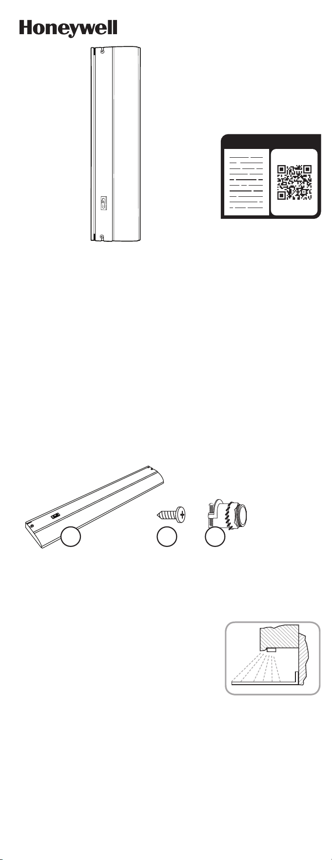
Scan QR code or visit bit.ly/2x6kvSz
44109 (12IN.), 44110 (18IN.), 44112 (24IN.),
44113 (36IN.), 44114 (48IN.)
DIRECT WIRE
LED LIGHT FIXTURE
SAVE THESE INSTRUCTIONS IN A LOCATION CLOSE TO YOUR CABINET
SO YOU CAN REFER TO THEM AT A LATER TIME.
CAUTION: DO NOT USE POWER TOOLS TO SECURE SCREWS, AS
THERE IS A RISK OF STRIPPING THE SCREWS.
DO NOT USE WITH A DIMMING CIRCUIT OR ANY OTHER
ELECTRONICALLY SWITCHED CONTROL.
DO NOT EXCEED THE MAXIMUM CONNECTED UNITS INDICATED ON
THE POWER ADAPTER/LED DRIVER.
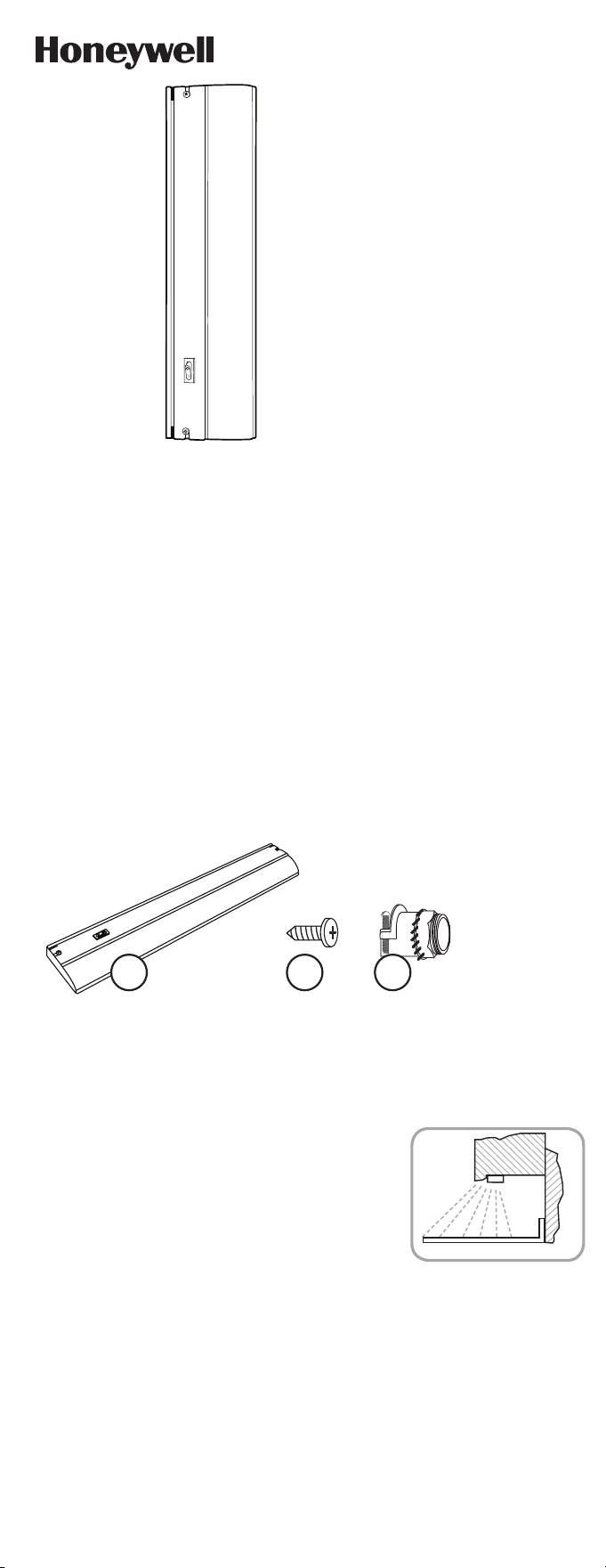
PACKAGE CONTENTS
INSTALLATION PROCEDURE FOR DIRECT
WIRE LIGHT FIXTURE
Note: For kitchen installations, the recommended mounting for
the dimmable LED light fixture is near the front lip of your under
cabinets as shown in the illustration (see Figure 1). The LEDs
will face the front of the cabinet. This provides the best light
distribution across a countertop.
1. Consult a local licensed electrician or electrical
contractor if you are not sure about the installation.
2. Ensure that electricity is TURNED OFF at the main
circuit breaker or fuse box. DO NOT ATTEMPT TO
INSTALL FIXTURE WITH THE POWER ON.
3. Select a suitable dry mounting location (for use
indoors only). Make sure mounting surface is capable
of supporting the LED light fixture.
4. Remove the lens/diffuser by lightly pulling the rear edge
toward the front and upward. The lens/diffuser should
pop out easily.
5. Remove the cover/housing by unscrewing the screws
located on the top of the cover. Firmly push forward on
the bottom front of the housing to unlatch it from the
catch points. The hardware kit is inside the wiring cavity.
FIGURE 1
CABINET
COUNTER TOP
WALL
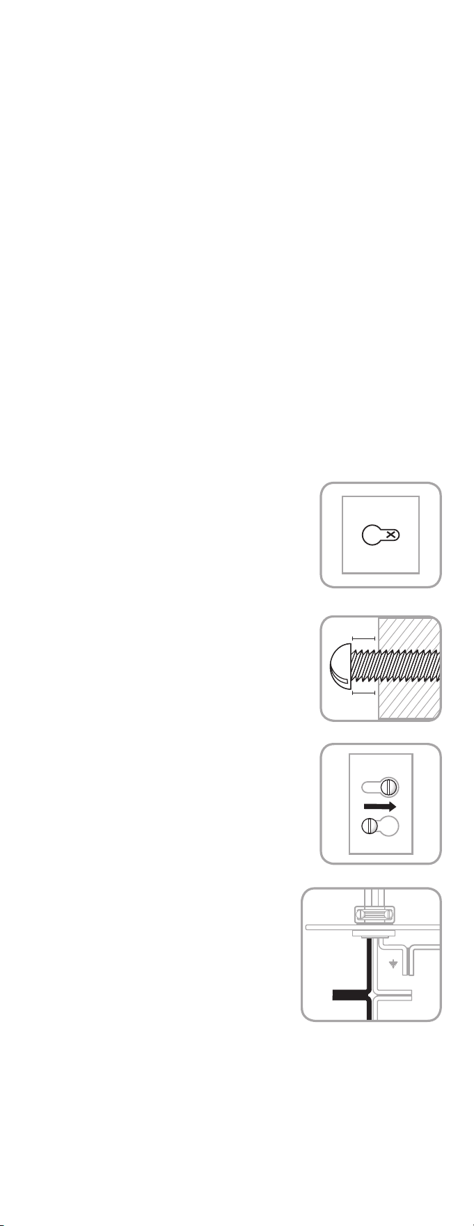
6. Ensure that there is adequate space to install the
fixture by using the base as a mounting template.
While the base is held in place, mark location for pilot
holes (see Figure 2).
7. Choose a suitable knock-out location from those provided
on the fixture. Remove the knock-out with a screwdriver
(not included).
8. Remove the nut and lock washer and insert the threaded
end of the strain relief into the selected opening on the
fixture. Secure the strain relief by tightening the nut and
lock washer. The nut and lock washer should be tightened
with a tool such as a pair of pliers (not included) to ensure
the strain relief is properly grounded to the fixture.
9. It is recommended that a pilot hole be drilled in the
mounting surface for wood screws. Pre-drill holes in
the mounting surface with a 1/16in. (1.5mm) drill bit for
softwoods and a 3/32in. (2.4mm) drill bit for hardwoods.
10. Drive the screws into the mounting surface until
approximately 1/8in. (3.1mm) of space remains under the
head of the screw (see Figure 3).
11. Align the keyholes in the fixture with the two screws and
slide into place (see Figure 4).
12. Tighten screws to secure fixture.
13. For ease of installation, the top cover can be hung on the
base, which is already attached to the cabinet, using the
built-in hanging flanges.
14. Install the armored cable to meet electrical codes. Tighten
the two screws on the strain relief connector to secure
the cable.
15. Connect the hot (black) AC supply wire to the hot (black)
wire of the fixture. Secure the connection with the quick
connects (see Figure 5). Pull wires to check for tightness.
16. Connect the neutral (white) AC supply wire to the neutral
(white) wire of the fixture. Secure the connection with
the wire quick connects (see Figure 5). Pull wires to check
for tightness.
17. Connect the ground (green or bare copper) AC supply wire
to the green or bare copper ground (green or bare copper)
wire of the fixture. Secure the connection with the wire
quick connects (see Figure 5). Pull wires to check for
tightness. If your electrical system contains no grounding
wire, you should consult a qualified electrician before
proceeding with the installation.
18. Ensure that no bare wires are exposed after making the
electrical connections.
19. Arrange the wires inside the fixture and reattach the
cover/housing by reversing the removal instructions.
Ensure all the wires and connections are sealed properly
inside the fixture without “pinching” any wires. Ensure the
top cover screws and washers are secure.
20. Reinsert lens.
21. Turn on the electricity at the circuit breaker or fuse box.
FIGURE 2
FIGURE 3
1/16IN. (1.58MM)
1/8IN.
3.1MM
FIGURE 4
FIGURE 5
INSERT
SLIDE
A B C
A. Light Fixture x1
B. M4 x 12mm short mounting
screw x2
C. Strain relief assembly x1
READ IT OR WATCH IT
Read instructions or watch easy-to-follow video.
Scan QR code or visit bit.ly/2x6kvSz
44109 (12IN.), 44110 (18IN.), 44112 (24IN.),
44113 (36IN.), 44114 (48IN.)
DIRECT WIRE
LED LIGHT FIXTURE
SAVE THESE INSTRUCTIONS IN A LOCATION CLOSE TO YOUR CABINET
SO YOU CAN REFER TO THEM AT A LATER TIME.
CAUTION: DO NOT USE POWER TOOLS TO SECURE SCREWS, AS
THERE IS A RISK OF STRIPPING THE SCREWS.
DO NOT USE WITH A DIMMING CIRCUIT OR ANY OTHER
ELECTRONICALLY SWITCHED CONTROL.
DO NOT EXCEED THE MAXIMUM CONNECTED UNITS INDICATED ON
THE POWER ADAPTER/LED DRIVER.
PACKAGE CONTENTS
INSTALLATION PROCEDURE FOR DIRECT
WIRE LIGHT FIXTURE
Note: For kitchen installations, the recommended mounting for
the dimmable LED light fixture is near the front lip of your under
cabinets as shown in the illustration (see Figure 1). The LEDs
will face the front of the cabinet. This provides the best light
distribution across a countertop.
1. Consult a local licensed electrician or electrical
contractor if you are not sure about the installation.
2. Ensure that electricity is TURNED OFF at the main
circuit breaker or fuse box. DO NOT ATTEMPT TO
INSTALL FIXTURE WITH THE POWER ON.
3. Select a suitable dry mounting location (for use
indoors only). Make sure mounting surface is capable
of supporting the LED light fixture.
4. Remove the lens/diffuser by lightly pulling the rear edge
toward the front and upward. The lens/diffuser should
pop out easily.
5. Remove the cover/housing by unscrewing the screws
located on the top of the cover. Firmly push forward on
the bottom front of the housing to unlatch it from the
catch points. The hardware kit is inside the wiring cavity.
FIGURE 1
CABINET
COUNTER TOP
WALL
6. Ensure that there is adequate space to install the
fixture by using the base as a mounting template.
While the base is held in place, mark location for pilot
holes (see Figure 2).
7. Choose a suitable knock-out location from those provided
on the fixture. Remove the knock-out with a screwdriver
(not included).
8. Remove the nut and lock washer and insert the threaded
end of the strain relief into the selected opening on the
fixture. Secure the strain relief by tightening the nut and
lock washer. The nut and lock washer should be tightened
with a tool such as a pair of pliers (not included) to ensure
the strain relief is properly grounded to the fixture.
9. It is recommended that a pilot hole be drilled in the
mounting surface for wood screws. Pre-drill holes in
the mounting surface with a 1/16in. (1.5mm) drill bit for
softwoods and a 3/32in. (2.4mm) drill bit for hardwoods.
10. Drive the screws into the mounting surface until
approximately 1/8in. (3.1mm) of space remains under the
head of the screw (see Figure 3).
11. Align the keyholes in the fixture with the two screws and
slide into place (see Figure 4).
12. Tighten screws to secure fixture.
13. For ease of installation, the top cover can be hung on the
base, which is already attached to the cabinet, using the
built-in hanging flanges.
14. Install the armored cable to meet electrical codes. Tighten
the two screws on the strain relief connector to secure
the cable.
15. Connect the hot (black) AC supply wire to the hot (black)
wire of the fixture. Secure the connection with the quick
connects (see Figure 5). Pull wires to check for tightness.
16. Connect the neutral (white) AC supply wire to the neutral
(white) wire of the fixture. Secure the connection with
the wire quick connects (see Figure 5). Pull wires to check
for tightness.
17. Connect the ground (green or bare copper) AC supply wire
to the green or bare copper ground (green or bare copper)
wire of the fixture. Secure the connection with the wire
quick connects (see Figure 5). Pull wires to check for
tightness. If your electrical system contains no grounding
wire, you should consult a qualified electrician before
proceeding with the installation.
18. Ensure that no bare wires are exposed after making the
electrical connections.
19. Arrange the wires inside the fixture and reattach the
cover/housing by reversing the removal instructions.
Ensure all the wires and connections are sealed properly
inside the fixture without “pinching” any wires. Ensure the
top cover screws and washers are secure.
20. Reinsert lens.
21. Turn on the electricity at the circuit breaker or fuse box.
FIGURE 2
FIGURE 3
1/16IN. (1.58MM)
1/8IN.
3.1MM
FIGURE 4
FIGURE 5
INSERT
SLIDE
A B C
A. Light Fixture x1
B. M4 x 12mm short mounting
screw x2
C. Strain relief assembly x1
Suppliers Declaration of Conformity | Model #: 44109, 44110, 44112, 44113, 44114 | Jasco
Products Co., 10 E. Memorial Rd., Oklahoma City, OK 73114, www.byjasco.com
This device complies with Part 15 of the FCC and Industry Canada license-exempt RSS
standards. Operation is subject to the following two conditions: (1) this device may not cause
harmful interference, and (2) this device must accept any interference received, including
interference that may cause undesired operation.
FCC NOTE: The manufacturer is not responsible for any radio or TV interference caused by
unauthorized modifications to this equipment. Such modifications could void the user’s
authority to operate the equipment.
NOTE: This equipment has been tested and found to comply with the limits for a Class B
digital device, pursuant to Part 15 of the FCC Rules. These limits are designed to provide
reasonable protection against harmful interference in a residential installation. This
equipment generates, uses and can radiate radio frequency energy, and if not installed
and used in accordance with the instructions, may cause harmful interference to radio
communications. However, there is no guarantee interference will not occur in a particular
installation. If this equipment does cause harmful interference to radio or television
reception, which can be determined by turning the equipment off and on, the user is
encouraged to try to correct the interference by one or more of the following measures:
— Reorient or relocate the receiving antenna.
— Increase the separation between the equipment and receiver.
— Connect the equipment into an outlet on a circuit different from which the receiver
is connected.
— Consult the dealer or an experienced radio/TV technician for help.
CAN ICES-3(B)/NMB-3(B)
Questions? Contact our U.S.-based Consumer Care at 1-855-698-8324,
Monday–Friday, 7AM–8PM CST.
For the most up-to-date product support, accessories, electronic (PDF) format manuals and
more, visit www.byjasco.com/support.
DO NOT RETURN THIS
PRODUCT TO THE STORE
STOP
FCC/IC - EN
SPECIFICATIONS
The Honeywell Trademark is used under license from Honeywell International Inc.
Honeywell International Inc. makes no representation or warranties with respect to this product.
This product is manufactured by Jasco Products Company LLC.
This Jasco product comes with a 2-year limited warranty. Visit www.byjasco.com for warranty details.
MADE IN CHINA/HECHO EN CHINA
©JASCO 2019 | 44109, 44110, 44112, 44113, 44114 | 06/19/19 v1
Jasco Products Company LLC.
10 E. Memorial Road
Oklahoma City, OK 73114
120VAC 60Hz
3.4W
270 Lumens
82 CRI
2700K White
120VAC 60Hz
5W
414 Lumens
82 CRI
2700K White
44109 (12IN.) 44110 (18IN.)
RISK OF ELECTRICAL SHOCK
• DO NOT USE IN WET LOCATIONS
• USE INDOORS ONLY
• USE ONLY INSULATED STAPLES OR
PLASTIC TIES TO SECURE THE CORDS
• ROUTE AND SECURE THE CORDS SO
THAT THEY WILL NOT BE PINCHED OR
DAMAGED
NO SERVICEABLE PARTS
NON-REPLACEABLE LEDS
LED LIGHT OUTPUT IS STRONG
ENOUGH TO INJURE HUMAN EYES.
PRECAUTIONS MUST BE TAKEN TO
PREVENT LOOKING DIRECTLY AT THE
LEDS WITH UNAIDED EYES FOR MORE
THAN A FEW SECONDS.
RISK OF FIRE
• NOT INTENDED FOR ILLUMINATION OF
AQUARIUMS
NOT INTENDED FOR USE ABOVE
STOVES, COOK TOPS, SINKS OR OTHER
HEAT PRODUCING APPLIANCES, SUCH
AS COFFEE MAKERS, TOASTERS, OR
TOASTER OVENS
• NOT INTENDED FOR RECESSED
INSTALLATION IN CEILINGS OR
SOFFITS
• NOT INTENDED FOR SURFACE
INSTALLATION INSIDE OR ON TOP
OF BUILT-IN FURNISHINGS SUCH AS
KITCHEN CABINETS, CHINA CABINETS,
OR TROPHY CASES
• DO NOT CONCEAL POWER SUPPLY
CORD OR LINKING CORDS INSIDE
A WALL, CEILING, SOFFIT, KITCHEN
CABINET, OR SIMILAR PERMANENT
STRUCTURE
• DO NOT RUN THE POWER SUPPLY
CORD OR LINKING CORDS THROUGH
HOLES IN WALLS, CEILINGS OR
FLOORS
WARNING
120VAC 60Hz
6.5W
530 Lumens
82 CRI
2700K White
44112 (24IN.)
120VAC 60Hz
9.3W
790 Lumens
82 CRI
2700K White
120VAC 60Hz
13.8W
1142 Lumens
82 CRI
2700K White
44113 (36IN.) 44114 (48IN.
44109 (12IN.), 44110 (18IN.), 44112 (24IN.),
44113 (36IN.), 44114 (48IN.)
CONEXIÓN DIRECTA
ACCESORIO DE LUZ LED
GUARDE ESTAS INSTRUCCIONES EN UN LUGAR CERCANO A SU
GABINETE PARA QUE PUEDA CONSULTARLAS MÁS ADELANTE.
PRECAUCIÓN: NO USE HERRAMIENTAS ELÉCTRICAS PARA FIJAR LOS
TORNILLOS, YA QUE EXISTE EL RIESGO DE BARRERLOS.
NO UTILIZAR CON UN CIRCUITO DE ATENUACIÓN U OTRO CONTROL
ELECTRÓNICO.
NO EXCEDA EL MÁXIMO DE UNIDADES CONECTADAS QUE SE INDICA
EN EL ADAPTADOR DE POTENCIA/CONTROLADOR DE LED.
CONTENIDO DEL PAQUETE
PROCEDIMIENTO DE INSTALACIÓN DEL
ACCESORIO DE LUZ CON CONEXIÓN DIRECTA
Nota: Para instalaciones en cocinas, se recomienda que el
aparato de luz LED atenuable se instale cerca del borde frontal
de los gabinetes como se muestra en la ilustración (ver Figura
1). La luz LED debe mirar hacia el frente del gabinete. De esta
manera, logrará la mejor distribución de luz en toda la encimera.
1. Consulte con un electricista profesional o un contratista
especializado en electricidad si no está seguro de cómo
instalar este aparato.
2. Asegúrese de que la electricidad ESTÉ DESCONECTADA
en el disyuntor o panel de fusiles principal. NO INTENTE
INSTALAR ESTE APARATO CON EL SUMINISTRO
ELÉCTRICO CONECTADO.
3. Seleccione un lugar seco adecuado para la instalación
(solo para uso en interiores). Asegúrese de que la superficie
en la que desea instalar el aparato de iluminación LED
podrá soportar el peso.
4. Quite el lente/difusor jalando suavemente el borde
posterior hacia adelante y arriba. El lente/difusor debería
desengancharse fácilmente.
5. Quite la cubierta/carcasa desatornillando los tornillos
ubicados en la parte superior de esta. Para desengancharla
de los puntos de sujeción, empuje con firmeza sobre la
parte inferior frontal de la carcasa. El kit de ferretería está
dentro de la cavidad del cableado.
FIGURA 1
GABINETE
ENCIMERA
PARED
6. Asegúrese de que haya suficiente lugar para instalar el
aparato utilizando la base como plantilla de instalación.
Mientras sostiene la base, marque el lugar donde hará los
orificios (ver Figura 2).
7. Escoja un lugar marcado en el aparato. Quite la parte
marcada con un destornillador (no incluido).
8. Quite la tuerca y la arandela de sujeción e inserte el
extremo roscado del sujetacable protector en la apertura
seleccionada del aparato. Fije el sujetacable ajustando la
tuerca y la arandela. La tuerca y la arandela se deben sujetar
con una herramienta como una pinza (no incluida) a fin de
garantizar que el sujetacable protector esté debidamente
conectado al aparato.
9. Se recomienda perforar un orificio guía en la superficie de
instalación en la que se colocarán los tornillos para madera.
Previamente, perfore orificios en la superficie de montaje con
una broca de 1/16 pulgadas (1,5 mm) para madera blanda y
una broca de 3/32 pulgadas (2,4 mm) para madera dura.
10. Coloque los tornillos en la superficie de montaje hasta que
quede un espacio aproximado de 1/8 pulgada (3,1 mm) entre
la superficie y la cabeza del tornillo (ver Figura 3).
11. Alinee los orificios en el aparato con los dos tornillos y
colóquelo en su lugar (ver Figura 4).
12. Ajuste los tornillos para fijar el aparato.
13. Para facilitar la instalación, la cubierta superior se puede
colgar de la base, que ya está sujetada al gabinete, utilizando
las bridas colgantes incorporadas.
14. Instale el cable reforzado para cumplir con los códigos
eléctricos. Ajuste los dos tornillos en el sujetacable para que
queden sujetos.
15. Conecte el cable vivo (negro) de alimentación de CA
al cable vivo (negro) del aparato. Fije la conexión con los
conectores a presión (ver Figura 5). Jale los cables para
verificar que estén ajustados.
16. Conecte el cable neutral (blanco) de alimentación de CA
al cable neutral (blanco) del aparato. Fije la conexión con
los conectores a presión (ver Figura 5). Jale los cables para
verificar que estén ajustados.
17. Conecte el cable a tierra (verde o cobre) de alimentación de
CA al cable a tierra (verde o cobre) del aparato. Fije la conexión
con los conectores a presión (ver Figura 5). Jale los cables
para verificar que estén ajustados. Si su sistema eléctrico no
tiene un cable de puesta a tierra, consulte a un electricista
profesional antes de instalar el aparato.
18. Asegúrese de que no quede expuesto ningún cable pelado
después de hacer las conexiones eléctricas.
19. Ordene los cables dentro del aparato y vuelva a colocar la
cubierta/carcasa siguiendo en orden inverso las instrucciones
para quitar la carcasa. Asegúrese de que todos los cables y las
conexiones estén debidamente sellados dentro del aparato sin
que haya quedado apretado ningún cable. Asegúrese de que
los tornillos y arandelas de la cubierta estén bien sujetados.
20. Vuelva a colocar el lente.
21. Restablezca la electricidad en el disyuntor o panel de
fusiles.
FIGURA 2
FIGURA 3
1/16IN. (1.58MM)
1/8IN.
3.1MM
FIGURA 4
FIGURA 5
INSERTE
DESLICE
A. Luminaria x1
B. Tornillos cortos de montaje
M4 x 12 mm x2
C. Conjunto de sujetacable
protector x1
A B C
¿Preguntas? Comuníquese con nuestro Centro de atención al cliente con sede en EE. UU. al
1-855-698-8324, de lunes a viernes, de 7:00 a. m. a 8:00 p. m. CST (hora central estándar).
Para recibir el soporte técnico más actualizado sobre productos, accesorios, manuales en
formato digital (PDF), entre otros, visite www.byjasco.com/support
NO DEVUELVA ESTE
PRODUCTO A LA TIENDA
¡PARE!
Declaración de conformidad del proveedor | Modelo #: 44109, 44110, 44112, 44113,
44114 | Jasco Products Co., 10 E. Memorial Rd., Oklahoma City, OK 73114, www.byjasco.com
Este dispositivo cumple con las especificaciones del apartado 15 de las normas de la FCC
y con las especificaciones de las normas radioeléctricas (RSS) del Ministerio de Industria
de Canadá aplicables a aparatos exentos de licencia. El funcionamiento está sujeto a las
siguientes dos condiciones: (1) este dispositivo no debe provocar interferencia perjudicial, y
(2) este dispositivo debe aceptar toda interferencia que reciba, incluso la que pudiera causar
un funcionamiento no deseado.
NOTA DE LA FCC: El fabricante no se hace responsable de ninguna interferencia de radio
o TV ocasionada por modificaciones. no autorizadas efectuadas a este dispositivo. Dichas
modificaciones podrían anular la autoridad del usuario para utilizar este dispositivo.
NOTA: Este equipo ha sido probado y cumple con los límites para aparatos digitales de Clase
B
,de conformidad con el apartado 15 de la normativa de la FCC. Estos límites están diseñados
para proveer protección razonable contra interferencias perjudiciales en instalaciones
residenciales. Este dispositivo genera, usa y puede irradiar energía de radiofrecuencias y,
si no se instala y usa según las instrucciones, puede provocar interferencia perjudicial a
las radiocomunicaciones. No obstante, no hay garantías de que no ocurrirá interferencia
en una instalación en particular. Si este equipo genera alguna interferencia perjudicial a la
recepción de radio o televisión, lo que puede determinarse encendiendo y apagando el equipo,
se recomienda que el usuario intente corregir la interferencia aplicando una o más de las
siguientes medidas:
— Reoriente o reubique la antena receptora.
— Incrementar la separación entre el equipo y el receptor.
— Conectar el dispositivo a un tomacorriente de un circuito diferente del circuito al que el
receptor está conectado.
— Consulte al distribuidor o a un técnico con experiencia en radio/televisión para solicitar
asistencia.
CAN ICES-3(B)/NMB-3(B)
FCC/IC
ESPECIFICACIONES
RIESGO DE DESCARGA ELÉCTRICA
• NO UTILICE EN LUGARES HÚMEDOS
• SOLO PARA USO EN INTERIORES
• PARA FIJAR LOS CABLES, SOLO USE
GRAPAS AISLADAS O PRECINTOS DE
PLÁSTICO.
• PASE Y FIJE LOS CABLES DE MODO
QUE NO QUEDEN APRETADOS NI SE
DAÑEN
NO TIENE PIEZAS QUE EL USUARIO
PUEDA REPARAR.
LED NO REEMPLAZABLES
LA LUMINOSIDAD DE LAS LED ES
MUY ALTA. PUEDE DAÑAR LOS OJOS.
TOME PRECAUCIONES PARA NO
IRAR DIRECTAMENTE A LAS LUCES
LED CON LOS OJOS DESCUBIERTOS
POR MÁS DE UNOS SEGUNDOS.
RIESGO DE INCENDIO
• ESTA UNIDAD NO ESTÁ DISEÑADA PARA
LA ILUMINACIÓN DE PECERAS
• NO SE DEBE USAR SOBRE HORNILLOS,
PLACAS DE COCINA, FREGADEROS
NI NINGÚN OTRO DISPOSITIVO QUE
GENERE CALOR, COMO CAFETERAS,
TOSTADORAS NI HORNOS ELÉCTRICOS
• ESTA UNIDAD NO ESTÁ DISEÑADA PARA
MONTAJE EMPOTRADO AL TECHO O
EN UN SOFITO
• ESTA UNIDAD NO ESTÁ DISEÑADA
PARA INSTALARSE EN EL INTERIOR NI
ENCIMA DE MUEBLES EMPOTRADOS,
COMO MUEBLES DE COCINA O
VITRINAS
• NO OCULTE EL CABLE DE
ALIMENTACIÓN ELÉCTRICA O LOS
CABLES DE CONEXIÓN DENTRO
DE UNA PARED, EL CIELO RASO, UN
SOFITO, UN MUEBLE DE COCINA O
UNA ESTRUCTURA SIMILAR QUE SEA
PERMANENTE
• NO PASE EL CABLE DE ALIMENTACIÓN
ELÉCTRICA NI LOS CABLES DE
CONEXIÓN POR ORIFICIOS EN
PAREDES, EL CIELO RASO O EL SUELO
ADVERTENCIA
120VAC 60Hz
3.4W
270 Lúmenes
82 CRI
Blanca 2700K
120VAC 60Hz
5W
414 Lúmenes
82 CRI
Blanca 2700K
44109 (12in.) 44110 (18in.)
120VAC 60Hz
6.5W
530 Lúmenes
82 CRI
Blanca 2700K
44112 (24in.)
120VAC 60Hz
9.3W
790 Lúmenes
82 CRI
Blanca 2700K
120VAC 60Hz
13.8W
1142 Lúmenes
82 CRI
Blanca 2700K
44113 (36in.) 44114 (48in.)