READ IT OR WATCH IT
Read instructions or watch easy-to-follow video.
Scan QR code or visit http://bit.ly/2N9QQ5I
44415 (6 PACK), 44416 (5 PACK), 44417 (4 PACK),
44418 (3 PACK), 44419 (2 PACK)
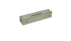
PLUG-IN BRIGHT STRIPS
LED LIGHT FIXTURE
CAUTION: DO NOT USE POWER TOOLS TO SECURE SCREWS, AS
THERE IS A RISK OF STRIPPING THE MOUNTING HOLES.
DO NOT USE WITH A DIMMER OR DIMMING CIRCUIT.
DO NOT EXCEED THE MAXIMUM CONNECTED UNITS INDICATED ON
THE POWER ADAPTER/LED DRIVER.
SAVE THESE INSTRUCTIONS FOR POSSIBLE FUTURE USE.
IMPORTANT SAFETY INSTRUCTIONS
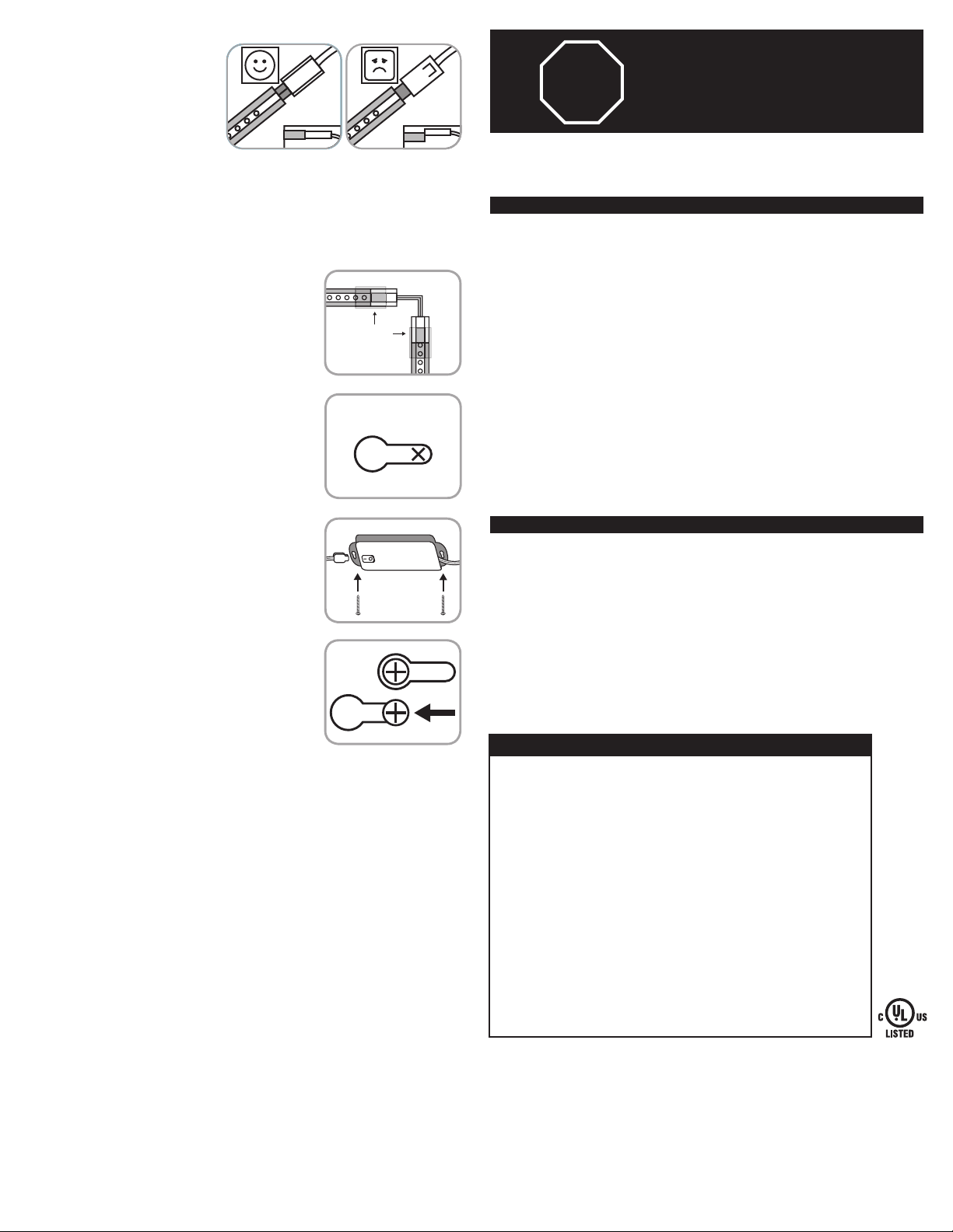
The Bright Strips have a polarized plug (one blade is wider than the other) to reduce the risk of
electric shock. This plug fits in a polarized outlet only one way. If the plug does not fit fully in the
outlet, reverse the plug. If it still does not fit, contact a qualified electrician. Do not alter the plug.
Read entire installation instructions before beginning installation.
INSTALLATION PROCEDURE FOR PLUGIN BRIGHT STRIPS
1. DO NOT ATTEMPT TO INSTALL BRIGHT STRIPS WHILE PLUGGED IN.
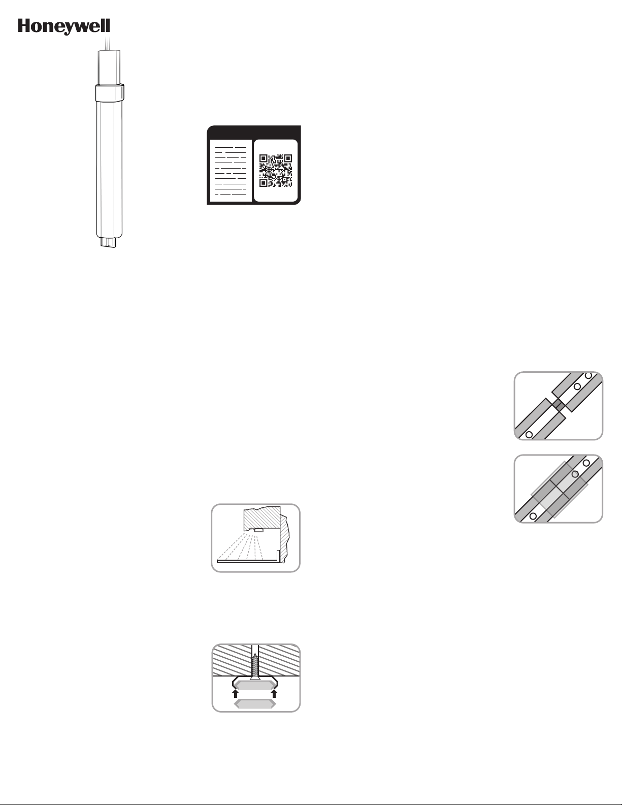
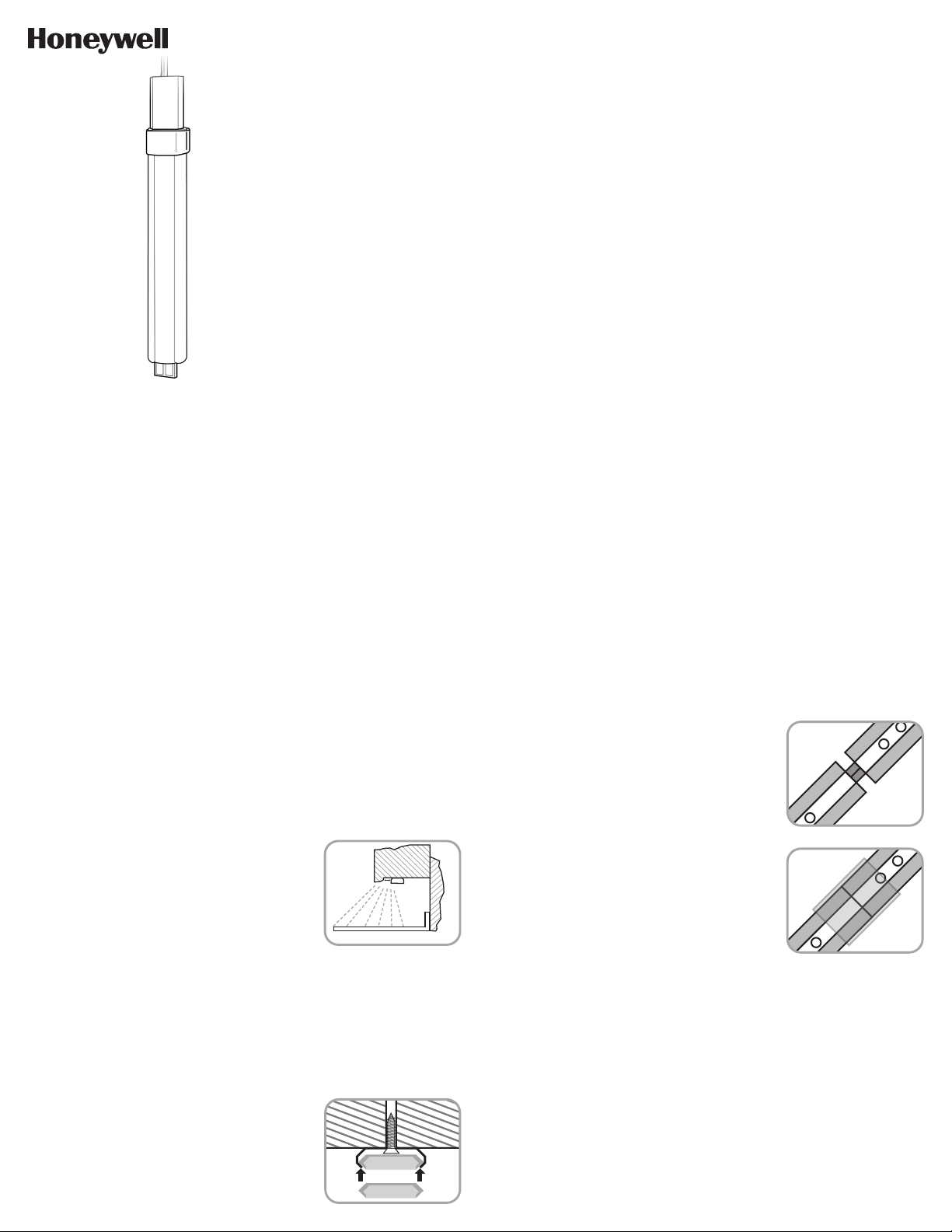
2. Carefully plan the installation prior to mounting the Bright Strips. Make sure the 5ft. power
supply cord will reach the nearest electrical outlet and the 18in. linking cord will reach the
first Bright Strip. For kitchen installations, the recommended mounting for the Bright Strips is
under the cabinets 1in. from the front lip (see Figure 1).
This provides the best light distribution across a countertop.
3. Select a suitable dry mounting location (for indoor use only).
Make sure the mounting surface can support the fixture and
LED Driver.
4. The Bright Strips can be mounted in two configurations:
a. Multiple Bright Strips end-to-end.
b. Multiple Bright Strips connected with an 18in. linking cord.
5. Before drilling any holes, locate position where Bright Strips
and LED Driver will be mounted.
6. Make sure there is enough room for each Bright Strip
and linking connector based on the chosen mounting
configuration.
7. There are two metal mounting clips and two plastic securing clips provided with each Bright
Strip, however, all of these will not be required based on the mounting configuration.
8. One Bright Strip has a clear, plastic end cap. This will be the very last Bright Strip connected in
either configuration.
1. Two metal mounting clips are suggested for each Bright
Strip, which will be positioned 2in. from each end of the
strip.
2. Begin installation with the first Bright Strip in the chain
which will be closest to the LED Driver.
3. Hold the Bright Strip in the desired location and make two
marks on the mounting surface at the center of the strip,
approximately 2in. from each end of the strip.
4. To ensure ease of mounting, pre-drill both holes in the
mounting surface with a 1/16in. (1.5mm) drill bit at the
marked mounting hole locations..
5. Place the provided 1/2in. wood screws in the metal
mounting clips and drive the screws into the pre-drilled
holes in the mounting surface. Use only a #1 Philips head
screwdriver when screwing in brackets to avoid stripping
the mounting holes (do not use power tools)(see Figure 2).
6. The Bright Strip with the clear plastic end cap is to be
connected last.
7. Snap the Bright Strip into the mounting clips and ensure
it is firmly held in place (see Figure 2). Make sure the male
connection point is facing the direction of where the LED
Driver will be mounted.
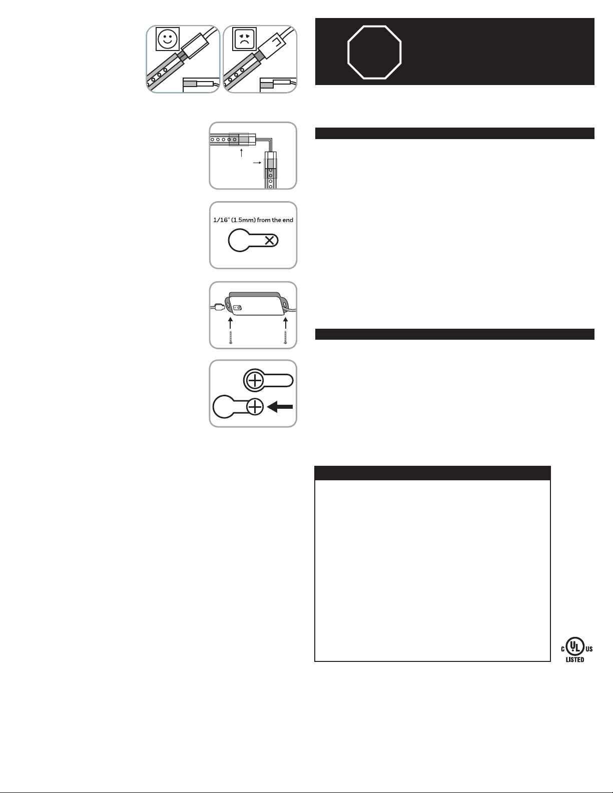
8. Connect a linking cord by placing the exposed male
connector of the linking cord into the matching female
connection point on the installed Bright Strip (see Figure 5).
1. Only one metal mounting clip is needed for each Bright
Strip, which will be positioned in the center of each strip.
2. To ensure ease of mounting, the mounting clips for each
Bright Strip MUST be positioned in a straight line. This is
even more important as more strips are connected end-
to-end.
3. Hold the first Bright Strip in the desired location and make
one mark on the mounting surface at the center of the
Bright Strip’s location. Make sure the linking cord from the
LED Driver will easily reach the strip.
4. Using a straight edge from the mark above, draw a straight line for each additional Bright
Strip that will be connected. Each Bright Strip is 10in. long.
5. Mark the location for each additional mounting clip along the straight line 10in. apart,
starting from the mark for the first Bright Strip above.
6. To ensure ease of mounting, pre-drill holes in the mounting surface with a 1/16in. (1.5mm)
drill bit at the marked mounting hole locations.
7. Place the provided 1/2in. wood screws in the metal
mounting clips and drive the screws into the pre-drilled
holes in the mounting surface. Use only a #1 Philips head
screwdriver when screwing in brackets to avoid stripping
the mounting holes (do not use power tools). Repeat for all
mounting clips (see Figure 2).
8. Connect Bright Strips together by placing the exposed
male connector of one Bright Strip into the matching
female connection point of another Bright Strip.
a. The Bright Strip with the clear plastic end cap is to be
connected last.
b. Take care that the lens and LEDs are facing the same
direction on all Bright Strips, and that they match up
flush with each other (see Figure 3).
9. Snap the provided clear securing clip over the connection
point over the lens to firmly join the strips together (see
Figure 4).
10. Repeat for all additional end-to-end connected Bright
Strips. Connect the Bright Strip with the clear plastic end
cap last.
11. Snap the connected chain of Bright Strips into the
mounting clips and ensure that it is firmly held in place. Make sure the remaining male
connection point is facing the direction of where the LED Driver will be mounted.
MOUNTING ENDTOEND (NO LINKING CORD):
MOUNTING BRIGHT STRIPS USING THE 18” LINKING CORD
FIGURE 1
CABINET
1in.
COUNTER TOP
WALL
FIGURE 2
FIXTURE
FIXTURE
FIGURE 3
FIGURE 4
The Honeywell trademark is used under license from Honeywell International Inc.
Honeywell International Inc. makes no representation or warranties with respect to this product.
This product is manufactured by Jasco Products Company LLC.
This Jasco product comes with a limited-lifetime warranty. Visit www.byjasco.com for warranty details.
MADE IN CHINA/HECHO EN CHINA
©JASCO 2019 | 44415, 44416, 44417, 44418, 44419 | 11/13/19 v2
Jasco Products Company LLC.
10 E. Memorial Road
Oklahoma City, OK 73114
RISK OF ELECTRICAL SHOCK
• DO NOT USE IN WET LOCATIONS
• USE INDOORS ONLY
• USE ONLY INSULATED STAPLES OR
PLASTIC TIES TO SECURE THE CORDS
• ROUTE AND SECURE THE CORDS SO
THAT THEY WILL NOT BE PINCHED OR
DAMAGED
NO SERVICEABLE PARTS
NONREPLACEABLE LEDS
LED LIGHT OUTPUT IS STRONG
ENOUGH TO INJURE HUMAN EYES.
PRECAUTIONS MUST BE TAKEN TO
PREVENT LOOKING DIRECTLY AT THE
LEDS WITH UNAIDED EYES FOR MORE
THAN A FEW SECONDS.
RISK OF FIRE
• NOT INTENDED FOR ILLUMINATION OF
AQUARIUMS
• NOT INTENDED FOR USE ABOVE
STOVES, COOK TOPS, SINKS OR OTHER
HEAT PRODUCING APPLIANCES, SUCH
AS COFFEE MAKERS, TOASTERS, OR
TOASTER OVENS
• NOT INTENDED FOR RECESSED
INSTALLATION IN CEILINGS OR
SOFFITS
• NOT INTENDED FOR SURFACE
INSTALLATION INSIDE OR ON TOP
OF BUILTIN FURNISHINGS SUCH AS
KITCHEN CABINETS, CHINA CABINETS,
OR TROPHY CASES
• DO NOT CONCEAL POWER SUPPLY
CORD OR LINKING CORDS INSIDE
A WALL, CEILING, SOFFIT, KITCHEN
CABINET, OR SIMILAR PERMANENT
STRUCTURE
• DO NOT RUN THE POWER SUPPLY
CORD OR LINKING CORDS THROUGH
HOLES IN WALLS, CEILINGS OR
FLOORS
WARNING
9. Connect the next Bright Strip in the
chain to the linking cord by placing
the exposed male connector of the
next Bright Strip into the matching
female connection point of the
installed linking cord.
10. Snap a provided clear securing clip
over both connection points of the
linking cord to the Bright Strips
(see Figure 6).
11. Repeat steps 3.11. until all Bright Strips in the chain are mounted.
1. The Bright Strips come with an in-line LED Driver with a
built in ON/OFF switch.
2. To mount the LED Driver, place the LED Driver in desired
location and clearly mark the locations for the mounting
holes (see Figure 7).
3. Pre-drill holes in the mounting surface with a 1/16in.
(1.5mm) drill bit for soft woods and a 3/32in. (2.4mm) drill
bit for hardwoods. Drive the 5/8in. wood screws provided
in the mounting hardware into the mounting surface until
approximately 1/16in. (1.5mm) of space remains under the
head of the screw (see Figure 8).
4. Place LED Driver onto the screws and slide to secure in
place (see Figure 9). If necessary, tighten screws to secure
in place.
5. Connect the LED Driver to the Bright Strips by placing the
female connector of the linking cord coming from the LED
Driver onto the male connection point of the first Bright
Strip in the chain, ensuring the connector is flush with the
fixture. Snap the clear securing tab over the connection
point (see Figure 5 & 6).
6. Plug the 3-pin connector of the power supply cord into the
corresponding connection point on the LED Driver (see
Figure 8).
7. Plug the power supply cord plug into any 120V/60Hz outlet.
8. The connected Bright Strips turn ON/OFF with the ON/OFF
switch on the LED Driver.
MOUNTING THE LED DRIVER
AND OPERATION OF BRIGHT STRIPS
This device complies with Part 15 of the FCC and Industry Canada license-exempt RSS
standards. Operation is subject to the following two conditions: (1) this device may not cause
harmful interference, and (2) this device must accept any interference received, including
interference that may cause undesired operation.
FCC NOTE: The manufacturer is not responsible for any radio or TV interference caused by
unauthorized modifications to this equipment. Such modifications could void the user’s
authority to operate the equipment.
NOTE: This equipment has been tested and found to comply with the limits for a Class B
digital device, pursuant to Part 15 of the FCC Rules. These limits are designed to provide
reasonable protection against harmful interference in a residential installation. This
equipment generates, uses and can radiate radio frequency energy, and if not installed
and used in accordance with the instructions, may cause harmful interference to radio
communications. However, there is no guarantee interference will not occur in a particular
installation. If this equipment does cause harmful interference to radio or television
reception, which can be determined by turning the equipment off and on, the user is
encouraged to try to correct the interference by one or more of the following measures:
— Reorient or relocate the receiving antenna.
— Increase the separation between the equipment and receiver.
— Connect the equipment into an outlet on a circuit different from which the receiver
is connected.
— Consult the dealer or an experienced radio/TV technician for help.
CAN ICES3(B)/NMB3(B)
Questions? Contact our U.S.-based Consumer Care at 18556988324,
MondayFriday, 7AM8PM CST.
For the most up-to-date product support, accessories, electronic (PDF) format manuals and
more, visit www.byjasco.com/support.
DO NOT RETURN THIS
PRODUCT TO THE STORE
STOP
FCC/IC - EN
SPECIFICATIONS
120VAC 60Hz
20.5W
2040 Lumens
82 CRI
2700K CCT White
120VAC 60Hz
14.5W
1360 Lumens
82 CRI
2700K CCT White
120VAC 60Hz
8W
680 Lumens
82 CRI
2700K CCT White
120VAC 60Hz
17.5W
1700 Lumens
82 CRI
2700K CCT White
120VAC 60Hz
11.5W
1020 Lumens
82 CRI
2700K CCT White
44415 (6 PACK) 44417 (4 PACK)
44419 (2 PACK)
44416 (5 PACK)
44418 (3 PACK)
FIGURE 5
FIGURE 7
FIGURE 8
FIGURE 9
FIGURE 6
Securing
Clip
18”
Linking
Cord
44415 (PACK DE 6 UNIDADES), 44416 (PACK DE 5
UNIDADES), 44417 (PACK DE 4 UNIDADES), 44418
(PACK DE 3 UNIDADES), 44419 (PACK DE 2 UNIDADES)
ACCESORIO DE LUZ LED
CON BANDAS BRILLANTES ENCHUFABLES
PRECAUCIÓN: NO USAR HERRAMIENTAS ELÉCTRICAS PARA AJUSTAR
LOS TORNILLOS, PODRÍAN DAÑAR LOS ORIFICIOS DE MONTAJE.
NO USAR CON REGULADOR DE INTENSIDAD NI CON CIRCUITOS
REGULADORES DE INTENSIDAD.
NO CONECTAR MÁS UNIDADES DE LAS INDICADAS EN EL
ADAPTADOR ELÉCTRICO/CONTROLADOR LED.
GUARDAR ESTAS INSTRUCCIONES PARA REFERENCIA FUTURA.
INSTRUCCIONES IMPORTANTES DE SEGURIDAD
Las tiras luminosas tienen un enchufe polarizado (una patilla es más ancha que la otra) para
reducir el riesgo de descarga eléctrica. El enchufe solo podrá conectarse en un tomacorriente
polarizado en una sola posición. Si no puede colocarlo por completo en el tomacorriente, gire
el enchufe. Si aun así no puede colocarlo, llame a un electricista habilitado. No modifique el
enchufe. Lea todas las instrucciones antes de comenzar la instalación.
PROCESO DE INSTALACIÓN PARA
LAS TIRAS LUMINOSAS CONECTABLES
1. NO INTENTE INSTALAR LAS BANDAS BRILLANTES SI ESTÁN ENCHUFADAS.
2. Antes de colocar las tiras luminosas, planifique detenidamente la instalación. Asegúrese
de que la longitud del cable de alimentación de 1,5 m (5 pies) será suficiente para alcanzar
la toma eléctrica más cercana, y de que el cable de conexión de 45 cm (18») llegue hasta
la primera tira luminosa. En el caso de que las tiras luminosas se instalen en la cocina, se
recomienda que se coloquen debajo de los armarios a 2,5 cm (1») del borde delantero (ver
Imagen 1). De esta forma, logrará la mejor distribución de
luz sobre la mesa para cocinar.
3. Seleccione un lugar seco para instalar las tiras (solo sirven
para interiores). Asegúrese de que la superficie que elija
para colocarlas soporte el aplique y el controlador LED.
4. Las tiras luminosas pueden instalarse de dos modos:
a. Varias tiras luminosas de extremo a extremo.
b. Varias tiras luminosas conectadas con un cable de
conexión de 45 cm (18»).
5. Antes de hacer los orificios, ubique las tiras luminosas
y el controlador LED en las posiciones en las que
desea instalarlos.
6. Asegúrese de haya espacio suficiente para cada tira luminosa y los conectores, teniendo en
cuenta el modo de instalación que haya elegido.
7. Con cada tira luminosa, se proveen dos sujetadores metálicos para el montaje y dos
sujetadores plásticos
para fijarlas; sin embargo, es posible que no tenga que usar todos estos accesorios según el
modo de instalación que elija.
8. Una de las tiras luminosas contiene una tapa plástica y transparente del extremo; esta será la
última tira que tendrá que conectar, independientemente del modo de instalación que elija..
1. Se recomienda utilizar dos sujetadores metálicos para el montaje por cada tira luminosa;
estos deberán colocarse a 5,08 cm (2») de cada extremo de la tira.
2. Comience la instalación con la primera tira luminosa de la cadena que quedará más cerca del
controlador LED.
3. Sostenga la primera tira luminosa en la ubicación deseada y haga dos marcas sobre la
superficie de montaje desde el centro de la tira, aproximadamente, a 5,08 cm de cada uno de
sus extremos.
4. Para facilitar la instalación, perfore previamente los dos orificios en la superficie de montaje
con una broca de 1,5 mm (1/16») en las ubicaciones marcadas.
5. Coloque los tornillos para madera de 1,27 cm (1/2») provistos en los sujetadores metálicos
para el montaje y atorníllelos en los orificios perforados previamente en la superficie de
montaje. Cuando atornille los soportes, utilice únicamente un destornillador Philips n.º 1, a
fin de evitar dañar los orificios de montaje (no utilice herramientas eléctricas). (Ver Imagen 2).
6. La tira luminosa que contiene una tapa plástica y transparente del extremo deberá
conectarse última
1. Solo necesita usar un sujetador metálico para el montaje
por cada tira luminosa; tendrá que colocarlo en el centro
de cada tira.
2. Para que la instalación sea fácil, DEBERÁ colocar los
sujetadores para el montaje en cada tira luminosa
siguiendo una línea recta. Esto adquiere aún más
importancia a medida que conecta más tiras
de extremo a extremo.
3. Sostenga la primera tira luminosa en la ubicación deseada
y haga una marca sobre la superficie de montaje justo
donde se ubique el centro de la tira luminosa. Asegúrese
de que el cable de conexión del controlador LED llegue sin
dificultad a la tira.
4. Guiándose con una regla desde la marca que hizo, dibuje una línea recta para cada tira
luminosa adicional que vaya a conectar. Cada tira luminosa mide 25,4 cm (10») de largo.
5. Sobre la línea recta, marque la ubicación de cada sujetador adicional a una distancia de 25,4
cm (10»), a partir de la marca de la primera tira luminosa que se describe arriba.
6. Para facilitar la instalación, perfore previamente los orificios en la superficie de
montaje con una broca de 1,5 mm (1/16»)
en las ubicaciones marcadas.
7. Coloque los tornillos para madera de 1,27 cm (1/2»)
provistos en los sujetadores metálicos para el montaje
y atorníllelos en los orificios perforados previamente en
la superficie de montaje. Cuando atornille los soportes,
utilice únicamente un destornillador Philips n.º 1, a
fin de evitar dañar los orificios de montaje (no utilice
herramientas eléctricas). Repita el procedimiento en todos
los sujetadores para el montaje (ver Imagen 2).
8. Conecte las tiras luminosas insertando el conector macho
expuesto de una tira luminosa en la conexión hembra
compatible de otra tira luminosa.
a. La tira luminosa que contiene una tapa plástica y
transparente del extremo deberá conectarse última.
b. Verifique que los cristales y las luces LED de todas las
tiras luminosas apunten hacia la misma dirección, y que
estén alineadas entre sí (ver Imagen 3).
9. Coloque a presión el sujetador trasparente provisto en el
punto de conexión y en los cristales para conectar las tiras
con firmeza (ver Imagen 4).
10. Repita el procedimiento en todas las tiras luminosas que
conecte de extremo a extremo. En último lugar, conecte
la tira luminosa con la tapa plástica y transparente del
extremo.
11. Coloque a presión la cadena de tiras luminosas conectadas en los sujetadores de montaje
y asegúrese de que quede bien sujeta en su lugar. Revise que el conector macho restante
quede orientado hacia el sitio en el que se instalará el controlador LED.
INSTALACIÓN DE EXTREMO A EXTREMO (SIN CABLE DE CONEXIÓN):
INSTALACIÓN DE LAS TIRAS LUMINOSAS CON EL CABLE DE
CONEXIÓN DE 45 CM (18”)
FIGURA 1
GABINETE
1in.
ENCIMERA
PARED
FIGURA 2
ACCESSORIO
ACCESORIO
FIGURA 3
FIGURA 4
La marca comercial Honeywell se utiliza bajo licencia de Honeywell International Inc.
Honeywell International Inc. no hace representación o garantía alguna con respecto
a este producto.
Este producto es distribuido por Jasco Products Company LLC.
Este producto de Jasco viene con una garantía limitada de por vida. Visite www.
byjasco.com para conocer los detalles de la garantía.
MADE IN CHINA/HECHO EN CHINA
©JASCO 2019 | 44415, 44416, 44417, 44418, 44419 | 11/13/19 v2
Jasco Products Company LLC.
10 E. Memorial Road
Oklahoma City, OK 73114
RIESGO DE DESCARGA ELÉCTRICA
• NO UTILICE EN LUGARES HÚMEDOS
• SOLO PARA USO EN INTERIORES
• PARA FIJAR LOS CABLES, SOLO USE
GRAPAS AISLADAS O PRECINTOS DE
PLÁSTICO.
• PASE Y FIJE LOS CABLES DE MODO QUE
NO QUEDEN APRETADOS NI SE DAÑEN
NO TIENE PIEZAS QUE EL USUARIO
PUEDA REPARAR.
LUCES LED NO REEMPLAZABLES.
EL BRILLO DE LA LUZ LED ES TAN FUERTE
QUE PUEDE DAÑAR LOS OJOS HUMANOS.
TOME PRECAUCIONES PARA NO MIRAR
DIRECTAMENTE A LAS LUCES LED CON
LOS OJOS DESCUBIERTOS POR MÁS DE
UNOS SEGUNDOS.
RIESGO DE INCENDIO
• ESTA UNIDAD NO ESTÁ DISEÑADA PARA
LA ILUMINACIÓN DE PECERAS.
• NO SE DEBE USAR SOBRE HORNILLOS,
PLACAS DE COCINA, FREGADEROS
NI NINGÚN OTRO DISPOSITIVO QUE
GENERE CALOR, COMO CAFETERAS,
TOSTADORAS NI HORNOS ELÉCTRICOS.
• ESTA UNIDAD NO ESTÁ DISEÑADA PARA
MONTAJE EMPOTRADO AL TECHO O EN
UN SOFITO.
• ESTA UNIDAD NO ESTÁ DISEÑADA PARA
INSTALARSE EN EL INTERIOR NI ENCIMA
DE MUEBLES EMPOTRADOS, COMO
MUEBLES DE COCINA O VITRINAS.
• NO OCULTE EL CABLE DE
ALIMENTACIÓN ELÉCTRICA O LOS
CABLES DE CONEXIÓN DENTRO DE UNA
PARED, EL CIELO RASO, UN SOFITO, UN
MUEBLE DE COCINA O UNA ESTRUCTURA
SIMILAR QUE SEA PERMANENTE.
• NO PASE EL CABLE DE ALIMENTACIÓN
ELÉCTRICA NI LOS CABLES DE
CONEXIÓN POR ORIFICIOS EN PAREDES,
EL CIELO RASO O EL SUELO.
ADVERTENCIA
7. Coloque a presión la tira luminosa en
los sujetadores de montaje y asegúrese
de que quede bien sujeta en su lugar
(ver Imagen 2). Revise que el conector
macho quede orientado hacia el sitio en
el que se instalará el controlador LED.
8. Conecte el cable de conexión
insertando el conector macho expuesto
del cable en la conexión hembra
compatible de la tira luminosa instalada
(ver Imagen 5).
9. Conecte la tira luminosa siguiente de
la cadena en el cable de conexión insertando el conector macho expuesto de esa tira en la
conexión hembra compatible del cable de conexión instalado.
10. Coloque a presión uno de los sujetadores trasparentes provistos en ambos puntos de conexión
del cable de conexión y en las tiras luminosas (ver Imagen 5).
11. Repita los pasos 3 a 11 hasta que termine de instalar todas las tiras luminosas de la cadena.
1. Las tiras luminosas se proveen con un controlador LED
directo que tiene un interruptor incorporado de
encendido/apagado.
2. Para instalar el controlador LED, ubíquelo en la posición
deseada y marque claramente los lugares donde se harán
los orificios de montaje (ver Imagen 6).
3. Perfore previamente los orificios en la superficie de montaje
con una broca de 1,5 mm (1/16») si la madera es blanda,
o con una broca de 2,4 mm (3/32») si la madera es dura.
Atornille los tornillos de 16 mm (5/8») provistos en el
artefacto de montaje a la superficie de montaje hasta que
quede un espacio aproximado de 1,5 mm (1/16») entre la
cabeza del tornillo y la superficie (ver Figura 7).
4. Monte el controlador LED sobre los tornillos y deslícelo
hasta que quede fijo en el lugar (ver Figura 8). De ser
necesario, ajuste los tornillos para mayor firmeza.
5. Conecte el controlador LED a las tiras luminosas insertando
el conector hembra del cable de conexión que sale del
controlador LED en el conector macho de la primera tira
luminosa de la cadena, asegurándose de que el conector
quede alineado al aplique. Presione la pestaña de fijación
transparente hacia el punto de conexión
(ver imágenes 5 y 6).
6. Enchufe el conector de 3 pines del cable de alimentación en
el punto de conexión correspondiente del controlador LED
(ver Figura 7).
7. Enchufe el cable de alimentación a una salida
de 120 V/60 Hz.
8. Las tiras luminosas pueden encenderse y apagarse a través
del interruptor ON/OFF del controlador LED.
INSTALACIÓN DEL CONTROLADOR LED
Y FUNCIONAMIENTO DE LAS TIRAS LUMINOSAS
Este dispositivo cumple con las especificaciones del apartado 15 de las normas de la FCC y con
las especificaciones de las normas radioeléctricas (RSS) del Ministerio de Industria de Canadá
aplicables a aparatos exentos de licencia. El funcionamiento está sujeto a las siguientes dos
condiciones: (1) este dispositivo no debe provocar interferencia perjudicial, y (2) este dispositivo
debe aceptar toda interferencia que reciba, incluso la que pudiera causar un funcionamiento
no deseado.
NOTA DE LA FCC: El fabricante no se hace responsable de ninguna interferencia de radio
o TV ocasionada por modificaciones no autorizadas efectuadas a este dispositivo. Dichas
modificaciones podrían anular la autoridad del usuario para utilizar este dispositivo.
NOTA: Este equipo ha sido probado y cumple con los límites para aparatos digitales de Clase
B de conformidad con el apartado 15 de la normativa de la FCC. Estos límites están diseñados
para proveer protección razonable contra interferencias perjudiciales en instalaciones
residenciales. Este dispositivo genera, usa y puede irradiar energía de radiofrecuencias y, si
no se instala y usa según las instrucciones, puede provocar interferencia perjudicial a las
radiocomunicaciones. No obstante, no hay garantías de que no ocurrirá interferencia en una
instalación en particular. Si este equipo genera alguna interferencia perjudicial a la recepción de
radio o televisión, lo que puede determinarse encendiendo y apagando el equipo, se recomienda
que el usuario intente corregir la interferencia aplicando una o más de las siguientes medidas:
— Reoriente o reubique la antena receptora.
— Incremente la separación entre el equipo y el receptor.
— Conecte el dispositivo a un tomacorriente de un circuito diferente del circuito al que el
receptor está conectado.
— Consulte al distribuidor o a un técnico con experiencia en radio/televisión para solicitar
asistencia.
CAN ICES3(B)/NMB3(B)
¿Preguntas? Comuníquese con nuestro Centro de atención al cliente al 18556988324, de
lunes a viernes, de 7:00 a. m. a 8:00 p. m. CST (hora central estándar).
Para recibir el soporte técnico más actualizado sobre productos, accesorios, manuales en
formato digital (PDF), entre otros, visite www.byjasco.com/support
NO DEVUELVA ESTE
PRODUCTO A LA TIENDA
DETÉNGASE
FCC/IC - ESP
ESPECIFICACIONES
120 VCA 60 Hz
20,5W
2040 lúmenes
82 CRI
Blanca CCT 2700 K
120 VCA 60 Hz
14,5W
1360 lúmenes
82 CRI
Blanca CCT 2700 K
120 VCA 60 Hz
8 W
680 lúmenes
82 CRI
Blanca CCT 2700 K
120 VCA 60 Hz
17,5W
1700 lúmenes
82 CRI
Blanca CCT 2700 K
120 VCA 60 Hz
11,5W
1020 lúmenes
82 CRI
Blanca CCT 2700 K
44415
(PACK DE 6 UNIDADES)
44417
(PACK DE 4 UNIDADES)
44419
(PACK DE 2 UNIDADES)
44416
(PACK DE 5 UNIDADES)
44418
(PACK DE 3 UNIDADES)
FIGURA 5
FIGURA 7
FIGURA 8
FIGURA 9
FIGURA 6
Clip de
Seguridad
18”
Cable de
Enlace
1/16" (1,5 mm) desde
el extremo