Loading ...
Loading ...
Loading ...
NOTICE: This device complies with Part 15 of the FCC rules and
Industry Canada’s license-exempt RSSs. Operation is subject to the
following two conditions: (1) this device may not cause harmful
interference, and (2) this device must accept any interference
received, including interference that may cause undesired operation.
Any changes or modifi cations not expressly approved by the party
responsible for compliance could void the user’s authority to operate
the equipment.
This device has been tested and found to comply with the limits for
a Class B digital device, pursuant to part 15 of the FCC rules and
Industry Canada ICES standard. These limits are designed to provide
reasonable protection against harmful interference in a residential
installation. This equipment generates, uses and can radiate radio
frequency energy and, if not installed and used in accordance
with the instructions, may cause harmful interference to radio
communications. However, there is no guarantee that interference
will not occur in a particular installation. If this equipment does
cause harmful interference to radio or television reception, which
can be determined by turning the equipment off and on, the user is
encouraged to try to correct the interference by one or more of the
following measures:
• Reorient or relocate the receiving antenna.
• Increase the separation between the equipment and receiver.
• Connect the equipment into an outlet on a circuit different from that
to which the receiver is connected.
• Consult the dealer or an experienced radio/TV technician for help.
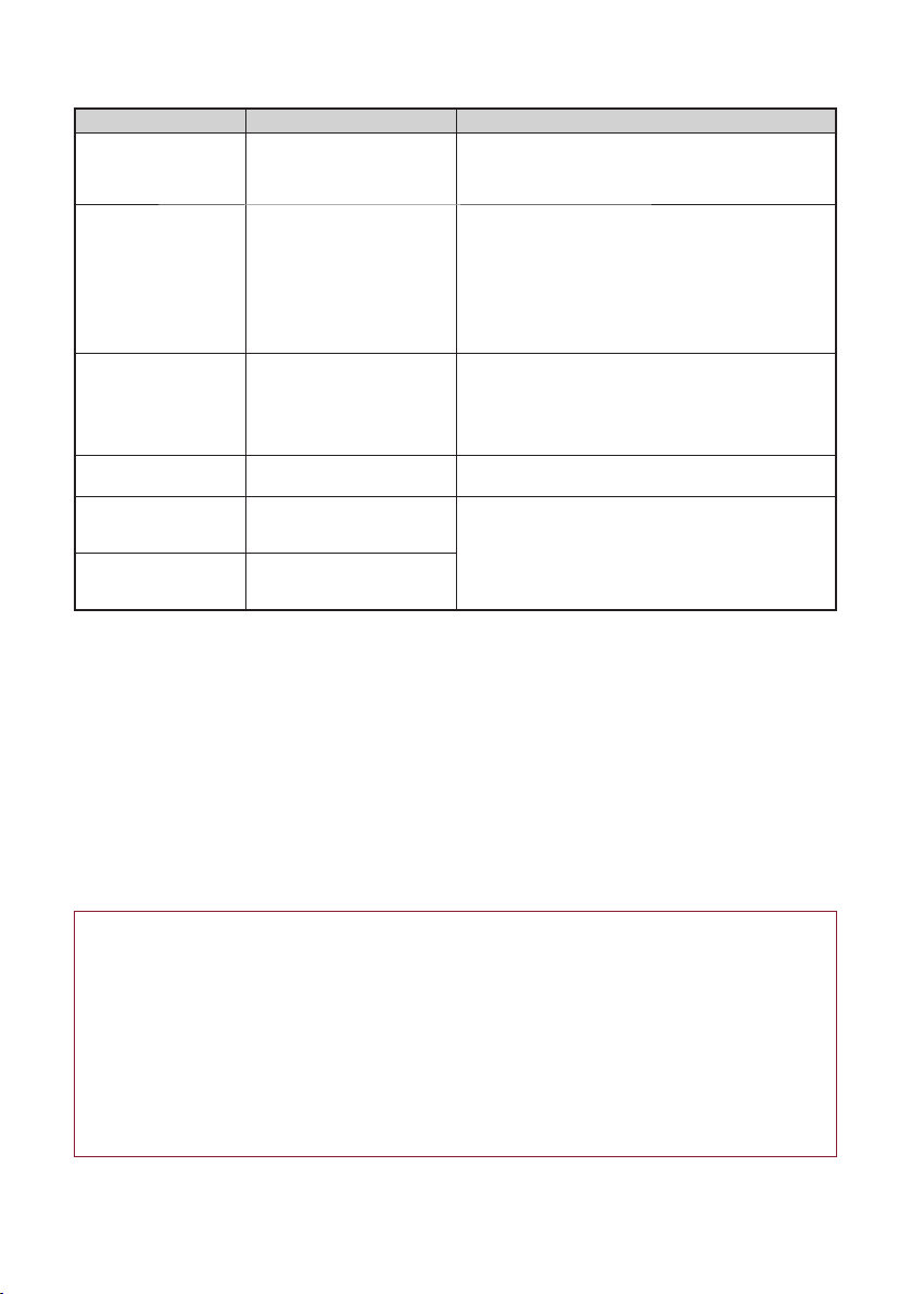
Troubleshooting
Symptom Possible Cause Solution
Gate does not move 1. Minimum number of
entrapment protection
devices not installed
2. Sensors are obstructed
1. Review sensor connections. Slide gate operators require
a minimum of two external monitored devices; one in the
close and one in the open direction.
2. Check for obstructions.
RECEIVER:
Solid Red LED
1. Sensors are not aligned
2. Sensors are too far apart
3. Sensor lenses are dirty
4. Object is obstructing beam
5. Condensation on sensor
lenses
6. Sensor has adapted to short
range use but is installed in a
long range application.
1. Align the sensors until the blue light is solid
2. Decrease the distance between the sensors. NOTE:
Sensors must be 3 ft. (.9 m) - 90 ft. (27.4 m) apart.
3. Gently clean the sensors with a soft damp towel
4. Remove any objects obstructing beam
5. Gently clean the sensors with a soft towel; make sure
sensor heaters are connected.
6. Follow the instructions in the Reset Range Mode section
to reset sensor.
RECEIVER:
Blinking Blue LED
1. Sensors are not optimally
aligned
2. Sensors are too far apart or
too close together
3. Sensor lenses are dirty
1. Align the sensors until the blue light on the receiver is
solid
2. Adjust the distance between the emitter and receiver.
NOTE: Sensors must be 3 ft. (.9 m) - 90 ft. (27.4 m)
apart.
3. Gently clean the sensors with a soft damp towel
EMITTER and RECEIVER:
Blinking Red LED
Incorrect wiring Check for proper connection of sensor wiring. If the issue
continues, replace sensor.
EMITTER or RECEIVER:
Red/Blue LEDs blinking
together
Internal memory fault
Disconnect all power, wait 15 seconds, then reconnect
power. If issue continues, replace sensor.
EMITTER or RECEIVER:
Red/Blue LEDs alternate
blinking
Internal fault
Accessories
LMSGBP: Photoelectric sensor gang box plate
LMEHUL: Photoelectric sensor extended hood further enhances reliability in extreme weather conditions
APOW1: Plug in transformer
Warranty
LiftMaster
®
warrants to the fi rst consumer purchaser of this product that it is free from defect in materials and/
or workmanship for a period of 2 years from the date of purchase.
Loading ...
Loading ...
Loading ...