Loading ...
Installation
IMPORTANT: Disconnect ALL power to the operator.
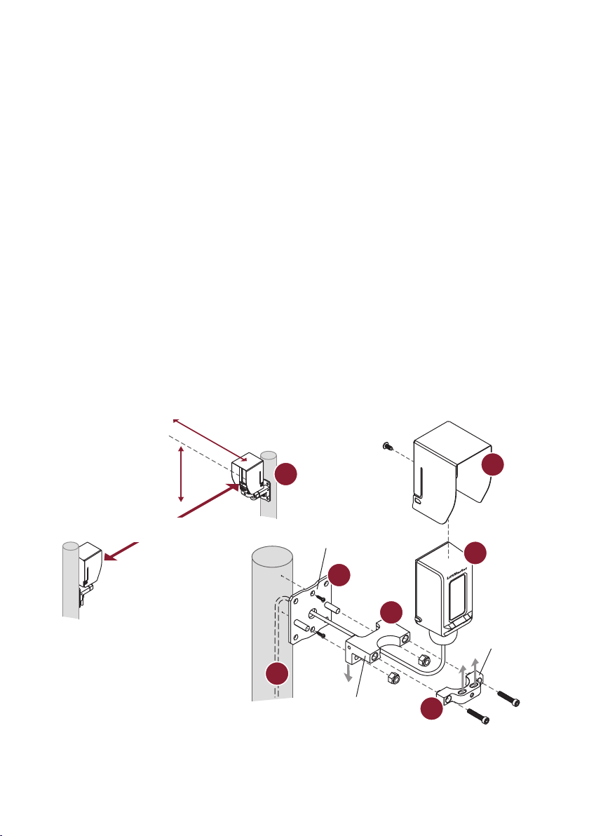
1. Determine the mounting locations for the sensors following the measurements below. If installing
multiple sensors in close proximity, mount the emitters on opposite sides to avoid crosstalk. The receiver
and emitter can be identifi ed by the labels on the back.
2. Attach the mounting bracket to the post with 1/4"-20 screws. Drill a hole in the post through the center
hole in the bracket. Optional: If installing to a square post or fl at surface, you may attach the sensor
bracket directly to the post without using the mounting bracket.
3. Slide the bottom sensor bracket onto the studs of the mounting bracket and secure with 1/4"-20 lock
nuts. Make sure the bracket legs are facing down.
4. Loosely attach the top sensor bracket with 10-32x1" thread-locking screws. Make sure the slots are facing
up.
5. Place the sensor in the bracket and tighten the screws just enough to allow the sensor to rotate inside the
bracket.
6. Slide the hood over the sensor until it snaps into place. Secure hood with the M3 screw.
7. Route wires through the center hole of the mounting bracket and into the post. Optional: Use conduit
with NEMA 4X compatible 1/2"-14 NPT fi tting (not provided).
Carton Inventory
• Emitter with hood and bracket
• Receiver with hood and
bracket
• Wire covers (2)
• Screws 8-32x3/8" (4)
• Screws 1/4"-20x1-1/4" (8)
• Lock nuts 1/4"-20 (4)
• Thread-locking screws
10-32x1" (4)
• M3 screw (2)
• Set screw 10-32x3/8" (2)
• 5/32 Allen key
• 3/32 Allen key
Tools Needed
• Philips screwdriver
• 7/16" socket
2
3
4
5
6
7
1
Distance from ground:
For gate operators:
4" (10.2 cm)-26" (66 cm)
For door operators:
4-1/2" (11.4 cm)
Mounting
bracket
Bottom sensor
bracket
Top sensor
bracket
Distance from gate or wall:
≤ 5" (12.7 cm)
Illustrations are for reference only;
your application may look different.
Distance between sensors:
3 ft. (.9 m)-90 ft. (27.4 m)
Loading ...
Loading ...
Loading ...