Loading ...
Loading ...
Loading ...
Alignment
Reconnect power to the operator.
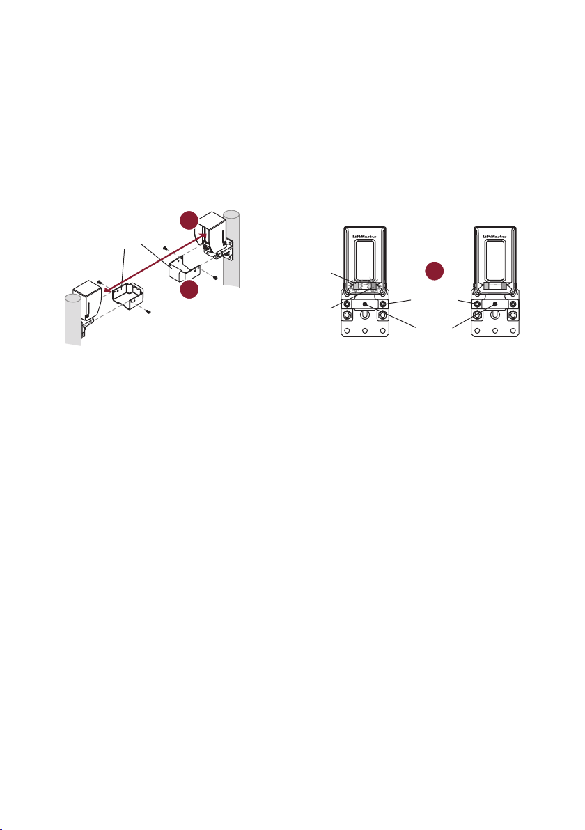
1. Align the sensors. The LEDs on the RECEIVER indicate alignment. The red LED indicates misalignment or
blocked sensor. The blue LED indicates signal strength. Slow blinking indicates weak signal. Fast blinking
indicates stronger signal. Solid blue LED on the receiver indicates optimal alignment. NOTE: Solid blue
LED on the EMITTER indicates the sensor is powered.
2. When the sensors are optimally aligned, tighten the sensor bracket screws to secure the sensors in place
(about 24in-lb of torque). For extra security, tighten with the set screw until it grips the sensor.
3. Place the wire covers onto the sensor brackets. Make sure the tabs on the wire cover slide into the slots
on the sensor bracket. Secure the wire covers with 8-32x3/8" screws. Wire covers are NOT intended for
use with conduit installations.
Test
Test ALL installed sensors for proper operation. Place an obstruction in the path of the beam while the gate is
in motion. The operator will reverse direction of the gate and then stop. If the gate does not stop and reverse,
refer to Troubleshooting below. Perform the test with the obstruction in three locations:
• Halfway between the emitter and receiver
• Near the receiver
• Near the emitter
Reset Range Mode
The sensors automatically adapt to the distance they are installed from each other. The installed range is saved
to memory, optimizing performance for the installation environment. If the installation environment changes in
a way that reduces the beam strength (longer range for example), it may be necessary to reset the sensors so
they can learn the new environment.
To reset the sensors:
1. Disconnect power to the sensors for 5 seconds or longer (disconnect black and red wires or power down
the operator).
2. Reconnect power to the sensors.
3. Block and clear the beam 10 times within 30 seconds of power up. The receiver may indicate the beam is
blocked (solid red LED), but if the emitter and receiver are visually aligned, continue with the procedure.
4. The red and blue LEDs on the receiver will blink together rapidly for 2 seconds indicating sensors are
reset.
5. The sensors will then learn the new installed range and save it to memory.
2
1
3
Set
screw
Wire Cover
Receiver Emitter
Sensor
bracket
screw
Solid blue LED =
optimal alignment
Red LED =
misaligned or
blocked sensor
Loading ...
Loading ...
Loading ...