Your generator requires some assembly and is ready for use after it has been properly serviced with the recommended oil and fuel.
If you have any problems with the assembly of your generator, please call the generator helpline at (800) 743-4115. If calling for assistance, please have the model, revision, and serial number from the identification label available. See Controls and Features for identification label location.
Unpack Generator
Set the carton on a rigid, flat surface.
Remove everything from carton except generator.
Open carton completely by cutting each corner from top to bottom.
Leave generator on carton to install wheel kit.
Shipment Contents
The generator is supplied with:
Engine oil
Operator's manual
Battery float charger
Battery charge cables
Wheel kit
120/240 Volt, 30 Amp locking plug
120 Volt, 30 Amp locking plug
Install Wheel Kit
NOTICE Wheel kit is not intended for over-the-road use.
You will need the following tools to install these components:
3/8” and 13 mm wrench
Socket wrench with a 3/8” and a 13 mm socket
Pliers
Safety glasses
Install the wheel kit as follows:
Tip generator so that engine end is up.
Slide axle (A) through both mounting brackets.
Slide a wheel (B) over axle. NOTICE Be sure to install wheel with raised hub inboard.
Place a washer (CG) on axle and then place an e-ring (D) in axle groove
Install e-ring with pliers, squeezing from top of e-ring to bottom of axle.
Repeat steps 3 through 5 to secure second wheel.
Tip generator so that engine side is down.
Attach clamps (E) to brackets (F) on both sides of generator with 1/4 - 20 hex screws (G).
Repeat steps 2 through 5 to secure the third and fourth wheels.
Attach handles (H) to brackets on generator frame as shown, with 45 mm capscrews (J), flat washers (K), nylon washers (L), and M8 lock nuts (M).
Return generator to normal operating position (resting on wheels).
To apply brakes, push down firmly on handle of both clamps until it locks in the down position and engages the wheels. NOTICE The generator is designed to be used on level surfaces. Always face generator and push to desired location.
Loop handle pins (N) on generator frame just above handle brackets.
Raise handles and insert handle pins to move generator.
To release brakes, pull up on handle of both clamps until it locks in the up position.
Attach Negative Battery Cable
Your unit is equipped with electric start capability but can be started manually. If you choose not to use the electric start feature, you do not need to connect the negative battery cable.
The sealed battery on the generator pre-installed except for the negative (black) battery cable.
To install:
Cut off tie wrap securing loose end of negative (black) cable.
Using an 8 mm or 5/16” socket wrench, remove screw (A), lock washer (B) and flat washer (C) on negative battery terminal.
Slide lock washer, flat washer and negative battery cable (D) over screw as shown.
Reattach screw to negative battery terminal and tighten.
Verify that connections to battery and generator are tight and secure.
NOTICE If your battery is discharged, charge prior to use following the instructions in the section Battery Charger.
Add Engine Oil
Place generator on a flat, level surface.
Clean area around oil fill and remove yellow oil fill cap.
Using oil funnel (optional), slowly pour contents of provided oil bottle into oil fill opening to the “Full” mark on dipstick.
Replace oil fill cap and fully tighten.
NOTICE |mproper treatment of generator could damage it and shorten its life.
*DO NOT attempt to crank or start the engine before it has been properly serviced with the recommended oil. This could result in an engine failure.
Add Fuel
Fuel must meet these requirements:
Clean, fresh, unleaded gasoline.
A minimum of 87 octane/87 AKI (91 RON). For high altitude use, see High Altitude.
Gasoline with up to 10% ethanol (gasohol) is acceptable.
NOTICE Use of unapproved fuels could damage generator and voids warranty.
DO NOT use unapproved gasoline such as E15 and E85.
DO NOT mix oil in gasoline or modify engine to run on alternate fuels.
To protect the fuel system from gum formation, mix in a fuel stabilizer when adding fuel. See Storage. All fuel is not the same. If you experience starting or performance problems after using fuel, switch to a different fuel provider or change brands. This engine is certified to operate on gasoline. The emission control system for this engine is EM (Engine Modifications).
Clean area around fuel fill cap, remove cap.
Slowly add unleaded gasoline (A) to fuel tank (B). Be careful not to fill above the baffle (C). This allows adequate space for fuel expansion as shown.
Install fuel cap and let any spilled fuel evaporate before starting engine.
High Altitude
At altitudes over 5,000 feet (1524 meters), a minimum 85 octane / 85 AKI (89 RON) gasoline is acceptable. To remain emissions compliant, high altitude adjustment is required. Operation without this adjustment will cause decreased performance, increased fuel consumption, and increased emissions. See a Briggs & Stratton Authorized Dealer for high altitude adjustment information. Operation of the engine at altitudes below 2,500 feet (762 meters) with the high altitude kit is not recommended.
System Ground
The generator has a system ground that connects the generator frame components to the ground terminals on the AC output receptacles. The system ground is connected to the AC neutral wire (the neutral is bonded to the generator frame).
Special Requirements
There may be Federal or State Occupational Safety and Health Administration (OSHA) regulations, local codes, or ordinances that apply to the intended use of the generator. Please consult a qualified electrician, electrical inspector, or the local agency having jurisdiction:
In some areas, generators are required to be registered with local utility companies.
If the generator is used at a construction site, there may be additional regulations which must be observed.
Connecting to a Building's Electrical System
Connections for standby power to a building's electrical system must use a listed transfer switch installed by a current licensed electrician. The connection must isolate the generator power from the utility power and must comply with all applicable laws and electrical codes.
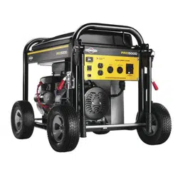
Features and Controls
A - Battery Float Charger Jack — Use battery float charger jack to keep the starting battery charged and ready for use.
B - Hour Meter — Displays and records how many hours your generator has run (up to 9,999.9).
C - 12 Volt DC Receptacle — Use this receptacle with battery charge cables to charge a 12 Volt battery.
D - Start Switch — Push to start the engine.
E - Oil Fill Cap /Dipstick — Check and add engine oil here. used to supply electrical power for the operation of
H - 120 Volt AC, 30 Amp Locking Receptacle — May be used to supply electrical power for the operation of 120 Volt AC, 30 Amp, single phase, 60 Hz electrical lighting, appliance, tool and motor loads.
F - Oil Drain Plug — Drain engine oil here.
G - 120 Volt AC, 20 Amp Duplex Receptacle — May be used to supply electrical power for the operation of 120 Volt AC, 20 Amp, single phase, 60 Hz electrical lighting, appliance, tool and motor loads.
J - Grounding Fastener — If required, please consult a qualified electrician, electrical inspector, or local agency having jurisdiction.
K - 120/240 Volt AC, 30 Amp Locking Receptacle — May be used to supply electrical power for the operation of 120 and/or 240 Volt AC, 30 Amp, single phase, 60 Hz electrical lighting, appliance, tool and motor loads.
L - Identification Label — Provides model, revision and serial number of generator. Please have these readily available if calling for assistance.
M - GFCI Circuit Breaker — A GFCI circuit breaker is provided to protect against electrical ground fault and protect the generator against electrical overload.
N - Spark Arrester Muffler — Exhaust muffler lowers engine noise and is equipped with a spark arrester screen.
P - Engine Identification (stamped on side of valve cover)— Provides model, type and code of engine. Please have these readily available if calling for assistance.
R - Air Cleaner — Protects engine by filtering dust and debris out of intake air.
S - Recoil Starter — Used to start the engine.
T - Rocker Switch — Set this switch to on (I) before starting engine. Set switch to off (0) to turn off engine.
U - Choke Lever — Used when starting a cold engine.
V - Fuel Valve — Used to turn fuel supply on and off to engine.
W - Fuel Tank — Capacity of seven (7) U.S. gallons.
Cord Sets and Receptacles
Use only high quality, well-insulated, grounded extension cords with the generator's 120 Volt duplex receptacle.
Inspect extension cords before each use.
Check the ratings of all extension cords before you use them. Extension cord sets used should be rated for 125 Volt AC loads at 20 Amps or greater for most electrical devices. Some devices, however, may not require this type of extension cord. Check the operator's manuals of those devices for the manufacturer's recommendations.
120 Volt AC, 30 Amp, Locking Receptacle
Use a NEMA L14-30 plug with this receptacle. Connect a 4-wire cord set rated for 250 Volt AC loads at 30 Amps (or greater). You can use the same 4-wire cord if you plan to run a 120 Volt load.
This receptacle powers 120/240 Volt AC, 60 Hz, single phase loads requiring up to 5,000 watts of power (5.0 kW) at 20.8 Amps for 240 Volts or two independent 120 Volt loads at 20.8 Amps each. The outlet is protected by a 2 pole GFCI circuit breaker.
120 Volt AC, 30 Amp Locking Receptacle
Use a NEMA L5-30 plug with this receptacle. Connect a 3-wire cord set rated for 125 Volt AC loads at 30 Amps to the plug.
Use this receptacle to operate 120 Volt AC, 60 Hz, single phase loads requiring up to 2,500 watts (2.5 kW) of power at 20.8 Amps. The outlet is protected by a 2 pole GFCI circuit breaker.
120 Volt AC, 20 Amp, Duplex Receptacle
The duplex receptacle is protected against overload by a 2 pole GFCI circuit breaker.
Use receptacle to operate 120 Volt AC, single-phase, 60 Hz electrical loads requiring up to 2,400 watts (2.4 kW) at 20 Amps of current. Use cord sets that are rated for 125 Volt AC loads at 20 Amps (or greater). Inspect cord sets before each use.
12 Volt DC, 10 Amp Receptacle
This receptacle allows you to recharge a 12 Volt automotive or utility style storage battery with the battery charge cables provided.
This receptacle can not recharge 6 Volt batteries and can not be used to crank an engine having a discharged battery. See the section Charging a Battery before attempting to recharge a battery.
Ground Fault Protection
This unit is equipped with a Ground Fault Circuit Interrupter (GFCI). This device meets applicable federal, state and local codes.
The GFCI protects against electrical shock that may be caused if your body becomes a path which electricity travels to reach ground. This could happen if you touch a “Live” appliance or wire, or are touching plumbing or other materials that connect to the ground.
When protected by a GFCI, one may still feel a shock, but the GFCI should cut current off quickly enough so that a person in normal health should not suffer any serious electrical injury.
Test GFCI Circuit Breaker
Test your GFCI circuit breaker every month, as follows:
While generator is running, push white “Test” button. The circuit breaker should trip (handle will move to approximate center position), which will disconnect power to outlets.
If handle moves to center, reset circuit breaker by firmly moving handle to “Off” (down) position, then to “On” (up) position.
During Generator Use
If circuit breaker trips during use, it usually indicates faulty electrical equipment or cords. However, test the circuit breaker as follows;
Disconnect loads, reset and test circuit breaker as described earlier. Let generator run without any loads for 1 minute.
If circuit breaker tests correctly, the electrical equipment or extension cords may be faulty. Replace faulty electrical equipment and cords before further use.
NOTICE If circuit breaker tests correctly:
Have qualified personnel check all electrical equipment and cords for any defects.
Replace electrical equipment and cords or take to a qualified repair center.
Battery Charger
Use battery float charger jack to keep the starting battery charged and ready for use. Battery charging should be done ina dry location, such as inside a garage.
Plug charger into unit's “Battery Float Charger” jack, which is located on the control panel. Plug battery charger into a 120 Volt AC wall receptacle.
Unplug charger from unit and wall outlet when generator is being started and while it is in operation.
Keep this charger plugged in when generator is not in use to prolong battery life. The charger has a built in float equalizer and will not overcharge the battery, even when plugged in for an extended period of time.
NOTICE See Battery Maintenance for additional information.
Operation
Starting the Engine
NOTICE Always unplug the battery float charger before starting the generator.
Disconnect all electrical loads from the generator. Use the following start instructions:
1. Make sure unit is on a level surface.
NOTICE Failure to start and operate the unit on a level surface will cause the unit not to start or shut down during operation.
2. Turn the fuel valve (A) to the “On” position.
3. Push engine rocker switch to on position (1).
4. Push choke lever (B) to “Choke” position.
5A. For electric starting, push and hold the start switch in “Start” position until generator starts. To prolong the life of starter components, DO NOT hold start switch in “Start” position for more than 5 seconds, and pause for at least 1 minute between starting attempts.
If engine starts, proceed to step 7.
If engine fails to start, proceed to step 6.
NOTICE If battery is discharged, use manual starting instructions.
5B. For manual starting, grasp recoil handle and pull slowly until slight resistance is felt. Then pull rapidly one time only to start engine.
If engine starts, proceed to step 7.
If engine fails to start, proceed to step 6.
6. Move choke lever to “Half” choke position, and pull recoil handle twice or push and hold the start switch in the “Start” position as described in step 5A.
If engine fails to start, repeat steps 4 thru 5.
7. Slowly move choke lever to “Run” position. If engine falters, move choke lever to “Half” choke position until engine runs smoothly, and then to “Run” position.
NOTICE If engine floods, push choke handle all the way in and crank until engine starts.
NOTICE If engine starts after 3 pulls but fails to run, or if unit shuts down during operation, make sure unit is on a level surface and check for proper oil level in crankcase. This unit may be equipped with a low oil protection device. If so, oil must be at proper level for engine to start.
Connecting Electrical Loads
Let engine stabilize and warm up for a few minutes after starting.
Plug in and turn on the desired 120 and/or 240 Volt AC, single phase, 60 Hz electrical loads.
Stopping the Engine
Turn OFF and unplug all electrical loads from generator panel receptacles. NEVER start or stop engine with electrical devices plugged in and turned ON.
Let engine run at no-load for several minutes to stabilize internal temperatures of engine and generator.
Push engine rocker switch to stop position (0).
Move fuel valve to “Off” position.
Oil Pressure Shutdown
If engine oil pressure drops below a preset level, an oil switch will stop the engine. Check oil level with dipstick.
If oil level is hetween ADD and FULL mark on dipstick:
DO NOT try to restart the engine.
Contact a Briggs & Stratton Authorized Dealer.
DO NOT operate engine until oil pressure is corrected.
If oil level is helow ADD mark on dipstick:
Add oil to bring level to FULL mark.
Restart engine and if the engine stops again a low oil pressure condition may still exist. DO NOT try to restart the engine.
Contact a Briggs & Stratton Authorized Dealer.
DO NOT operate engine until oil pressure is corrected.
Charging a Battery
Your generator has the capability of recharging a discharged 12 Volt automotive or utility style storage battery.
DO NOT use the unit to charge any 6 Volt batteries.
DO NOT use the unit to crank an engine having a discharged battery.
To recharge 12 Volt batteries, proceed as follows:
Check fluid level in all battery cells. If necessary, add ONLY distilled water to cover separators in battery cells. DO NOT use tap water.
If battery is equipped with vent caps, make sure they are installed and are tight.
If necessary, clean battery terminals.
Connect battery charge cable connector plug to panel receptacle identified by the words “12V 10A D.C.”
Connect battery charge cable clamp with red handle to the positive (+) battery terminal.
Connect battery charge cable clamp with black handle to the negative (-) battery terminal.
Start engine. Let engine run while battery recharges.
When battery has charged, shut down engine.
NOTICE Use an automotive hydrometer to test battery state of charge and condition. Follow the hydrometer manufacturer's instructions carefully. Generally, a battery is considered to be at 100% state of charge when specific gravity of its fluid (as measured by hydrometer) is 1.260 or higher.
Maintenance
Maintenance Schedule
Follow the hourly or calendar intervals, whichever occurs first. More frequent service is required when operating in adverse conditions noted below.
First 5 Hours
Change engine oil
Every 8 Hours or Daily
Clean debris
Check engine oil level
Every 25 Hours or Yearly
Service engine air cleaner pre-filter'
Every 50 Hours or Yearly
Change engine oil’
Every 100 Hours or Yearly
Service engine air cleaner paper filter’
Service fuel filter
Service spark plug
Inspect muffler and spark arrester
Clean cooling system’
Every 250 Hours or Yearly
Check valve clearance
General Recommendations
Regular maintenance will improve the performance and extend the life of the generator. See any authorized dealer for service.
The generator's warranty does not cover items that have been subjected to operator abuse or negligence. To receive full value from the warranty, the operator must maintain the generator as instructed in this manual.
Some adjustments will need to be made periodically to properly maintain your generator.
All service and adjustments should be made at least once gach season. Follow the requirements in the Maintenance Schedule chart above.
NOTICE Once a year you should clean or replace the spark plug and replace the air filter. A new spark plug and clean air filter assure proper fuel-air mixture and help your engine run better and last longer.
Emissions Control
Maintenance, replacement, or repair of the emissions control devices and systems may he performed hy any non-road engine repair establishment or individual.
However, to obtain “no charge” emissions control service, the work must be performed by a factory authorized dealer. See the Emissions Warranty.
Generator Maintenance
Generator maintenance consists of keeping the unit clean and dry. Operate and store the unit in a clean dry environment where it will not be exposed to excessive dust, dirt, moisture, or any corrosive vapors. Cooling air slots in the generator must not become clogged with snow, leaves, or any other foreign material.
NOTICE DO NOT use water or other liquids to clean generator. Liquids can enter engine fuel system, causing poor performance and/or failure to occur. In addition, if liquid enters generator through cooling air slots, some of the liquid will be retained in voids and cracks of the rotor and stator winding insulation. Liquid and dirt buildup on the generator internal windings will eventually decrease the insulation resistance of these windings.
Cleaning
Daily or before use, look around and underneath the generator for signs of oil or fuel leaks. Clean accumulated debris from inside and outside the generator. Keep the linkage, spring and other engine controls clean. Keep the area around and behind the muffler free from any combustible debris. Inspect cooling air slots and openings on generator. These openings must be kept clean and unobstructed.
Engine parts should be kept clean to reduce the risk of overheating and ignition of accumulated debris:
Use a damp cloth to wipe exterior surfaces clean.
NOTICE Improper treatment of generator could damage it and shorten its life.
DO NOT expose generator to excessive moisture, dust, dirt, or corrosive vapors.
DO NOT insert any objects through cooling slots.
Use a soft bristle brush to loosen caked on dirt or cil.
Use a vacuum cleaner to pick up loose dirt and debris.
Battery Maintenance
Other than float charging, described elsewhere, no maintenance is required for the starting battery. Keep the battery and terminals clean and dry.
NOTICE Battery charging should be performed in a dry location, such as inside a garage.
Fuel Valve Maintenance
The fuel valve is equipped with a fuel sediment cup, screen, retaining ring and o-ring that need to be cleaned.
1. Move fuel valve to “Off” position.
2. Remove sediment cup (A) from fuel valve. Remove o-ring (B), retaining ring (C) and screen (D) from fuel valve.
3. Wash sediment cup, o-ring, retaining ring, and screen in a nonflammable solvent. Dry them thoroughly.
4. Place screen, retaining ring, and o-ring into fuel valve. Install sediment cup and tighten securely.
5. Move fuel valve to “On” position, and check for leaks. Replace o-ring if there is any leakage.
Engine Maintenance
Oil Recommendations
We recommend the use of Briggs & Stratton Warranty Certified oils for best performance. Other high-quality detergent oils are acceptable if classified for service SF, SG, SH, SJ or higher. DO NOT use special additives.
Outdoor temperatures determine the proper oil viscosity for the engine. Use the chart to select the best viscosity for the outdoor temperature range expected.
Checking Oil Level
Oil level should be checked prior to each use or at least every 8 hours of operation. Keep oil level maintained.
Make sure generator is on a level surface.
Clean area around oil fill, remove oil cap/dipstick and wipe dipstick with clean cloth. Replace dipstick. Remove and check oil level.
Verify oil is at “Full” mark on dipstick. Replace and tighten oil cap/dipstick.
Adding Engine Oil
Make sure generator is on a level surface.
Check oil level as described in Checking Oil Level.
If needed, slowly pour oil into oil fill opening to the "Full” mark on dipstick. DO NOT overfill.
Replace and tighten oil cap/dipstick.
Changing Engine Oil
If you are using your generator under extremely dirty or dusty conditions, or in extremely hot weather, change the oil more often.
KEEP OUT OF REACH OF CHILDREN. DON'T POLLUTE. CONSERVE RESOURCES. RETURN USED OIL TO COLLECTION CENTERS.
Change the oil while the engine is still warm from running, as follows:
1. Make sure unit is on a level surface.
2. Disconnect the spark plug wire from the spark plug and place the wire where it cannot contact spark plug.
3. Clean area around oil drain plug (A). The oil drain plug is located at base of engine, under recoil.
4. Remove oil drain plug and drain oil completely into a suitable container.
6. Slowly pour recommended oil (about 28 oz.) into oil fill opening. Pause to permit oil to settle. Fill to “Full” mark on dipstick.
7. Wipe dipstick clean each time oil level is checked. DO NOT overfill.
8. Reinstall cil cap/dipstick. Tighten cap securely.
9. Wipe up any spilled oil.
Service Air Cleaner
Your engine will not run properly and may be damaged if you run it with a dirty air cleaner. Clean or replace more often if operating under dusty or dirty conditions.
To service the air cleaner, follow these steps:
1. Loosen screws (B) and remove air cleaner cover (CG).
2. Carefully remove foam pre-filter (D) and paper filter (E).
3. Wipe clean inside of base (F) and cover thoroughly.
4. Clean or replace the foam pre-filter. To clean, wash pre- filter in a solution of household detergent and warm water, then rinse thoroughly. Squeeze dry in a clean cloth.
5. Clean paper filter by tapping it gently on a solid surface. If the paper filter is too dirty, replace it with a new one. Dispose of the old filter properly.
6. Insert the foam pre-filter into the air cleaner cover, then the paper filter.
7. Assemble air cleaner cover onto base and tighten screws.
Service Spark Plug
Changing the spark plug will help your engine to start easier and run better.
Clean area around spark plug.
Remove and inspect spark plug.
Replace spark plug if electrodes are pitted, burned or porcelain is cracked. Use the recommended replacement spark plug. See Specifications.
Check electrode gap with wire feeler gauge and reset spark plug gap to recommended gap if necessary (see Specifications).
Install spark plug and tighten firmly.
Inspect Muffler and Spark Arrester
Inspect the muffler for cracks, corrosion, or other damage. Remove the spark arrester, if equipped, and inspect for damage or carbon blockage. If replacement parts are required, make sure to use only original equipment replacement parts.
Clean and inspect the spark arrester as follows:
1. To remove muffler heat shield (A) from muffler (B), remove four screws that connect guard to muffler bracket.
2. Remove four screws that attach spark arrester screen (CG).
3. Inspect screen and obtain a replacement if torn, perforated or otherwise damaged. DO NOT use a defective screen. If screen is not damaged, clean it with commercial solvent.
4. Reattach screen and muffler guard.
Clean Cooling System
Over time debris may accumulate in cylinder cooling fins and cannot be observed without partial engine disassembly. For this reason, we recommend you have an authorized service dealer clean the cooling system (D) per recommended intervals (see Maintenance Schedule in the Maintenance section). Equally important is to keep top of engine free from debris. Also see Cleaning.
Check Valve Clearance
Regular valve clearance check and adjustment will improve performance and extend engine life. This procedure cannot be done without partial engine disassembly and the use of special tools. For this reason we recommend that you have an authorized Service Dealer check and adjust valve clearance at recommended intervals (see Maintenance Schedule in the Maintenance section).
Carburetor Adjustment
The carburetor on this engine is low emission. It is equipped with a non-adjustable idle mixture valve. Top speed has been set at the factory. If adjustment is required, see an authorized service dealer.
Storage
The generator should be started at least once every seven days and allowed to run at least 30 minutes. If this cannot be done and you must store the unit for more than 30 days, use the following guidelines to prepare it for storage.
Generator Storage
Clean the generator as outlined in Cleaning in the Maintenance section.
Check that cooling air slots and openings on generator are open and unobstructed.
Long Term Storage Instructions
Fuel can become stale when stored over 30 days. Stale fuel causes acid and gum deposits to form in the fuel system or on essential carburetor parts. To keep fuel fresh, use Briggs &Stratton® Advanced Formula Fuel Treatment & Stabilizer, available wherever Briggs & Stratton genuine service parts are sold.
For engines equipped with a FRESH START® fuel cap, use Briggs & Stratton FRESH START® available in a drip concentrate cartridge.
There is no need to drain gasoline from the engine if a fuel stabilizer is added according to instructions. Run the engine for 2 minutes to circulate the stabilizer throughout the fuel system before storage.
If gasoline in the engine has not been treated with a fuel stabilizer, it must be drained into an approved container. Run the engine until it stops from lack of fuel. The use of a fuel stabilizer in the storage container is recommended to maintain freshness.
Change Oil
While engine is still warm, drain oil from crankcase. Refill with recommended grade. See Changing Engine Oil in Engine Maintenance.
Other Storage Tips
DO NOT store fuel from one season to another unless it has been treated as described in Long Term Storage Instructions.
Replace fuel can if it starts to rust. Contaminated fuel will cause engine problems.
Cover unit with a suitable protective cover that does not retain moisture.
Store generator in clean, dry area.
Troubleshooting
Problem
Cause
Correction
1. GFCI circuit breakers is open.
1. Reset circuit breaker.
Engine is running, but no AC output is available.
2. Fault in generator.
2. Contact Briggs & Stratton authorized dealer.
3. Poor connection or defective cord set.
3. Check and repair.
4. Connected device is bad.
4. Connect another device that is in good condition.
1. Short circuit in a connected load.
1. Disconnect shorted electrical load.
Engine runs good at no-load but "bogs down" when loads are connected.
2. Engine speed is too slow.
2. Contact Briggs & Stratton authorized dealer.
3. Generator is overloaded.
3. See Don 't Overload Generator.
4. Shorted generator circuit.
4. Contact Briggs & Stratton authorized dealer.
5. Clogged or dirty fuel filter.
5. Clean or replace fuel filter.
1. Engine switch set to off (0) position.
1. Set switch to on (1) position.
2. Fuel valve is in ’Off' position.
2. Turn fuel valve to 'On' position.
3. Low oil level.
3. Fill crankcase to proper level or place generator on level surface.
4. Dirty air cleaner.
4. Clean or replace air cleaner.
5. Clogged or dirty fuel filter.
5. Clean or replace fuel filter.
6. Out of fuel.
6. Fill fuel tank.
7. Stale fuel.
7. Drain fuel tank and carburetor; fill with fresh fuel.
Engine will not start, starts and runs rough or shuts down when running.
8. Spark plug wire not connected to spark plug.
8. Connect wire to spark plug.
9. Bad spark plug.
9. Replace spark plug.
10. Water in fuel.
10. Drain fuel tank and carburetor; fill with fresh fuel.