Loading ...
Loading ...
Loading ...
Installation/Owner's Manual
2-15
2. Installing ACP
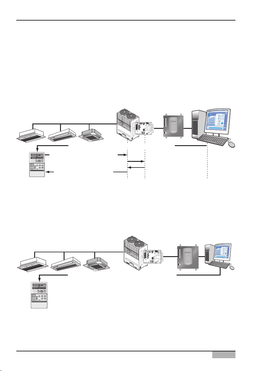
The following figure shows the example of the central control for connecting the 2PIN connector to the
CN_DRY terminal.
1) 'Heating operation, 20°C , Strong wind, Temperature lock' function is ordered by the central control
such as ACP or AC Manager, which is transferred to the remote controller.
2) If the user changes the temperature to 25°C by the remote controller, the related command is
transferred to the outdoor unit and the remote controller displays the 25°C setting.
3) The outdoor unit receives the related command and transferrs it to the PI485.
4)
The PI485 cancels this command and transferrs the previous central control command again. And, the
remote controller displays again the 20°C temperature transferred by the central control command.
On the other hand, let's see an example of connecting the 2PIN connector to CN_DRY terminal.
When a command is given for function of "Heat operation, 20°C setting, high fan level, temperature
lock" through the central control, the applicable command is transmitted through the remote
controller. "HL (Hard Lock)" message showing the central control status is displayed on the remote
controller. If the user sets the temperature to 25°C, the command is blocked at the remote controller.
3) Heating, 25°C, Strong wind
4) Heating, 20°C, Strong wind
ON
L1 2 3 4
KSDO4H
Multi V
2) Change temperature to 25°C
5) Heating, 20°C, Strong wind
6) Return to Heating, 20°C, Strong wind
1) Set ‘Heating, 20°C, Strong wind, Temperature lock’
LG-NET 1
MENU/
SELECT
TX
RX
LG-NET 2
TX
RX
LG-NET 3
TX
RX
LG-NET 4
TX
RX
Ethernet 1
ACT
LNK
Ethernet 2
ACT
LNK
Console
Run
Power
TX
RX
FDD
TX
RX
Ext.
TX
RX
DI
1
2
3
4
5
6
7
8
9
10
11
12
13
14
15
16
17
18
19
20
DO
1
2
3
4
ACP
ON
L1 2 3 4
KSDO4H
Multi V
Set ‘Heating, 20°C, Strong wind, Temperature lock’
The remote controller displays ‘HL’ message
It is not possible for the user to operate.
LG-NET 1
MENU/
SELECT
TX
RX
LG-NET 2
TX
RX
LG-NET 3
TX
RX
LG-NET 4
TX
RX
Ethernet 1
ACT
LNK
Ethernet 2
ACT
LNK
Console
Run
Power
TX
RX
FDD
TX
RX
Ext.
TX
RX
DI
1
2
3
4
5
6
7
8
9
10
11
12
13
14
15
16
17
18
19
20
DO
1
2
3
4
Loading ...
Loading ...
Loading ...