Loading ...
Loading ...
Loading ...
Version - 2/21/2005 17
www.vizioce.com
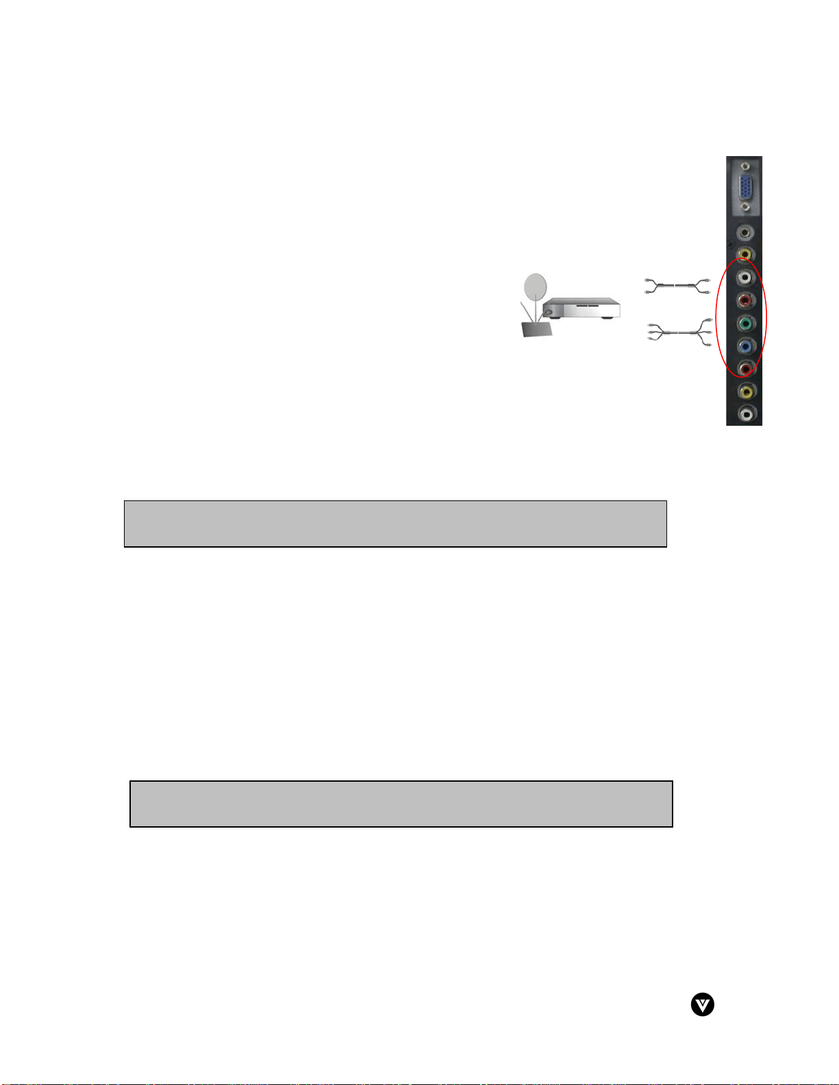
2.3.2 - Using Component Video
Installation:
1. Connect the Y (green color) connector on the rear of
your HDTV set-top box to the corresponding Y (green
color) connector in the AV2 connections (green band)
on the side of your LCD TV.
2. Connect the Pb\Cb (blue color) connector on the rear
of your HDTV set-top box to the corresponding Pb\Cb
(blue color) connector in the AV2 connections (green
band) on the side of your LCD TV.
3. Connect the Pr\Cr (red color) connector on the rear of
your HDTV set-top box to the corresponding Pr\Cr (red
color) connector in the AV2 connections (green band)
on the side of your LCD TV.
4. Connect the R (red color) and L (white color) audio
connectors on the rear of your HDTV set-top box to the
R (red color) and L (white color) audio input connectors
in the AV2 connections (green band) on the rear of
your LCD TV.
5. Turn on the power to the LCD TV and HDTV set-top box.
6. Select Component using the INPUT button on the front of the LCD TV.
2.4 - Connecting Your VCR or Video Camera
Installation:
1. Turn off the power to the LCD TV and VCR or video camera.
2. Connect the S-Video jack on your VCR or video camera to the S-Video jack in the AV1
connections (red band) on the side of your LCD TV.
3. Connect the R (red color) and L (white color) audio connectors on your VCR or video
camera to the R (red color) and L (white color) audio input connectors in the AV1
connections (red band) on the side of your LCD TV.
4. Turn on the power to the LCD TV and VCR or video camera.
5. Select S-Video using the INPUT button on the front of the LCD TV.
Note: Refer to your VCR or video camera user manual for more information about the
video output requirements of the product.
Note: Refer to your HDTV Set-Top Box user manual for more information about the
video output requirements of the product.
Loading ...
Loading ...
Loading ...