Loading ...
Loading ...
Loading ...
19
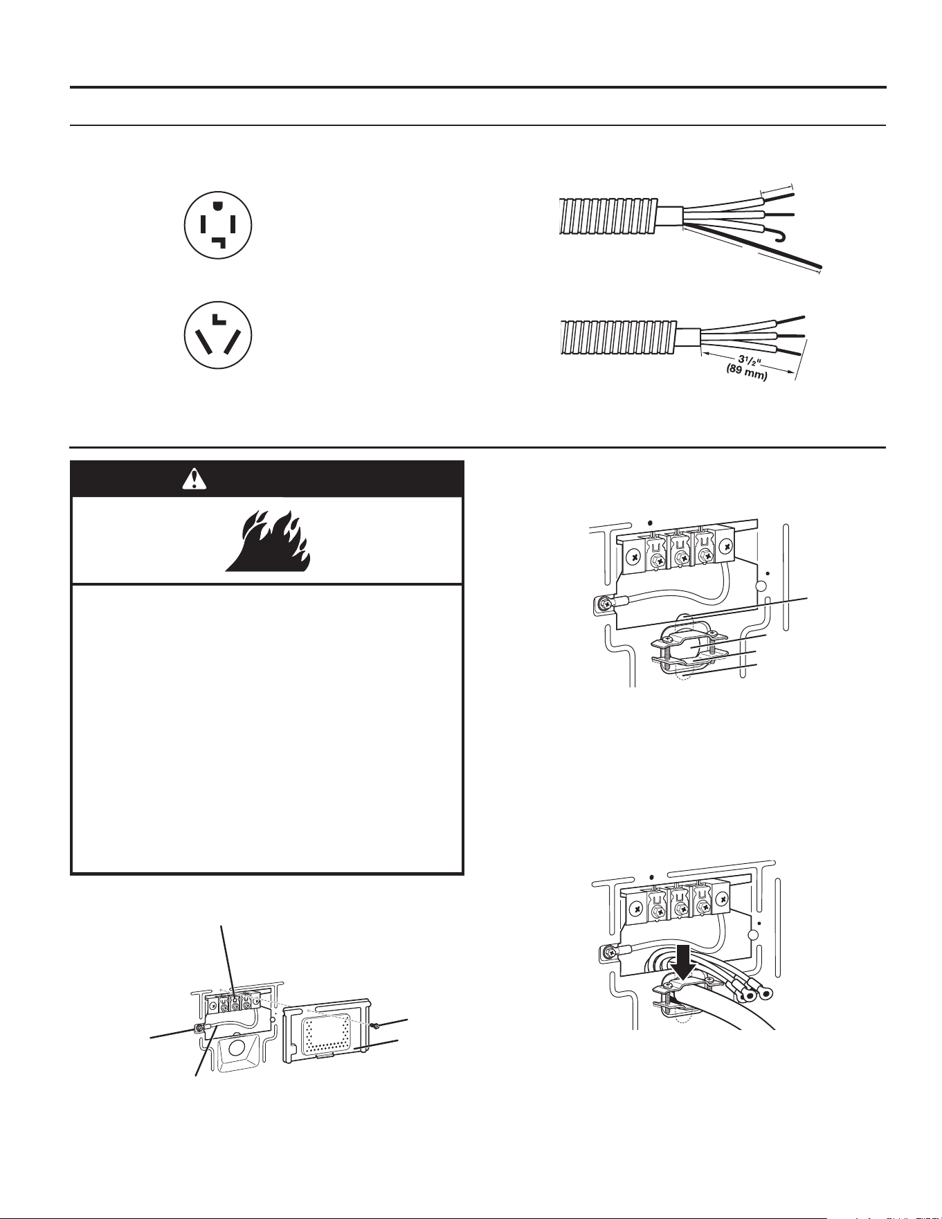
ELECTRIC DRYER ELECTRICAL CONNECTIONS ELECTRIC DRYER ELECTRICAL CONNECTIONS (FOR U.S.A. ONLY)(FOR U.S.A. ONLY)
2. Insert power cord into strain relief.
Remove Terminal Block Cover
Power Supply Cord Connection
Put power supply cord through the strain relief. Be sure that the
wire insulation on the power supply cord is inside the strain relief.
The strain relief should have a tight fit with the dryer cabinet and
be in a horizontal position. Do not further tighten strain relief
screws at this point.
A
B
E
D
C
Power Cord
4-wire receptacle (NEMA Type 14-30R)
Go to “Power Supply Cord Connection” section.
3-wire receptacle (NEMA Type 10-30R)
Go to “Power Supply Cord Connection” section.
Connection Options
Direct Wire
4-wire direct
Go to “Direct Wire Connection” section.
3-wire direct
Go to “Direct Wire Connection” section.
1"
(25 mm)
5"
(127 mm)
NOTE: If local codes do not permit connection of a cabinet-ground conductor to neutral wire, go to “Connecting 3-Wire Connection:
Optional” section. This connection may be used with either a power supply cord or a direct wire connection.
Remove the screws from a 3/4" (19 mm) UL listed strain relief
(UL marking on strain relief). Put the tabs of the two clamp
sections (C) into the hole below the terminal block opening (B) so
that one tab is pointing up (A) and the other is pointing down (D),
and hold in place. Tighten strain relief screws just enough to hold
the two clamp sections (C) together.
Power Supply Cord Strain Relief
1. Insert strain relief.
WARNING
Fire Hazard
Use a new UL listed 30 A power supply cord.
Use a UL listed strain relief.
Disconnect power before making electrical connections.
Connect neutral wire (white or center wire) to center
terminal (silver).
Ground wire (green or bare wire) must be connected to
green ground connector.
Connect remaining 2 supply wires to remaining
2 terminals (gold).
Securely tighten all electrical connections.
Failure to do so can result in death, fire, or
electrical shock.
D
B
A
C
Before you start, disconnect power. Remove hold-down
screw (D) and terminal block cover (A).
A. Terminal block cover
B. External ground conductor screw
C. Center terminal block screw
D. Hold-down screw
E. Neutral ground wire
Loading ...
Loading ...
Loading ...