APPLICATION
The antenna isolation kit protects gate operator components from
possible damage caused by certain wiring configurations. The
installation of some accessories require one of the outputs from
the transformer be shunted to the chassis ground which may blow
the transformer fuse or damage the pre-installed universal
receiver. LiftMaster
®
does NOT recommend connecting the
transformer outputs to the chassis ground, however some third
party accessories require one of the transformer outputs to be
shunted to the chassis ground.
The isolation kit is for use with gate operators models: SL575,
SL585, SL595, HS670, SW420, SW279, and SW490.
CARTON INVENTORY
Nylon Flat Washer. . . . . . . . . . . . . . . . . . . . . . . . . . . . (216A0253)
Nylon Shoulder Washer . . . . . . . . . . . . . . . . . . . . . . . (184A0182)
Fuse . . . . . . . . . . . . . . . . . . . . . . . . . . . . . . . . . . . . . (35-310-032)
Fuse . . . . . . . . . . . . . . . . . . . . . . . . . . . . . . . . . . . (35-310-032-1)
TOOLS NEEDED
• Pliers and wrenches
• Screwdrivers
• Diagonal wire cutters
• Wire strippers
• Drill
• 1/2" drill bit
• Digital voltmeter
DETERMINE IF THE ISOLATION KIT IS NEEDED
To determine if the isolation kit is needed for your installation:
1. Disconnect power to the operator.
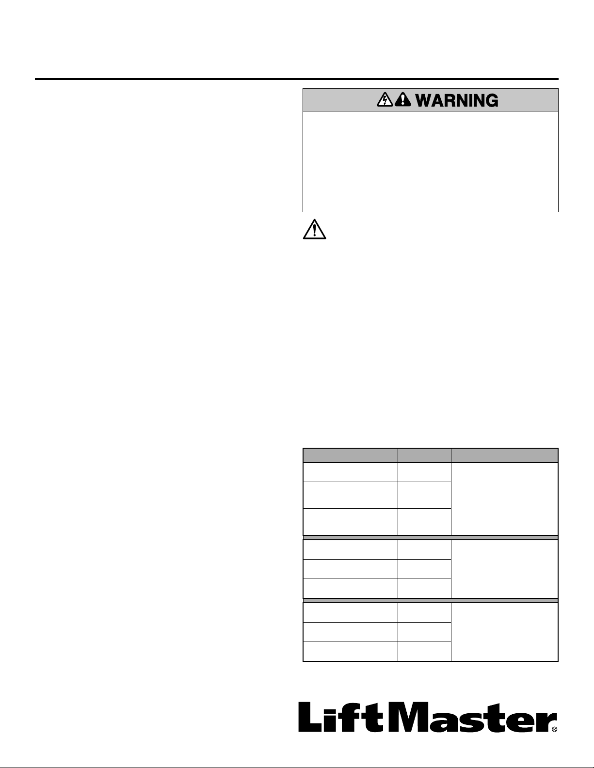
2. Disconnect the universal receiver (model 850LM) from the
operator. Location varies depending on the operator, refer to
the owner’s manual.
3. Connect all other accessories according to the instructions
that came with them.
4. Restore power to the operator.
5. Configure a digital voltmeter to measure AC voltage. Make 3
voltage measurements between the following points: R1-R2,
R1-chassis ground, and R2-chassis ground. Location varies
depending on the operator, refer to the owner’s manual.
If there is no voltage between R1-R2, check to see if the
transformer fuse is blown. If the fuse is blown, replace with
the appropriate fuse included in the kit and measure voltage
again.
6. Refer to the table and follow the instructions indicated by
your set of voltage measurements.
To reduce the risk of SERIOUS INJURY or DEATH:
• Disconnect electric power at the fuse box BEFORE
proceeding.
• ALL electrical connections MUST be made by a qualified
individual.
• Upon completion of kit installation, the area MUST be
cleared and secured. At that time the unit may be returned
to service.
MEASUREMENT POINTS VOLTAGE INSTRUCTIONS
R1-R2 24 VAC Neither of the
transformer outputs are
grounded.
The isolation kit is NOT
needed.
R1-chassis ground Aprox.
14 VAC
R2-chassis ground Aprox.
14 VAC
R1-R2 24 VAC
R1 is shunted to ground.
Proceed to TEST THE
UNIVERSAL RECEIVER
FOR DAMAGE.
R1-chassis ground 0 VAC
R2-chassis ground 24 VAC
R1-R2 24 VAC
R2 is shunted to ground.
Proceed to TEST THE
UNIVERSAL RECEIVER
FOR DAMAGE.
R1-chassis ground 24 VAC
R2-chassis ground 0 VAC
Antenna Isolation Kit
K001A3200-2
WARNING: This product can expose you to chemicals
including lead, which are known to the State of California to
cause cancer or birth defects or other reproductive harm.
For more information go to www.P65Warnings.ca.gov
2
TEST THE UNIVERSAL RECEIVER FOR DAMAGE
You may need to replace the pre-installed universal receiver
(model 850LM). To test the universal receiver for damage:
1. Disconnect power to the operator.
2. Disconnect the universal receiver from the operator.
3. Configure a digital voltmeter to measure resistance.
4. Connect the negative or black lead of the voltmeter to the “F”
connector used to ground the universal receiver antenna.
5. Connect the positive or red lead of the voltmeter to:
a. The + power input of the universal receiver. If the meter
reads (0Ω), there is a short indicating the universal receiver
is damaged. Replace the universal receiver.
b. The - power input of the universal receiver. If the meter
reads (0Ω), there is a short indicating the universal receiver
is damaged. Replace the universal receiver.
NOTE: Don’t confuse 0Ω with ∞Ω.
6. If the voltmeter does not indicate a short, the universal
receiver can be used.
INSTALL THE ISOLATION KIT
To install the isolation kit:
1. Disconnect power to the operator.
2. Remove all accessories from the operator.
3. Locate the chassis-mounted “F” connector (where the coax
antenna passes through the operator chassis). Location
varies depending on the operator, refer to the owner’s
manual.
4. Disconnect the coax cables from both sides of the “F”
connector.
5. Remove the “F” connector and the mounting hardware. Set
aside for reinstallation.
6. Drill out the hole using a 1/2" drill bit.
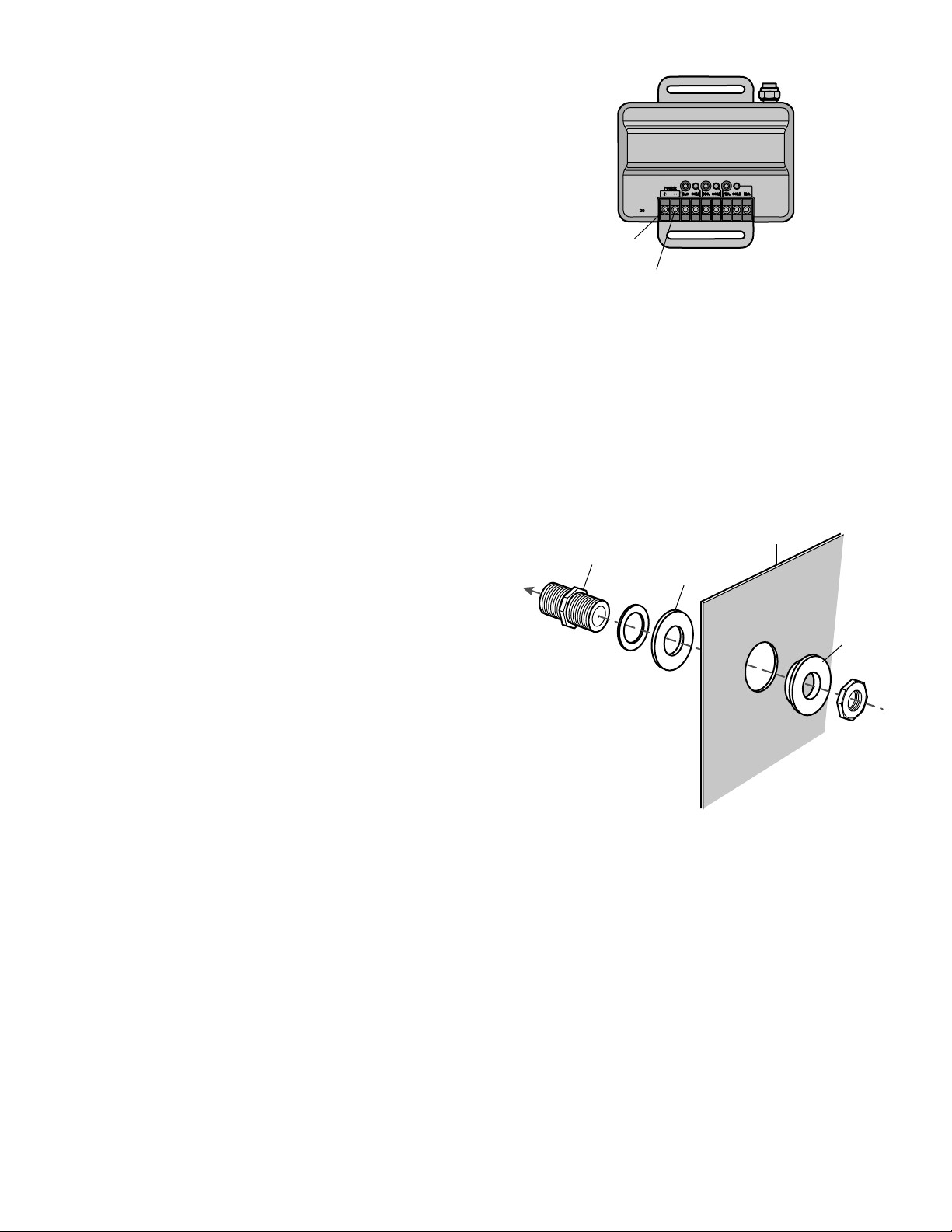
7. Reinstall the “F” connector to the chassis. Insert the isolation
washers between the operator chassis and the other
hardware. The shoulder washer should go on the inside of the
operator. The flat washer should go on the outside of the
operator. See illustration for assembly order.
8. Reconnect the coax cables to the “F” connector.
9. Connect the antenna ground to the chassis.
10. Connect all other accessories according to the instructions
that came with them.
11. Restore power and test the operator.
Chassis
Nylon flat washer
“F” connector
To antenna
Nylon
shoulder
washer
(+) power
input
(-) power
input
APPLICATION
Le nécessaire d’isolation d’antenne protège les composants de
l’actionneur de barrière contre les dommages possibles causés
par certaines configurations de câblage. L’installation de certains
accessoires exige que l’une des sorties du transformateur soit
court-circuitée à la masse du châssis, laquelle peut faire griller le
fusible du transformateur ou endommager le récepteur universel
préinstallé. LiftMaster
®
DÉCONSEILLE de connecter les sorties du
transformateur à la masse du châssis; toutefois, certains
accessoires tiers exigent que l’une des sorties du transformateur
soit court-circuitée à la masse du châssis.
Le nécessaire d’isolation a été prévu pour être utilisé avec les
modèles d’actionneur de barrière suivants : SL575, SL585, SL595,
HS670, SW420, SW279 et SW490.
INVENTAIRE DE L’EMBALLAGE
Rondelle plate en nylon . . . . . . . . . . . . . . . . . . . . . . . (216A0253)
Rondelle à épaulement en nylon . . . . . . . . . . . . . . . . (184A0182)
Fusible . . . . . . . . . . . . . . . . . . . . . . . . . . . . . . . . . . . (35-310-032)
Fusible . . . . . . . . . . . . . . . . . . . . . . . . . . . . . . . . . (35-310-032-1)
OUTILS NÉCESSAIRES
• Pinces et clés
• Tournevis
• Coupe-fils diagonaux
• Pinces à dénuder
• Perceuse
• Mèche de 1/2 po
• Voltmètre numérique
DÉTERMINER SI LE NÉCESSAIRE D’ISOLATION
EST NÉCESSAIRE
Pour déterminer si le nécessaire d’isolation est nécessaire pour
votre installation :
1. Déconnecter l’alimentation à l’actionneur.
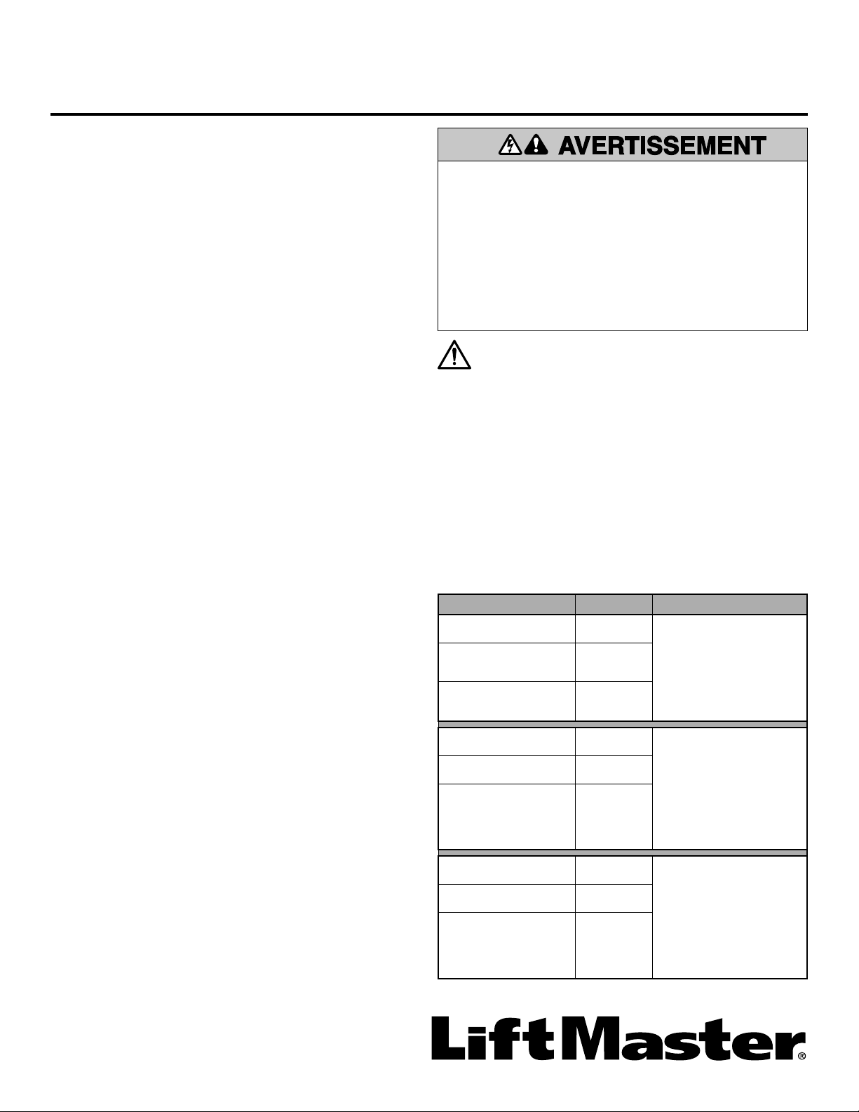
2. Déconnecter le récepteur universel (modèle 850LM) de
l’actionneur. L’emplacement varie en fonction de l’actionneur,
consulter à cet effet le manuel du propriétaire.
3. Connecter tous les autres accessoires conformément aux
instructions qui les accompagnent.
4. Restaurer l’alimentation à l’actionneur.
5. Configurer un voltmètre numérique pour mesurer la tension
c.a. Prendre trois lectures de la tension entre les points
suivants : R1-R2, R1-masse du châssis, et R2-masse du
châssis. L’emplacement varie en fonction de l’actionneur,
consulter à cet effet le manuel du propriétaire.
S’il n’y a aucune tension entre R1-R2, vérifier si le fusible du
transformateur est grillé. Si le fusible est grillé, le remplacer
par le fusible approprié inclus dans le nécessaire et mesurer
de nouveau la tension.
6. Consulter le tableau et suivre les instructions indiquées par
votre ensemble de mesures de tension.
Pour réduire le risque de BLESSURES GRAVES, voire
MORTELLES :
• Déconnecter l’alimentation au niveau de la boîte à fusibles
AVANT de poursuivre.
• TOUTES les connexions électriques DOIVENT être
effectuées par une personne qualifiée.
• Après l’installation du nécessaire d’isolation, la zone DOIT
être dégagée et sécurisée. Ce n’est qu’à ce moment que
l’unité peut être remise en service.
ATTENTION
AVERTISSEMENT
AVERTISSEMENT
AVERTISSEMENT
POINTS DE MESURE TENSION INSTRUCTIONS
R1-R2 24 V c.a. Aucune des sorties du
transformateur n’est
mise à la masse.
Le nécessaire
d’isolation n’est PAS
nécessaire.
R1-masse du châssis Environ
14 V c.a.
R2-masse du châssis Environ
14 V c.a.
R1-R2 24 V c.a.
R1 est court-circuité à la
masse.
Passer à MISE À
L’ESSAI DU RÉCEPTEUR
UNIVERSEL POUR
DÉTECTION DE
DOMMAGE.
R1-masse du châssis 0 V c.a.
R2-masse du châssis 24 V c.a.
R1-R2 24 V c.a.
R2 est court-circuité à la
masse.
Passer à MISE À
L’ESSAI DU RÉCEPTEUR
UNIVERSEL POUR
DÉTECTION DE
DOMMAGE.
R1-masse du châssis 24 V c.a.
R2-chassis ground 0 V c.a.
Nécessaire d’isolation d’antenne
K001A3200-2
AVERTISSEMENT : Ce produit peut vous exposer à des
produits chimiques comme le plomb, reconnu par l’État
de la Californie comme cause de cancers, d’anomalies
congénitales et d’autres problèmes liés à la reproduction.
Pour plus d’informations, visitez www.P65Warnings.ca.gov
4
MISE À L’ESSAI DU RÉCEPTEUR UNIVERSEL
POUR DÉTECTION DE DOMMAGE
Il est possible que vous deviez remplacer le récepteur universel
préinstallé (modèle 850LM). Pour tester le récepteur universel afin
de détecter tout dommage :
1. Déconnecter l’alimentation à l’actionneur.
2. Déconnecter le récepteur universel de l’actionneur.
3. Configurer un voltmètre numérique pour mesurer la
résistance.
4. Connecter la borne négative ou noire du voltmètre au
connecteur « F » utilisé pour mettre à la masse l’antenne du
récepteur universel.
5. Connecter la borne positive ou rouge du voltmètre à :
a. l’entrée d’alimentation + du récepteur universel. Si le
voltmètre lit (0Ω), c’est qu’il y a un court-circuit indiquant
que le récepteur universel est endommagé. Remplacer le
récepteur universel.
b. l’entrée d’alimentation - du récepteur universel. Si le
voltmètre lit (0Ω), c’est qu’il y a un court-circuit indiquant
que le récepteur universel est endommagé. Remplacer le
récepteur universel.
REMARQUE : Ne pas confondre 0Ω et ∞Ω.
6. Si le voltmètre n’indique pas de court-circuit, le récepteur
universel peut être utilisé.
INSTALLER LE NÉCESSAIRE D’ISOLATION
Pour installer le nécessaire d’isolation :
1. Déconnecter l’alimentation à l’actionneur.
2. Déposer tous les accessoires de l’actionneur.
3. Localiser le connecteur « F » monté sur le châssis (où
l’antenne coaxiale passe par le châssis de l’actionneur).
L’emplacement varie en fonction de l’actionneur, consulter à
cet effet le manuel du propriétaire.
4. Déconnecter les câbles coaxiaux des deux côtés du
connecteur « F ».
5. Déposer le connecteur « F » et la visserie de montage. Les
mettre de côté pour la réinstallation.
6. Percer un trou à l’aide d’une mèche de 1/2 po.
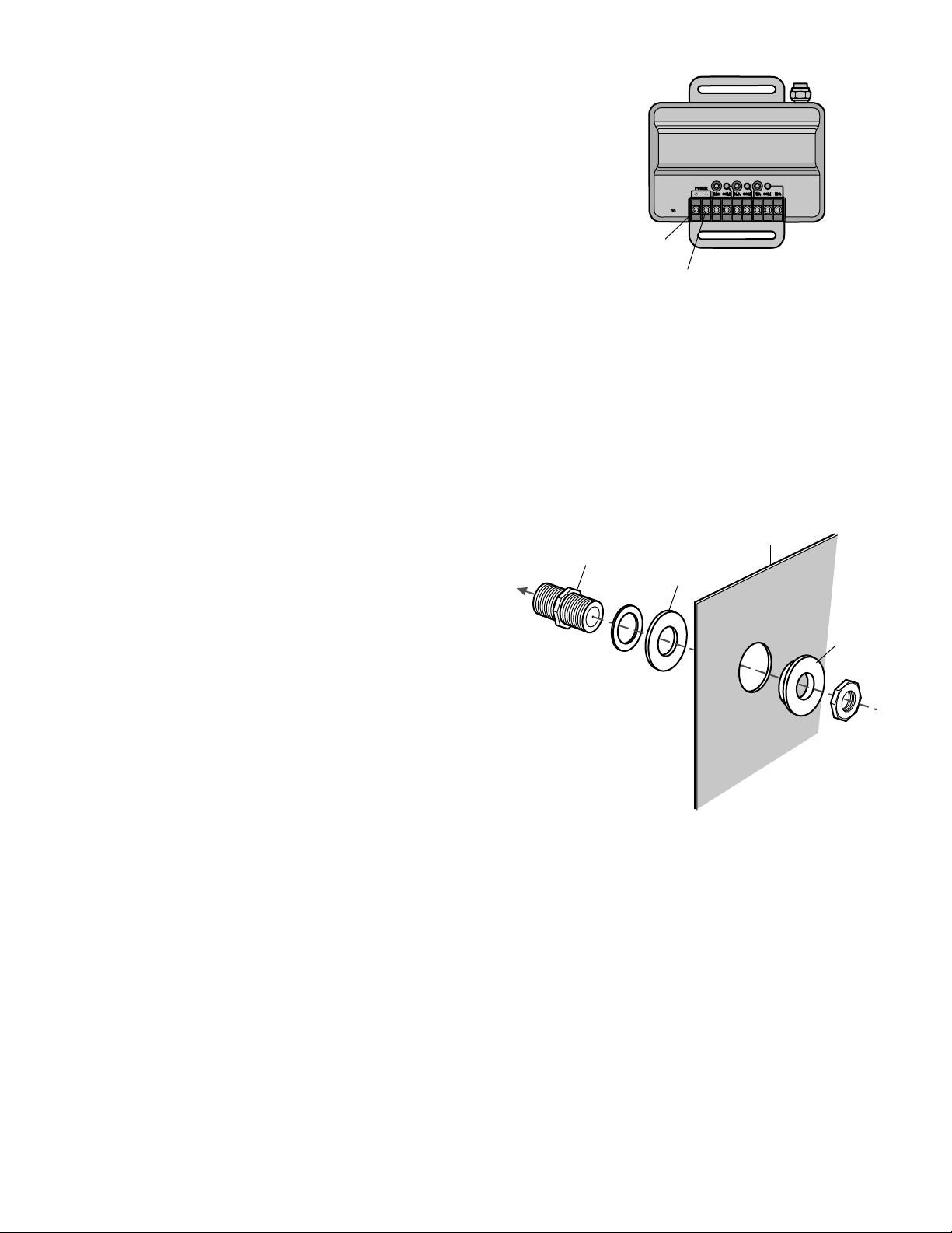
7. Réinstaller le connecteur « F » sur le châssis. Insérer les
rondelles d’isolation entre le châssis de l’actionneur et l’autre
visserie. La rondelle à épaulement doit aller à l’intérieur de
l’actionneur. La rondelle plate doit aller à l’extérieur de
l’actionneur. Voir l’illustration pour l’ordre d’assemblage.
8. Reconnecter les câbles coaxiaux au connecteur « F ».
9. Connecter la masse de l’antenne au châssis.
10. Connecter tous les autres accessoires conformément aux
instructions qui les accompagnent.
11. Restaurer l’alimentation à l’actionneur et tester ce dernier.
Châssis
Rondelle plate
en nylon
Connecteur « F »
Vers l’antenne
Rondelle
à épaulement
en nylon
Entrée
d’alimentation (+)
Entrée
d’alimentation (-)
APLICACIÓN
El juego de aislamiento de antena protege a los componentes del
operador del portón contra la posibilidad de daño que podrían
causar ciertos tipos de conexión. La instalación de ciertos
accesorios exige que una de las salidas del transformador sea
puenteada a la tierra del chasis. Esto podría quemar el fusible del
transformador o dañar el receptor universal. LiftMaster
®
NO
recomienda conectar la salida del transformador a la tierra del
chasis, pero ciertos accesorios de terceros exigen que una de las
salidas del transformador esté puenteada a tierra del chasis.
El juego de aislamiento es apto para los siguientes modelos de
operadores de portón: SL575, SL585, SL595, HS670, SW420,
SW279 y SW490.
CONTENIDO DE LA CAJA
Arandela plana de nailon. . . . . . . . . . . . . . . . . . . . . . . (216A0253)
Arandela de nailon con resalto . . . . . . . . . . . . . . . . . . (184A0182)
Fusible . . . . . . . . . . . . . . . . . . . . . . . . . . . . . . . . . . . (35-310-032)
Fusible . . . . . . . . . . . . . . . . . . . . . . . . . . . . . . . . . (35-310-032-1)
HERRAMIENTAS NECESARIAS
• Pinza y llaves
• Destornilladores
• Alicates
• Pelacables
• Taladro
• Broca de 1/2 de pulg.
• Voltímetro digital
DETERMINAR SI ES NECESARIO USAR EL
JUEGO DE AISLAMIENTO
Para determinar si es necesario usar el juego de aislamiento:
1. Desconectar la alimentación eléctrica del operador.
2. Desconectar del operador el receptor universal (modelo
850LM). El lugar de instalación dependerá del tipo de
operador. Consultar el manual de instrucciones.
3. Conectar los demás accesorios según sus propias
instrucciones.
4. Conectar la alimentación eléctrica del operador.
5. Poner el selector del voltímetro digital para medir voltaje de
corriente alterna. Tomar tres medidas de voltaje entre los
siguientes puntos: R1-R2, R1-tierra de chasis y R2-tierra de
chasis. El lugar de instalación dependerá del tipo de
operador. Consultar el manual de instrucciones.
Si no se midiera voltaje entre R1-R2, verificar que el fusible
del transformador no estuviera quemado. Si el fusible
estuviera quemado, cambiarlo por el fusible del juego y volver
a medir el voltaje.
6. Consultar la tabla y seguir las instrucciones para las
mediciones de voltaje tomadas.
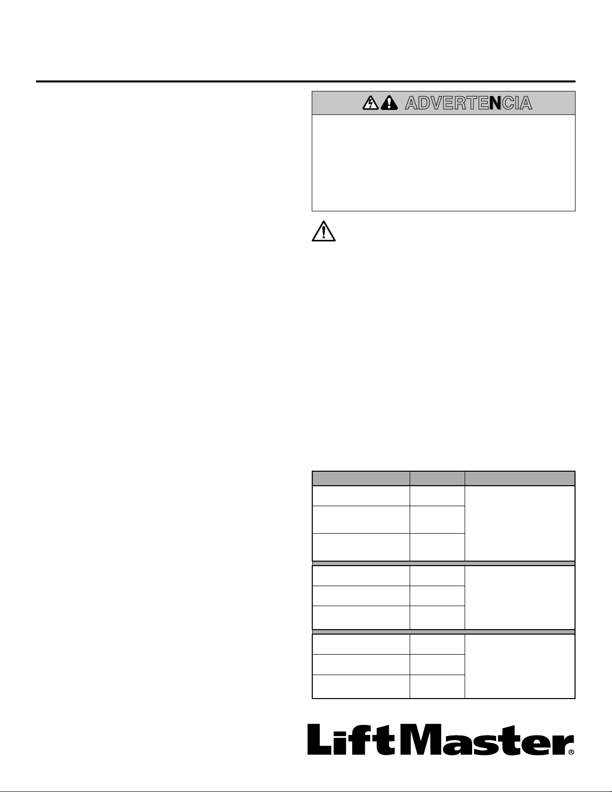
Para reducir el riesgo de LESIONES GRAVES o la MUERTE:
• Desconectar la alimentación eléctrica a la caja de fusibles
ANTES de continuar.
• TODAS las conexiones eléctricas DEBEN ser realizadas por
un técnico capacitado.
• Al finalizar la instalación del juego, limpiar y despejar el
lugar. Entonces la unidad podrá ponerse en servicio.
ADVERTENCIA
PUNTOS DE MEDICIÓN VOLTAJE INSTRUCCIONES
R1-R2 24 VAC Ninguna de las salidas
del transformador está
puenteada a tierra.
El juego de aislamiento
NO es necesario.
R1-tierra de chasis Aprox.
14 VAC
R2-tierra de chasis Aprox.
14 VAC
R1-R2 24 VAC
R1 está puenteado a
tierra.
Vez sección PROBAR EL
RECEPTOR UNIVERSAL
PARA DETECTAR DAÑO.
R1-tierra de chasis 0 VAC
R2-tierra de chasis 24 VAC
R1-R2 24 VAC
R2 está puenteado a
tierra.
Vez sección PROBAR EL
RECEPTOR UNIVERSAL
PARA DETECTAR DAÑO.
R1-tierra de chasis 24 VAC
R2-tierra de chasis 0 VAC
Juego de aislamiento de antena
K001A3200-2
ADVERTENCIA: Este producto puede exponerle
a productos químicos (incluido el plomo), que a
consideración del estado de California causan cáncer,
defectos congénitos u otros daños reproductivos. Para
más información, visite www.P65Warnings.ca.gov

6
PROBAR EL RECEPTOR UNIVERSAL PARA
DETECTAR DAÑO
Podría ser necesario cambiar el receptor universal instalado
(modelo 850LM). Para probar el receptor universal:
1. Desconectar la alimentación eléctrica del operador.
2. Desconectar del operador el receptor universal.
3. Poner el selector del voltímetro digital para medir resistencia.
4. Conectar el negativo (cable negro) del voltímetro al conector
“F” de conexión a tierra de la antena del receptor universal.
5. Conectar el positivo (cable rojo) del voltímetro a:
a. La entrada positiva (+) de alimentación del receptor
universal. Si el multímetro mide 0 Ω, significa que hay un
cortocircuito y el receptor está dañado. Cambiar el
receptor universal.
b. La entrada negativa (-) de alimentación del receptor
universal. Si el multímetro mide 0 Ω, significa que hay un
cortocircuito y el receptor está dañado. Cambiar el
receptor universal.
NOTA: No confundir 0 Ω con ∞ Ω.
6. Si el voltímetro no indicara un cortocircuito puede utilizar el
receptor universal.
INSTALAR EL JUEGO DE AISLAMIENTO
Para instalar el juego de aislamiento:
1. Desconectar la alimentación eléctrica del operador.
2. Desconectar todos los accesorios del operador.
3. Ubicar el conector “F” montado en el chasis (adonde la
antena coaxial pasa por el chasis del operador). El lugar de
instalación dependerá del tipo de operador. Consultar el
manual de instrucciones.
4. Desconectar los cables coaxiales de ambos lados del
conector “F”.
5. Quitar el conector “F” y los accesorios de montaje. Hacerlos a
un lado para volver a instalarlos.
6. Hacer un orificio con una broca de 1/2 de pulg.
7. Volver a instalar el conector “F” en el chasis. Colocar las
arandelas de aislamiento entre el chasis y el resto de los
accesorios de montaje. La arandela con resalto debe quedar
del lado interno del operador. La arandela plana debe quedar
del lado externo del operador. Véase en la ilustración el orden
de montaje.
8. Conectar los cables coaxiales al conector “F”.
9. Conectar la tierra de antena al chasis.
10. Conectar los demás accesorios según sus propias
instrucciones.
11. Conectar la alimentación eléctrica y probar el funcionamiento
del operador.
Chasis
Arandela plana
de nailon
Conector “F”
A la antena
Arandela
de nailon
con resalto
Entrada de
alimentación (+)
Entrada de
alimentación (-)

7

©2015 LiftMaster
All Rights Reserved
Tous droits réservés
01-37828B Todos los derechos reservados