Loading ...
Loading ...
Loading ...
STEP 4 (cont.)
Weatherproofing
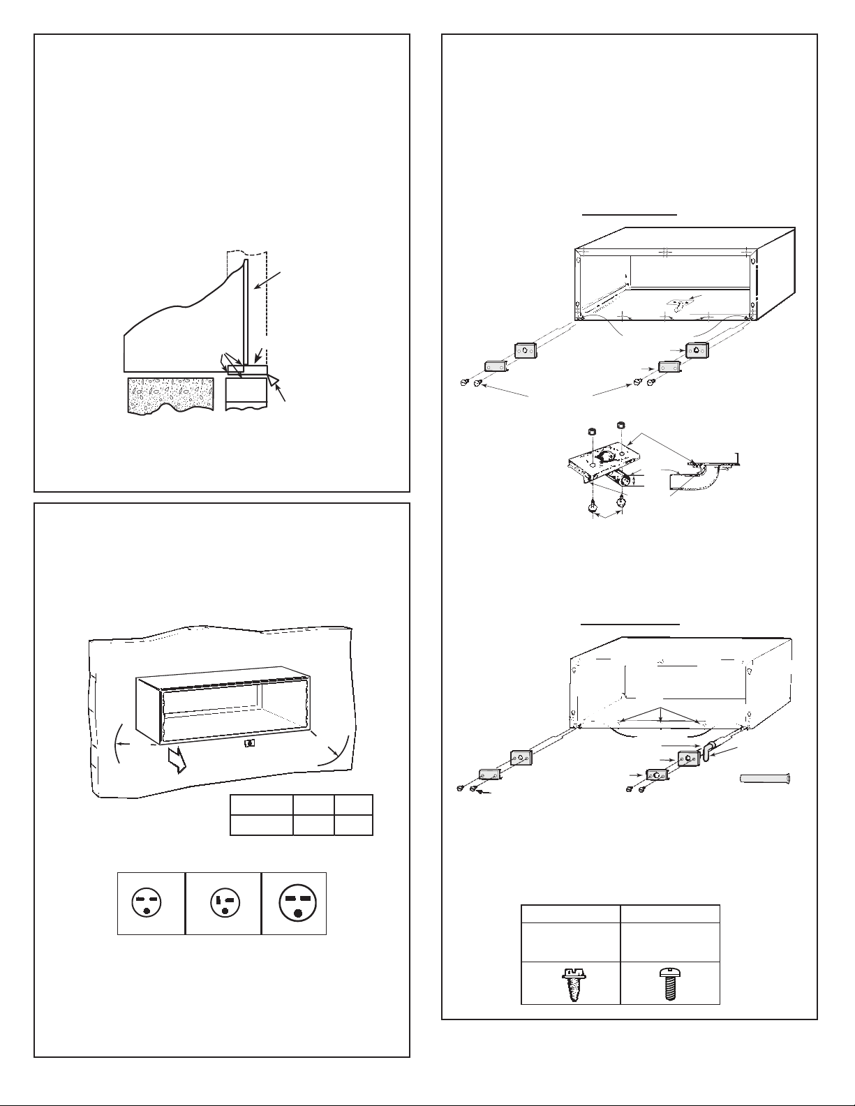
For installation in extra
thick walls
1. If the sleeve is being installed in a thick wall, where
2.
NOTE:
* It is critical to caulk around perimeter of
wall sleeve on all four sides where it joins the
building to prevent air and water infiltration.
3
Outdoor
grille
Drip rail
Sleeve
Caulk*
Flashing
the sleeve is recessed more than 3”, a sleeve
extension with splitters aligned with the chassis
condenser end sheets must be used.
If the sleeve is being installed in a wall where the
recess is 3” or less, and an extended wall sleeve is
not used, flashing must be installed under the
sleeve and extend up 2” on each side. The flashing
must include a drip rail as illustrated in the figure
below.
ELECTRICAL REQUIREMENTS
Wall Receptacles
Inside
“A”
“B”
230V/208V 15 amp 230V/208V 20 amp 230V 30 amp
“tandem” type “perpendicular” type “tandem” type
All wiring should be made in accordance with local
electrical codes and regulations.
See the Owner’s Manual for how to connect electrical
supply.
NOTE:
Aluminum wiring in a structure may pose special
problems - consult a qualified electrician.
Provisions should be made to have the proper
electrical outlet near the sleeve. All wiring should be
made in accordance with local codes and regulations.
The line cord included with the chassis (if used) will
extend to a wall receptacle located within the area
shown in tabulation below.
Model
AZ Series
“A” “B”
21”
58”
DRAIN KIT
If it is necessary to install a drain kit on this wall sleeve,
the following kit is available:
RAD10 Internal/External Drain
NOTE:
It may be desirable or necessary to install the drain kit
on the sleeve prior to installing the sleeve into
the wall.
SCREW
Hex Head
EXTERNAL
DRAIN
Square drain holes
Neoprene foam gasket
Steel mounting plate
Hex head screws
½” O.D. drain tube
Alternate
3” long, ½”
O.D. straight
copper tube.
Overflow relief drains
WALL SLEEVE WITH RAD10 DRAIN UNIT
EXTERNAL DRAIN
SCREW
Pan Head
INTERNAL
DRAIN
See detail
below
Overflow relief drain
Square drain holes
Neoprene foam gasket
Steel mounting plate
Hex head screws
Gasket
Cabinet bottom
Tube
Cover plate
Pan Head screws
½” O.D.
Note: Shaded parts
included with
RAD10 drain kit
WALL SLEEVE WITH RAD10 DRAIN UNIT
INTERNAL DRAIN
1. With an “Internal Drain”, the condensate drain tube
must be connected to an internal drain system
in the building.
2. With an “External Drain” (which may be connected
to a field supplied drain line), condensate water
can be drained away from the unit and building.
Note: Shaded parts
included with
RAD10 drain kit
Nuts