Loading ...
Loading ...
Loading ...
44 lbf·ft (59 N·m , 6.0 kgf·m)
23 lbf·ft (31 N·m , 3.2 kgf·m)
23 lbf·ft (31 N·m , 3.2 kgf·m)
16 lbf·ft (22 N·m , 2.2 kgf·m)
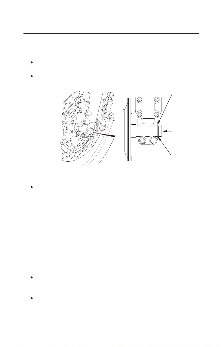
index line
front axle
shaft
recessed surface
223
Taking Care of the Unexpected
If You Have a Flat Tire
Installation
Reassemble the removed parts in the reverse order of removal.
Position the wheel between the fork legs and insert the front axle shaft
from the left side, through the left fork leg and wheel hub.
Fit the brake disc carefully between the brake pads to avoid damaging the
pads.
Align the index line of the front axle shaft with the recessed surface of the
fork leg.
Measure the clearance between the brake disc and the caliper holder on each
side with a 0.028 in (0.7 mm) feeler gauge.
If the feeler gauge inserts easily, remove it and tighten the axle pinch bolts
to the specified torque:
If the feeler gauge cannot be inserted easily, loosen the left axle pinch bolt
and pull the left fork outward or push inward to adjust the clearance. Then
tighten the axle pinch bolts to the specified torque.
Install the bolts and tighten to the specified torque:
axle bolt:
right caliper fixing bolts:
left caliper socket bolt:
(cont’d)
1.
2.
3.
08/11/21 11:03:34 31MCA690 0230
Loading ...
Loading ...
Loading ...