MWOTR30102SS
EN
|
FR
TINSKB303MRR0
Over The Range
Microwave Oven
Installation Manual
TINSKB303MRR0_MWOTR30102SS_Beko OTR_Install Manual.indd 1TINSKB303MRR0_MWOTR30102SS_Beko OTR_Install Manual.indd 1 8/19/20 2:41 PM8/19/20 2:41 PM
2 / 29 EN Over The Range Microwave Oven / Installation Manual
CONTENTS
1 MOUNTING SPACE ............................. 3
2 WALL CONSTRUCTION .....................4
3 ELECTRICAL GROUNDING
INSTRUCTIONS ..................................5
4 HOOD EXHAUST DUCT .....................6
Exhaust connection ................................................6
Rear exhaust ..........................................................6
Maximum duct length .............................................6
5 TOOLS RECOMMENDED FOR
INSTALLATION ...................................7
6 INSTALLATION HARDWARE .............8
7 VENTILATION SYSTEM ......................9
A. Recirculating: Non-vented, ductless operation ..9
B. Horizontal ventilation system .............................9
C. Vertical ventilation system ...............................11
8 OVEN INSTALLATION ......................12
Mounting plate ...................................................... 12
9 MOUNTING OVEN TO THE WALL ...13
Preparation of top cabinet ....................................13
10 CONNECTING DUCTWORK ............. 14
11 CHECK LIST FOR OPERATION .......15
TINSKB303MRR0_MWOTR30102SS_Beko OTR_Install Manual.indd 2TINSKB303MRR0_MWOTR30102SS_Beko OTR_Install Manual.indd 2 8/19/20 2:41 PM8/19/20 2:41 PM
Please read all instructions thoroughly before
installing the Over The Range Microwave Oven.
Two people are recommended to install this
product.
If a new electrical outlet is required this must be
completed by a qualified electrician before the
Over-the-range microwave oven is installed. See
ELECTRICAL GROUNDING INSTRUCTIONS.
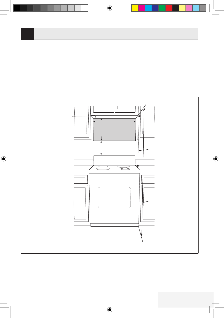
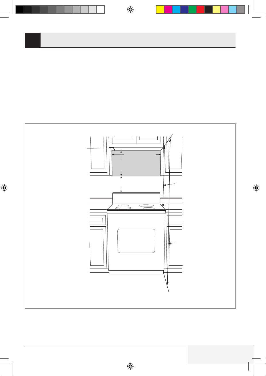
This oven requires a mounting space on a wall as
shown in Figure 1.
For proper installation and servicing, a 2 in/
51 mm space is necessary between the top of
the range backsplash and the bottom of the oven.
3 / 29 ENOver The Range Microwave Oven / Installation Manual
MOUNTING SPACE1
Backsplash
Min. 30"
(762 mm)
At least 2" (50.8 mm)
16
5
/16"
(414 mm)
66" (1676.4 mm)
or more from floor
30" (762 mm)
or more from
cookingsurface
Min. 12" (304.8 mm)
Max. 13" (330.2 mm)
Figure 1
TINSKB303MRR0_MWOTR30102SS_Beko OTR_Install Manual.indd 3TINSKB303MRR0_MWOTR30102SS_Beko OTR_Install Manual.indd 3 8/19/20 2:41 PM8/19/20 2:41 PM
4 / 29 EN Over The Range Microwave Oven / Installation Manual
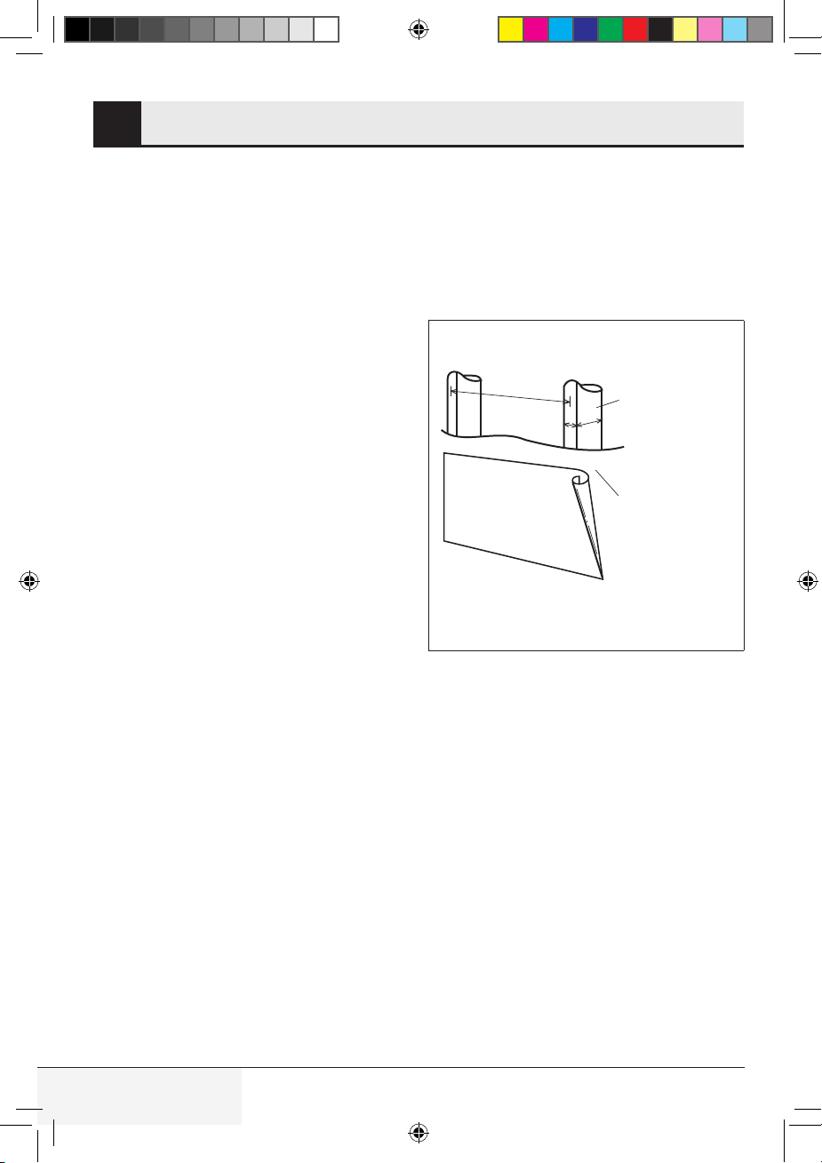
WALL CONSTRUCTION2
This Over-the-range microwave oven should be
mounted against and supported by a flat vertical
wall. The wall must be flat for proper installation.
If the wall is not flat, use spacers to fill in the gaps.
Wall construction should be a minimum of 2 in x
4 in (51 mm x 102 mm) wood studding and
3
⁄8 in
(10 mm) or more thick dry wall or plaster/lath. The
mounting surfaces must be capable of supporting
weight of 110 lb (50 kg)—the oven and contents
and the weight of all items which would normally
be stored in the top cabinet above the unit.
The unit should be attached to a minimum of one
2 in x 4 in (51 mm x 102 mm) wall stud.
To find the location of the studs, one of the follow-
ing methods may be used:
A. Use a stud finder, a magnetic device which
locates the nails in the stud.
B. Use a hammer to tap lightly across the
mounting surface to find a solid sound. This
will indicate stud location.
The center of the stud can be located by probing
the wall with a small nail to find the edges of the
stud and then placing a mark halfway between
the edges. The center of any adjacent studs will
normally be 16 in (406.4 mm) or 24 in (610 mm)
to either side of this mark.
If the unit is unable to be supported by a stud,
toggle bolts and top cabinet screws will need to
be placed, see details in the WALL TEMPLATE.
The top cabinet should be tested to ensure it is
securely attached to the wall. Place extra weight
up to 110 lb (50 kg) inside the top cabinet to test
the support.
2"x 4"
(51 mm x 102 mm)
wood studs
3/8" (10 mm)
dry wall or
plaster/lath
16" (381 mm) or 24" (9610 mm)
Figure 2
TINSKB303MRR0_MWOTR30102SS_Beko OTR_Install Manual.indd 4TINSKB303MRR0_MWOTR30102SS_Beko OTR_Install Manual.indd 4 8/19/20 2:41 PM8/19/20 2:41 PM
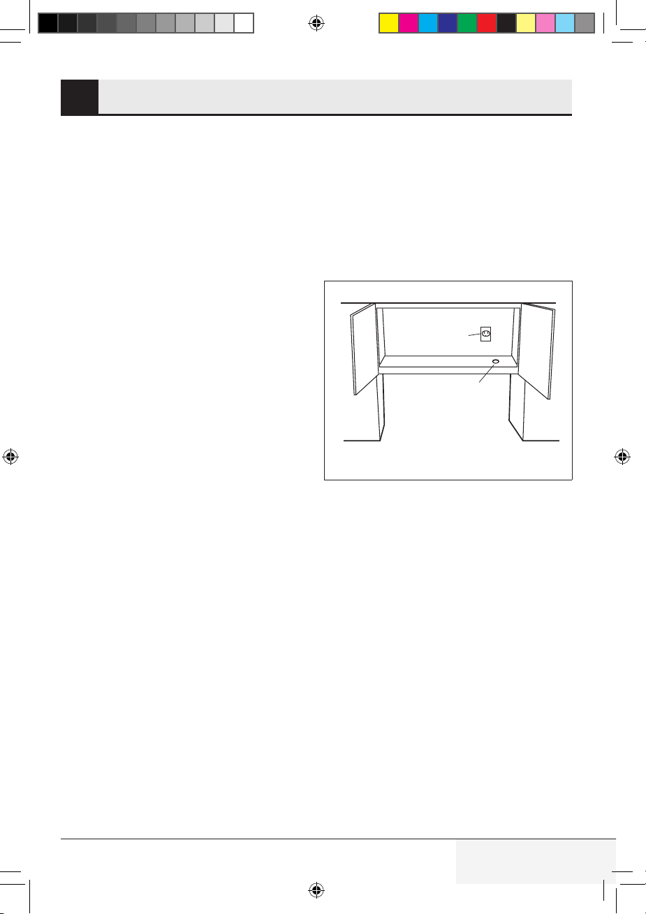
This appliance must be grounded. This oven is
equipped with a cord having a grounding wire with
a grounding plug. It must be plugged into a wall
receptacle that is properly installed and grounded
in accordance with the National Electrical Code
and local codes and ordinances. In the event of
an electrical short circuit, grounding reduces risk
of electric shock by providing an escape wire for
the electric current.
WARNING - Improper use of the grounding plug
can result in a risk of electric shock.
The oven is equipped with a 3-prong grounding
plug. DO NOT UNDER ANY CIRCUMSTANC-
ES CUT OR REMOVE THE GROUNDING PIN
FROM THE PLUG.
The Power Supply Cord and plug must be
connected to a dedicated 120 Volt AC, 60 Hz,
15 Amp, or branch circuit, single grounded
receptacle. The receptacle should be located
inside the cabinet directly above the Over the
range microwave oven mounting location.
NOTE:
1. If you have any questions about the grounding
or electrical instructions, consult a qualified
electrician or serviceperson.
2. No liability can be accepted for damage to the
oven or personal injury resulting from failure to
observe the correct electrical connection pro-
cedures.
Ground
Receptacle
Opening for
Power Cord
Figure 3
5 / 29 ENOver The Range Microwave Oven / Installation Manual
ELECTRICAL GROUNDING INSTRUCTIONS3
TINSKB303MRR0_MWOTR30102SS_Beko OTR_Install Manual.indd 5TINSKB303MRR0_MWOTR30102SS_Beko OTR_Install Manual.indd 5 8/19/20 2:41 PM8/19/20 2:41 PM
6 / 29 EN Over The Range Microwave Oven / Installation Manual
HOOD EXHAUST DUCT4
When the hood is vented to the outside, a hood
exhaust duct is required. All ductwork must be
metal; do not use plastic duct. Check that all con-
nections are secure. Please read the following
carefully:
Exhaust connection
The hood exhaust has been designed to connect
to a standard 3
1
⁄4 in x 10 in (82.5 mm x 254 mm)
rectangular duct. If round duct is required, a rect-
angular-to-round adapter must be used.
Rear exhaust
If a rear or horizontal exhaust is to be used,
care should be taken to align the exhaust with
the space between the studs, or wall should be
prepared at the time it is constructed by leaving
enough space between wall studs to accommo-
date the exhaust.
Maximum duct length
For satisfactory air movement, the total duct
length of 3
1
⁄4 in x 10 in (82.5 mm x 254 mm)
rectangular or 6 in (152 mm) diameter round duct
should not exceed 140 feet (42.67 meters).
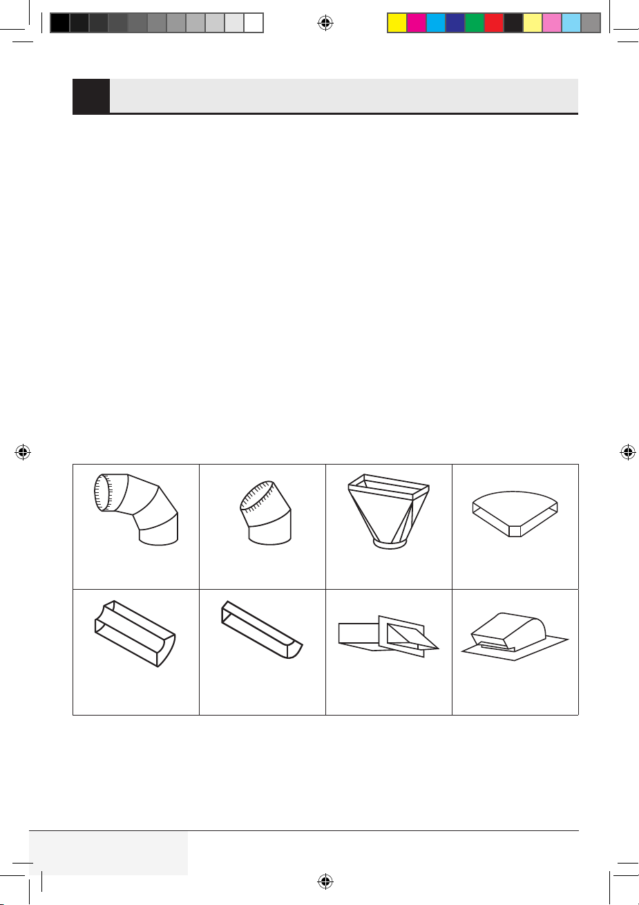
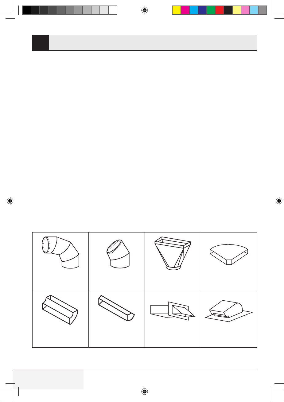
Elbows, adapters, wall and roof caps present ad-
ditional resistance to air flow and are equivalent
to a section of straight duct which is longer than
their actual physical size. When calculating the
total length, add the equivalent lengths of all tran-
sitions and adapters plus the length of all straight
duct sections. Figure 4 shows the approximate
feet of equivalent length of some typical ductwork
parts.
Use the values in parentheses for calculating air
flow resistance equivalent, which should total
less than 140 feet (42.67 meters).
90˚ Elbow
(10 ft. / 304.8 cm.)
45˚ Elbow
(5 ft. / 152.4 cm.)
Adaptor
(5 ft. / 152.4 cm.)
10˚ Wide elbow
(10 ft. / 304.8 cm.)
90˚ Elbow
(25 ft. / 762 cm.)
45˚ Elbow
(5 ft. / 152.4 cm.)
Wall cap
(40 ft. / 1219.2 cm.)
Roof cap
(24 ft. / 731.52 cm.)
Figure 4
TINSKB303MRR0_MWOTR30102SS_Beko OTR_Install Manual.indd 6TINSKB303MRR0_MWOTR30102SS_Beko OTR_Install Manual.indd 6 8/19/20 2:41 PM8/19/20 2:41 PM

7 / 29 ENOver The Range Microwave Oven / Installation Manual
TOOLS RECOMMENDED FOR INSTALLATION5
• Phillips screwdriver
• Electric drill
• 1
1
⁄2 in (38 mm) wood bit or metal hole cutter (if metal cabinet is used)
•
1
⁄2 in (12.7 mm),
5
⁄8 in (15.8 mm) and
3
⁄32 in (2.3 mm) drill bits
• Scissors
• Pencil
• Tape
• Measure tape
• Saw to cut exhaust opening (if needed)
• Protective drop cloth for product and range—you may also use carton for protection
TINSKB303MRR0_MWOTR30102SS_Beko OTR_Install Manual.indd 7TINSKB303MRR0_MWOTR30102SS_Beko OTR_Install Manual.indd 7 8/19/20 2:41 PM8/19/20 2:41 PM
8 / 29 EN Over The Range Microwave Oven / Installation Manual
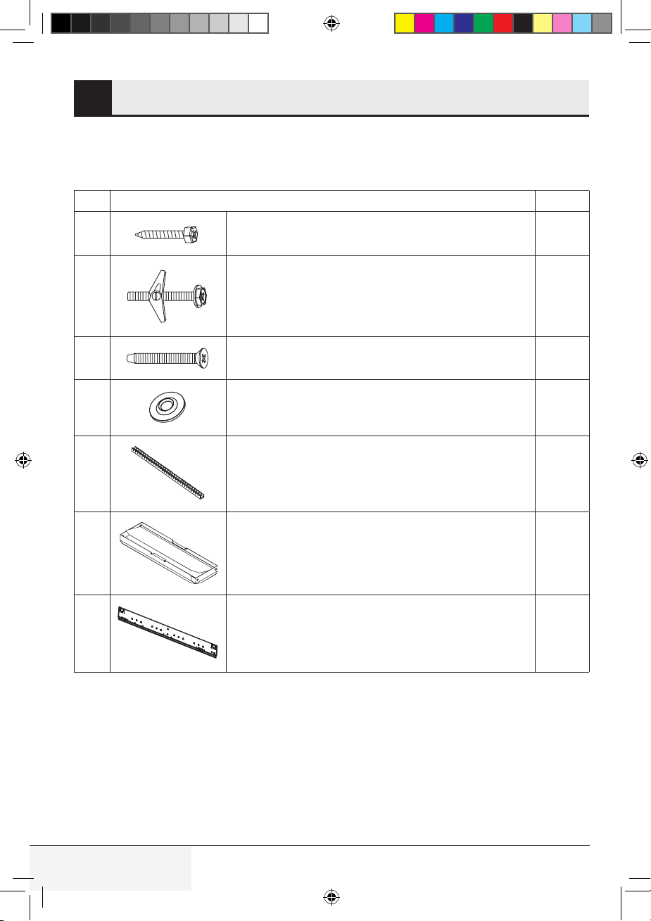
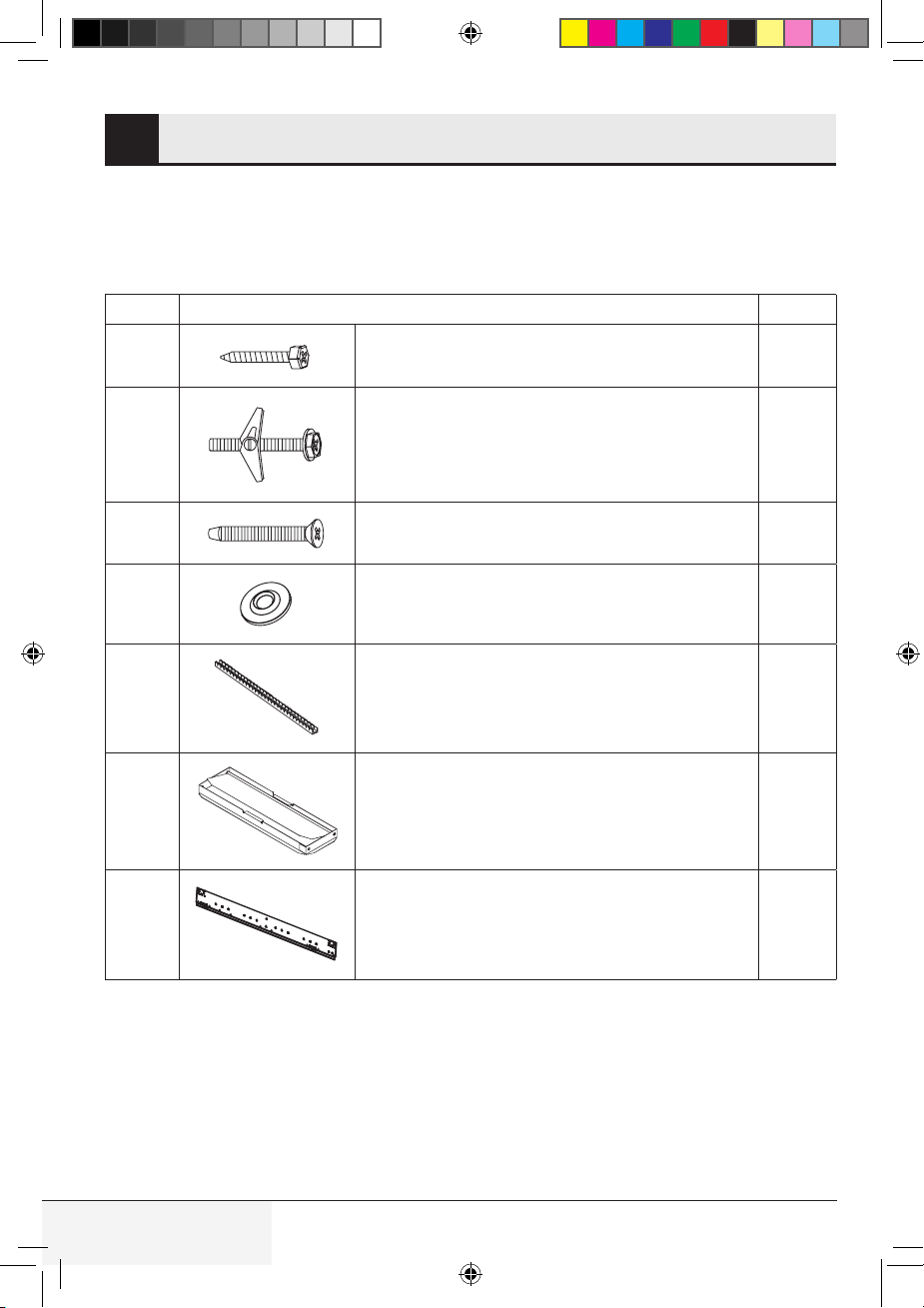
INSTALLATION HARDWARE6
The following is a list of parts you may need for installing your Over-the-range microwave oven. You
will find the installation hardware contained in a packet with the unit. Check to make sure you have all
these parts.
Item Part Quantity
1
1
Lag screws -
1
⁄4" x 1
13
⁄16" (6.3 mm x 45.7 mm) 2
2
Toggle bolts and nuts -
3
⁄16" x 2
11
⁄16" (4.7 mm x 68.6 mm) 2
3
Cabinet mounting bolts -
1
⁄4" x 3
1
⁄8" (6.3 mm x 79 mm) 2
4
4
Washer -
3
⁄4" (19 mm) 2
5
Nylon grommet (for metal cabinets) 1
6
6
Damper 1
7
7
Mounting plate 1
Figure 5
TINSKB303MRR0_MWOTR30102SS_Beko OTR_Install Manual.indd 8TINSKB303MRR0_MWOTR30102SS_Beko OTR_Install Manual.indd 8 8/19/20 2:41 PM8/19/20 2:41 PM
9 / 29 ENOver The Range Microwave Oven / Installation Manual
VENTILATION SYSTEM7
This Over-the-range microwave oven is designed
for adaptation to three types of hood ventilation
systems. Select the type required for your instal-
lation.
A. Recirculating: Non-vented,
ductless operation
The unit is shipped assembled for recirculating.
NOTE:
1. The exhaust damper assembly is not required
for recirculating operation.
2. The charcoal filter should be replaced every 6
months, depending on use.
3. The charcoal filter is also sold as an accessory.
See User Manual for ordering information.
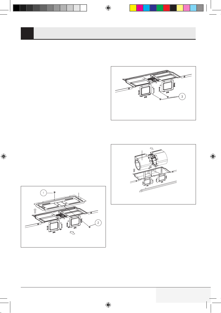
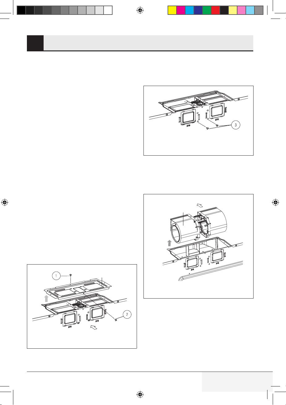
B. Horizontal ventilation
system
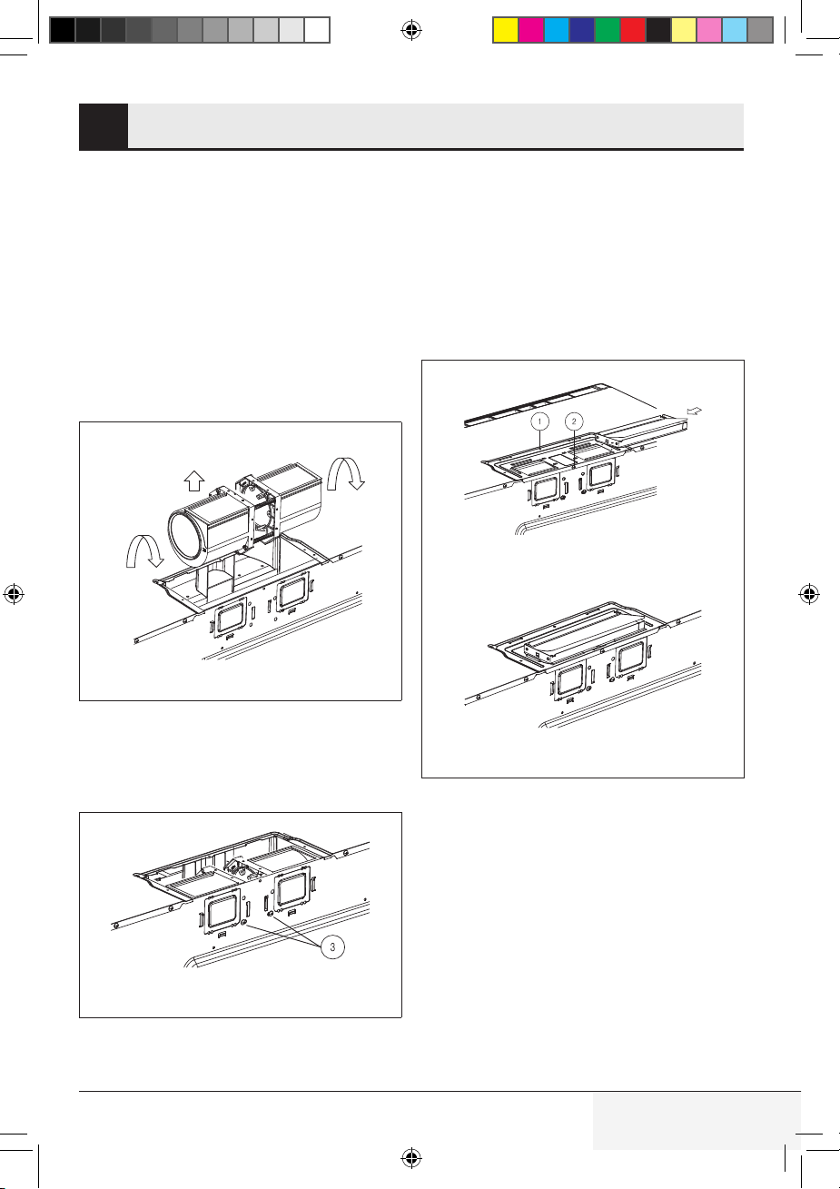
Step 1
• Remove the screws (1) and (2) for opening the
blower motor cover and save screws. Remove
cover. See Figure 6.
Blower motor cover
Back of oven
Figure 6
Step 2
• Remove the screws (3) for blower attachment
and save screws. See Figure 7.
Before : Fan blade openings facing front
Figure 7
• Lift blower unit out of mounting location. See
Figure 8.
CAUTION: Do not pull or stretch blower wiring.
Blower motor
Figure 8
TINSKB303MRR0_MWOTR30102SS_Beko OTR_Install Manual.indd 9TINSKB303MRR0_MWOTR30102SS_Beko OTR_Install Manual.indd 9 8/19/20 2:41 PM8/19/20 2:41 PM
10 / 29 EN Over The Range Microwave Oven / Installation Manual
VENTILATION SYSTEM7
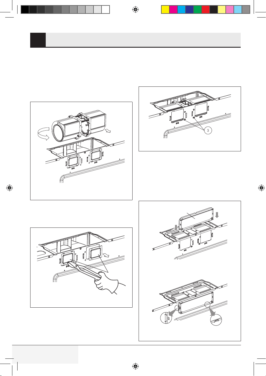
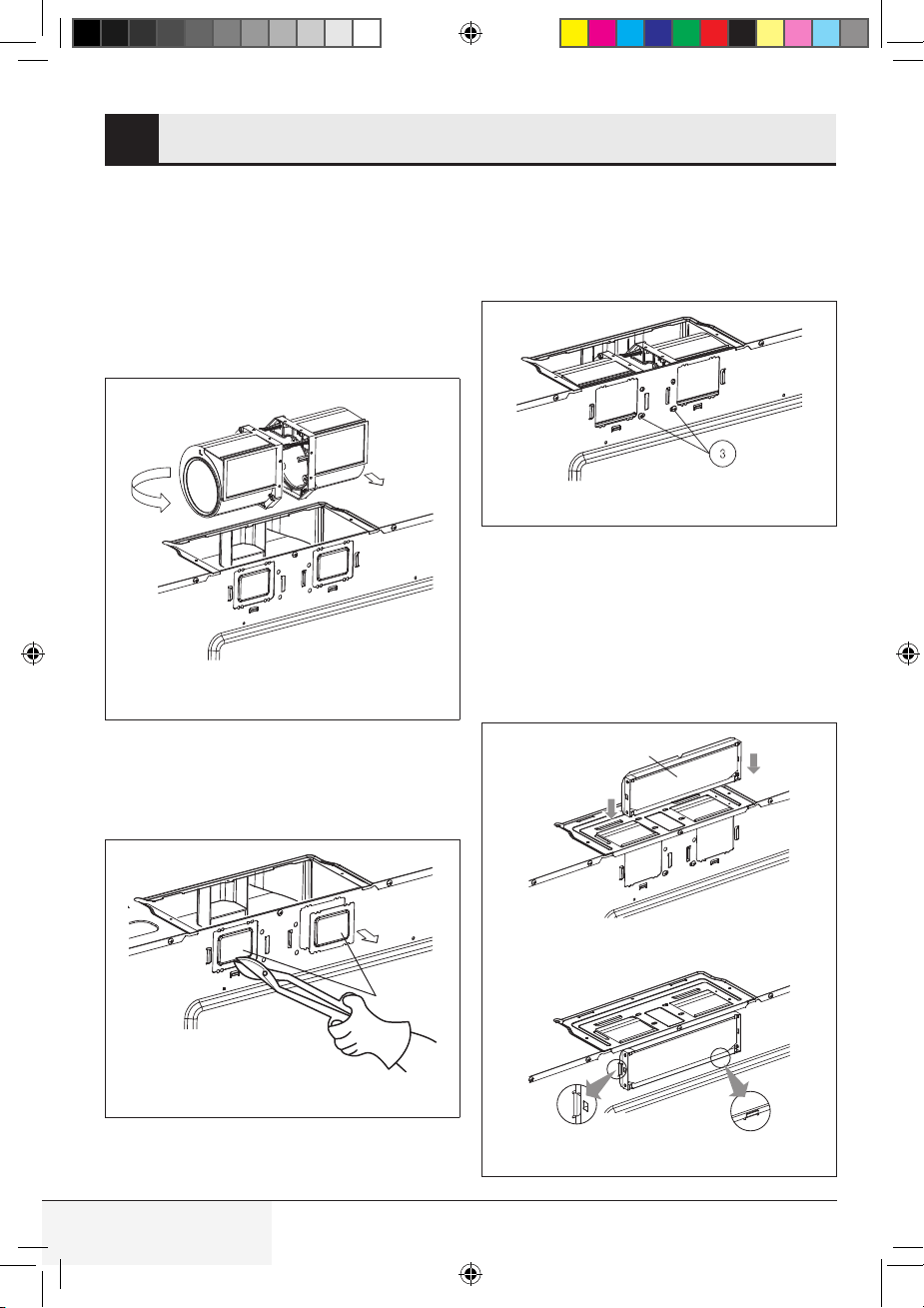
Step 3
• Turn the blower unit so that the fan blade open-
ings are facing back (rear of unit). See Figure 9.
CAUTION: Wires to blower unit must be routed
properly to avoid pinching wires before reinstalla-
tion of cover plate.
After : Fan blade openings facing rear
Turn the blower motor clockwise 180˚
Figure 9
• Use side cutters or tin snips to cut and remove
parts B from back plate. Be careful not to distort
the plate. See Figure 10.
Parts B
Figure 10
Step 4
• Place the blower unit into the opening and
secure it to the oven with the screws (3) from
step 2. See Figure 11.
Figure 11
• Carefully match the exhaust opening location of
the microwave and attach the damper to the rear
plate by sliding it into the guides at the rear plate.
See Figures 12, 13.
• Ensure that the damper hinge is on the top and
the damper swings freely into the wall outlet.
Damper
Figure 12
Figure 13
TINSKB303MRR0_MWOTR30102SS_Beko OTR_Install Manual.indd 10TINSKB303MRR0_MWOTR30102SS_Beko OTR_Install Manual.indd 10 8/19/20 2:41 PM8/19/20 2:41 PM
11 / 29 ENOver The Range Microwave Oven / Installation Manual
VENTILATION SYSTEM7
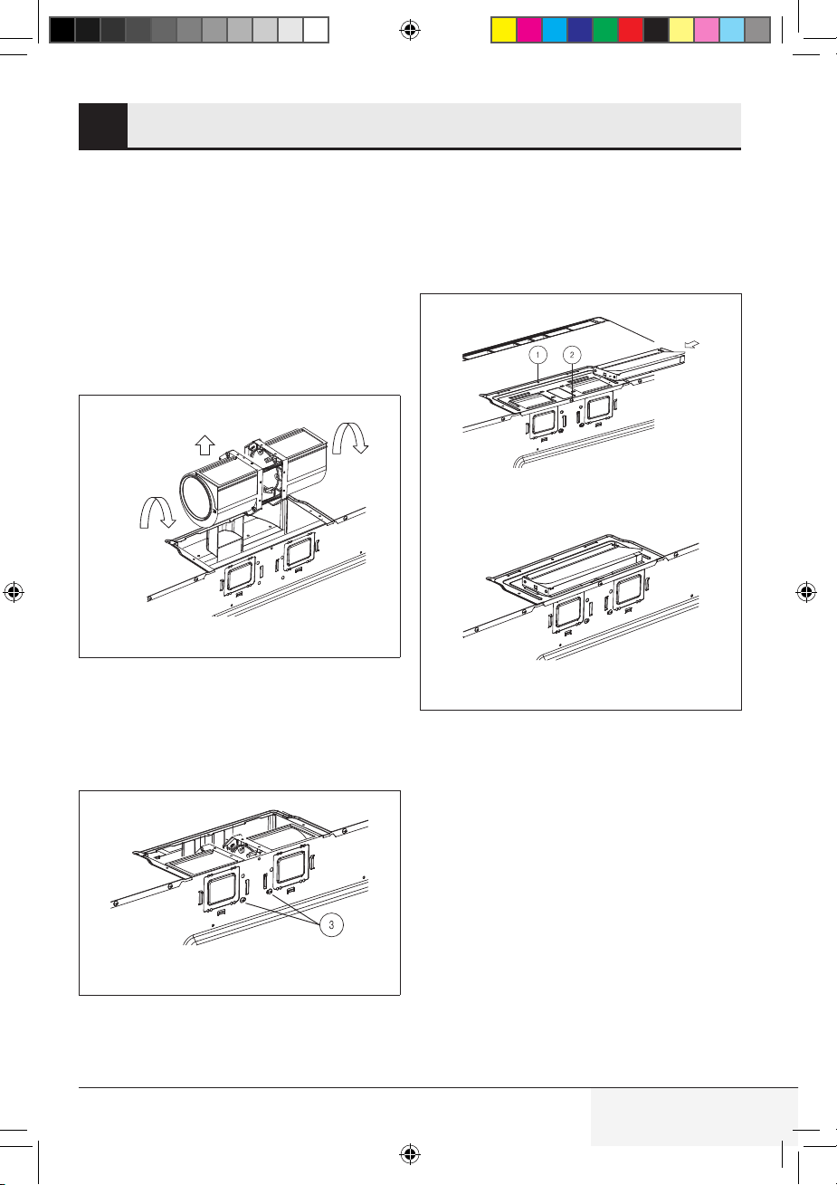
C. Vertical ventilation system
Step 1 & 2
A-1 Ventilation motor. See Section B, steps 1
and 2 for access to the blower motor. Also see
Figure 8.
Step 3
• Turn the blower unit so that the fan blade open-
ings are facing upward. See Figure 14.
Fan blade openings facing up
After turning
Back of oven
Figure 14
Step 4
• Place the blower unit into the opening. Secure
the case blow fan top, the blower motor and
cover to the microwave oven with the screw (1,
2 and 3) from steps 1 and 2. See Figure 15.
Figure 15
• Carefully match the exhaust opening location
of the microwave and attach the damper to
blower motor cover by sliding it into the guides
at the blower motor cover. See Figures 16, 17.
• Ensure that the damper hinge is on the front
and the damper swings free into the wall outlet.
Figure 16
Figure 17
TINSKB303MRR0_MWOTR30102SS_Beko OTR_Install Manual.indd 11TINSKB303MRR0_MWOTR30102SS_Beko OTR_Install Manual.indd 11 8/19/20 2:41 PM8/19/20 2:41 PM
12 / 29 EN Over The Range Microwave Oven / Installation Manual
OVEN INSTALLATION8
This oven cannot be properly installed without re-
ferring to the mounting instructions found on both
templates.
Read and follow mounting information on both
top cabinet template and wall template.
Mounting plate
Step 1- Setup position
• Draw a line down the middle of the studs. See
the Wall Construction, page 4.
• Draw a vertical line on the wall at the center of
the 30 in wide space. See Figure 18.
NOTE: use the wall template for the rear wall.
Reference wall template prior to proceeding. In-
stallation of this product requires 2 people.
A
C
C
B
C
C
Power Supply Cord Hole
House Duct
Mounting Plate
Figure 18
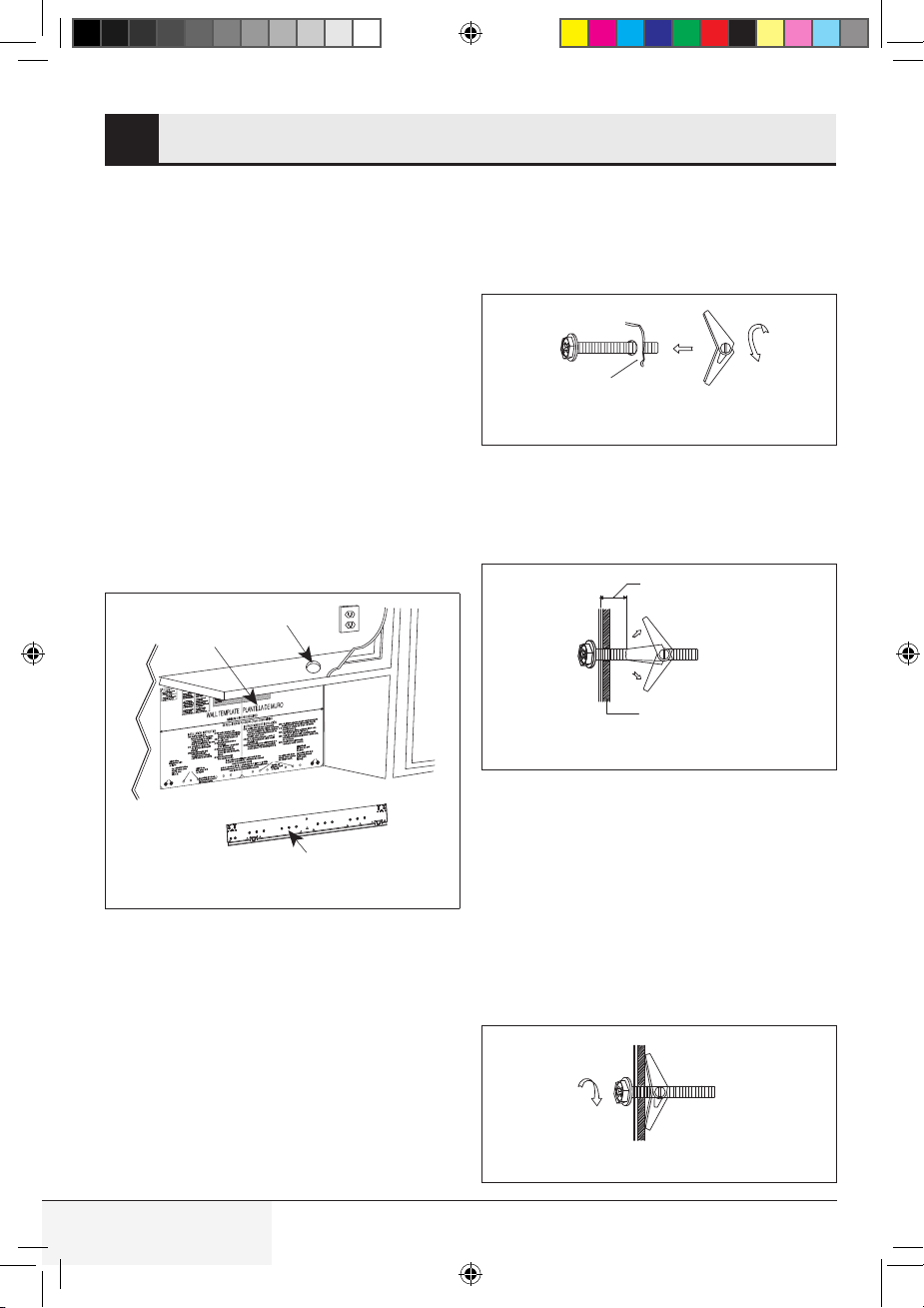
Step 2 - Drilling
• Reference the wall template.
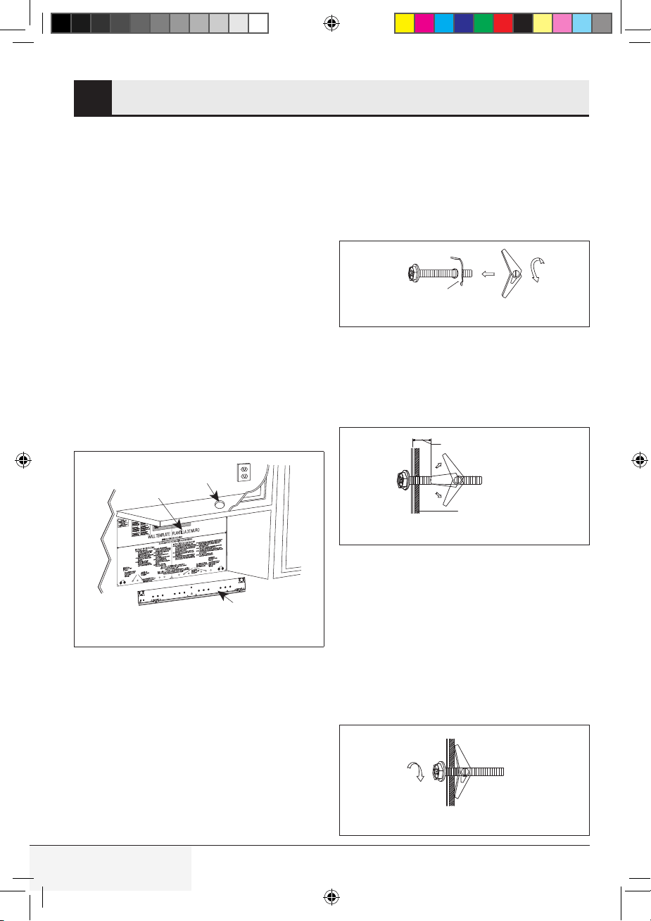
Step 3 - Tightening the screws
To attach the mounting plate to the wall using the
toggle bolt assemblies and/or lag screws:
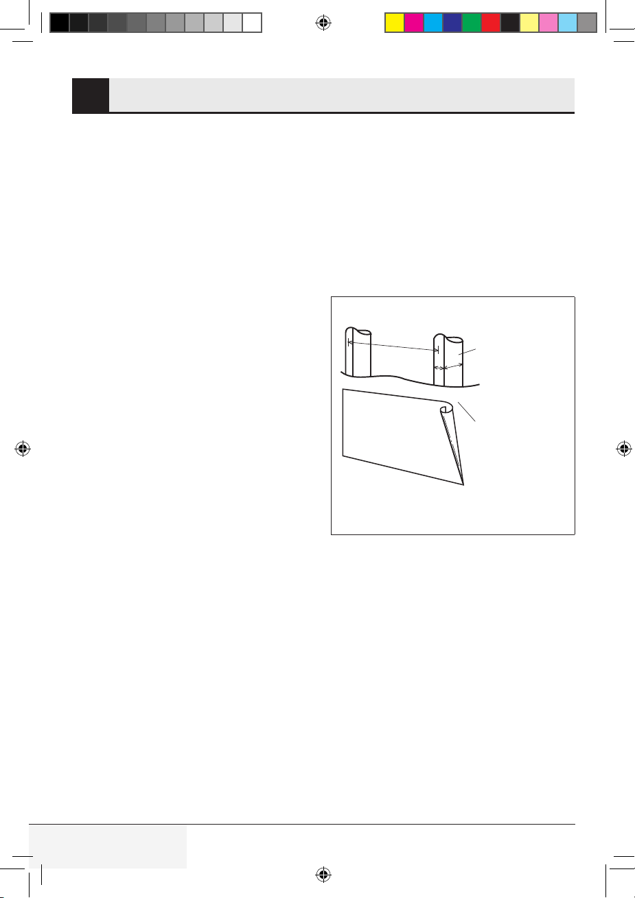
• Insert toggle bolts through the mounting plate
at required locations and add the spring loaded
toggles. See Figure 19.
Ensure you leave space at least the thickness
of the wall between the mounting plate and the
end of the toggle nut, (in closed position). If you
do not leave this space, the toggle nut will not
open on the other side of the wall.
Mounting plate
Figure 19
• Position mounting plate on wall and insert tog-
gle bolt assemblies through the drywall holes or
start the lag-screw(s) through the wall stud(s).
See Figure 20.
Dry Wall
Space more than
wall thickness
Figure 20
• Secure the mounting plate to the wall by
tightening the toggle bolt assemblies or lag
screw(s). See Figure 21.
• Drill
3
⁄16 in (4.7 mm) diameter lag screw hole(s),
into one or more wall studs.
You must have at least one lag screw into a
wall stud. For stud location refer to Wall Con-
struction.
• Tighten the lag screw(s) into wall stud(s).
Figure 21
TINSKB303MRR0_MWOTR30102SS_Beko OTR_Install Manual.indd 12TINSKB303MRR0_MWOTR30102SS_Beko OTR_Install Manual.indd 12 8/19/20 2:41 PM8/19/20 2:41 PM
13 / 29 ENOver The Range Microwave Oven / Installation Manual
MOUNTING OVEN TO THE WALL9
IMPORTANT: Do not grip or use handle during
installation.
Preparation of top cabinet
You need to drill holes for the top support screws
and a hole large enough for the power cord to fit
through.
• Read the instructions on the top cabinet tem-
plate
• Tape it underneath the top cabinet
• Drill the holes, following the instructions on the
template.
NOTE: the top cabinet template must be taped to
the underside of the top cabinet before proceed-
ing with installation.
Step 1
• Protect the top of your range by placing a por-
tion of the carton or some other heavy material
over the cooking surface before mounting your
oven.
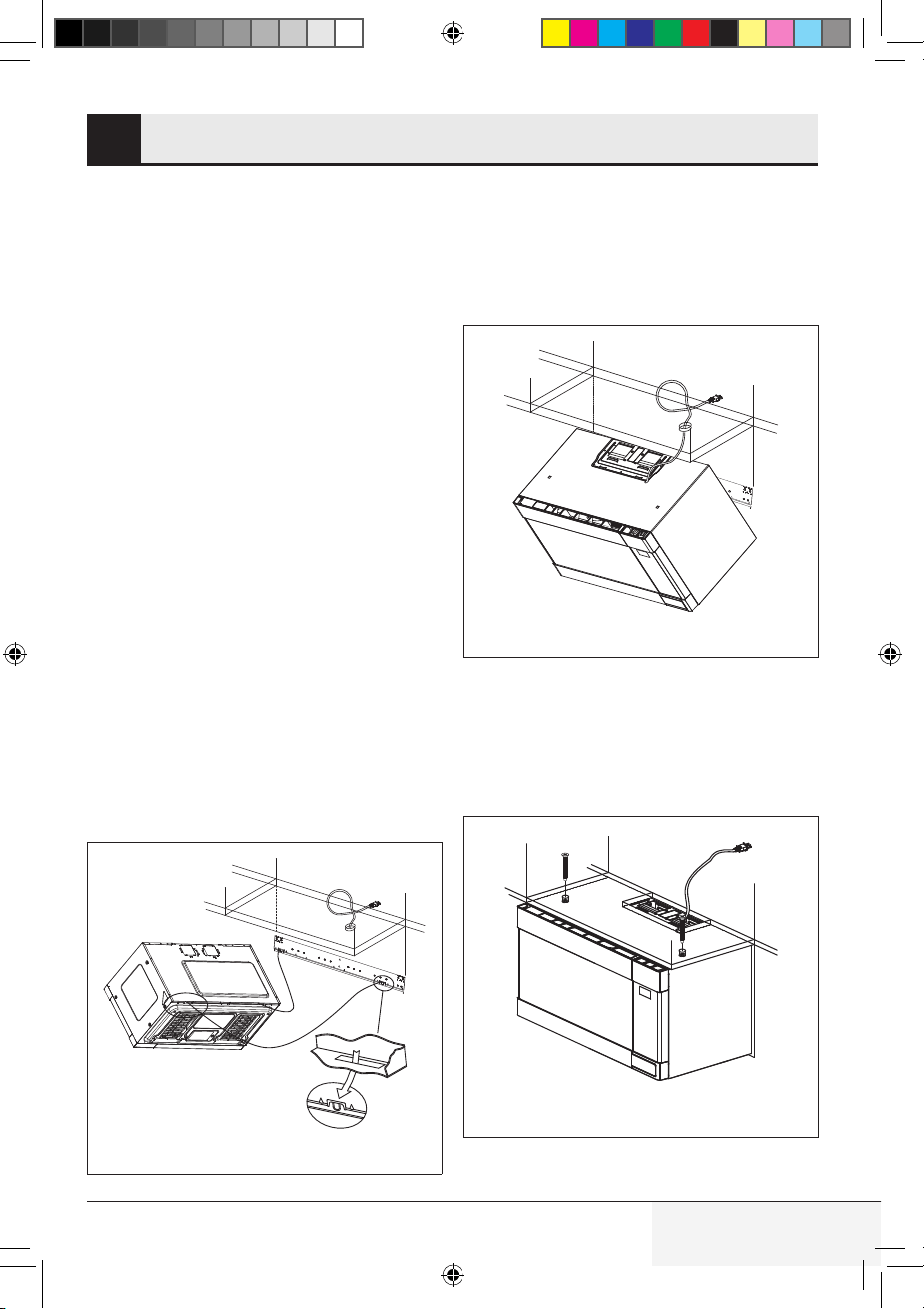
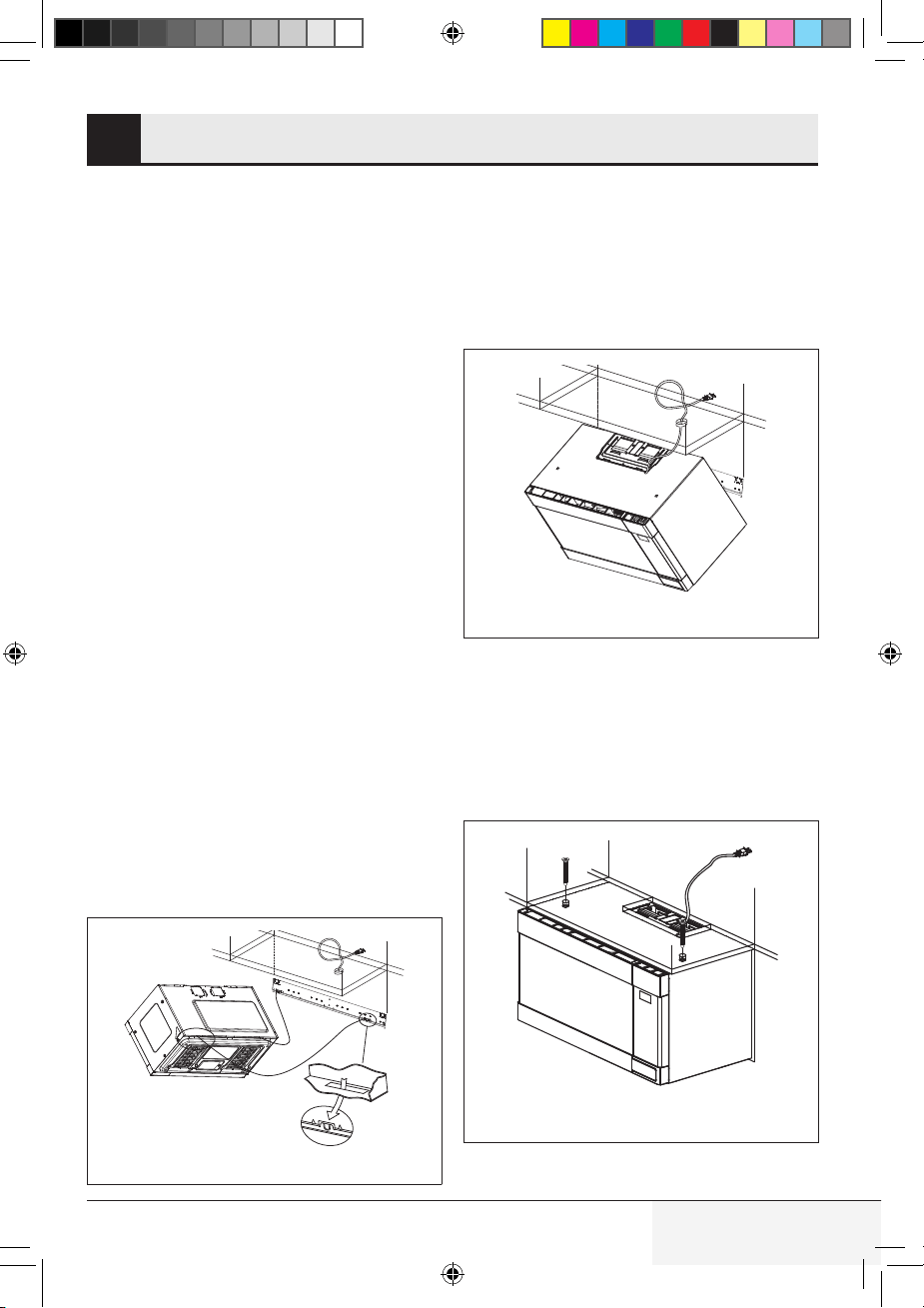
Step 2
• Lift the microwave oven and tilt it forward. Hang
the unit on two tabs at the bottom of the mount-
ing plate. See Figure 22.
Figure 22
Step 3
• Thread power cord through the hole at the
bottom of the top cabinet. Swing the unit
upward to meet the top of the mounting plate
and hold it securely. See Figure 23.
Figure 23
Step 4
• Then insert a bolt down through each hole in
the upper cabinet bottom. Tighten the bolts
until the gap between the upper cabinet and
microwave oven is closed. See Figure 24.
Figure 24
TINSKB303MRR0_MWOTR30102SS_Beko OTR_Install Manual.indd 13TINSKB303MRR0_MWOTR30102SS_Beko OTR_Install Manual.indd 13 8/19/20 2:41 PM8/19/20 2:41 PM
14 / 29 EN Over The Range Microwave Oven / Installation Manual
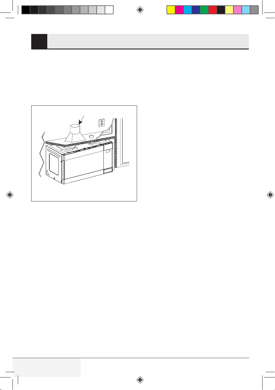
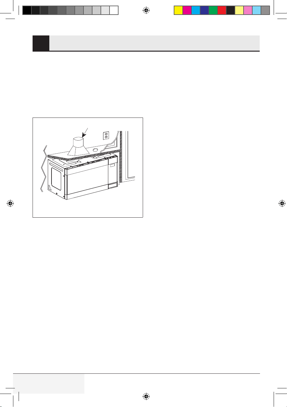
CONNECTING DUCTWORK10
• Extend the house duct down to connect to the
exhaust adapter. Seal exhaust duct joints using
duct tape. See Figure 25.
• Install the grease filters. Refer to the User Man-
ual for installation steps.
• Plug in the power cord.
House Duct
Figure 25
TINSKB303MRR0_MWOTR30102SS_Beko OTR_Install Manual.indd 14TINSKB303MRR0_MWOTR30102SS_Beko OTR_Install Manual.indd 14 8/19/20 2:41 PM8/19/20 2:41 PM

15 / 29 ENOver The Range Microwave Oven / Installation Manual
CHECK LIST FOR OPERATION11
1. Make sure the unit has been installed according to all of the installation instructions, the top cabinet
template and wall template.
2. Remove all packing material from the oven.
3. Plug in the power cord.
4. Read the User Manual.
5. Keep this Installation Manual for the local electrical inspector’s use.
TINSKB303MRR0_MWOTR30102SS_Beko OTR_Install Manual.indd 15TINSKB303MRR0_MWOTR30102SS_Beko OTR_Install Manual.indd 15 8/19/20 2:41 PM8/19/20 2:41 PM

16 / 29 FR Four à micro-ondes à hotte intégrée / Manuel d’installation
TABLE DES MATIÈRES
1 ESPACE DE MONTAGE .................... 17
2 CONSTRUCTION DU MUR ...............18
3 INSTRUCTIONS POUR LA
MISE À LA TERRE ............................19
4 CONDUIT DE SORTIE
DE LA HOTTE ...................................20
Raccordement du conduit de sortie......................20
Échappement à l’arrière .......................................20
Longueur maximale des tuyaux ...........................20
5 OUTILS RECOMMANDÉS
POUR L’INSTALLATION ...................21
6 QUINCAILLERIE
D’INSTALLATION ..............................22
7 SYSTÈME DE VENTILATION ...........23
A. Recirculation - fonctionnement non
ventilé et sans tuyau ........................................ 23
B. Système de ventilation horizontal ....................23
C. Système de ventilation vertical ........................25
8 INSTALLATION DU FOUR ................26
Plaque de montage ..............................................26
9 FIXATION DU FOUR À
MICRO-ONDES AU MUR ..................27
Préparation de l’armoire supérieure .....................27
10 CONNEXION DES CONDUITS .........28
11 LISTE DE VÉRIFICATION POUR
LE FONCTIONNEMENT ....................29
TINSKB303MRR0_MWOTR30102SS_Beko OTR_Install Manual.indd 16TINSKB303MRR0_MWOTR30102SS_Beko OTR_Install Manual.indd 16 8/19/20 2:41 PM8/19/20 2:41 PM
Veuillez lire attentivement toutes les instructions
avant d’installer le four à micro-ondes à hotte
intégrée. Deux personnes sont recommandées
pour installer ce produit.
Si une nouvelle prise électrique est requise, celle-
ci doit être effectuée par un électricien qualifié
avant d’installer le four à micro-ondes à hotte
intégrée. Voir INSTRUCTIONS DE MISE À LA
TERRE ÉLECTRIQU.
Ce four à micro-ondes à hotte intégrée nécessite
un espace de montage sur un mur, comme illus-
tré à la figure 1.
Pour une installation et un entretien corrects, un
espace de 51 mm / 2 poest nécessaire entre le
haut du dosseret de la cuisinière et le bas du four
à micro-ondes à hotte intégrée.
17 / 29 FRFour à micro-ondes à hotte intégrée / Manuel d’installation
ESPACE DE MONTAGE1
Dosseret
Min. 762 mm
(30 po)
Min. 304,8 mm (12 po)
Max. 330,2 mm (13 po)
Au moins 50,8 mm(2 po)
414 mm
(16
5
/16 po)
1676,4 mm (66 po)
ou plus, du plancher
762 mm (30 po)
ou plus, de la
surface de cuisson
Figure 1
TINSKB303MRR0_MWOTR30102SS_Beko OTR_Install Manual.indd 17TINSKB303MRR0_MWOTR30102SS_Beko OTR_Install Manual.indd 17 8/19/20 2:41 PM8/19/20 2:41 PM
18 / 29 FR Four à micro-ondes à hotte intégrée / Manuel d’installation
CONSTRUCTION DU MUR2
Ce four à micro-ondes à hotte intégrée doit être
monté contre et soutenu par une paroi verticale
plate. Le mur doit être plat pour une installation
adéquate. Si le mur n’est pas plat, utilisez des
entretoises pour remplir les écarts.
La construction du mur doit être d’au moins 51
mm x 102 mm (2 po x 4 po) et des clous en bois
de 10 mm /
3
⁄8 po ou plus épais ou de plâtre /
latte. Les surfaces de montage doivent pouvoir
supporter le poids de 50 kg (110 lb) - le four,
son contenu et le poids de tous les articles qui
devraient normalement être rangés dans l’ar-
moire supérieure au-dessus de l’appareil.
L’appareil doit être fixé à au moins un montant
mural de 51 mm x 102 mm (2 po x 4 po).
Pour trouver l’emplacement des montants, vous
pouvez utiliser l’une des méthodes suivantes :
A. Utiliser un détecteur de montant, un appareil
magnétique qui détecte les clous dans le
montant.
B. Utiliser un marteau pour taper doucement la
surface de montage jusqu’à ce qu’il produise
un son solide. Ceci indique l’emplacement
du montant.
Vous pouvez trouver le centre du montant en
sondant le mur avec un petit clou pour trouver
les rebords du montant, puis tracer une marque
au centre. Le centre des montants adjacents se
trouve normalement à 406,4 mm (16 po) ou 610
mm (24 po) de chaque côté de cette marque.
S’il est impossible de fixer l’appareil à un
montant du mur, il faudra porter une atten-
tion particulière au placement des ancrages
à boulon et des vis pour l’armoire supérieure.
Consultez le plateau du mur pour les détails.
L’armoire supérieure devrait être testée pour
vérifier qu’elle est solidement fixée au mur.
Placez jusqu’à 50 kg (110 livres) de poids supplé-
mentaire dans l’armoire supérieure pour tester sa
capacité de soutien.
Montants en bois de
51 mm x 102 mm
(2 pox 4 po)
Cloison sèche
de 10 mm (3/8 po)
ou plâtre sur lattes
381 mm (16 po) ou 9610 mm (
24 po)
Figure 2
TINSKB303MRR0_MWOTR30102SS_Beko OTR_Install Manual.indd 18TINSKB303MRR0_MWOTR30102SS_Beko OTR_Install Manual.indd 18 8/19/20 2:41 PM8/19/20 2:41 PM

Cet appareil doit être mis à la terre. Ce four est
équipé d’un cordon avec fil de mise à la terre et
une fiche pour mise à la terre. Il doit être branché
dans une prise murale installée correctement et
mise à la terre conformément au Code national
de l’électricité ainsi qu’aux codes et règlements
locaux. Dans l’éventualité d’un court-circuit, la
mise à la terre réduit le risque d’électrocution en
fournissant un fil de sortie pour le courant élec-
trique.
AVERTISSEMENT - L’utilisation inappropriée de
la prise de mise à la terre peut entraîner un risque
d’électrocution.
Le four est équipé d’une fiche de mise à la terre à
3 broches. NE JAMAIS COUPER OU ENLEVER
LA BROCHE DE MISE À LA TERRE DE LA
FICHE EN AUCUNE CIRCONSTANCE.
Le cordon d’alimentation et la fiche doivent être
connectés à une prise de courant unique de 120
volts CA, 60 Hz, 15 A ou circuit de dérivation,
mise à la terre. Le réceptacle doit être situé à
l’intérieur de l’armoire directement au-dessus de
l’emplacement de montage du four à micro-ondes
sur la cuisinière.
REMARQUE :
1. Si vous avez des questions concernant la
mise à la terre ou les instructions sur l’élec-
tricité, consultez un électricien ou technicien
qualifié.
2. Aucune responsabilité ne peut être acceptée
pour les dommages au four ou les blessures
corporelles résultant du non-respect des
procédures de connexion électrique correctes.
Prise avec
mise à la terre
Orifice pour
le cordon
d’alimentation
Figure 3
19 / 29 FRFour à micro-ondes à hotte intégrée / Manuel d’installation
INSTRUCTIONS POUR LA MISE À LA TERRE3
TINSKB303MRR0_MWOTR30102SS_Beko OTR_Install Manual.indd 19TINSKB303MRR0_MWOTR30102SS_Beko OTR_Install Manual.indd 19 8/19/20 2:41 PM8/19/20 2:41 PM
20 / 29 FR Four à micro-ondes à hotte intégrée / Manuel d’installation
CONDUIT DE SORTIE DE LA HOTTE4
Si la hotte est ventilée vers l’extérieur, un con-
duit de sortie est nécessaire. Tous les conduits
doivent être en métal; n’utilisez absolument ja-
mais de tuyauterie en plastique. Vérifiez que tous
les raccords sont fixés solidement. Veuillez lire
attentivement ce qui suit :
Raccordement du conduit de
sortie
L’échappement de la hotte a été conçu pour être
raccordé à un tuyau rectangulaire standard de
82.5 mm x 254 mm (3
1
⁄4 po x 10 po). Si un tuyau
rond est utilisé, un adaptateur de tuyau rectangu-
laire à tuyau rond devra être utilisé.
Échappement à l’arrière
Si un échappement horizontal ou vers l’arrière est
utilisé, il faut faire attention d’aligner l’échappe-
ment avec l’espace entre les montants, ou le mur
doit être préparé au moment de sa construction
pour laisser suffisamment d’espace entre les
montants pour accommoder l’échappement.
Longueur maximale des
tuyaux
Pour permettre un mouvement d’air satisfais-
ant, la longueur totale d’un tuyau rectangulaire
de 82,5 mm x 254 mm (3
1
⁄4 po x 10 po) ou d’un
tuyau rond de 152 mm (6 po) de diamètre ne
devrait pas dépasser 42,67 mètres (140 pieds).
Les coudes, adaptateurs, sorties murales et de
toit, etc., offrent une résistance supplémentaire
au mouvement de l’air et équivalent à une sec-
tion de tuyau droit plus longue que leur longueur
réelle. Lors du calcul de la longueur totale, ajou-
tez la longueur équivalente de toutes les transi-
tions et des adaptateurs à la longueur de toutes
les sections de tuyau droites. La Figure 4 montre
la longueur équivalente approximative en pieds
des pièces de conduit communes.
Utilisez les valeurs entre parenthèses pour cal-
culer la longueur totale équivalente, qui devrait
être inférieure à 42,67 mètres (140 pieds).
Coude 90˚
(304,8 cm. / 10 pi.)
Coude 45˚
(152,4 cm. / 5 pi.)
Adaptateur
(152,4 cm. / 5 pi.)
10˚ Wide elbow
(304,8 cm. / 10 pi.)
Coude 90˚
(762 cm. / 25 pi.)
Coude 45˚
(152,4 cm. / 5 pi.)
Wall cap
(1219.2 cm. / 40 pi.)
Roof cap
(731.52 cm. / 24 pi.)
Figure 4
TINSKB303MRR0_MWOTR30102SS_Beko OTR_Install Manual.indd 20TINSKB303MRR0_MWOTR30102SS_Beko OTR_Install Manual.indd 20 8/19/20 2:41 PM8/19/20 2:41 PM

21 / 29 FRFour à micro-ondes à hotte intégrée / Manuel d’installation
OUTILS RECOMMANDÉS POUR L’INSTALLATION
5
• Tournevis Phillips
• Perceuse électrique
• Ciseaux
• Crayon
• Ruban à mesurer
• Ruban adhésif
• Foret pour bois ou foret emporte-pièce pour le métal (si armoire en métal) de 38 mm (1 1⁄2 po)
• Forets de 12,7 mm (1⁄2 po), 15,8 mm (5⁄8 po) et 2,3 mm (3⁄32 po)
• Scie pour découper l’orifice d’échappement (si nécessaire)
• Linge ou tissu de protection pour l’appareil et la cuisinière; vous pouvez aussi utiliser un carton
TINSKB303MRR0_MWOTR30102SS_Beko OTR_Install Manual.indd 21TINSKB303MRR0_MWOTR30102SS_Beko OTR_Install Manual.indd 21 8/19/20 2:41 PM8/19/20 2:41 PM
22 / 29 FR Four à micro-ondes à hotte intégrée / Manuel d’installation
QUINCAILLERIE D’INSTALLATION6
La liste qui suit comprend les pièces dont vous pourriez avoir besoin pour installer votre four à mi-
cro-ondes à hotte intégrée. La quincaillerie d’installation est fournie dans un sac accompagnant l’ap-
pareil. Assurez-vous d’avoir toutes ces pièces en votre possession. Profitez-en pour vous familiariser
avec chacune des pièces.
Article Nom de la pièce Qté
1
1
Vis tire-fond - 6,3 mm x 45,7 mm (
1
⁄4 po x 1
13
⁄16 po) 2
2
Boulons et écrous à ailettes -
4,7 mm x 68,6 mm (
3
⁄16 po x 2
11
⁄16 po)
2
3
Boulons de montage à l’armoire -
6,3 mm x 79 mm (
1
⁄4 po x 3
1
⁄8 po)
2
4
4
Rondelle - 19 mm (
3
⁄4 po) 2
5
Passe-câble en nylon (pour armoires en métal) 1
6
6
Clapet 1
7
7
Plaque de montage 1
Figure 5
TINSKB303MRR0_MWOTR30102SS_Beko OTR_Install Manual.indd 22TINSKB303MRR0_MWOTR30102SS_Beko OTR_Install Manual.indd 22 8/19/20 2:41 PM8/19/20 2:41 PM
23 / 29 FRFour à micro-ondes à hotte intégrée / Manuel d’installation
SYSTÈME DE VENTILATION7
Ce four à micro-ondes à hotte intégrée est conçu
pour s’adapter à trois types de systèmes de ven-
tilation à hotte. Sélectionnez le type requis pour
votre installation.
A. Recirculation -
fonctionnement non ventilé
et sans tuyau
L’appareil est expédié prêt à être utilisé en mode
de recirculation.
REMARQUE :
1. Le clapet de sortie n’est pas nécessaire pour
le fonctionnement en mode de recirculation.
2. Le filtre à charbon devrait être remplacé tous
les six mois, selon la fréquence d’utilisation.
3. Le filtre à charbon est aussi vendu en tant
qu’accessoire. Voir le Manuel d’utilisation pour
des détails sur le processus de commande.
B. Système de ventilation
horizontal
Étape 1
• Retirez les vis (1) et (2) pour ouvrir le couvercle
du moteur du ventilateur et conservez ces vis.
Retirez le couvercle. Voir la figure 6.
Couvercle du moteur
du ventilateur
Arrière du four
Figure 6
Étape 2
• Retirez les vis (3) de fixation du ventilateur et
conservez les vis. Voir la figure 7.
Avant : Ouvertures du ventilateur orientées vers l’avant
Figure 7
• Soulevez le ventilateur et retirez-le de l’em-
placement de montage. Voir la figure 8.
MISE EN GARDE : Ne tirez pas et n’étirez pas
les fils du ventilateur.
Moteur du
ventilateur
Figure 8
TINSKB303MRR0_MWOTR30102SS_Beko OTR_Install Manual.indd 23TINSKB303MRR0_MWOTR30102SS_Beko OTR_Install Manual.indd 23 8/19/20 2:41 PM8/19/20 2:41 PM
24 / 29 FR Four à micro-ondes à hotte intégrée / Manuel d’installation
SYSTÈME DE VENTILATION7
Étape 3
• Tournez le ventilateur afin que les ouvertures
du ventilateur soient tournées vers l’arrière (de
l’appareil). Voir la figure 9.
MISE EN GARDE : Les fils du ventilateur doivent
être acheminés correctement avant la réinstalla-
tion de la plaque pour éviter les pincements.
Après : Ouvertures du ventilateur vers l’arrière
Tournez le moteur du ventilateur 180˚ en sens horaire
Figure 9
• Utilisez une pince coupante diagonale ou
une cisaille à tôle pour découper et retirer les
pièces B de la plaque arrière. Faites attention
de ne pas déformer la plaque. Voir la figure 10.
Pièces B
Figure 10
Étape 4
• Placez le ventilateur dans l’ouverture et fixez-le
au four avec les vis (3) de l’étape 2. Voir la fig-
ure 11.
Figure 11
• Alignez précisément l’ouverture du four à mi-
cro-ondes et le clapet et fixez ce dernier à la
plaque arrière en le glissant dans les guides
de la plaque arrière. Voir les figures 12 et 13.
• Assurez-vous que la charnière du clapet est en
haut et que le clapet bascule librement dans la
sortie murale.
Clapet
Figure 12
Figure 13
TINSKB303MRR0_MWOTR30102SS_Beko OTR_Install Manual.indd 24TINSKB303MRR0_MWOTR30102SS_Beko OTR_Install Manual.indd 24 8/19/20 2:41 PM8/19/20 2:41 PM
25 / 29 FRFour à micro-ondes à hotte intégrée / Manuel d’installation
SYSTÈME DE VENTILATION7
C. Système de ventilation
vertical
Étape 1 & 2
A-1 Moteur de ventilation. Voir la section B,
étapes 1 et 2 pour accéder au moteur du ventila-
teur. Voir également la figure 8.
Step 3
• Tournez le vent teur afin que les sorties soient
tournées vers le haut. Voir la figure 14.
Sorties du ventilateur orientées
vers le haut
Après l’avoir
tourné
Arrière du four
à micro-ondes
Figure 14
Étape 4
• Placez le ventilateur dans l’ouverture. Fixez le
couvercle du moteur du ventilateur au four à 1,
2 et 3) des étapes 1 et 2. Voir la figure 15.
Figure 15
• Faites correspondre avec soin l’emplacement
de l’orifice d’évacuation du four à micro-ondes
et fixez l’amortisseur au capot du moteur du
ventilateur en le faisant glisser dans les guides
situés sur le capot du moteur du ventilateur.
Voir les figures 16-2 et 17.
• Assurez-vous que la charnière de l’amortisseur
est à l’avant et que l’amortisseur bascule libre-
ment dans la sortie verticale.
Figure 16
Figure 17
TINSKB303MRR0_MWOTR30102SS_Beko OTR_Install Manual.indd 25TINSKB303MRR0_MWOTR30102SS_Beko OTR_Install Manual.indd 25 8/19/20 2:41 PM8/19/20 2:41 PM
26 / 29 FR Four à micro-ondes à hotte intégrée / Manuel d’installation
INSTALLATION DU FOUR8
Ce four ne peut pas être installé correctement
sans consulter les instructions de montage im-
primées sur les deux gabarits.
Lisez et suivez les informations de montage im-
primées sur les gabarits pour l’armoire supérieure
et le mur.
Plaque de montage
Étape 1- Position de montage
• Tracez une ligne le long du centre des montants.
Voir Construction du mur, page 4.
• Tracez une ligne verticale sur le mur au centre
de l’espace de 30 po. Voir la figure 18.
REMARQUE : Utilisez le PLATEAU DU MUR
pour le mur arrière. Reportez-vous au PLATEAU
DU MUR avant de poursuivre. L’installation de ce
produit nécessite le concours de deux personnes.
A
C
C
B
C
C
Orifice pour le cordon d'alimentation
Conduit de la maison
Plaque de montage
Figure 18
Étape 2 - Perçage des trous
• Reportez-vous au plateau du mur.
Étape 3 - Serrage des vis
Pour fixer la plaque de montage au mur, utilisez
les ensembles de boulon à ailettes et/ou les vis
tire-fond :
• Insérez les boulons à travers la plaque de mon-
tage aux emplacements déterminés et ajoutez
les ailettes à ressort. Voir la figure 19.
Assurez-vous de laisser un espace d’au moins
l’épaisseur du mur entre la plaque de mon-
tage et la fin de l’écrou à ailettes (en position
fermée). Si vous ne laissez pas cet espace,
l’écrou à ailettes ne pourra pas s’ouvrir de l’au-
tre côté du mur.
Plaque de montage
Figure 19
• Mettez en place la plaque de montage sur le
mur et insérez les boulons à ailettes assem-
blés dans les trous percés dans le mur ou
commencez à visser les vis tire-fond dans le(s)
montant(s) du mur. Voir la Figure 20.
Cloison sèche
Espace plus grand que l’épaisseur du mur
Figure 20
• Fixez la plaque de montage au mur en serrant
les boulons à ailettes ou les vis tire-fond. Voir
la figure 21.
• Percez un ou des trous de 3/16 po de diamètre
dans le ou les montants pour le(s) vis tire-fond.
Qu’il devrait y avoir au moins une vis tirefond dans
un montant. Pour déterminer l’emplacement des
montants, consultez construction du mur.
• Serrez la/les vis tire-fond dans le(s) montant(s).
Figure 21
TINSKB303MRR0_MWOTR30102SS_Beko OTR_Install Manual.indd 26TINSKB303MRR0_MWOTR30102SS_Beko OTR_Install Manual.indd 26 8/19/20 2:41 PM8/19/20 2:41 PM
27 / 29 FRFour à micro-ondes à hotte intégrée / Manuel d’installation
FIXATION DU FOUR À MICRO-ONDES AU MUR9
IMPORTANT : Ne tenez ou n’utilisez pas la poi-
gnée pendant l’installation.
Préparation de l’armoire
supérieure
Vous devez percer des trous pour les vis de mon-
tage supérieures et un trou suffisamment grand
pour y passer le cordon d’alimentation.
• Lisez les instructions sur le plateau pour plac-
ard supérieur.
• Fixez le gabarit sous l’armoire à l’aide de ruban
adhésif.
• Percez les trous conformément aux instruc-
tions sur le gabarit.
REMARQUE : les instructions imprimées sur le
plateau pour placard supérieur doivent être com-
plétées avant de poursuivre.
Étape 1
• Protégez la surface de votre cuisinière en
plaçant une partie de la boîte en carton ou
un autre matériau épais sur celle-ci avant de
procéder à l’installation du four à micro-ondes.
Étape 2
• Soulevez le four à micro-ondes et inclinez-le
vers l’avant. Accrochez-le aux deux languettes
situées à la base de la plaque de montage. Voir
la figure 22.
Figure 22
Étape 3
• Acheminez le cordon d’alimentation à travers
l’orifice dans la base de l’armoire supérieure.
Basculez l’appareil vers le haut pour qu’il re-
joigne le dessus de la plaque de montage et
tenez-le fermement. Voir la figure 23.
Figure 23
Étape 4
• Insérez ensuite un boulon dans chacun des trous
percés dans l’armoire supérieure. Serrez les
boulons jusqu’à ce que l’écart entre l’armoire et
le four à micro-ondes se referme complètement.
Voir la figure 24.
Figure 24
TINSKB303MRR0_MWOTR30102SS_Beko OTR_Install Manual.indd 27TINSKB303MRR0_MWOTR30102SS_Beko OTR_Install Manual.indd 27 8/19/20 2:41 PM8/19/20 2:41 PM
28 / 29 FR Four à micro-ondes à hotte intégrée / Manuel d’installation
CONNEXION DES CONDUITS10
• Abaissez le conduit de la maison pour le raccorder
à l’adaptateur d’échappement. Scellez les joints
du tuyau de sortie avec du ruban à conduits.
Voir la figure 25.
• Installez les filtres à graisse. Reportez-vous au
guide d’installation pour les étapes d’installation.
• Branchez le cordon d’alimentation.
Conduit de la maison
Figure 25
TINSKB303MRR0_MWOTR30102SS_Beko OTR_Install Manual.indd 28TINSKB303MRR0_MWOTR30102SS_Beko OTR_Install Manual.indd 28 8/19/20 2:41 PM8/19/20 2:41 PM
29 / 29 FRFour à micro-ondes à hotte intégrée / Manuel d’installation
LISTE DE VÉRIFICATION POUR LE FONCTIONNEMENT
11
1. Vérifier que l’appareil a été installé conformément à toutes les instructions d’installation et celles du
plateau pour placard supérieur et du plateau du mur.
2. Le cas échéant, retirer du four le matériel d’emballage restant.
3. Brancher le cordon d’alimentation.
4. Lire le manuel d’utilisation.
5. Garder toutes les guide d’installation à l’intention de l’inspecteur en électricité.
TINSKB303MRR0_MWOTR30102SS_Beko OTR_Install Manual.indd 29TINSKB303MRR0_MWOTR30102SS_Beko OTR_Install Manual.indd 29 8/19/20 2:41 PM8/19/20 2:41 PM

TINSKB303MRR0_MWOTR30102SS_Beko OTR_Install Manual.indd 30TINSKB303MRR0_MWOTR30102SS_Beko OTR_Install Manual.indd 30 8/19/20 2:41 PM8/19/20 2:41 PM
TINSKB303MRR0_MWOTR30102SS_Beko OTR_Install Manual.indd 31TINSKB303MRR0_MWOTR30102SS_Beko OTR_Install Manual.indd 31 8/19/20 2:41 PM8/19/20 2:41 PM
www.beko.com
TINSKB303MRR0_MWOTR30102SS_Beko OTR_Install Manual.indd 32TINSKB303MRR0_MWOTR30102SS_Beko OTR_Install Manual.indd 32 8/19/20 2:41 PM8/19/20 2:41 PM