
Contents
Contents
MOTORCYCLE SAFETY............................. 1
Important Safety Information ........................... 2
Important Safety Precautions ........................ 2
Accessories & Modifications ........................... 3
Accessories & Modifications ........................ 3
Off-Road Safety ............................................... 4
Off-Road Safety ............................................ 4
Safety Labels .................................................... 5
INSTRUMENTS & CONTROLS.................. 7
Operation Component Locations ...................... 8
Indicators & Displays ....................................... 9
Multi-function Display................................ 10
Speedometer ................................................ 12
Odometer/Tripmeter A & B ........................ 12
Fuel Mileage Meter ..................................... 12
Digital Clock Setting................................... 13
Backlight Brightness Adjustment................ 13
Changing the Speed and Mileage Unit........ 14
Changing the Fuel Mileage Unit ................. 14
Controls & Features ........................................ 15
Ignition Switch ............................................ 15
Start Button ................................................. 15
Engine Stop Switch ..................................... 15
Headlight Dimmer Switch........................... 15
Passing Light Control Switch...................... 15
Turn Signal Switch...................................... 15
Horn Button................................................. 15
BEFORE RIDING......................................... 17
Are You Ready to Ride? ................................ 18
Always carry this manual and tool kit......... 18
Protective Apparel....................................... 18
Rider Training ............................................. 18
Is Your Motorcycle Ready to Ride? ............... 19
Pre-ride Inspection ...................................... 19
Load Limits & Guidelines .............................. 21
Loading........................................................ 21
Load Limits ................................................. 21
Loading Guidelines ..................................... 21
BASIC OPERATING INSTRUCTIONS.....23
Basic Operating Instructions ...........................24
Safe Riding Precautions...............................24
Carbon Monoxide Hazard............................24
Starting & Stopping the Engine ......................25
Fast Idle Knob..............................................25
Preparation ...................................................25
Starting Procedure........................................25
Bank Angle Sensor Ignition Cut-off System...26
How to Stop the Engine...............................26
Shifting Gears .................................................27
Braking ............................................................28
Parking ............................................................29
Theft-prevention Tips ..................................29
Break-in Guidelines ........................................30
SERVICING YOUR HONDA ......................31
The Importance of Maintenance .....................32
Maintenance Safety .........................................33
Important Safety Precautions.......................33
Periodic Maintenance ......................................34
Maintenance Schedule ....................................35
Maintenance Record (On-Road Use Only) .....38
General Competition Maintenance
(Off-Road Use Only) ......................................39
Before & After Competition Maintenance
(Off-Road Use Only) ......................................43
Between Races & Practice Maintenance .....43
After Competition Maintenance ..................44
Service Preparations
Maintenance Component Locations ...............45
Seat ..................................................................46
Side Cover .......................................................47
Fuel Tank ........................................................48
Subframe .........................................................52
Service Procedures
Fluids & Filters
Fuel System ....................................................60
Fuel.............................................................. 60
Refueling Procedure.................................... 60
Fuel Line Inspection.................................... 61
Fuel Line Replacement................................ 61
Fuel Pump Filter Replacement.................... 63
Fuel Pressure Increasing.............................. 68
Engine Oil ....................................................... 69
Oil Recommendation................................... 69
Checking & Adding Oil .............................. 70
Changing Engine Oil & Filter ..................... 70
Coolant ........................................................... 72
Coolant Recommendation ........................... 72
Checking & Adding Coolant....................... 72
Cooling System Inspection.......................... 73
Coolant Replacement .................................. 73
Cooling System Bleed Air........................... 74
Air Cleaner ..................................................... 75
Cleaning....................................................... 75
Crankcase Breather ......................................... 77
Draining....................................................... 77
Engine
Throttle ........................................................... 78
Throttle Freeplay ......................................... 78
Throttle Inspection ...................................... 79
Throttle Cable Lubrication .......................... 79
Engine Idle Speed ........................................... 80
Idle Speed Adjustment ................................ 80
Clutch System ................................................. 81
Clutch Lever Freeplay................................. 81
Other Inspections......................................... 82
Clutch Operation ......................................... 82
Clutch Cable Lubrication ............................ 82
Clutch Disc/Plate Removal ......................... 83
Clutch Disc/Plate/Spring Inspection ........... 84
Clutch Disc/Plate Installation...................... 84
Spark Plug ...................................................... 86
Spark Plug Recommendation ...................... 86
Spark Plug Inspection & Replacement........ 86
2019 CRF450L
31MKE900
MOM 16640 (1803)

Contents
Contents
Valve Clearance ............................................. 87
Cylinder Head Cover Removal ................... 87
Positioning At TDC On The Compression
Stroke ..........................................................88
Valve Clearance Inspection......................... 89
Camshaft Removal ...................................... 89
Shim Selection............................................. 91
Camshaft Installation................................... 92
Crankshaft Hole Cap Installation ................ 94
Cylinder Head Cover Installation................ 95
Piston/Piston Rings/Piston Pin ....................... 96
Cylinder Head Removal .............................. 96
Cylinder Removal ....................................... 98
Piston Removal ........................................... 98
Piston Ring Removal................................... 98
Piston/Piston Pin/Piston Ring Inspection.... 99
Piston Ring Installation ............................... 99
Piston Installation...................................... 100
Cylinder Installation.................................. 101
Cylinder Head Installation ........................ 102
Chassis
Suspension .................................................... 105
Front Suspension Inspection ..................... 105
Front Suspension Removal........................ 106
Recommended Fork Oil ............................ 108
Fork Outer Tube Disassembly................... 108
Fork Oil Refilling ...................................... 109
Front Suspension Installation .................... 110
Fork Damper Disassembly ........................ 113
Damper Oil Change................................... 115
Fork Damper Installation .......................... 118
Rear Suspension Inspection ...................... 121
Brakes ........................................................... 122
Front Brake Lever Adjustment.................. 122
Rear Brake Pedal Height ........................... 122
Fluid Level Inspection............................... 123
Brake Pad Wear......................................... 125
Other Inspections....................................... 125
Brake Light Adjustment............................ 125
Wheels ...........................................................126
Wheel Rims & Spokes...............................126
Axles & Wheel Bearings ...........................126
Tires & Tubes ...............................................127
Air Pressure................................................127
Inspection...................................................127
Tube Replacement .....................................127
Tire Replacement.......................................128
Side Stand .....................................................129
Drive Chain ...................................................130
Inspection...................................................130
Drive Chain Sliders....................................130
Drive Chain Rollers ...................................131
Adjustment.................................................131
Lubrication.................................................131
Removal, Cleaning & Replacement...........132
Exhaust Pipe/Muffler ....................................133
Exhaust Pipe/Muffler Inspection ...............133
Muffler Removal........................................133
Muffler Installation ....................................133
Exhaust Pipe Removal ...............................134
Exhaust Pipe Installation ...........................134
Spark Arrester ...............................................135
Spark Arrester Inspection ..........................135
Additional Maintenance Procedures .............136
Steering Head Bearing Inspection .............136
Handlebar Inspection .................................136
Control Cables ...........................................136
Nuts, Bolts, Fasteners ................................137
Electrical
Battery .......................................................... 138
Battery Storage .......................................... 138
Battery Charging ....................................... 139
Headlight Aim .............................................. 140
Headlight Aim Vertical Adjustment.......... 140
Appearance Care .......................................... 141
General Recommendations........................ 141
Washing Your Motorcycle with a Mild
Detergent ................................................... 141
After Cleaning Lubrication ....................... 142
Panels......................................................... 142
Aluminum Frame Maintenance................. 142
Titanium Fuel Tank Maintenance ............. 142
Exhaust Pipe and Muffler Maintenance .... 142
ADJUSTMENTS ......................................... 143
Front Suspension Adjustments ..................... 144
Front Suspension Air Pressure .................. 144
Front Suspension Damping ....................... 145
Rear Suspension Adjustments ...................... 146
Rear Suspension Spring Pre-Load
(Off-Road Use Only)................................. 146
Rear Suspension Damping ........................ 147
Rear Suspension Race Sag
(Off-Road Use Only)................................. 148
Suspension Adjustment Guidelines
(Off-Road Use Only) .................................... 150
Tuning Tips .................................................. 153
Spark Plug Reading (Off-Road Use Only)....153
Chassis Adjustments ..................................... 154
Rear End (Off-Road Use Only)................. 154
Fork Height/Angle (Off-Road Use Only) .....154
Wheelbase (Off-Road Use Only) .............. 154
Tire Selection for Track Conditions
(Off-Road Use Only) .................................... 155
Personal Fit Adjustments .............................. 156
Control Positioning (Off-Road Use Only) ....156
Handlebar Position (Off-Road Use Only).....156

2019
Honda CRF450L
OWNER’S MANUAL & OFF-ROAD HANDBOOK
Introduction
Introduction
Introduction
Congratulations on choosing your Honda
motorcycle.
When you own a Honda, you’re part of a
worldwide family of satisfied customers – people
who appreciate Honda’s reputation for building
quality into every product.
Before riding, take time to get acquainted with
your motorcycle and how it works. To protect your
investment, we urge you to take responsibility for
keeping your motorcycle well maintained.
Scheduled service is a must, of course. But it’s just
as important to observe the break-in guidelines,
and perform all the pre-ride and other periodic
checks detailed in this manual.
You should also read the owner’s manual before
you ride. It’s full of facts, instructions, safety
information, and helpful tips. To make it easy to
use, the manual contains a table of contents, a
detailed list of topics at the beginning of each
section, and an index at the back of the book.
As you read this manual, you will find information
that is preceded by a symbol. This
information is intended to help you avoid damage
to your motorcycle, other property, or the
environment.
Unless you are mechanically qualified and have
the proper tools, you should see your dealer for the
service and adjustment procedures discussed in
this manual.
An official Honda Service Manual for your
motorcycle is available (page 194). It is the same
manual your dealer uses. If you plan to do any
service on your motorcycle beyond the standard
maintenance procedures in this manual, you will
find an official Honda Service Manual a valuable
reference.
Read the Warranties Booklet (page 195)
thoroughly so you understand the coverages that
protect your new Honda and are aware of your
rights and responsibilities.
If you have any questions, or if you ever need a
special service or repairs, remember that your
Honda dealer knows your motorcycle best and is
dedicated to your complete satisfaction.
Please report any change of address or ownership
to your dealer so we will be able to contact you
concerning important product information.
You may also want to visit our website at
USA: www.powersports.honda.com.
Canada: www.honda.ca.
Happy riding!
ABBREVIATION
Throughout this manual, the following
abbreviations are used to identify the respective
parts or system.
Abbrev. term Full term
CKP sensor Crankshaft Position sensor
DLC Data Link Connector
DTC Diagnostic Trouble Code
ECM Engine Control Module
ECT sensor Engine Coolant Temperature
sensor
IAT sensor Intake Air Temperature sensor
MAP sensor Manifold Absolute Pressure sensor
MIL Malfunction Indicator Lamp
PGM-FI Programmed Fuel Injection
TDC Top Dead Center
TP sensor Throttle Position sensor

Safety Messages
A Few Words About Safety
Your safety, and th
e safety of others, is very important. Operating this motorcycle safely is an important responsibility.
To help you make informed decisions about safety, we have provided operating procedures and other information on labels and in this manual.
This information alerts you to potential hazards that could hurt you or others.
Of course, it is not practical or possible to warn you about all hazards associated with operating or maintaining a motorcycle. You must use your own good
judgment.
You will find important safety information in a variety of forms, including:
• Safety Labels — on the motorcycle.
• Safety Messages — preceded by a safety alert symbol and one of three signal words: DANGER, WARNING, or CAUTION.
These signal words mean:
• Safety Headings — such as Important Safety Reminders or Important Safety Precautions.
• Safety Section — such as Motorcycle Safety.
• Instructions — how to use this motorcycle correctly and safety.
This entire manual is filled with important safety information — please read it carefully.
You WILL be KILLED or SERIOUSLY HURT if you don’t follow instructions.
You CAN be KILLED or SERIOUSLY HURT if you don’t follow instructions.
You CAN be HURT if you don’t follow instructions.
DANGER
WARNING
CAUTION

Contents
Contents
TIPS .............................................................. 157
Transporting Your Motorcycle ..................... 158
Storing Your Honda ..................................... 159
Preparation for Storage.............................. 159
Removal from Storage .............................. 159
You & the Environment ............................... 160
Troubleshooting ............................................ 161
TAKING CARE OF THE UNEXPECTED163
Taking Care of the Unexpected .................... 164
General Guidelines.................................... 164
If Your Engine Quits or Won’t Start ............ 165
If You Have a Flat Tire ................................ 167
Should You Repair or
Replace a Tire or Tube? ............................ 167
Emergency Front Wheel
Removal/Installation ................................. 167
Emergency Rear Wheel
Removal/Installation ................................. 169
If the High Coolant Temperature
Indicator Lights ............................................ 170
If You Have a Burned-out Light Bulb .......... 171
Burned-out Light Bulb .............................. 171
If a Fuse Blows ............................................. 172
If You Crash ................................................. 173
If You Lose Your Key .................................. 174
If Your Battery Is Low (or Dead) ................. 175
TECHNICAL INFORMATION.................177
Vehicle Identification ....................................178
Serial Numbers ..........................................178
Specifications ................................................179
Torque Specifications ...................................181
Nuts, Bolts, Fasteners ................................181
Emission Control Systems ............................184
Exhaust Emission Requirements ...............184
Noise Emission Requirements...................184
Exhaust Emission Control System.............184
Evaporative Emission Control System ......184
Crankcase Emission Control System.........184
Fuel Permeation Emission Control System...184
Noise Emission Control System ................185
Problems Affecting Motorcycle Exhaust
Emissions ...................................................185
Catalytic Converter .......................................186
Oxygenated Fuels ..........................................187
Off-Road Logbook ........................................188
Optional Parts List ........................................190
Spare Parts & Equipment ..............................191
Spare Parts .................................................191
General Tools.............................................191
Honda Special Tools..................................191
Chemical Products .....................................191
Other Products ...........................................191
Wiring Diagram ............................................192
CONSUMER INFORMATION ................. 193
Authorized Manuals ..................................... 194
Warranty Coverage ....................................... 195
Warranty Service .......................................... 196
Contacting Honda ......................................... 197
Your Honda Dealer ....................................... 198
Reporting Safety Defects (USA only) .......... 199
INDEX .......................................................... 200
Quick Reference ........................................... 207
How To Avoid Costly Repairs .................. 207
Quick Reference ........................................... 208

Motorcycle Safety
Motorcycle Safety 1
This section presents some of the most important
information and recommendations
to help you ride
your motorcycle safely. Please take a few moments
to read these pages. This section also includes
information about the location of safety labels on
your motorcycle.
Important Safety Information ............................2
Important Safety Precautions.........................2
Accessories & Modifications.............................3
Off-Road Safety .................................................4
Safety Labels......................................................5

Important Safety Information
2 Motorcycle Safety
Important Safety Information
Your motorcycle can provide many years of
service and pleasure, if you take responsibility for
your own safety and understand the challenges you
can meet while riding.
There is much that you can do to protect yourself
when you ride. You’ll find many helpful
recommendations throughout this manual. The
following are a few that we consider to be most
important.
Always Wear a Helmet.
It’s a proven fact: helmets and protective apparel
significantly reduce the number and severity of
head and other injuries. So always wear an
approved motorcycle helmet and protective
apparel (page 18).
Never Carry a Passenger.
Your motorcycle is designed for one person only.
There are no handholds, footrests, or seat for a
second person–so never carry a passenger. A
passenger could interfere with your ability to move
around to maintain your balance and control of the
motorcycle.
Take Time to Learn & Practice
Even if you have ridden other motorcycles,
practice riding in a safe area to become familiar
with how this motorcycle works and handles, and
to become accustomed to the motorcycle’s size
and weight.
We recommend that all riders take a certified
course approved by the Motorcycle Safety
Foundation (MSF). New riders should start with
the basic course, and even experienced riders will
find the advanced course beneficial.
For information about the MSF training course
nearest you, call the national toll-free number:
(800) 446-9227.
Other riding tips can be found in the You and Your
Motorcycle Riding Tips booklet that came with
your motorcycle (USA only).
Developing off-road riding skill a gradual step-by
step process. Start by practicing at low speeds in a
safe area and slowly build your skills.
Ask your dealer if there are off-road riding groups
in your area where you can learn from experienced
riders. Also be sure to read Tips & Practice Guide
for the Off-Highway Motorcyclist that came with
your new motorcycle.
Ride Defensively
Always pay attention to other vehicles around you,
and do not assume that other drivers see you. Be
prepared to stop quickly or perform an evasive
maneuver.
Make Yourself Easy to See
Make yourself more visible, especially at night, by
wearing bright reflective clothing, positioning
yourself so other drivers can see you, signaling
before turning or changing lanes, and using your
horn when necessary.
Be Alert for Off-road Hazards
The terrain can be present a variety of challenges
when you ride off-road. Continually “read” the
terrain for unexpected turns, drop-offs, rocks, ruts
and other hazards. Always keep your speed low
enough to allow time to see and react to hazards.
Ride within Your Limits
Never ride beyond your personal abilities or faster
than conditions warrant. Fatigue and inattention
can impair your ability to use good judgment and
ride safely.
Don’t Drink and Ride.
Alcohol and riding don't mix. Even one alcoholic
drink can reduce your ability to respond to
changing conditions, and your reaction time gets
worse with every additional drink. Don't drink and
ride, and don't let your friends drink and ride
either.
Keep your Honda in Safe Condition.
It’s important to keep your motorcycle properly
maintained and in safe riding condition. Having a
breakdown can be difficult, especially if you are
stranded off-road far from your base. Follow the
loading guidelines (page 21), and do not modify
your motorcycle (page 3) or install accessories that
would make your motorcycle unsafe (page 3).
Lithium-Ion (Li-Ion) Battery.
If you smell an unusual odor coming from the
lithium-ion (li-ion) battery, park your motorcycle
in a safe place outside and away from flammable
objects, then turn the ignition switch to the OFF
position. Have your motorcycle inspected by your
dealer immediately.
Important Safety Precautions
Accessories & Modifications
Motorcycle Safety 3
We strongly advise that you do not add any
accessories that were not specifically designed or
approved for your motorcycle by Honda or make
modifications to your motorcycle from its original
design. Doing so can make it unsafe.
Modifying your motorcycle may also void your
warranty and make your motorcycle illegal to
operate on public roads and highways. Before
deciding to install accessories on your motorcycle
be certain the modification is safe and legal.
Do not pull a trailer with, or attach a sidecar to,
your motorcycle. Your motorcycle was not
designed for these attachments, and their use can
seriously impair your motorcycle's handling.
Do not attempt modify the motorcycle to carry a
passenger. The subframe was not designed to carry
the additional weight of a passenger.
Accessories & Modifications
WARNING
Improper accessories or modifications
can cause a crash in which you can be
seriously hurt or killed.
Follow all instructions in this owner’s
manual regarding accessories and
modifications.
Off-Road Safety
4 Motorcycle Safety
Off-Road Safety
Learn to ride in an uncongested off-road area free
of obstacles before venturing onto unfamiliar
terrain.
• Always obey local off-road riding laws and
regulations.
• Obtain permission to ride on private property.
Avoid posted areas and obey “NO Trespassing”
signs.
• Ride with a friend on another motorcycle so that
you can assist each other in case of trouble.
• Familiarity with your motorcycle is critically
important should a problem occur far from help.
• Never ride beyond your ability and experience or
faster than conditions warrant.
• If you are not familiar with the terrain, ride
cautiously. Hidden rocks, holes, or ravines could
spell disaster.
• A muffler is required in most off-road areas.
Don't modify your exhaust system. Remember
that excessive noise bothers everyone and
creates a bad image for motorcycling.
Off-Road Safety
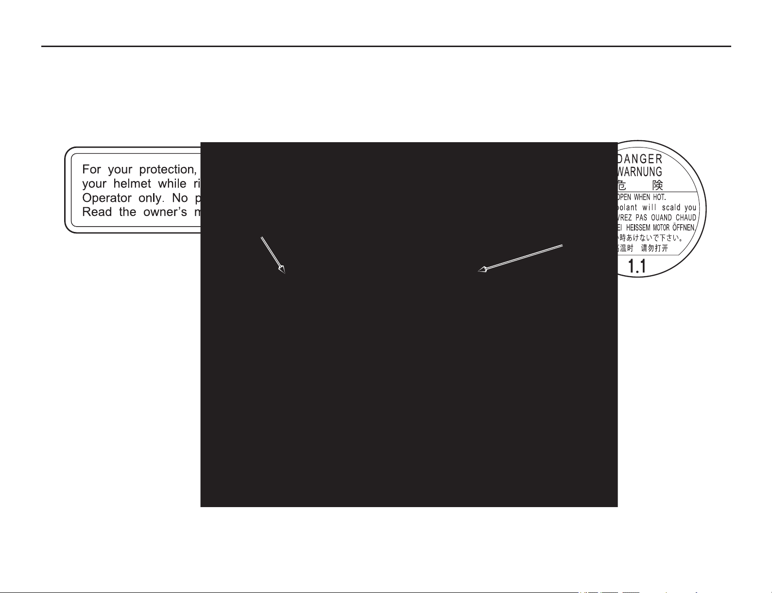
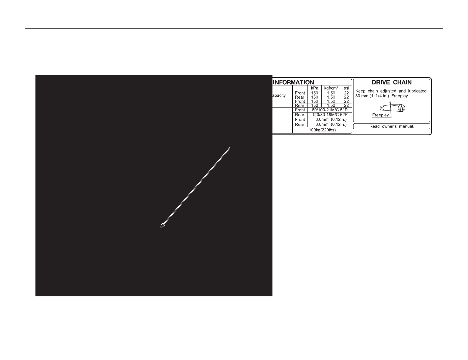
Safety Labels
Motorcycle Safety 5
Safety and information labels on your motorcycle provide important safety information and may warn you of potential hazards that could cause serious injury.
Read these labels carefully and don't remove them.
If a label comes off or becomes hard to read, contact your dealer for replacement.
Safety Labels
6 Motorcycle Safety

Instruments & Controls
Instruments & Controls 7
This section shows the location of all indicators,
and controls you would
normally use before or
while riding your motorcycle.
The items listed on this page are described in this
section. Instructions for other components are
presented in other sections of this manual where
they will be most useful.
Operation Component Locations .......................8
Indicators & Displays ........................................9
Multi-function Display ................................10
Speedometer.................................................12
Odometer/Tripmeter A & B.........................12
Fuel Mileage Meter......................................12
Digital Clock Setting ...................................13
Backlight Brightness Adjustment ................13
Changing the Speed and Mileage Unit ........14
Changing the Fuel Mileage Unit..................14
Controls & Features .........................................15
Ignition Switch.............................................15
Start Button ..................................................15
Engine Stop Switch......................................15
Headlight Dimmer Switch ...........................15
Passing Light Control Switch ......................15
Turn Signal Switch ......................................15
Horn Button .................................................15
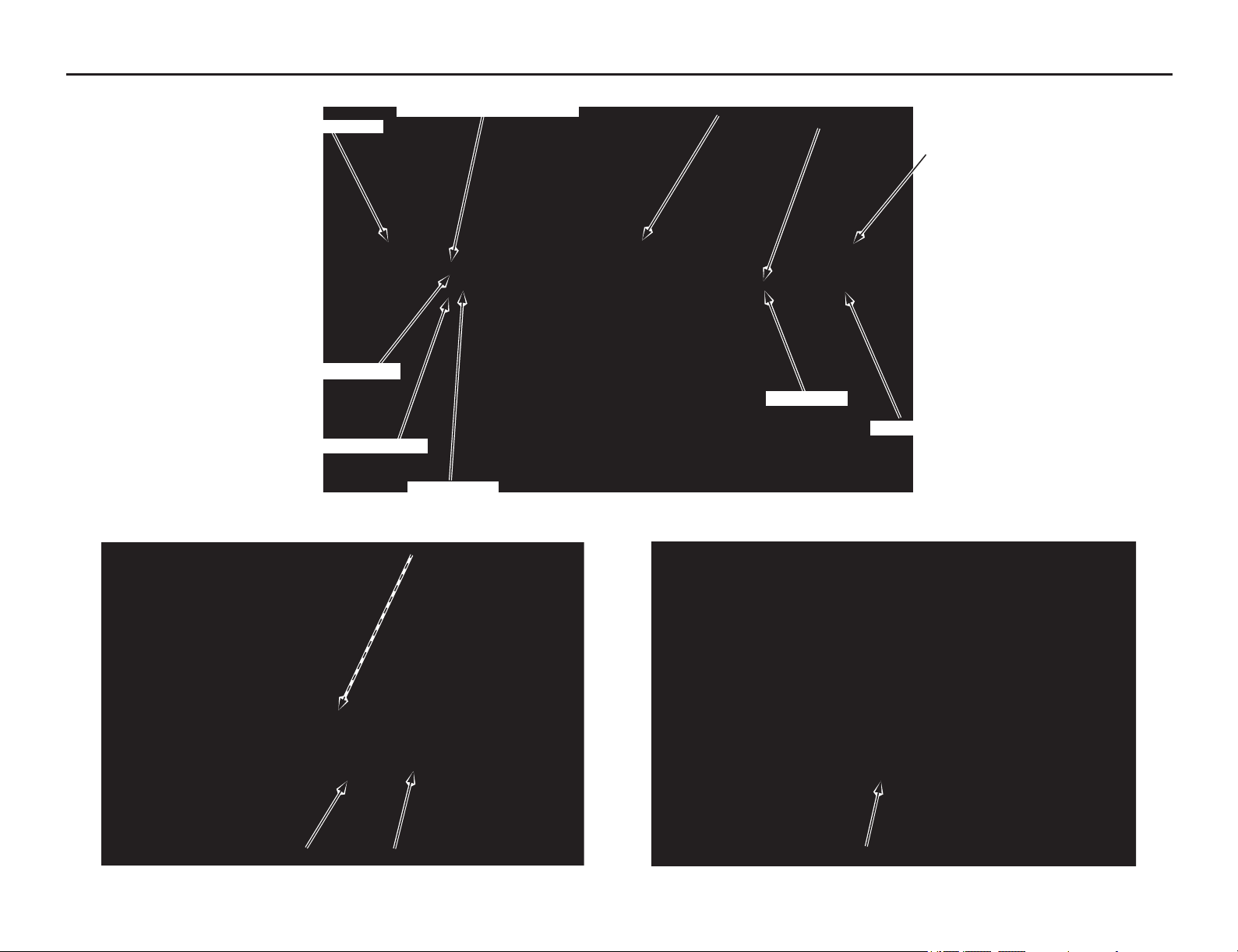
Operation Component Locations
8 Instruments & Controls
front brake lever
clutch lever
headlight dimmer switch
passing light control switch
turn signal switch
start button
throttle grip
ignition switch
horn button
engine stop switch
shift lever
fast idle knob (engine idle speed)
side stand
rear brake pedal
Indicators & Displays
(cont’d)
Instruments & Controls 9
The indicators and display on your motorcycle
keep you
informed, alert you to possible problems,
and make your riding safer and more enjoyable.
Refer to the indicators and display frequently.
Their functions are described on the following
pages.
Lamp Check
Most of the indicator lights come on when you
turn the ignition switch ON so you can check
that they are working. Some indicators turn off
after a few seconds.
When applicable, the high beam and neutral
indicators come on when you turn the ignition
switch ON and remain on until you select the
low beam or shift out of neutral.
These indicators are identified in the table on
page 10 with the words: Lamp Check.
If one of these indicators does not come on
when it should, have your dealer check for
problems.
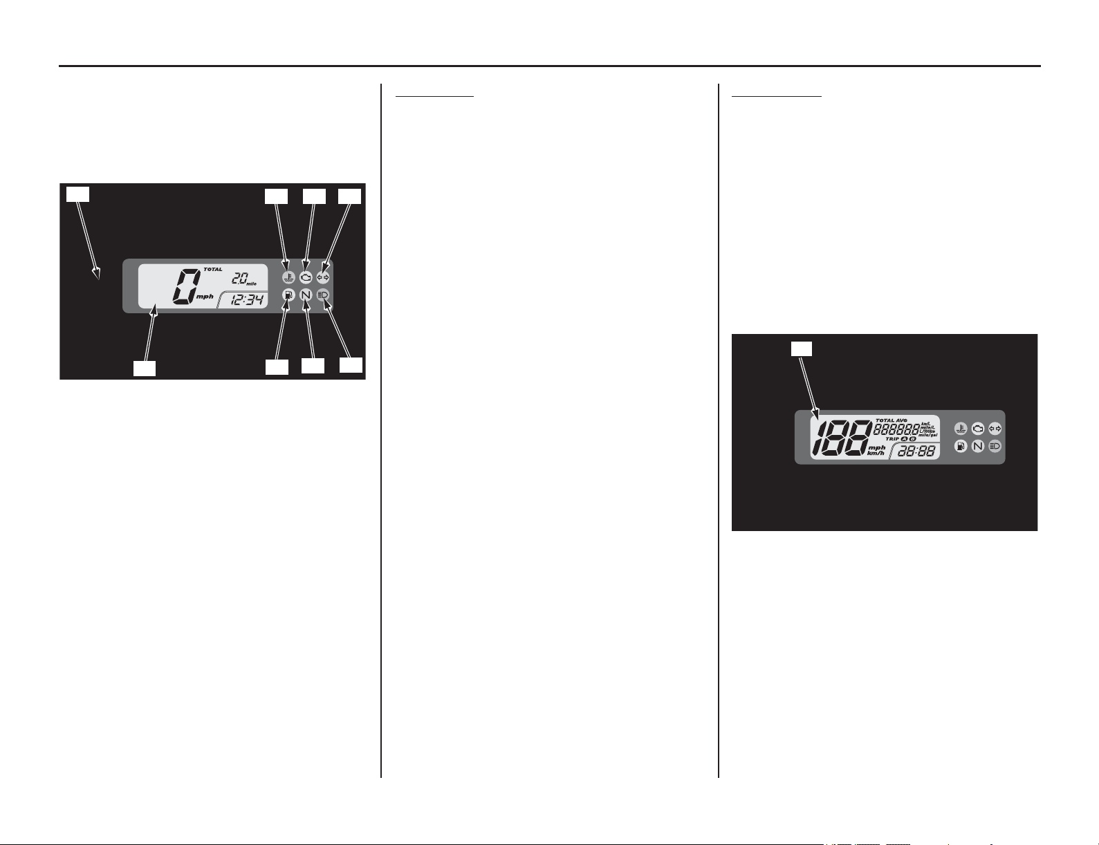
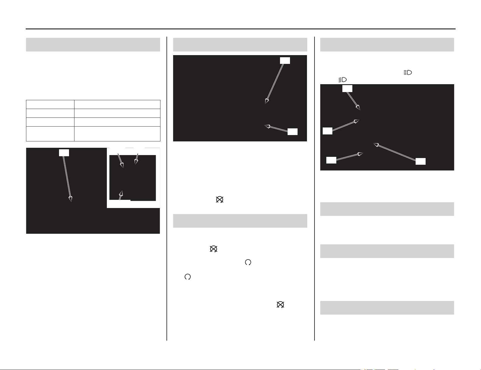
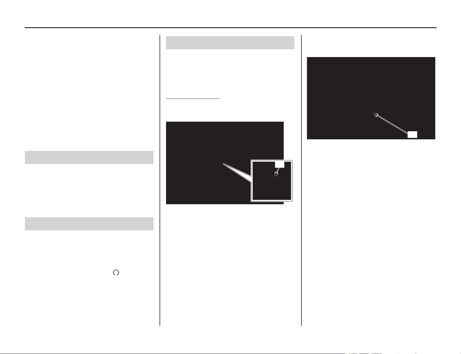
Display Check
When the ignition switch is turned ON, the
multi-function display (1) will temporarily
show all the modes and digital segments so
that you can make sure the liquid crystal
display is functioning properly.
The displays are identified in the table on
page 10 with the words: Display Check.
If any part of these displays does not come on
when it should, have your dealer check for
problems.
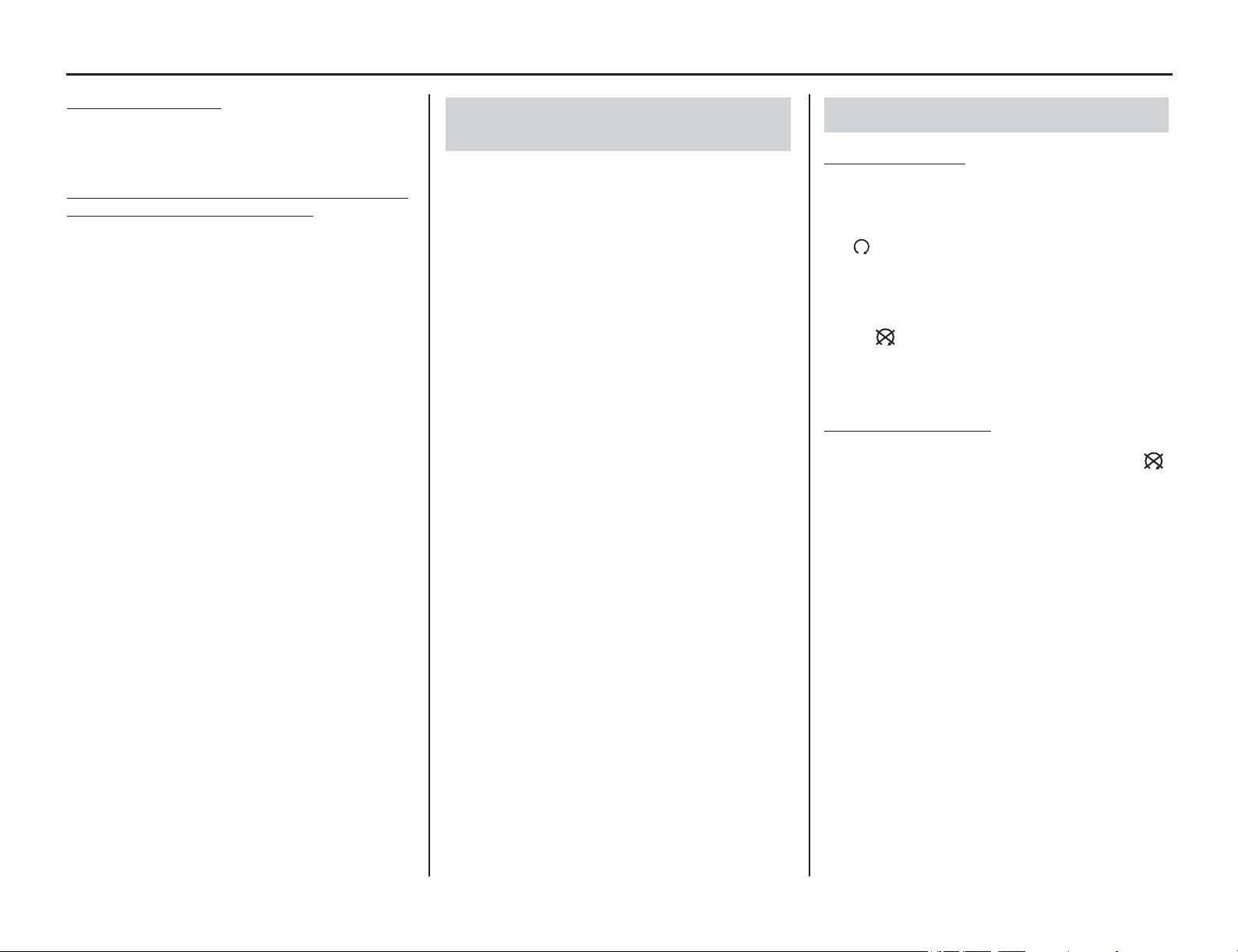
(1) SEL button
(2) high coolant temperature indicator
(3) PGM-FI (Programmed Fuel Injection) malfunction
indicator lamp (MIL)
(4) turn signal indicator
(5) multi-function display
(6) fuel reserve indicator
(7) neutral indicator
(8) high beam indicator
(1)
(5)
(8)
(7)
(6)
(2) (3) (4)
(1) multi-function display
(1)
10 Instruments & Controls
Indicators & Displays
1 SEL button Uses this button for the following purposes.
• To change the 12/24 hour
• To adjust time
• To adjust display illumination
• To select and reset the fuel mileage meter
• To change the mileage units for the odometer/tripmeter and available
driving distance
• To select and reset the tripmeter
2 High coolant temperature
indicator
Lights when the coolant is over the specified temperature.
If the indicator comes on, pull safely to the side of the road.
See page 170. Lamp Check.
3 PGM-FI (Programmed Fuel
Injection) malfunction indicator
lamp (MIL)
Lights when there is any abnormality in the PGM-FI (Programmed Fuel
Injection) system. Should also light for a few seconds and then go off when
the ignition switch is turned ON and the engine stop switch is at (Run)
position. If the indicator comes on at any other time, reduce speed and take
your motorcycle to your dealer as soon as possible. Lamp Check.
4 Turn signal indicator Flashes when either turn signal operates.
5 Multi-function display The display includes the following functions. Display check.
Speedometer Shows riding speed in miles or kilometers per hour (page 12).
Digital clock Shows hour and minute (page 13).
Odometer Shows accumulated mileage (page 12).
Tripmeter A & B Shows the number of miles or kilometers ridden since you last reset the
meter (page 12).
Fuel mileage meter Shows current fuel mileage, average fuel mileage, or fuel consumption
(page 12).
6 Fuel reserve indicator When this indicator comes on while riding, fuel reserved in the tank is about:
0.58 US gal (2.2 ℓ)
Lamp Check.
7 Neutral indicator Lights when the transmission is in neutral.
8 High beam indicator Lights when the headlight is on high beam.
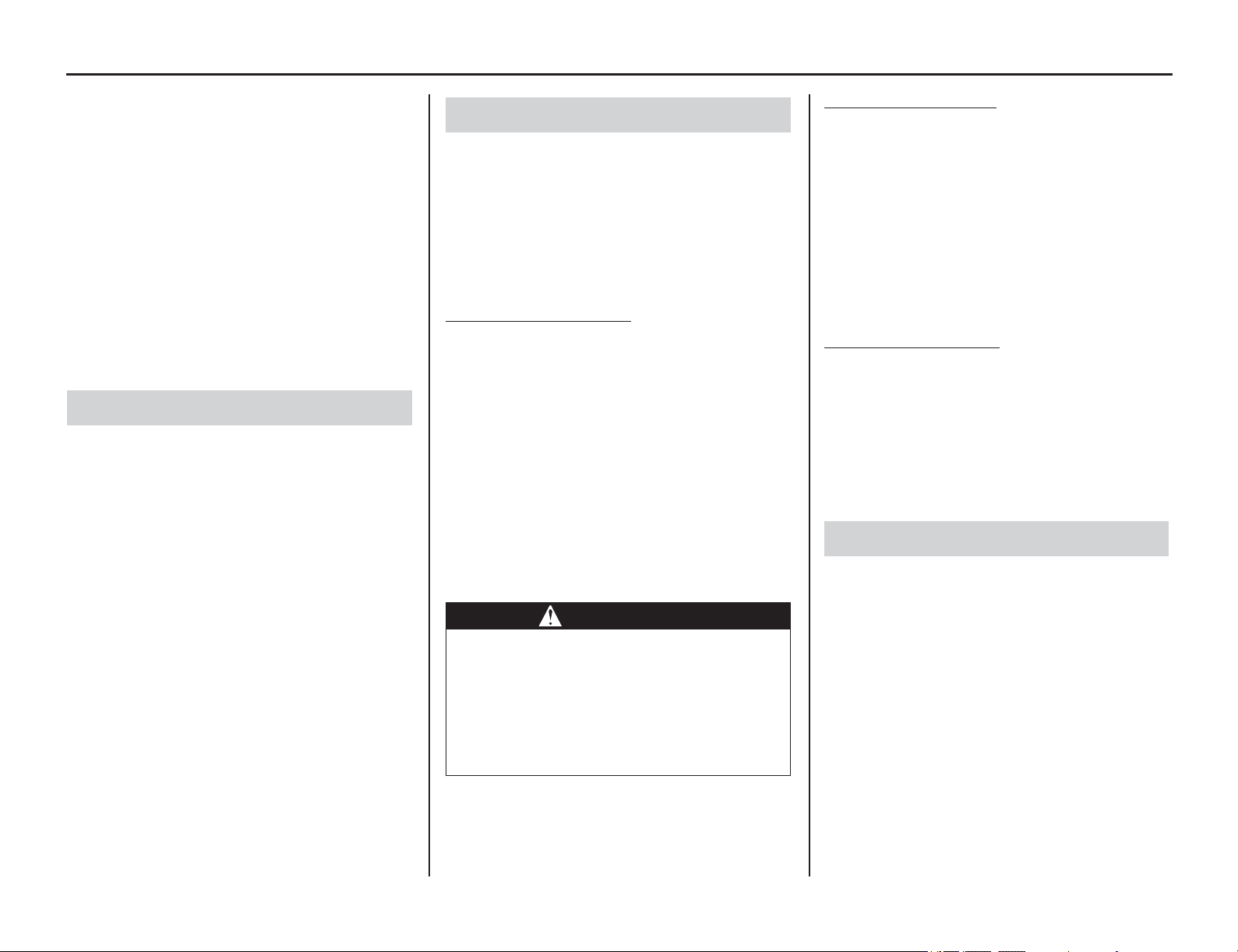
The multi-function display includes the following
functions:
speedometer
odometer
tripmeter A & B
fuel mileage meter
digital clock
The digital clock will reset if the battery is
disconnected.
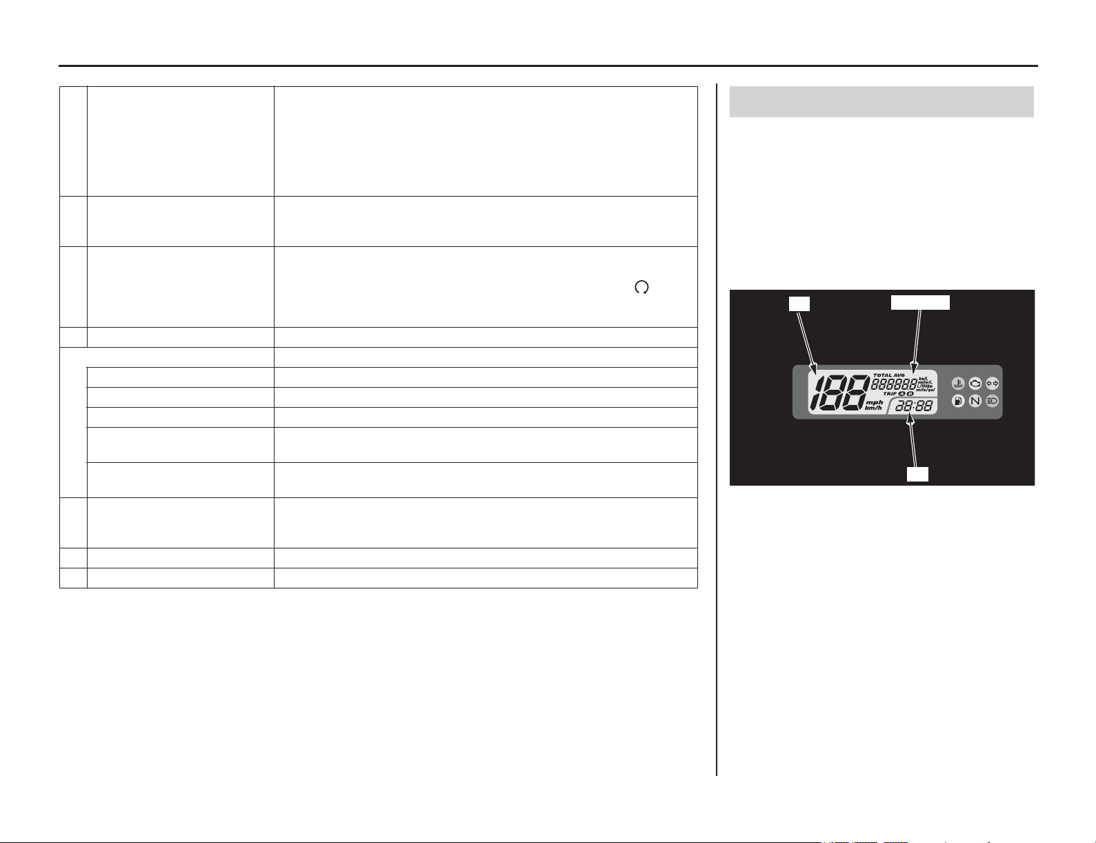
Multi-function Display
(1) speedometer
(2) odometer
(3) tripmeter
(4) fuel mileage meter
(5) digital clock
(1)
(2)(3)(4)
(5)
Instruments & Controls 11
Indicators & Displays
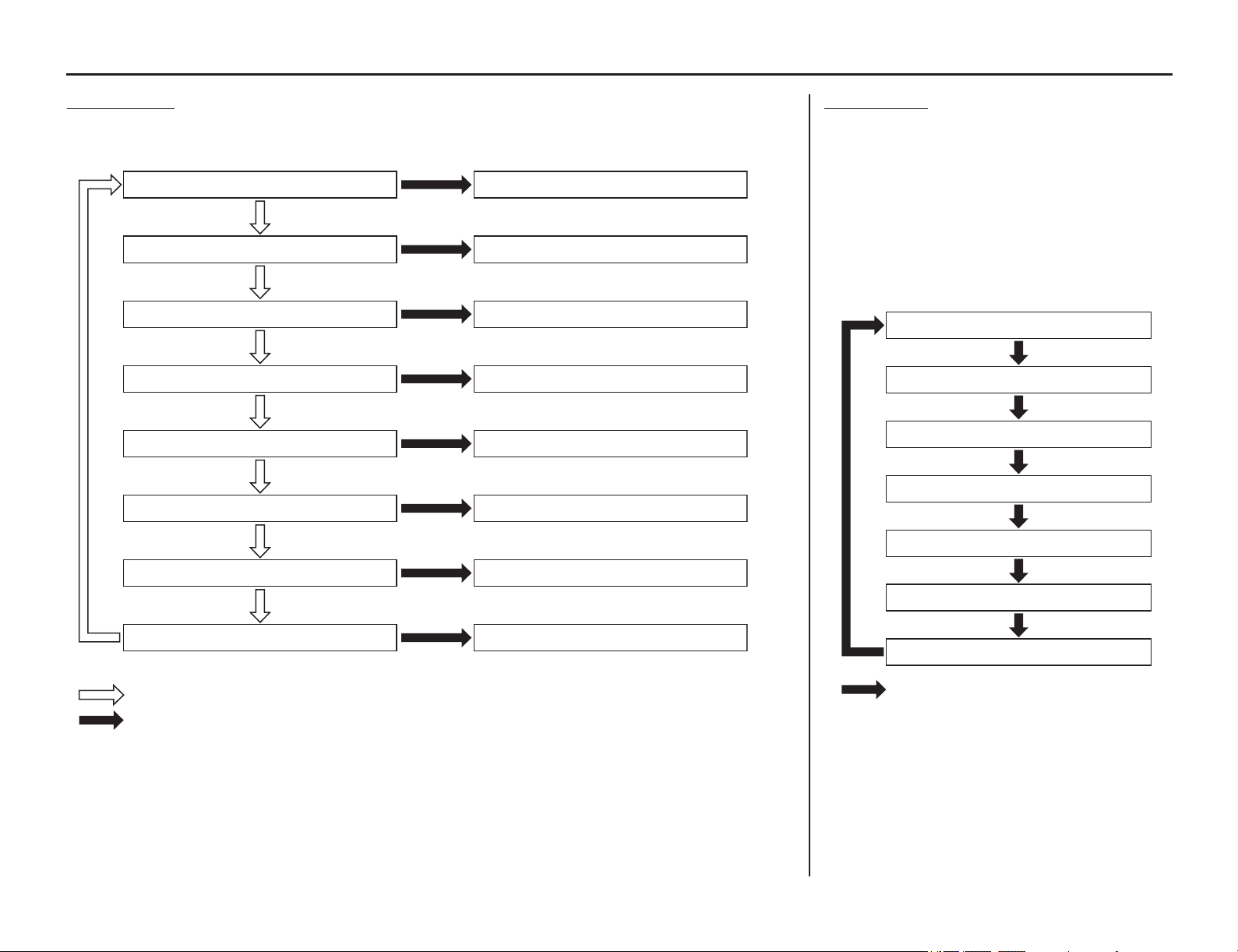
Normal MODE
Press the SEL button to select the Odometer, TRIP A, TRIP B, Current fuel mileage, Average fuel
mileage (TRIP A/TRIP B) or Fuel consumption (TRIP A/TRIP B).
Odometer [TOTAL]
TRIP A
TRIP B
Current fuel mileage
Average fuel mileage (TRIP A)
To setting mode
Resetting the meter (page 12)
Resetting the meter (page 12)
To setting mode
Resetting the meter (page 12)
Resetting the meter (page 12)
Resetting the meter (page 12)
Resetting the meter (page 12)
Press SEL button
Press and hold SEL button
Average fuel mileage (TRIP B)
Fuel consumption (TRIP A)
Fuel consumption (TRIP B)
Setting MODE
Press and hold the SEL button, the display turn
into the setting mode.
Following items can be changed sequentially.
• Time format setting
• Clock setting
• Backlight brightness adjustment
• Changing of speed and mileage unit
• Changing of fuel mileage unit
In addition, to move the ordinary display at
display setting.
• The buttons is not pressed for about 30
seconds.
• Turn the ignition switch to the OFF position
and then to the ON position.
Normal mode
12 Hour or 24 Hour
Backlight brightness adjustment
Speed and Mileage unit setting
Hour setting
Minute setting
Fuel Mileage unit setting
Press and hold SEL button
12 Instruments & Controls
Indicators & Displays
The speedometer shows riding speed in miles or
kilometers per hour.
The odometer shows the total miles or kilometers
ridden.
The odometer can be displayed from 0 to 999,999
miles (kilometers).
The tripmeter A and tripmeter B show number of
miles or kilometers ridden since you last reset the
tripmeter.
To select the odometer, tripmeter A or tripmeter B,
push the SEL button (1).
The tripmeter return to 0 when the read-out
exceeds 9,999.9 miles (kilometers).
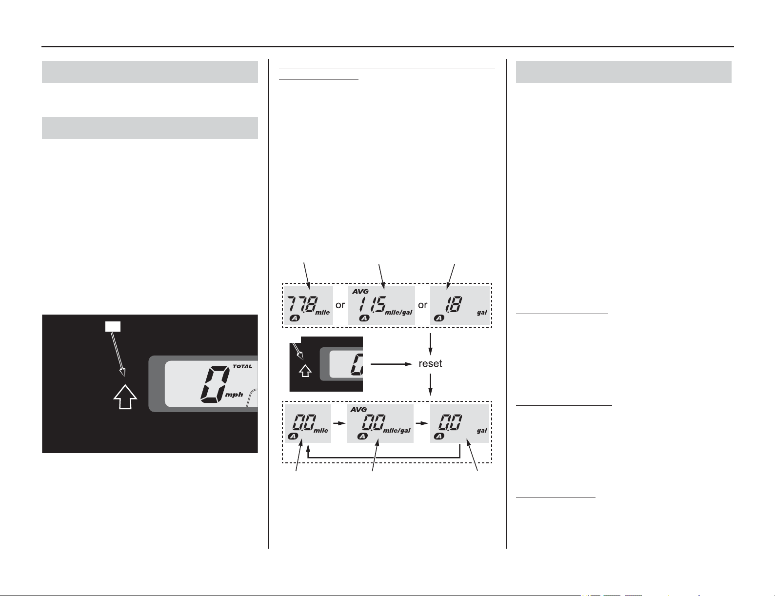
To Reset
the Tripmeter, Average Fuel Mileage and
Fuel Consumption
Press the SEL button (1) to select the TRIP A (2),
average fuel mileage A (3), fuel consumption A
(4), TRIP B, average fuel mileage B or fuel
consumption B.
To reset tripmeter, average fuel mileage, and fuel
consumption, press and hold SEL button with
tripmeter, average fuel mileage, or fuel
consumption displayed.
When they are reset, reset display appears at each
indication. Then, the display returns to the last
selected indication.
The fuel mileage meter includes the following
functions:
current fuel mileage
average fuel mileage
fuel consumption
The unit of the indication depends on the unit
which you select (page 14).
If the speed and mileage unit is set to ‘‘km/h’’/‘‘km,’’
the indication mode of the current and average fuel
mileage can be selected km/L or L/100 km (page 14).
If the speed and mileage unit is set to ‘‘mph’’/
‘‘mile’’, the fuel mileage unit shows “mile/gal”.
Press the SEL button to change the indication to
the current fuel mileage, average fuel mileage A,
average fuel mileage B, fuel consumption A or fuel
consumption B.
Current Fuel Mileage
Current fuel mileage shows the current, or instant
fuel mileage you are getting. When your
motorcycle speed is 4 mph (6 km/h) or below,
“---.- (--.-)” is displayed. When “---.- (--.-)” is
displayed except for the above mentioned cases, go
to your dealer for service.
Average Fuel Mileage
The average fuel mileage is based on the each
tripmeter A and tripmeter B. The average fuel
mileage since tripmeter was reset. When
“---.- (--.-) ” is displayed, see your dealer for
service. Average fuel mileage is also reset when
the tripmeter is reset (see previous step).
Fuel Consumption
The fuel consumption is based on the each
tripmeter A and tripmeter B. The fuel consumption
since tripmeter was reset. When “---.-” is
displayed, see your dealer for service.
Speedometer
Odometer/Tripmeter A & B
(1) SEL button
(1)
(1) SEL button (3) fuel mileage A
(2) TRIP A (4) fuel consumption A
(2)
For example TRIP A, Average Fuel Mileage A and
Fuel Consumption A:
(3)
(4)
(2)
(3)
(4)
(1)
Fuel Mileage Meter
Instruments & Controls 13
Indicators & Displays
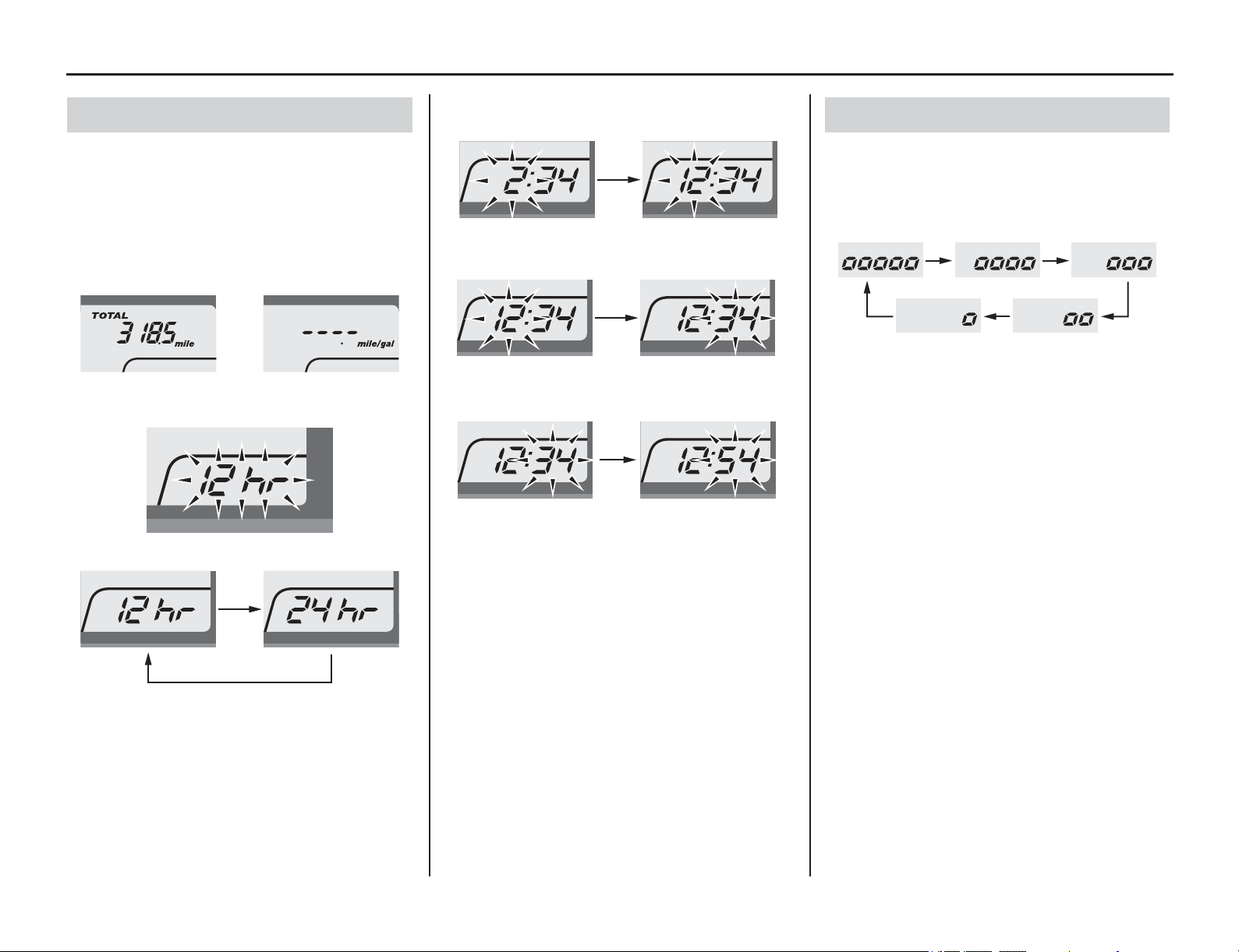
The digital clock shows the hour and minute. To
adjust the time format and clock, proceed as
follows:
1. Turn the ignition switch ON.
2. Press SEL button to select the odometer or
current fuel mileage.
3. Press and hold SEL button until the current
time format start flashing.
4. Press SEL button to select “12 hr” or “24 hr”.
5. Press and hold SEL button. The time format is
set, and then the display moves to the clock
setting.
6. Press SEL button until the desired hour is
displayed.
7. Press and hold SEL button. The minute digits
start flashing.
8. Press SEL button until the desired minute is
displayed.
9. Press and hold SEL button. The clock is set,
and then the display moves to the backlight
brightness adjustment.
The established setting can also be set by turning
the ignition switch to the OFF position.
The control is automatically switched from the
setting mode to the normal mode if the button is
not pressed for about 30 seconds. Even in this case,
established setting is maintained.
To adjust the backlight brightness, proceed as
follows:
1. Refer to Digital Clock on previous step.
2. Press SEL button. The brightness is switched.
3. Press and hold SEL button. The backlight is
set, and then the display moves the changing of
the speed and mileage unit.
The established setting can also be set by turning
the ignition switch to the OFF position.
The control is automatically switched from the
setting mode to the normal mode if the button is
not pressed for about 30 seconds. Even in this case,
established setting is maintained.
Digital Clock Setting
Odometer: Current fuel mileage:
or
Backlight Brightness Adjustment
14 Instruments & Controls
Indicators & Displays
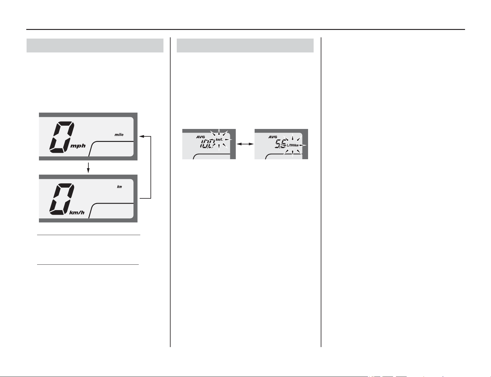
To adjust the Speed and Mileage Unit proceed as
follows:
1. Refer to Backlight Brightness Adjustment on
previous step.
2. Press SEL button to select either “mph” and
“mile” or “km/h” and “km”.
3. W
hen selecting the “mph” and “mile”
Press and hold SEL button. The speed and
mileage unit is set, and then the display will
return to the normal mode.
When selecting the “km/h” and “km”
Press and hold SEL button. The speed and
mileage unit is set, and then the display moves
the changing of the fuel mileage unit.
The established setting can also be set by turning
the ignition switch to the OFF position.
The control is automatically switched from the
setting mode to the normal mode if the button is
not pressed for about 30 seconds. Even in this case,
established setting is maintained.
If the “mph” for speed and “mile” for mileage are
selected, the fuel mileage unit cannot be select.
To adjust the Fuel Mileage Unit proceed as
follows:
1. Refer to Changing the Speed and Mileage Unit
on previous step.
2. Press SEL button to switch between “km/L” or
“L/100km”.
3. Press and hold SEL button. The fuel mileage
unit is set, and then the display will return to
the normal mode.
The established setting can also be set by turning
the ignition switch to the OFF position.
The control is automatically switched from the
setting mode to the normal mode if the button is
not pressed for about 30 seconds. Even in this case,
established setting is maintained.
Changing the Speed and Mileage Unit Changing the Fuel Mileage Unit
Controls & Features
Instruments & Controls 15
The ignition switch (1) is used for starting and
stopping the engine (page 26) and to lock the
steering for theft prevention (page 29). Insert the
key and turn it to the right for the ON position.
Push down on the key and turn it to the left to the
LOCK (steering lock) position.
Leaving the ignition switch in the ON position
with the engine stopped will drain the battery.
Do not turn the key while riding.
The start button (1) is used for starting the engine.
Pushing the button in starts the engine. See
Starting Procedure, page 25.
The starter motor will not operate if the engine stop
switch is in the (Stop) position when the start
button is pushed.
The engine stop switch (2) is used to stop the
engine in an emergency. To operate, push the
switch to the (Stop) position.
The switch must be in the (Run) position to
start the engine, and it should normally remain in
the (Run) position even when the engine is
OFF.
If your motorcycle is stopped with the ignition
switch ON and the engine stop switch (Stop)
position, the headlight, position light, taillight and
license light will remain on, resulting in battery
discharge.
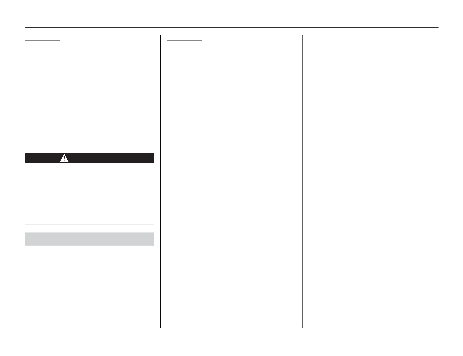
The headlight dimmer switch (1) is used to change
between the high and low beams of the headlight.
To operate, press the switch to (HI) for high
beam, (Lo) for low beam.
When this switch (2) is pressed, the headlight
flashes on to signal approaching cars or when
passing.
The turn signal switch (3) is used to signal a turn or
a lane change. To operate, move the switch all the
way in the proper direction and release it. The
appropriate turn signal lights will start blinking. To
cancel the light, push the switch in.
The horn is used to alert other motorists.
To operate, push the horn button (4).
Ignition Switch
Key Position Function
ON Electrical circuits on.
OFF No electrical circuits function.
LOCK
(steering lock)
No electrical circuits function.
Locks the steering head.
(1) ignition switch
(1)
ONOFF
LOCK
Start Button
(1) start button (2) engine stop switch
Engine Stop Switch
(1)
(2)
Headlight Dimmer Switch
(1) headlight dimmer switch
(2) passing light control switch
(3) turn signal switch
(4) horn button
Passing Light Control Switch
Turn Signal Switch
Horn Button
(1)
(2)
(3)
(4)

16 Instruments & Controls
BLANK PAGE

Before Riding
Before Riding 17
Before each ride, you need to make sure
you and
your motorcycle are both ready to ride. To help get
you prepared, this section discusses how to
evaluate your riding readiness, what items you
should check on your motorcycle, and adjustments
to make for your comfort, convenience, or safety.
This section also includes important information
about loading.
For information about suspension and other
adjustments, see page 143.
Are You Ready to Ride? ..................................18
Always carry this manual and tool kit .........18
Protective Apparel .......................................18
Rider Training..............................................18
Is Your Motorcycle Ready to Ride? ................19
Pre-ride Inspection.......................................19
Load Limits & Guidelines ...............................21
Loading ........................................................21
Load Limits..................................................21
Loading Guidelines......................................21
Are You Ready to Ride?
18 Before Riding
Are You Ready to Ride?
Before you ride your motorcycle for the first time,
we urge you to:
• Read this owner’s manual
• Make sure you understand all the safety
messages
• Know how to operate all the controls
Before each ride, be sure:
• You feel well and are in good physical and
mental condition.
• You are wearing an approved motorcycle
helmet (with chin strap tightened securely),
eye protection, and other protective clothing.
• You don’t have any alcohol or drugs in your
system.
This owner's manual and tool kit cannot be stored
on this motorcycle. Be sure to carry the owner's
manual and tool kit with you when riding.
For your safety, we strongly recommend that you
always wear an approved motorcycle helmet, eye
protection, boots, gloves, long pants and a long-
sleeved shirt or jacket whenever you ride.
Although complete protection is not possible,
wearing proper gear can reduce the chance of
injury when you ride. Following are suggestions to
help you choose the proper gear.
Helmet and Eye Protection
Your helmet is your most important piece of riding
gear because it offers the best protection against
head injuries. A helmet should fit your head
comfortably and securely. A bright-colored helmet
and reflective strips can make you more noticeable
in traffic.
An open-face helmet offers some protection, but a
full-face helmet offers more. Always wear a face
shield or goggles to protect your eyes and help
your vision.
Lock for a DOT (Department of Transportation)
certification label on any helmet you buy (USA
only).
Additional On-road Gear
In addition to a helmet and eye protection, we also
recommend:
• Sturdy boots with non-slip soles to help protect
your feet and ankles.
• Leather gloves to help protect your hands.
• A motorcycle riding suit or jacket for comfort
as well as protection. Bright-colored and
reflective clothing can help make you more
noticeable in traffic. Avoid loose clothes that
could get caught on any part of your
motorcycle.
Additional Off-road Gear
On-road apparel may also be suitable for casual
off-road riding. But if you plan on any serious off-
road riding you will need more serious off-road
gear. In addition to your helmet and eye protection,
we recommend off-road motorcycle boots and
gloves, riding pants with knee and hip pads, a
jersey with elbow pads, and a chest/shoulder
protector.
Developing your riding skills is an on-going
process. Even if you have ridden other
motorcycles, take time to become familiar with
how this motorcycle works and handles. Practice
riding the motorcycle in a safe area to build your
skills. Do not ride in traffic until you get
accustomed to the motorcycle’s controls, and feel
comfortable with its size and weight.
We urge all riders to take a motorcycle operator
course. New riders should start with the basic
course, and even experienced riders will find the
advanced course beneficial.
Always carry this manual and tool kit
Protective Apparel
WARNING
Not wearing a helmet increases the
chance of serious injury or death in a
crash.
Be sure you always wear a helmet, eye
protection and other protective apparel
when you ride.
Rider Training
Is Your Motorcycle Ready to Ride?
(cont’d)
Before Riding 19
On-Road Use
For your safety, it is very important to inspect your
motorcycle before each ride and make sure any
problem you find is corrected.
If you plan to ride off-road, a pre-ride inspection is
a must, because off-road riding can be tough on a
motorcycle and you don’t want to have a
breakdown far from help. See Pre-ride Inspection
(this page) and check the items in the On-Road use.
Off-Road Use
Competitive riding can be tough on a motorcycle,
so it’s important to inspect your motorcycle and
correct any problems you find before each ride.
See Pre-ride Inspection (page 20) and check the
items in the Off-Road use.
Before riding on-road, or returning to pavement
after riding off-road, take a few moments to walk
around your motorcycle and look for any loose
parts or anything that appears unusual.
Also check the following.
On-Road Use
•Fuel Line
Check the fuel line for leakage while warming
up the engine.
• Tires & Wheels
Look at the tires. If a tire appears low, use an
air pressure gauge to check its pressure. Also
look for signs of excessive wear or damage to
the tires, rims and spokes (page 126).
•Chain
Check the condition of the chain. Adjust slack
and lubricate as needed (page 130).
•Leaks
Walk around your motorcycle and look for
leaking fluids under the motorcycle.
• Throttle
Rotate the throttle to check it moves smoothly
without binding.
•Brakes
Pull the brake lever and press on the brake
pedal to check that they operate normally.
•Lights
Make sure the headlight, position light, brake
light, taillight, and turn signals are working
properly.
When riding at high or continuous speed on the
highway, check the following frequently:
•Engine Oil
Check the level and add oil if needed
(page 70).
Before riding off-road check all of the preceding
plus the following:
• Spokes & Rims
Make sure the spokes are tight. Check the rims
for any damage (page 126).
•Engine Oil
Check the level and add oil if needed
(page 70).
•Fuel
Check the fuel level and add as much fuel as
needed. Be sure the fuel fill cap is securely
fastened (page 60).
•Drive Chain
Check the condition of the chain. Adjust slack
and lubricate as needed (page 130).
• Clutch Lever
Check for smooth operation and adjust if
needed (page 81).
•Cables
Check for loose cables and other parts, and
anything that appears abnormal.
•Nuts & Bolts
Use a wrench to check the tightness of all
accessible nuts, bolts and fasteners.
If you haven’t ridden the motorcycle in over a
week, you should also check other items, such as
the oil level and other fluids. See Periodic
Maintenance (page 34).
Periodic maintenance should also be done at least
once a month, no matter how often you ride.
Remember, be sure to take care of any problem
you find, or have your Honda dealer correct it
before you ride.
WARNING
Improperly maintaining this motorcycle or
failing to correct a problem before riding
can cause a crash in which you can be
seriously hurt or killed.
Always perform a pre-ride inspection
before every ride and correct any
problems.
Pre-ride Inspection

20 Before Riding
Is Your Motorcycle Ready to Ride?
Off-Road Use
Check the following before each ride:
• Engine oil level ...........................................70
• Fuel line for condition................................. 61
• Coolant for proper level .............................. 72
• Cooling system and hoses for condition .....73
• Spark plug for proper heat range, carbon
fouling and spark plug wire terminal for
looseness .....................................................86
• Air cleaner for condition and
contamination..............................................75
• Clutch lever freeplay ...................................81
• Breather drain for cleaning..........................77
• Steering head bearing and related parts for
condition.................................................... 136
• Throttle operation........................................79
• Tires for damage or improper inflation
pressure .....................................................127
• Spokes for looseness ................................. 126
• Front and rear suspension for proper
operation............................................105, 121
• Front and rear brakes, check operation ..... 122
• Drive chain for correct slack and adequate
lubrication ......................................... 130, 131
• Drive chain sliders and drive chain rollers
for damage or wear............................130, 131
• Exhaust pipe/Muffler for looseness...........133
• Every possible part for looseness (such as
cylinder head bolts, engine mounting bolts/
nuts, axle nuts, handlebar holder bolts, fork
bridge pinch bolts, drive chain adjuster, lock
nuts, drive chain roller bolt/nut).........181-183
• MIL operation ...............................................9
Load Limits & Guidelines
Before Riding 21
Your motorcycle was designed
as a rider-only
motorcycle. It was not designed to carry a
passenger or cargo. A passenger or cargo could
interfere with your ability to move around to
maintain your balance and control of the
motorcycle.
In addition, exceeding the weight limits or carrying
an unbalanced load can seriously affect your
motorcycle’s handling, braking, and stability.
Adding accessories or making modifications that
change this motorcycle’s design and performance
can also make it unsafe. Also, the weight of any
accessories will reduce the maximum load the
motorcycle can carry.
More specific information on load limits,
accessories, and modifications follows.
How much weight you put on your motorcycle,
and how you load it, are important to your safety.
If you decide to carry cargo, you should be aware
of the following information.
Following are the load limits for your motorcycle:
Maximum weight capacity
220 lb (100 kg)
includes the weight of the rider and any
accessories.
As discussed on this page , we recommend that you
do not carry any cargo on this motorcycle.
However, if you decide to carry cargo, ride at
reduced speeds and follow these commonsense
guidelines:
• K
eep cargo small and light. Make sure it
cannot easily be
caught on brush or
other
objects,
and that it does not interfere with
your
ability
to shift position to maintain balance a
nd
stability.
•
P
lace weight as close to the center of the
motorc
ycle as possible.
• Do not attach large or heavy items (such a
s a
slee
ping bag or tent) to the handlebar, fork,
or
front fender.
•
Make sure that all cargo is tied down securely.
• Never exceed the maximum weight limit.
• Check that both tires are inflated properly.
• Do not place objects near the lights or th
e
muffler.
• If you change your normal load, you may need
to adjust the front suspension (page 144) and
the rear suspension (page 147).
• Balance cargo weight evenly on both sides.
Loading
WARNING
Overloading or improper loading can
cause a crash and you can be seriously
hurt or killed.
Follow all loading guidelines in this
manual.
Load Limits
Loading Guidelines

22 Memo
BLANK PAGE

Basic Operating Instructions
Basic Operating Instructions 23
This section gives basic riding instructions,
including how to start
and stop your engine, and
how to use the throttle, clutch, and brakes.
To protect your new engine and enjoy optimum
performance and service life, refer to Break-in
Guidelines (page 30).
To protect the catalytic converter in your
motorcycle’s exhaust system, avoid extended
idling and the use of leaded gasoline.
Safe Riding Precautions...............................24
Carbon Monoxide Hazard............................24
Starting & Stopping the Engine .......................25
Fast Idle Knob..............................................25
Preparation ...................................................25
Starting Procedure........................................25
Bank Angle Sensor Ignition Cut-off System ...26
How to Stop the Engine...............................26
Shifting Gears ..................................................27
Braking.............................................................28
Parking .............................................................29
Theft-prevention Tips ..................................29
Break-in Guidelines .........................................30
Basic Operating Instructions
24 Basic Operating Instructions
Basic Operating Instructions
Before riding your motorcycle for the first time,
please review the Important Safety Precautions
beginning on page 2 and the previous section,
titled Before Riding.
Even if you have ridden other motorcycles, take
time to become familiar with how this motorcycle
works and handles. Practice in a safe area until you
build your skills and get accustomed to the
motorcycle’s size and weight.
Exhaust contains poisonous carbon monoxide, a
colorless, odorless gas. Breathing carbon
monoxide can cause loss of consciousness and
may lead to death.
If you run the engine in confined or even partly
enclosed area, the air you breathe could contain a
dangerous amount of carbon monoxide.
Never run your motorcycle inside a garage or other
enclosure.
Safe Riding Precautions Carbon Monoxide Hazard
WARNING
Running the engine of your vehicle while
in an enclosed or even partially enclosed
area can cause a rapid build-up of toxic
carbon monoxide gas.
Breathing this colorless, odorless gas can
quickly cause unconsciousness and lead
to death.
Only run your vehicle's engine when it is
located in a well ventilated area outdoors.
Starting & Stopping the Engine
(cont’d)
Basic Operating Instructions 25
Always follow the proper starting procedure
described be
low.
Your motorcycle can be started with the
transmission in gear by pulling in the clutch lever
before operating the starter.
Your motorcycle is equipped with a side stand
ignition cut-off system. If the side stand is down ––
the engine cannot be started unless the
transmission is in neutral.
If the side stand is up –– the engine can be started
in neutral, or in gear with the clutch lever pulled in.
After starting with the side stand down, the engine
will stop if the transmission is put in gear before
raising the side stand.
The fast idle knob has two functions:
• When pulled out, the fast idle knob assists in
first-time start-up for cold weather starting.
• When pushed in, it acts like an idle adjustment
screw. Refer to Idle Speed Adjustment on
page 80.
Before starting, insert the key, turn the ignition
switch to the ON position, and confirm the
following:
• The transmission is in neutral (neutral indicator
is ON).
• The engine stop switch is set to (Run)
position.
• The PGM-FI malfunction indicator lamp (MIL)
is OFF.
Always follow the proper starting procedure
described as follows.
Check the engine oil and coolant levels before
starting the engine (pages 70, 72).
Cold Engine Starting
1. Shift the transmission into neutral.
2. If the temperature is 50°F (10°C) or below,
pull the fast idle knob (1) fully up.
3. With the throttle closed.
Pull the clutch lever all the way in, and depress
the start button (2).
4. About a minute after the engine starts, push the
fast idle knob back all the way to fully off.
If idling is unstable, open the throttle slightly.
Fast Idle Knob
Preparation
Starting Procedure
(1) fast idle knob
(1)
(2) start button
(2)
26 Basic Operating Instructions
Starting & Stopping the Engine
Warm Engine Starting
1. Shift the transmission into neutral.
2. Pull the clutch lever and depress the start
button. (Do not open the throttle.)
Starting the engine excessively charged with fuel
by throttle blipping or other reasons
1. Shift the transmission into neutral.
2. With the throttle fully opened, pull the clutch
and depress the start button for 5 seconds to
discharge excessive fuel from the engine.
3. Pull the clutch lever and depress the start
button. (Do not open the throttle.)
Snapping the throttle or fast idling for more than
about 5 minutes may cause exhaust pipe and
muffler discolorations.
Your motorcycle’s banking (lean angle) sensor
system is designed to automatically stop the engine
if the motorcycle is overturned.
Before restarting the engine, you must turn the
ignition switch to the OFF position and then back
to the ON position. The engine will not restart until
you perform this procedure.
Normal Engine Stop
To stop the engine, shift into neutral and turn the
ignition switch to the OFF position.
The engine stop switch should normally remain in
the (Run) position even when the engine is
OFF.
If your motorcycle is stopped with the ignition
switch in the ON position and the engine stop
switch (Stop), the headlight, position light,
tailllight and license light will remain on, resulting
in battery discharge.
Emergency Engine Stop
To stop the engine in an emergency, use the engine
stop switch. To operate, press the switch to the
(Stop) position.
Bank Angle Sensor Ignition Cut-off
System
How to Stop the Engine
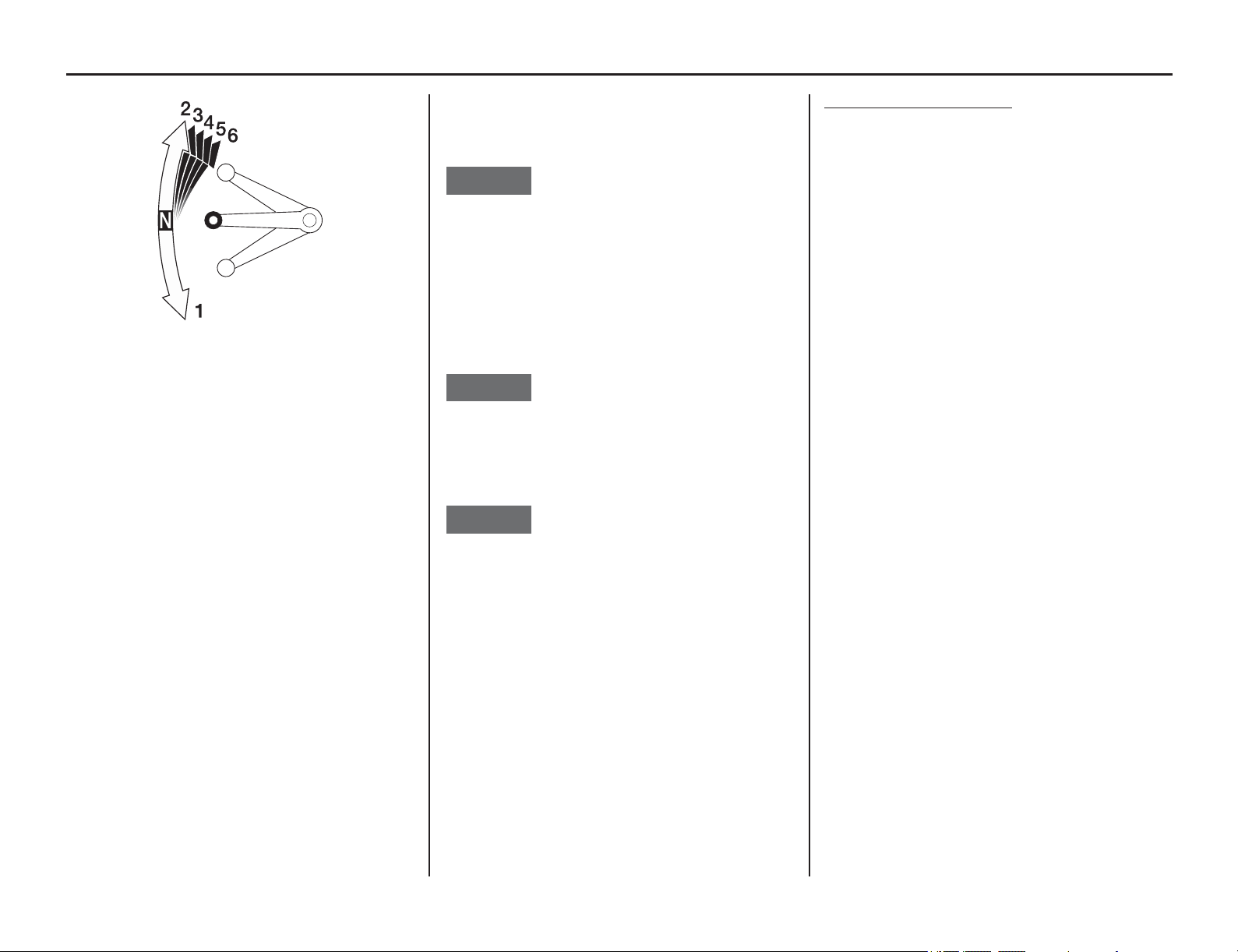
Shifting Gears
Basic Operating Instructions 27
Your motorcycle has 6 forward gears in a one-
down, five-up shift pattern.
To start riding, after the engine has been warmed
and the side stand raised.
1. Close the
throttle and pull the front brake lever
in.
2. Pull the clutch lever all the way in.
3. Depress the shift lever from neutral down to
first gear.
4. Release the front brake lever. Gradually open
the throttle while you slowly release the clutch
lever. If the engine rpm (speed) is too low
when you release the clutch lever, the engine
will stall.
If the engine rpm (speed) is too high or you
release the clutch lever too quickly, your
motorcycle may lurch forward.
5. When you attain a moderate speed, close the
throttle, pull the clutch lever in, and raise the
shift lever. After shifting, release the clutch
lever and apply the throttle.
6. To continue shifting up to each higher gear,
repeat step 5.
7. To shift down to a lower gear, close the
throttle, pull the clutch lever in, and depress the
shift lever. After shifting, release the clutch
lever and apply the throttle.
Remember
to close the throttle and pull the clutch
lever in completely before shifting.
NOTICE
Improper shifting may damage the engine,
transmission, and drive train.
Learning when to shift gears comes with
experience. Upshift to a higher gear or reduce
throttle before engine rpm (speed) gets too high.
Downshift to a lower gear before you feel the
engine laboring (lugging) at low rpm.
NOTICE
Downshifting can help slow your motorcycle,
especially on downhills. However, downshifting
when engine rpm is too high can cause engine
damage.
NOTICE
To prevent transmission damage, do not coast or
tow the motorcycle for long distances with the en-
gine off.
Recommended Shift Points
Ride in the highest gear that lets the engine run and
accelerate smoothly. This will give you good fuel
economy and effective emissions control. When
changing gears under normal conditions, use these
recommended shift points:
Shifting Up:
From 1st to 2nd: 25 mph (40 km/h)
From 2nd to 3rd: 34 mph (55 km/h)
From 3rd to 4th: 50 mph (80 km/h)
From 4th to 5th: 62 mph (100 km/h)
From 5th to 6th: 75 mph (120 km/h)
Shifting Down:
From 6th to 5th: 75 mph (120 km/h)
From 5th to 4th: 62 mph (100 km/h)
From 4th to 3rd: 50 mph (80 km/h)
Pull the clutch lever in when speed drops below 9
mph (15 km/h), when engine roughness is evident,
or when engine stalling is imminent; and shift
down to 1st gear for acceleration.

Braking
28 Basic Operating Instructions
Your motorcycle is equipped with disc braking
systems which are hydraulically activated.
Operating the brake lever applies the front disc
brake. Depressing the brake pedal applies the rear
disc brake.
As a general rule, the front braking system
provides about 70 percent of total stopping power.
For full braking effectiveness, use both the pedal
and lever simultaneously. Using both braking
systems will stop your motorcycle faster with
greater stability.
To slow or stop, apply the brake lever and brake
pedal smoothly, while downshifting to match your
speed.
Gradually increase braking as you feel the brakes
slowing your speed. The increase in engine
compression from downshifting will help slow
your motorcycle.
To prevent stalling the engine, pull the clutch lever
in before coming to a complete stop. For support,
put your left foot down first, then your right foot
when you have finished braking.
Applying the brakes too hard may cause the wheels
to lock and slide, reducing control of your
motorcycle. If this happens, release the brake
controls, steer straight ahead until you regain
control, then reapply the brakes more gently.
When possible, reduce your speed or complete
braking before entering a turn. Avoid braking or
closing the throttle quickly while turning. Either
action may cause one or both wheels to slip and
reduce your control of your motorcycle.
Your ability to brake in a turn and to brake hard in
an emergency situation are important riding skills.
We suggest attending a experienced rider training
course (page 18) to retain these skills.
When riding in wet or rainy conditions, or on loose
surfaces, the ability to maneuver and stop will be
reduced. All of your actions should be smooth
under these conditions. Rapid acceleration,
braking or turning may cause loss of control.
For your safety, exercise extreme caution when
braking, accelerating or turning.
When descending a long, steep grade, use engine
compression braking by downshifting, with
intermittent use of both brakes. Continuous brake
application can overheat the brakes and reduce
their effectiveness.
Riding with your foot resting on the brake pedal or
your hand on the brake lever may actuate the brake
light, giving a false indication to other drivers. It
may also overheat the brakes, reducing
effectiveness.
Parking
Basic Operating Instructions 29
1. Look f
or a level parking area. If you can’t park
on a paved surface, make sure the ground
surface is firm, especially under the side stand.
If you must park on a hill, leave the
transmission in gear and position the rear tire
against the curb at a 45 degree angle.
Make sure flammable materials such as dry grass
or leaves do not come in contact with the exhaust
system when parking your motorcycle. Refer to
Catalytic Converter, page 186.
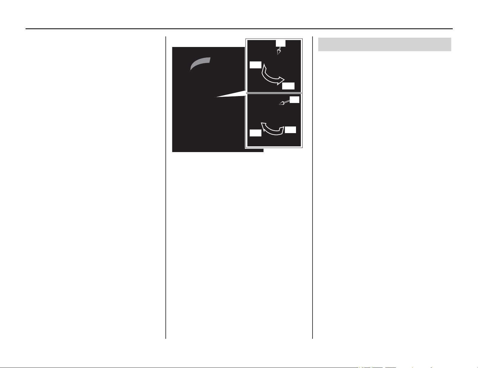
2. Use the side stand to support the motorcycle
while parked.
• To lower the side stand, use your foot to
guide it down. Remember that lowering the
side stand with the transmission in gear will
stop the engine, even if the clutch lever is
pulled in. That is a function of the side stand
ignition cut-off system.
• Check that the side stand is down all the way
so that the side stand ignition cut-off system
(page 25) is activated.
• If you have to park on a soft surface, insert
something solid under the side stand for
support.
3. Use the steering lock, which locks the
handlebar in place. Turn the handlebar all the
way to the left. Push in on the ignition key (1)
and turn it to LOCK. Remove the key.
(To unlock the steering lock, insert the key,
push it in and turn it to the right to the OFF
position.)
•
P
ark your motorcycle in a locked garage
whenever possible. If a garage isn’t available,
park
in a concealed area or in a well-lit area
with
enough pedestrian
traffic to discourage a thief.
• Always take the ignition key with you.
• A
lways use the steering lock, even if you’re
parki
ng for just a minute or two. A thi
ef can
easily
push an unlocked motorcycle to a w
aiting
truck.
•
In addition to the steer
ing lock, use a good
quality anti-theft device made specifically to
lock a motorcycle to a secure object.
• If you decide to use an anti-theft device, select
one of good quality and be sure to follow the
manufacturer’s instructions.
(1) ignition key (A) push in
(B) turn to LOCK
(C) turn to OFF
(1)
(A)
(C)
(A)
(B)
(1)
Theft-prevention Tips

Break-in Guidelines
30 Basic Operating Instructions
Break-in Guidelines
On-Road Use
Help assure your motorcycle’s future reliability
and performance by paying extra attention to how
you ride during the first 300 miles (500 km).
During this period, avoid full-throttle starts and
rapid acceleration.
Off-Road Use
Help assure your motorcycle's future reliability
and performance by paying extra attention to how
you ride during the first operating day or 15 miles
(25 km).
During this period, avoid full-throttle starts and
rapid acceleration.
This same procedure should be followed each time
when:
• piston is replaced
• piston rings are replaced
• cylinder is replaced
• crankshaft or crank bearings are replaced

Servicing Your Honda
Servicing Your Honda 31
Keeping your motorcycle well maintained is
absolutely essential to
your safety. It’s also a good
way to protect your investment, get maximum
performance, avoid breakdowns, and have more
fun.
To help keep your motorcycle in good shape, this
section includes a Maintenance Schedule for
required service, a list of periodic checks you
should perform at least once a month, and step-by-
step instructions for specific maintenance tasks.
You’ll also find important safety precautions,
information on oils, and tips for keeping your
motorcycle looking good.
For information about the exhaust emission and
noise emission requirements of the U.S.
Environmental Protection Agency (EPA), the
California Air Resources Board (CARB), and the
Environment and Climate Change Canada (ECCC)
see page 184.
For information about replacing fuses, see
page 172.
USA only
Maintenance, replacement or repair of the
emission control devices and systems may be
performed by any motorcycle repair
establishment or individual using parts that are
‘‘certified’’ to EPA standards.
An ECM system is used on this motorcycle;
consequently, routine ignition timing adjustment is
unnecessary. If you want to check the ignition
timing, refer to an official Honda Service Manual
(page 194).
An optional tool kit may be available. Check with
your dealer’s parts department.
Before You Service Your Honda
The Importance of Maintenance ......................32
Maintenance Safety..........................................33
Important Safety Precautions.......................33
Periodic Maintenance.......................................34
Maintenance Schedule .....................................35
Maintenance Record (On-Road Use Only)......38
General Competition Maintenance
(Off-Road Use Only) .......................................39
Before & After Competition Maintenance
(Off-Road Use Only) .......................................43
Between Races & Practice Maintenance .....43
After Competition Maintenance ..................44
Service Preparations
Maintenance Component Locations ................45
Seat...................................................................46
Side Cover........................................................47
Fuel Tank .........................................................48
Subframe ..........................................................52
Service Procedures
Fluids & Filters
Fuel System......................................................60
Engine Oil ........................................................69
Coolant.............................................................72
Air Cleaner.......................................................75
Crankcase Breather ..........................................77
Engine
Throttle.............................................................78
Engine Idle Speed ............................................80
Clutch System ..................................................81
Spark Plug........................................................86
Valve Clearance ...............................................87
Piston/Piston Rings/Piston Pin.........................96
Chassis
Suspension..................................................... 105
Front Suspension Inspection ..................... 105
Rear Suspension Inspection....................... 121
Brakes ............................................................ 122
Wheels ........................................................... 126
Tires & Tubes ................................................ 127
Side Stand...................................................... 129
Drive Chain ................................................... 130
Exhaust Pipe/Muffler..................................... 133
Spark Arrester................................................ 135
Additional Maintenance Procedures.............. 136
Electrical
Battery ........................................................... 138
Headlight Aim ............................................... 140
Appearance Care ........................................... 141
The Importance of Maintenance
32 Servicing Your Honda
The Importance of Maintenance
Keeping your motorcycle well-maintained is
absolutely essential to your safety. It’s also a good
way to protect your investment, get maximum
performance, avoid breakdowns, and have more
fun. A properly maintained motorcycle will also
help to reduce air pollution.
Since this motorcycle is capable of being ridden
over rough off-road terrain as well as on pavement,
careful pre-ride inspections and good maintenance
are especially important.
Remember, proper maintenance is your
responsibility. Be sure to inspect your motorcycle
before each ride, perform the periodic checks, and
follow the Maintenance Schedule in this section.
If your motorcycle overturns or is involved in a
crash, be sure your dealer inspects all major parts,
even if you are able to make some of the repairs
yourself.
WARNING
Improperly maintaining this motorcycle or
failing to correct a problem before you ride
can cause a crash in which you can be
seriously hurt or killed.
Always follow the inspection and
maintenance recommendations and
schedules in this owner’s manual.
Maintenance Safety
Servicing Your Honda 33
This section includes
instructions on how to
perform some important maintenance tasks.
Some of the most important safety precautions
follow. However, we cannot warn you of every
conceivable hazard that can arise in performing
maintenance. Only you can decide whether or not
you should perform a given task.
• Make sure the engine is off before you begin
any maintenance or repairs.
This will help eliminate several potential
hazards:
Carbon monoxide poisoning from engine
exhaust. Be sure there is adequate ventilation
whenever you operate the engine.
Burns from hot motorcycle parts. Let the
engine and exhaust system cool before
touching.
Injury from moving parts. Do not run the
engine unless instructed to do so.
• Read the instructions before you begin,
and
make sure you have the tools and skills
required.
• To help prevent the motorcycle from falling
over, park it on a firm, level surface, using the
side stand, an optional workstand or a
maintenance stand to provide support.
• To reduce the possibility of a fire or explosion,
be careful when working around gasoline. Use
only a non-flammable (high flash point)
solvent such as kerosene –not gasoline– to
clean parts. Keep cigarettes, sparks, and flames
away from all fuel-related parts.
Remember that your Honda dealer knows your
motorcycle best and is fully equipped to maintain
and repair it. To ensure the best quality and
reliability, use only new Honda Genuine Parts or
their equivalents for repair and replacement. If you
have the tools and skills required for additional
maintenance jobs, you can purchase an official
Honda Service Manual (page 194).
WARNING
Failure to properly follow maintenance
instructions and precautions can cause
you to be seriously hurt or killed.
Always follow the procedures and
precautions in this owner’s manual.
Important Safety Precautions
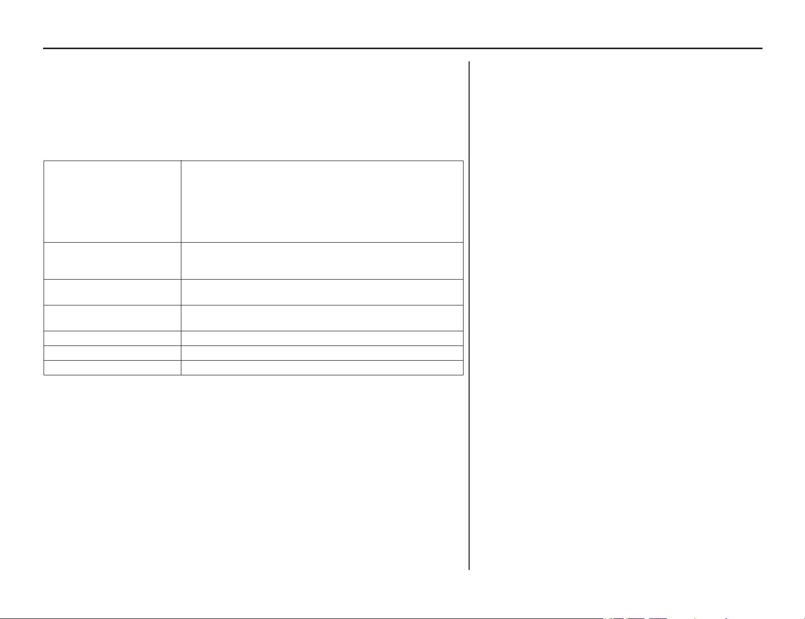
Periodic Maintenance
34 Servicing Your Honda
In addition to the regularly scheduled maintenance (page 35) and daily pre-ride inspection
(page 19),
consider performing the periodic checks on the following page at least once a month,
even if you haven’t ridden your motorcycle, or as often as once a week if you ride frequently
or for long distances. It’s a good idea to perform this maintenance any time you clean your
motorcycle.
Check the odometer reading and perform any scheduled maintenance checks that are needed
(page 35). Remember, more frequent checks may be needed for riding in severe conditions.
Tires & Wheels Check the air pressure with a gauge and add air if needed
(page 127).
Examine the tread for wear (page 127).
Look closely for nails, embedded objects, cuts, and other types of
damage (page 127). Roll your motorcycle so you can inspect the
entire surface.
Check the condition of the rims and spokes.
Fluids Check the levels of the engine oil (page 70), coolant (page 72) and
brake fluid (page 123). Add the correct fluid as necessary, and
investigate the cause of any low fluid level.
Lights Make sure the headlight, position lights, brake light, taillight, and turn
signals are working properly.
Freeplay Check the freeplay of the clutch lever (page 81) and throttle grip
(page 79).
Drive Chain Check condition, adjust slack, and lubricate as needed (page 130).
Fuses Make sure you have a full supply of spare fuses.
Nuts & Bolts Check the major fasteners and tighten as needed.

Maintenance Schedule
(cont’d)
Servicing Your Honda 35
To maintain the safety and reliability of your
motorcycle, regular inspection and service is
required as s
hown in the Maintenance Schedules –
On-Road Use and Off-Road Use – that follow.
The Maintenance Schedule lists items that can be
performed with basic mechanical skills and hand
tools. Procedures for these items are provided in
this manual.
The Maintenance Schedule also includes items that
involve more extensive procedures and may
require special training, tools, and equipment.
Therefore, we recommend that you have your
dealer perform these tasks unless you have
advanced mechanical skills and the required tools.
Procedures for items in this schedule are provided
in an official Honda Service Manual available for
purchase from your dealer (page 194).
Service intervals in the maintenance schedule are
expressed in terms of races and riding hours. To
avoid overlooking required service, we urge you to
develop a convenient way to record the number of
races and/or hours you ride (Off-Road Use only).
If you do not feel capable of performing a given
task or need assistance, remember that your Honda
dealer knows your motorcycle best and is fully
equipped to maintain and repair it. If you decide to
do your own maintenance, use only Honda
Genuine Parts or their equivalents for repair or
replacement to ensure the best quality and
reliability.
Maintenance Schedule
36 Servicing Your Honda
MAINTENANCE SCHEDULE
Perform the Pre-ride Inspection (page 19) at each scheduled maintenance period.
I: Inspect and Clean, Adjust, Lubricate or Replace if necessary. C: Clean. R: Replace. A: Adjust. L: Lubricate.
*Should be serviced by your dealer, unless the owner has proper tools and service data and is mechanically qualified. Refer to the official Honda Service Manual (page 194).
**In the interest of safety, we recommended these items be serviced only by your dealer.
NOTES:1.At higher odometer reading. Repeat at the frequency interval established here.
2.Service more frequently when riding in unusually wet or dusty areas.
3.Service more frequently when riding in rain or at full throttle.
4.Service more frequently when riding OFF-ROAD.
5.USA only.
6.Replacement requires mechanical skill.
FREQUENCY WHICHEVER COMES
FIRST
INITIAL
MAINTENANCE
REGULAR MAINTENANCE INTERVAL (NOTE 1)
Regular
Replace
Refer to Page:
mi 100 600 1200 1800 2400 3000 3600 20000
Km 150 1000 2000 3000 4000 5000 6000 32000
ITEMS NOTE MONTH 1 4 8 12 16 20 24
* FUEL LINE II 61
** FUEL FILTER R R 63 – 67
* THROTTLE OPERATION II 79
* AIR CLEANER (NOTE 2) C C C C C C 3 years 75, 76
CRANKCASE BREATHER (NOTE 3) IIIIII 77
SPARK PLUG II 86
* VALVE CLEARANCE I I 87 – 95
ENGINE OIL RRRRRR 70, 71
ENGINE OIL FILTER RRRRRR 70, 71
* DECOMPRESSOR SYSTEM II 92
** ENGINE IDLE SPEED I IIIIII 80
** INTAKE/EXHAUST VALVE R–
** PISTON AND PISTON RINGS R 98 – 100
** PISTON PIN R 98 – 100
** CRANKSHAFT R–
** CRANKSHAFT BEARING R–
** TRANSMISSION I–
** CAM CHAIN TENSIONER LIFTER R–
RADIATOR COOLANT (NOTE 6) I I 3 years 72, 74
* COOLING SYSTEM I IIIIII 73
* SECONDARY AIR SUPPLY SYSTEM II –
* EVAPORATIVE EMISSION CONTROL SYSTEM (NOTE 3) I–
DRIVE CHAIN (NOTE 4) I, L (I, L: every 300 mi (500 km) or 3 months) 130 – 132
DRIVE CHAIN SLIDER IIIIII 130
BRAKE FLUID (NOTE 6) IIIIIR 2 years123, 124
BRAKE PADS WEAR IIIIII 125
BRAKE SYSTEM I IIIIII 122
BRAKE LIGHT SWITCH IIIIII 125
* HEADLIGHT AIM II 140
CLUTCH SYSTEM I I I 81 – 82
SIDE STAND II 129
* SUSPENSION I I 144, 146
* SPARK ARRESTER (NOTE 5) (C: every 1,000 mi (1,600 km) or every 100 operating hours) 135
* NUTS,
BOLTS, FASTENERS (NOTE 4) I I I 137, 181 – 183
**
WHEELS/TIRES (NOTE 4) I IIIIII 126 – 128
** STEE
RING HEAD
BEARINGS I I I 136
Maintenance Schedule
Servicing Your Honda 37
MAINTENANCE SCHEDULE – OFF-ROAD USE
All items should be checked before each off-road event. See your dealer unless you are mechanically qualified and have the proper tools.
Damage from Off-Road use is not covered by the Distributor’s Limited Warranty on your Honda.
Perform the Pre-ride Inspection (page 19) at each scheduled maintenance period.
I: Inspect and Clean, Adjust, Lubricate or Replace if necessary. C: Clean. R: Replace. A: Adjust. L: Lubricate.
WE RECOMMEND THESE ITEMS BE SERVICED BY REFERRING TO AN OFFICIAL HONDA SERVICE MANUAL.
This maintenance schedule is based upon average riding condition. Machine subjected to severe use require more frequent servicing.
NOTES:1.Clean after every moto for dusty riding condition.
2.Replace every 2 years. Replacement requires mechanical skill.
3.Replace after the first break-in ride.
4.Inspect after the first break-in ride.
5.Replace the engine oil, if the clutch discs and plates are replaced.
6.Replace every year.
FREQUENCY
ITEMS
NOTE
Each race or
about 3.5 hours
Every 4 races or
about 15.0 hours
Every 8 races or
about 30.0 hours
Refer to Page:
FUEL LINE (NOTE 6) I R 61
FUEL PUMP FILTER (NOTE 6) R 63 – 67
THROTTLE OPERATION I 79
AIR FILTER (NOTE 1) C 75, 76
CRANKCASE BREATHER I 77
SPARK PLUG I 86
VALVE CLEARANCE/DECOMPRESSOR SYSTEM (NOTE 4) I 87 – 95
ENGINE OIL
(NOTE 3)
(NOTE 5)
IR70, 71
ENGINE OIL FILTER (NOTE 3) R 70, 71
ENGINE IDLE SPEED I 80
PISTON AND PISTON RINGS R 98 – 100
PISTON PIN R 98 – 100
RADIATOR COOLANT (NOTE 2) I 72, 74
COOLING SYSTEM I 73
DRIVE CHAIN I, L R 130 – 132
DRIVE CHAIN SLIDER I 130
DRIVE CHAIN ROLLER I 131
DRIVE SPROCKET I 132
DRIVEN SPROCKET I 132
BRAKE FLUID (NOTE 2) I 123, 124
BRAKE PADS WEAR I 125
BRAKE SYSTEM I 122
CLUTCH SYSTEM (NOTE 5) I 81 – 85
CONTROL CABLES I, L 136
EXHAUST PIPE/MUFFLER I 133 – 135
SUSPENSION I 105, 121
SWINGARM/SHOCK LINKAGE L 42, 121
FORK OIL (NOTE 3) R 108, 109, 115 – 121
NUTS, BOLTS, FASTENERS I 137, 181 – 183
WHEELS/TIRES I
126 – 128
STEERING HEAD BEARINGS I 136
SIDE STAND I 129
Maintenance Record (On-Road Use Only)
38 Servicing Your Honda
Keeping an accurate maintenance record will help ensure that your motor
cycle is properly maintained. Retain detailed receipts to verify the maintenance was
performed. If the motorcycle is sold, these receipts should be transferred with the motorcycle to the new owner. Make sure whoever performs the maintenance
completes this record. All scheduled maintenance, including the 100 mile (150 km) or 1 month initial maintenance, is considered a normal owner operating cost
and will be charged for by your dealer. Use the space under Notes to record anything you want to remind yourself about or mention to your dealer.
Miles (km) or Month Odometer Date Performed By: Notes
100 (150) or 1
600 (1,000) or 4
1,200 (2,000) or 8
1,800 (3,000) or 12
2,400 (4,000) or 16
3,000 (5,000) or 20
3,600 (6,000) or 24
4,200 (7,000) or 28
4,800 (8,000) or 32
5,400 (9,000) or 36
6,000 (10,000) or 40
6,600 (11,000) or 44
7,200 (12,000) or 48
7,800 (13,000) or 52

General Competition Maintenance (Off-Road Use Only)
Servicing Your Honda 39
Perform m
aintenance on firm, level ground using
the side stand, an optional workstand, or
equivalent support.
When tightening bolts, nuts or screws, start with
the larger diameter or inner fasteners, and tighten
them to the specified torque using a crisscross
pattern.
Use Honda Genuine Parts or their equivalents
when servicing your motorcycle.
Clean parts in non-flammable (high flash point)
cleaning solvent (such as kerosene) when
disassembling. Lubricate any sliding surfaces,
O-rings, and seals before reassembling. Grease
parts by coating or filling where specified.
After any engine disassembly, always install new
gaskets, O-rings, cotter pins, piston pin clips, snap
rings, etc. when reassembling. After reassembly,
check all parts for proper installation and
operation.
All Pre-ride Inspection Items
Refer to Pre-ride Inspection on page 19.
General Competition Maintenance (Off-Road Use Only)
40 Servicing Your Honda
Spark Plug
Some non-resistor plugs may cause ignition problems.
Refer to the recommendations elsewhere in this manual for
specific types so you will be sure to use the proper reach and
heat range. Replace periodically as specified in the
Maintenance Schedule (pages 36, 37).
Spark Plug Cap
Install a small plastic wire band around the spark plug cap to
reduce any possibility of it loosening or of water penetration.
Air Cleaner
Clean and oil your air cleaner regularly because the volume
of air able to pass through it has a great effect on
performance. Both engine performance and long term
durability may be affected by an air cleaner that has
deteriorated and allows dirt to pass. Inspect the air cleaner
closely each time it’s serviced for evidence of small tears or
seam separation. Keep a spare air cleaner oiled and ready to
install, sealed in a plastic bag. Riding in dusty conditions
may require servicing the air cleaner or replacing it with a
pre-serviced air cleaner between races. Be careful not to over
oil the air cleaner. While it is important to oil the air cleaner
thoroughly, over oiling will cause an overall rich running
condition, probably more noticeable off idle and in low rpm
performance. Follow the servicing instructions in the
Maintenance section. Use Pro Honda Foam Air Filter Oil or
an equivalent. Be sure to grease the air cleaner flange where
it contacts the air cleaner housing. Pro Honda Foam Air Filter
Sealer or an equivalent is handy for this because any dirt that
penetrates this sealing area will show up clearly (page 75).
Use the Honda Genuine air cleaner or an equivalent air
cleaner specified for your model.
Using the wrong Honda air cleaner or a non-Honda air
cleaner which is not of equivalent quality may cause
premature engine wear or performance problems.
Engine Oil and Filter
Drain and replace engine oil often to ensure the greatest
service life of the piston, cylinder, crankshaft, transmission
and clutch.
Also replace engine oil filter often to ensure the greatest
service life. Frequent changes will also assure consistent
performance of power, response, both shifting and clutch
action (page 70).
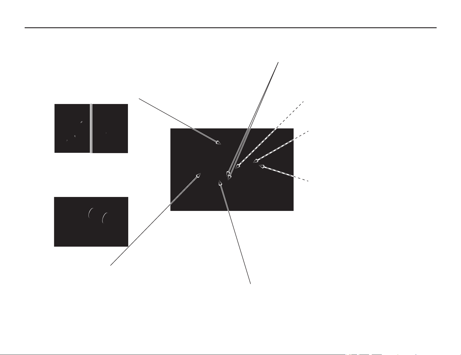
General Competition Maintenance (Off-Road Use Only)
Servicing Your Honda 41
Handgrips
Always use Honda Bond A, Pro Honda Handgrip Cement
(U.S.A. only) when replacing handgrips.
Refer to an official Honda Service Manual (page 194) for
installation instructions.
Throttle Grip/Handlebar Grip
Right throttle grip: Align the index mark on the throttle grip
with the index mark of the throttle pipe.
Left handlebar grip: Align the index mark on the left
handlebar grip with the paint mark on the handlebar.
Gaskets
Always use new gaskets when reassembling components.
Fuel Line
Refer to Fuel Line Inspection on page 61.
Check the fuel line for deterioration, damage, or leakage.
Replace the fuel line every year.
For added security, you may choose to bind the handgrips to
the handlebar and throttle pipe with safety wires to prevent the
possibility of them loosening. Position the twisted wire ends
away from your palms and be sure to bend the wire ends well
into the handgrip rubber so they will not snag your glove.
Engine Mounting Bolts and Nuts
Make sure the engine mounting bolts and nuts are tightened
to the proper torque specification.
Frame
Because your motorcycle is a high-performance machine, the frame
should not be overlooked as part of your overall off-road use
maintenance program. Periodically inspect the frame closely for
possible cracking or other damage. It makes good racing sense.
Cylinder head/Cylinder
Put a little grease on the dowel pins of the cylinder head and cylinder to
prevent corrosion from dissimilar metals. The tolerances are quite tight, so
it’s important to keep these dowels absolutely clean (pages 96, 98).
Electrical Connectors
Clean electrical connectors and wrap them with electrical
tape to reduce the possibility of unwanted disconnections,
water shorts or corrosion.
Fuse
Check the fuse before looking elsewhere for the cause of an
electrical problem.
Battery
The start button uses current from the battery.
Limited operation also allows the battery to discharge. If
you do not ride frequently, we recommend that you charge
the battery frequently (see Battery Charging on page 139).
If you do not expect to ride your motorcycle for at least 2
weeks, we recommend you remove the battery – or at least
disconnect the battery cables (negative cable first).
Fork Oil/Performance
Disassemble, clean and inspect the fork and replace the oil
regularly. Contamination due to the tiny metal particles produced
from the normal action of the fork, as well as normal oil
breakdown, will deteriorate the performance of the suspension.
Refer to an official Honda Service Manual (page 194). Use only
Pro Honda HP Fork Oil, SS-19 or an equivalent which contains
special additives to assure maximum performance of your
motorcycle's front suspension.
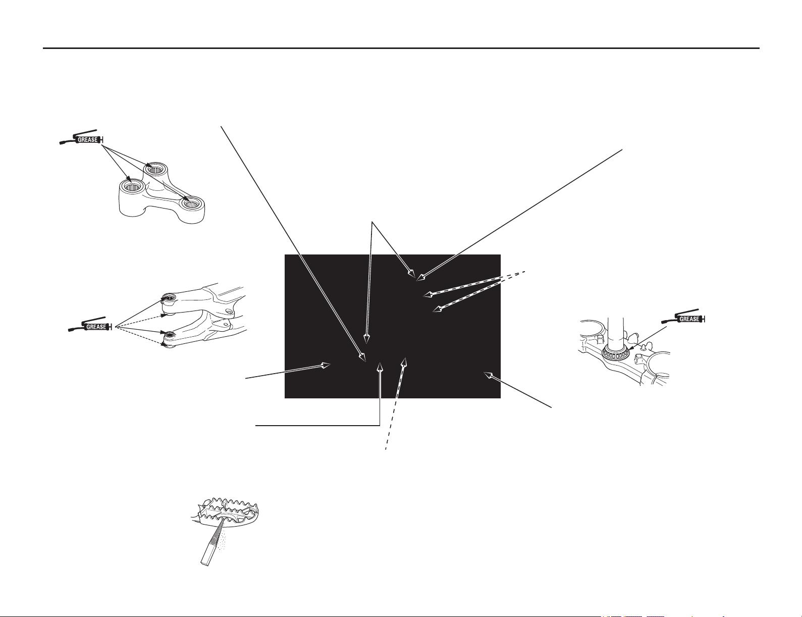
General Competition Maintenance (Off-Road Use Only)
42 Servicing Your Honda
Brake Fluid Replacement
Refer to Brake Pad Wear on page 125.
Brake Caliper Inspection: Be sure both the front and rear
calipers are able to move freely on the caliper pin and caliper
bracket pins. Check pad thickness periodically and replace the
pads when minimum thickness is reached. If the brakes fade
when they are hot, inspect the pads for glazing or damage, and
replace if necessary.
Brake Fluid Replacement: Refer to an official Honda Service
Manual (page 194) for brake fluid replacement instructions.
Replace the brake fluid in the brake system every 2 years.
Replace the fluid more frequently if you subject your brakes to
severe use. Heavy braking heats the brake fluid and it may
deteriorate sooner than expected. Any type of riding, that
requires frequent use of the brakes, such as in tight woods, can
shorten the service life of brake fluid.
Spokes
Check spoke tension frequently between the first few rides.
As the spokes, spoke nuts and rim contact points seat-in,
the spokes may need to be retightened. Once past this initial
seating-in period, the spokes should hold their tension.
Still, be sure your race maintenance program includes
checking spoke tension and overall wheel condition on a
regular basis (page 126).
Nuts, Bolts, Etc.
Application of a thread locking agent to essential fasteners
offers added assurance and security. Remove the nuts,
clean the threads of both the nuts and bolts, apply Pro
Honda Hondalock or an equivalent and tighten to the
specified torque.
Bleed Hole
After every races, check the bleed hole below the water pump
cover for leakage. Clean away any clogged dirt or sand, if
necessary. Check for signs of seal leakage. If water leaks
through the bleed hole, replace the mechanical seal. If oil leaks
through the bleed hole, replace the oil seal. Make sure that
there is no continuous coolant leakage from the bleed hole
while operating the engine. A small amount of coolant
weeping from the bleed hole is normal. See an official Honda
Service Manual or consult your dealer for replacing the
mechanical seal or oil seal. Both seals should be replaced at
the same time.
Suspension Linkage Lubrication
Disassemble, clean, inspect and lubricate all suspension linkage
pivot bearings with molybdenum disulfide grease (containing
more than 3% molybdenum disulfide additive Moly Paste 77)
after each 15.0 hours of running time in order to maintain proper
suspension performance and minimize component wear.
Steering Head Bearings
Periodically clean, inspect and regrease the steering head
bearings — especially if wet, muddy or extremely dusty courses
are encountered often.
Use urea based multi-purpose grease designed for high
temperature, high pressure performance (example: EXCELITE
EP2 manufactured by KYODO YUSHI, Japan or equivalent).
Footpegs
Worn footpeg teeth can be repaired by filing the grooves
between the teeth with a triangular shaped file.
Be aware that filing them too sharp will reduce boot sole
lifespan. Sharpen only the points of the teeth. Filing the
grooves deeper will weaken the footpegs. Be sure the pegs
are free to pivot freely and that the pivot pin retaining cotter
pins are in good condition.
Swingarm
Do not attempt to weld or otherwise repair a damaged
swingarm. Welding will weaken the swingarm.
Swingarm Pivot Lubrication
Clean, inspect and lubricate the swingarm and suspension
linkage pivots with molybdenum disulfide grease (containing
more than 3% molybdenum disulfide additive Moly Paste 77).
Be sure all of the dust seals are in good condition.
Throttle Control
Remove the throttle control every few rides, clean the
inside of the throttle pipe and handlebar thoroughly.
Inspect the cable carefully for kinks or other damage that
may restrict throttle control in anyway. Move the
handlebar from lock to lock to be sure there is no cable
interference. Make certain the throttle operation is
perfect after servicing and inspecting.
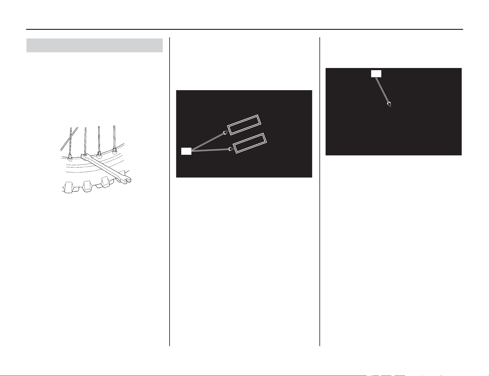
Before & After Competition Maintenance (Off-Road Use Only)
Servicing Your Honda 43
After practice or between races you have a chance
to make additional checks and adjustments.
• Clean accumulated dirt from under the fenders
and off the wheels, suspension components,
handgrips, controls, and footpegs. A stiff,
nylon parts cleaning brush works well.
• Check tire air pressure.
• Check spoke tension.
• Check to make sure the sprocket bolts and nuts
are secure.
• Clean the sides of the drive chain with a stiff,
nylon parts-cleaning brush. Lubricate and
adjust the chain as necessary.
Do not perform maintenance while engine is
running. Injury to your fingers or hands may result.
• After adjustment, check that the chain adjuster
index marks (1) are in the same position on
each side. This will ensure that the rear wheel
is in proper alignment and allow maximum
performance from the rear disc brake.
Maintaining proper wheel alignment will also
extend brake pad wear.
• Suspend the front wheel above the ground and
use the pressure release screws (2) to release
the built-up pressure in the forks. This pressure
is caused by normal fork action while riding.
Between Races & Practice Maintenance
(1) chain adjuster index marks
(1)
(2) pressure release screw
(2)
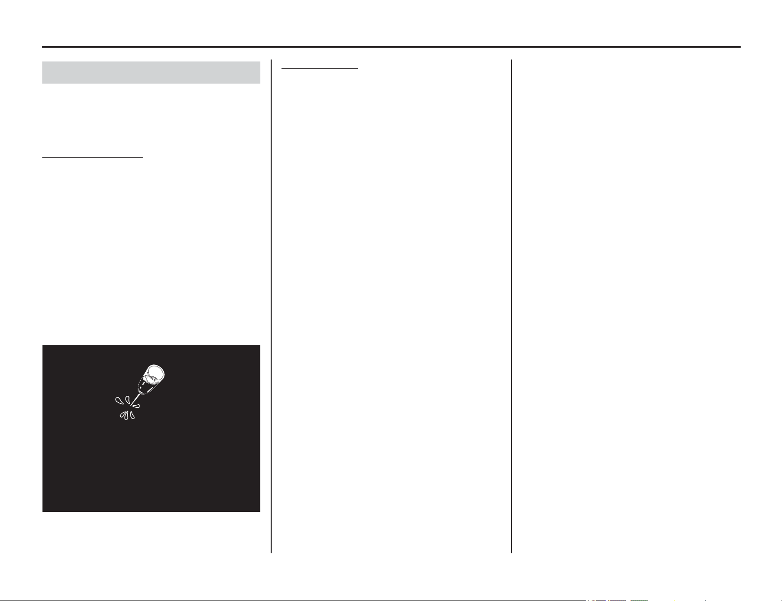
44 Servicing Your Honda
Before & After Competition Maintenance (Off-Road Use Only)
It is important to the long term performance of
your motorcycle to practice a consistent
maintenance program. Right after the event is a
good time to begin your next maintenance cycle.
After Race
Lubrication
Apply a light coating of rust-inhibiting oil to the
drive sprocket and any steel portions of the chassis
or engine where the paint has worn away.
This will prevent rusting of the exposed metal.
Apply rust-inhibiting oil more heavily if the event
was particularly wet or muddy. Take care to avoid
spraying any oil near the brake pads or the brake
discs.
Take care to prevent catching your fingers between
the chain and sprocket.
Remove the drive chain, clean and lubricate it
(pages 131, 132). Be sure the chain is wiped clean
and is dry before lubricating the chain.
Routine Cleaning
If your motorcycle is only slightly dirty, it is best
to clean it by hand with the aid of a stiff bristled
nylon brush and some clean rags.
Take care to prevent catching your fingers between
the chain and sprocket.
A variety of reasonably priced cleaning brushes
are available from variety, drug, food, and
hardware stores. Some of these brushes are
extremely useful in removing dirt from the many
tight contours of the metal pieces of your
motorcycle. Avoid using stiff, abrasive brushes on
the plastic or rubber parts.
If your motorcycle was exposed to sea air or salt
water, rinse it as soon as possible after the event,
dry it, and apply a spray lubricant to all metal parts.
If you decide to wash your motorcycle or use
cleaners, refer to Appearance Care (page 141).
After Competition Maintenance
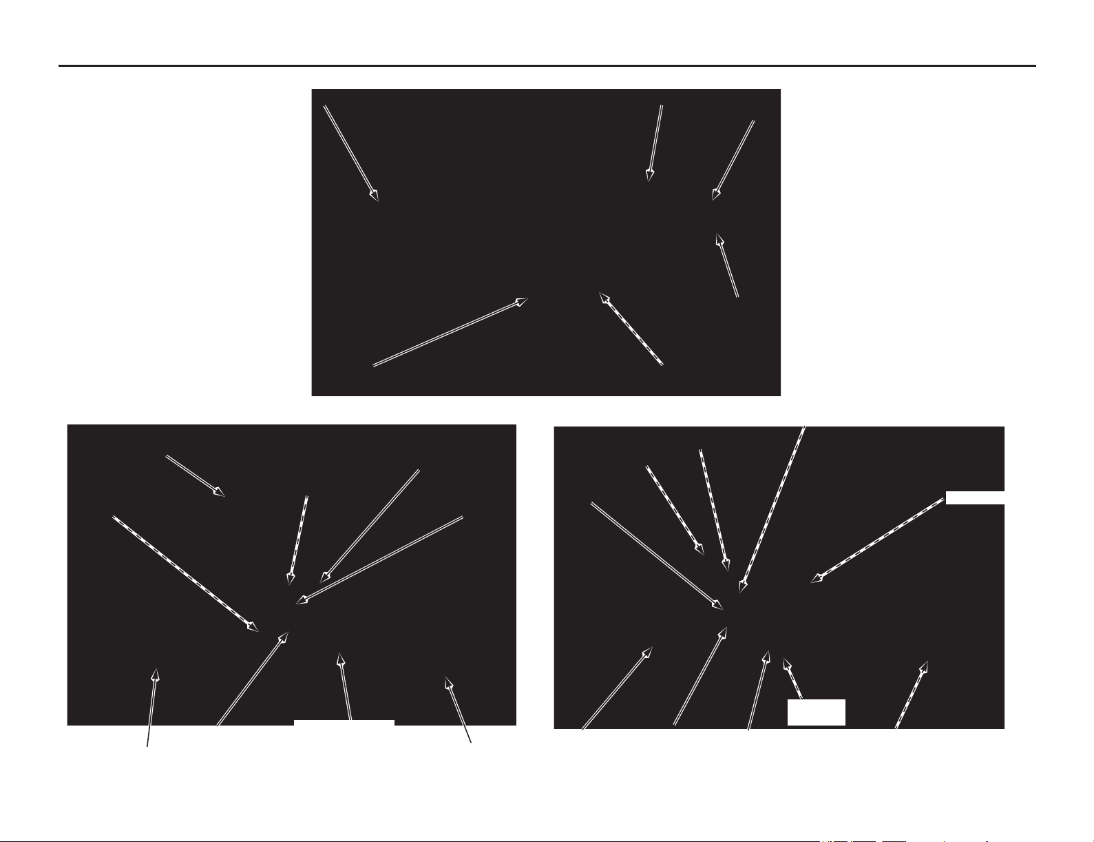
Maintenance Component Locations
Servicing Your Honda 45
clutch lever
front brake fluid reservoir
throttle grip
radiator cap
fuel fill cap
front brake lever
• rear suspension high speed
compression damping adjuster
• rear suspension low speed
compression damping adjuster
front suspension
compression damping
adjuster (both left and
right)
fast idle knob
(engine idle speed)
engine oil filter
drive chain
front brake caliper
engine oil fill cap
rear suspension
rebound damping
adjuster
crankcase
breather tube
air cleaner
rear suspension spring pre-load adjuster
spark plug
engine oil
drain bolt
rear brake
pedal
rear brake fluid
reservoir
rear brake
caliper
battery
front suspension rebound damping
adjuster (both left and right)
crankcase
breather tube
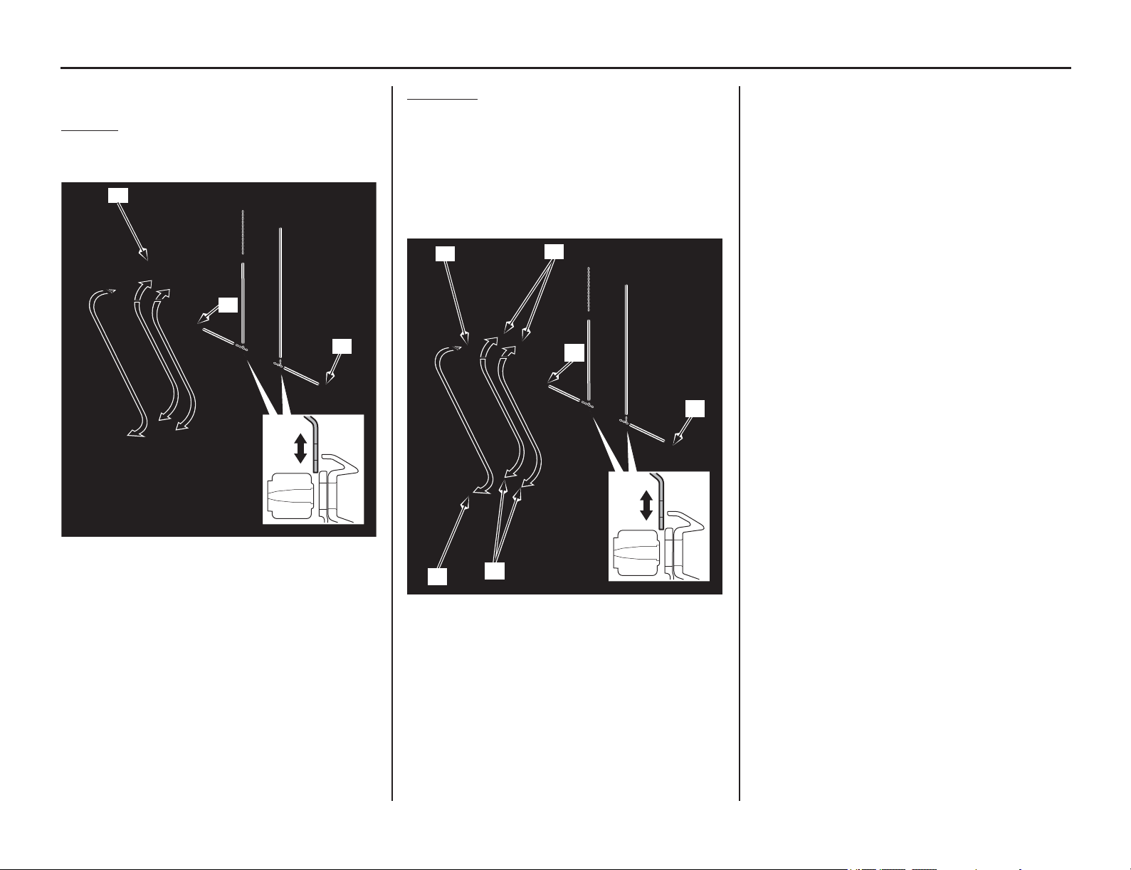
Seat
46 Servicing Your Honda
Refer to Important Safety Precautions on page 33.
Rem
oval
1. Remove the seat mounting bolts (1).
2. Remove the seat (2) by pulling it backward.
Installation
1. Install the seat while aligning the seat front
prong (1) with the slot (2) of the fuel tank and
seat center prongs (3) with the seat support
base slots (4).
2. Install and tighten the seat mounting bolts (5)
to the specified torque:
19 lbf·ft (26 N·m, 2.7 kgf·m)
(1) seat mounting bolts (2) seat
(1)
(2)
(1)
(1) seat front prong (4) seat support base slots
(2) slot (5) seat mounting bolts
(3) seat center prongs
(1)
(3)
(5)
(4)
(2)
(5)
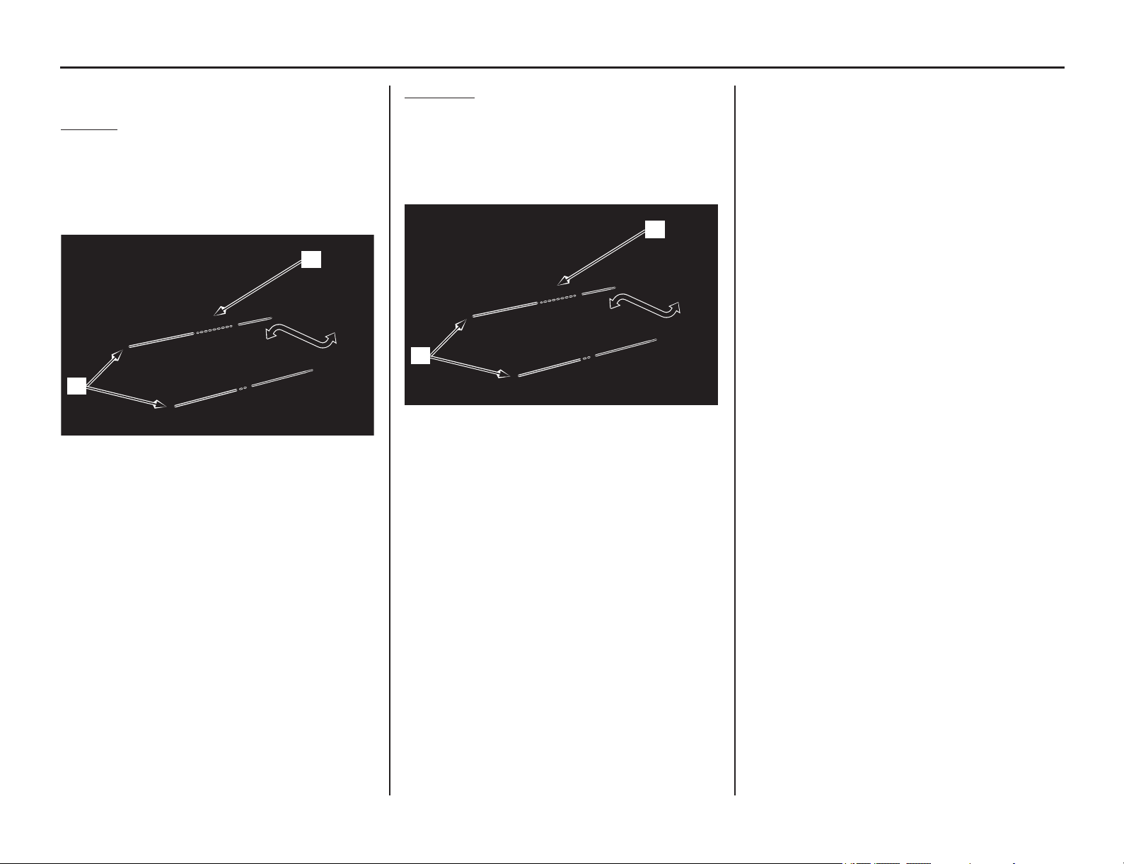
Side Cover
Servicing Your Honda 47
Refer to Important Safety Precautions on page 33.
Rem
oval
1. Remove the seat (page 46).
2. Remove the side cover (1) by removing the
bolts (2).
The right and left side covers can be removed in
the same manner.
Installation
1. Install the side cover (1), and then tighten the
bolts (2) to the specified torque:
7 lbf·ft (10 N·m, 1.0 kgf·m)
The right and left side covers can be installed in the
same manner.
2. Install the seat (page 46).
(1) side cover
(2) bolts
(1)
(2)
(1) side cover
(2) bolts
(1)
(2)
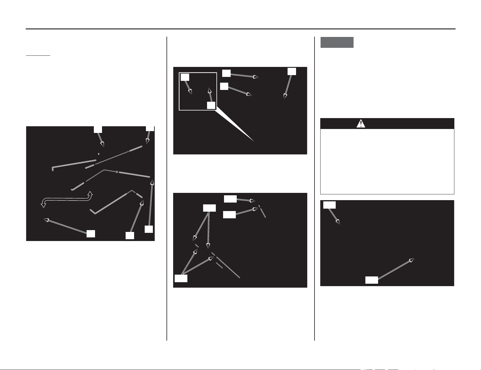
Fuel Tank
48 Servicing Your Honda
Fuel Tank
Refer to Important Safety Precautions on page 33.
Removal
1. Remove the seat (page 46).
2. Remove the shroud A bolt (1), shroud B bolt
(2) and shroud C bolt (3).
3. Slide the shroud (4) toward the up to separate
them from the side cover (5), and then remove
the shroud.
The right and left shrouds can be removed in the
same manner.
4. Release the breather tube (6) from the tube
guide (7) on the top shelter (8).
5. Disconnect the breather tube (6) at the tube
joint (9).
6. Remove the fuel tank bolts (10) and washers
(11).
7. Lift the fuel tank (12) out of the frame to the
left of the frame.
Do not support the fuel tank by the fuel feed hose
(13).
NOTICE
The fuel tank is made of titanium material. Since
the fuel tank has not been painted, it might be
discolored with mud and dust.
To remove mud or dust, use a sponge or soft cloth
and a stainless steel kitchen detergent, then rinse
well clean water.
After washing, rinse with plenty of water and dry
with a clean cloth.
(1) shroud A bolt
(2) shroud B bolt
(3) shroud C bolt
(4) shroud
(5) side cover
(4)
(5)
(2)
(1)
(3)
(6) breather tube (8) top shelter
(7) tube guide (9) tube joint
(10) fuel tank bolts (11) washers
(7)
(6)
(8)
(9)
(6)
(11)
(10)
(10)
(11)
WARNING
Gasoline is highly flammable and
explosive.
You can be burned or seriously injured
when handling fuel.
• Stop the engine and keep heat, sparks
and flame away.
• Handle fuel only outdoors.
• Wipe up spills immediately.
(12) fuel tank
(13) fuel feed hose
(12)
(13)
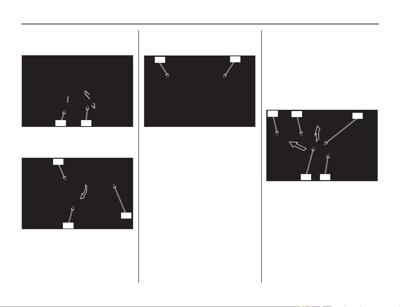
Fuel Tank
(cont’d)
Servicing Your Honda 49
8. Disconnect the fuel pump connector (14) and
remove the harness band clip (15).
9. Reposition the fuel tank and start the engine
and let it idle until the engine stalls.
10. Lift the fuel tank (12) out of the frame.
Remove the fuel quick connect fitting cover
(16) from the fuel pump (17).
11. Check the fuel quick connect fitting (18) for
dirt, and clean if necessary.
12.
Place a shop towel (19) over the fuel quick
connect fitting.
13. Unlock the slide retainer (20) of the quick
connect fitting by completely pulling it up.
Release the fuel quick connect fitting (18)
from the fuel joint (21) while holding the
connector housing (22), then remove the fuel
tank (12).
Use a
shop towel to absorb the remaining fuel
in the fuel feed hose.
• Be careful not to damage the hose or other
parts.
• Do not use tools.
• Dirt intruding into the connector housing
may cause slide retainer sticking.
(14) fuel pump connector (15) harness band clip
(12) fuel tank
(16) fuel quick connect fitting cover
(17) fuel pump
(15)(14)
(17)
(16)
(12)
(18) fuel quick connect fitting (19) shop towel
(19)
(18)
(12) fuel tank (21) fuel joint
(18) fuel quick connect fitting (22) connector housing
(20) slide retainer
(22)
(20)
(12)
(21)
(18)
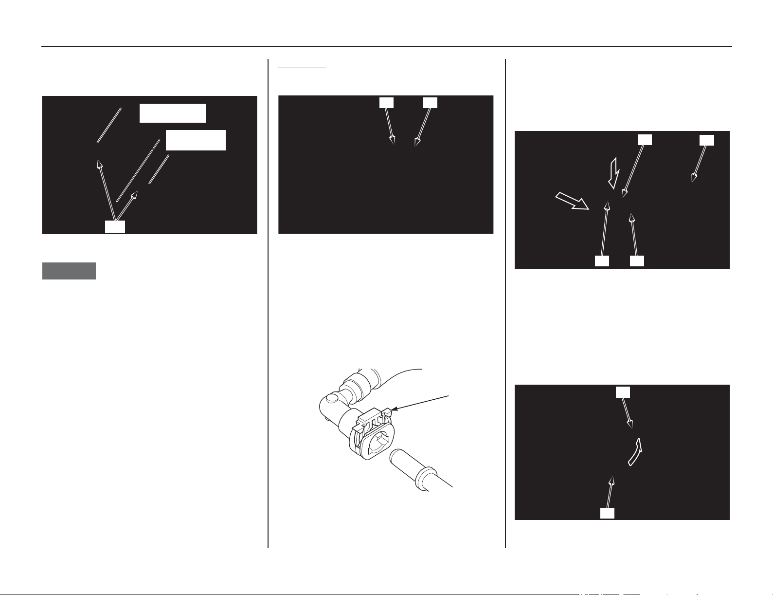
50 Servicing Your Honda
Fuel Tank
14. Check for interference between the frame and
tank, and adjust the cushion rubbers (23) on the
both sides of the frame if necessary.
NOTICE
Do not ride your motorcycle in state which the
cushion rubbers have been removed.
It may cause the fuel tank cracking.
Installation
1. Make sure the rubber cover (1) is onto the fuel
joint (2) of the fuel pump as shown.
2. Be sure that the slide retainer (3) is completely
pulled up before connecting the quick connect
fitting.
• Do not bend or twist the fuel feed hose.
• Do not reuse the kinked or damaged fuel
hose.
• Do not use gloves or a shop towel while
installing the quick connect fitting.
3. Place the fuel tank (4) onto the frame.
4. Connect the quick connect fitting to the fuel
joint (2) until you hear the “click” while
holding the connector housing (5).
If it is hard to connect, put a small amount of
engine oil on the pipe end of the fuel joint.
5. Make sure the connection is secure and that the
slide retainer is firmly locked into place; check
visually and by pulling the connector housing.
6. Install the fuel quick connect fitting cover (6).
Be sure the rubber cover (1) is properly
installed between the fuel quick connect fitting
cover and fuel pump.
(23) cushion rubbers
3.35 ± 0.10 in
(85.0 ± 2.5 mm)
(23)
1.10 ± 0.10 in
(28.0 ± 2.5 mm)
(1) rubber cover
(2) fuel joint
(3) slide retainer
(1) (2)
(3)
(2) fuel joint (4) fuel tank
(3) slide retainer (5) connector housing
(1) rubber cover
(6) fuel quick connect fitting cover
(3)
(4)
(2)
(5)
(1)
(6)
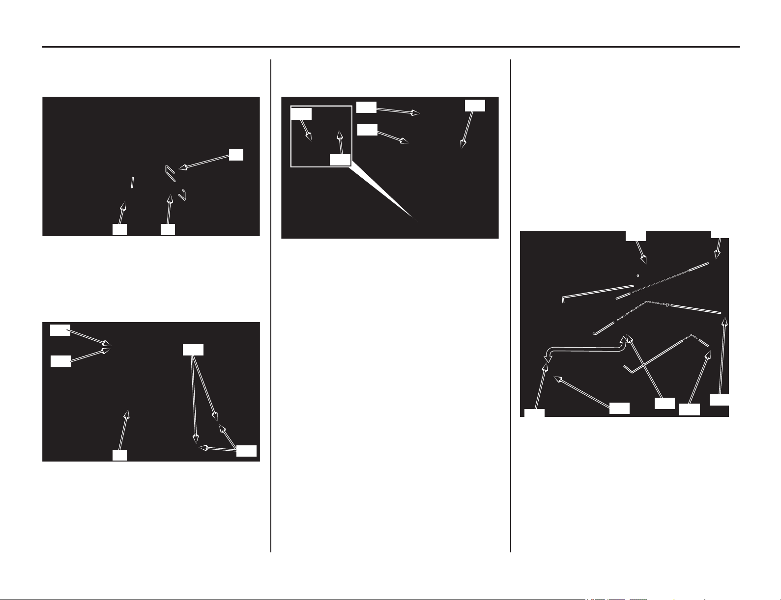
Servicing Your Honda 51
Fuel Tank
7. Install the harness band clip (7) to the stopper
cable guide (8).
Connect the fuel pump connector (9).
8. Install the fuel tank (4) into the frame. Install
the washers (10) and fuel tank bolts (11), then
tighten the bolts to the specified torque:
7 lbf·ft (10 N·m, 1.0 kgf·m)
9. Connect the breather tube (12) to the tube joint
(13). Install the breather tube to the tube guide
(14) onto the top shelter (15).
10. Slide the shroud (16) toward the down so that
the shroud tab (17) and the slot (18) on the side
cover (19) is aligned.
11. Install the shroud C bolt (20), B bolt (21) and
shroud A bolt (22).
Tighten the shroud A and B bolts to the
specified torque:
7 lbf·ft (10 N·m, 1.0 kgf·m)
Tighten the shroud C bolt to the specified
torque:
3.8 lbf·ft (5.2 N·m, 0.5 kgf·m)
The right and left shrounds can be installed in
the same manner.
12. Install the seat (page 46).
(7) harness band clip (9) fuel pump connector
(8) stopper cable guide
(4) fuel tank (11) fuel tank bolts
(10) washers
(7)(9)
(8)
(4)
(11)
(10)
(11)
(10)
(12) breather tube (14) tube guide
(13) tube joint (15) top shelter
(13)
(12)
(12)
(15)
(14)
(16) shroud (20) shroud C bolt
(17) tab (21) shroud B bolt
(18) slot (22) shroud A bolt
(19) side cover
(16)
(20)
(21)
(22)
(17)
(19)
(18)
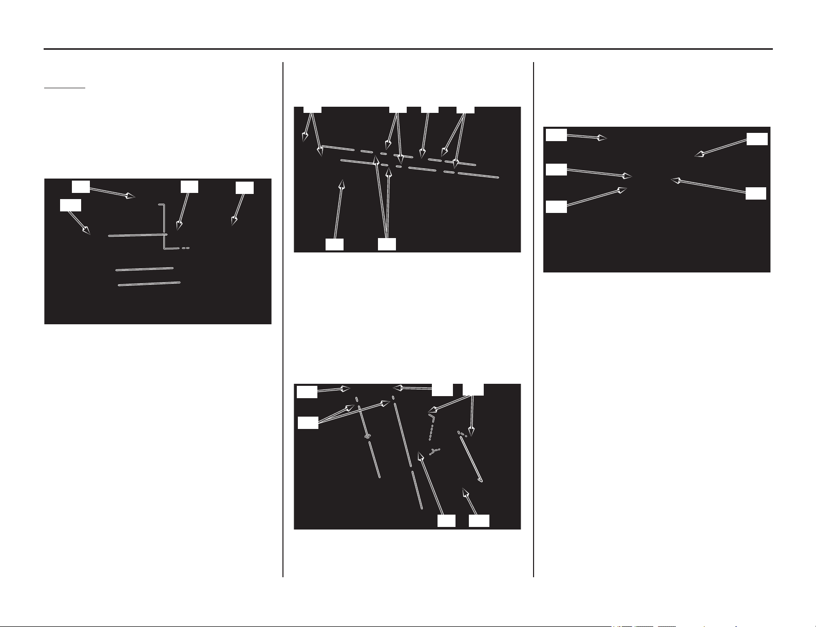
Subframe
52 Servicing Your Honda
Subframe
Refer to Important Safety Precautions on page 33.
Removal
1. Remove the battery (page 138).
2. Remove the fuel tank (page 48).
3. Remove the muffler (page 133).
4. Remove the left side cover (page 47).
5. Remove the ECM (1) from the ECM stay (2).
6. Remove the starter relay (3) from the seat
support base (4).
7. Remove the stay mounting bolts (5), ECM stay
(2), collars A (6), collars B (7), bank angle
sensor assembly (8) and washers (9).
8. Remove the seat support base mounting bolts
(10) and collars (11). Release the hooks (12)
from
the seat
rail, then remove the seat support
base (4) from the subframe (13).
9. Disconnect the IAT sensor connector (14).
Disconnect the crankcase breather tube (15)
and air injection air tube (16) from the air
cleaner housing (17).
Loosen the connecting tube band screw (18).
(1) ECM
(2) ECM stay
(3) starter relay
(4) seat support base
(2)
(1)
(3)
(4)
(2) ECM stay
(5) stay mounting bolts
(6) collars A
(7) collars B
(8) bank angle sensor assembly
(9) washers
(4) seat support base (12) hooks
(10) bolts (13) subframe
(11) collars
(5) (7)
(6)
(2)
(8)
(9)
(4) (13)
(10)
(11)
(12)
(10)
(14) IAT sensor connector
(15) crankcase breather tube
(16) air injection air tube
(17) air cleaner housing
(18) connecting tube band screw
(17)
(18)
(14)
(15)
(16)
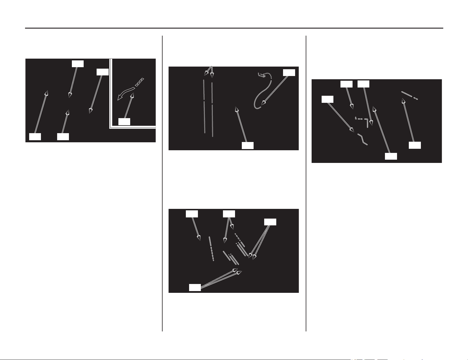
Subframe
(cont’d)
Servicing Your Honda 53
10. Remove the negative (-) battery cable bands
(19), then remove the negative (-) battery cable
(20) from the subframe (13).
11. Remove the rear fender mounting screws (21).
Remove the rear fender (22) while releasing
the hooks from the rear fender B (23).
12. Remove the wire harness band (24). Remove
the connector covers (25) from the rear fender
stay. Disconnect the license light/taillight/brake
light connectors (26). Disconnect the turn signal
light connectors (27).
13. Remove the wire harness band (28).
Release the DLC connector (29) from the rear
fender groove (30).
Remove the wire harness clip (31) from the
rear fender rib, then release the wire harness
(32).
(13) subframe
(19) cable bands
(20) negative (-) battery cable
(20)
(20)(19)
(13)
(19)
(21) screws (23) rear fender B
(22) rear fender
(24) wire harness band
(25) connector covers
(26) license light/taillight/brake light connectors
(27) turn signal connectors
(21)
(23)
(22)
(24) (25)
(27)
(26)
(28) wire harness band (31) wire harness clip
(29) DLC connector (32) wire harness
(30) groove
(31)
(29)
(32)
(28)
(30)
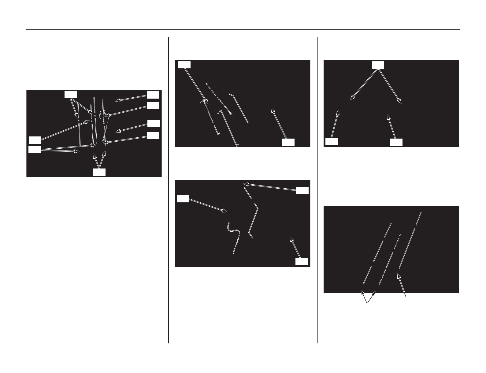
54 Servicing Your Honda
Subframe
14. While holding the license light stay assembly
(33), remove the mounting A bolts (34), collars
A (35), mounting B bolts (36), collars B (37)
and clip (38). Remove the license light stay
assembly from the rear fender B (23) while
releasing the license light wire from the rear
fender B.
15. Remove the rear fender B (23) while releasing
the front bosses from the air cleaner housing
(17).
16. Remove the bolt (39) and turn signal relay/
bracket (40) from the subframe (13).
17. Remove the positive (+) battery cable bands
(41), then release the positive (+) battery cable
(42) from the subframe (13).
18. Remove the fuse box assembly mounting bolt/
washer (43).
Remove the regulator/rectifier mounting bolts
(44).
(23) rear fender B (36) mounting B bolts
(33) license light stay assembly (37) collars B
(34) mounting A bolts (38) clip
(35) collars A
(33)
(38)
(34)
(35)
(23)
(37)
(37)
(36)
(17) air cleaner housing (23) rear fender B
(13) subframe
(39) bolt
(40) turn signal relay/bracket
(17)
(23)
(40)
(13)
(39)
(13) sub frame
(41) cable bands
(42) positive (+) battery cable
(43) fuse box assembly mounting bolt/washer
(44) regulator/rectifier mounting bolts
(13)
(42)
(41)
(43)
(44)
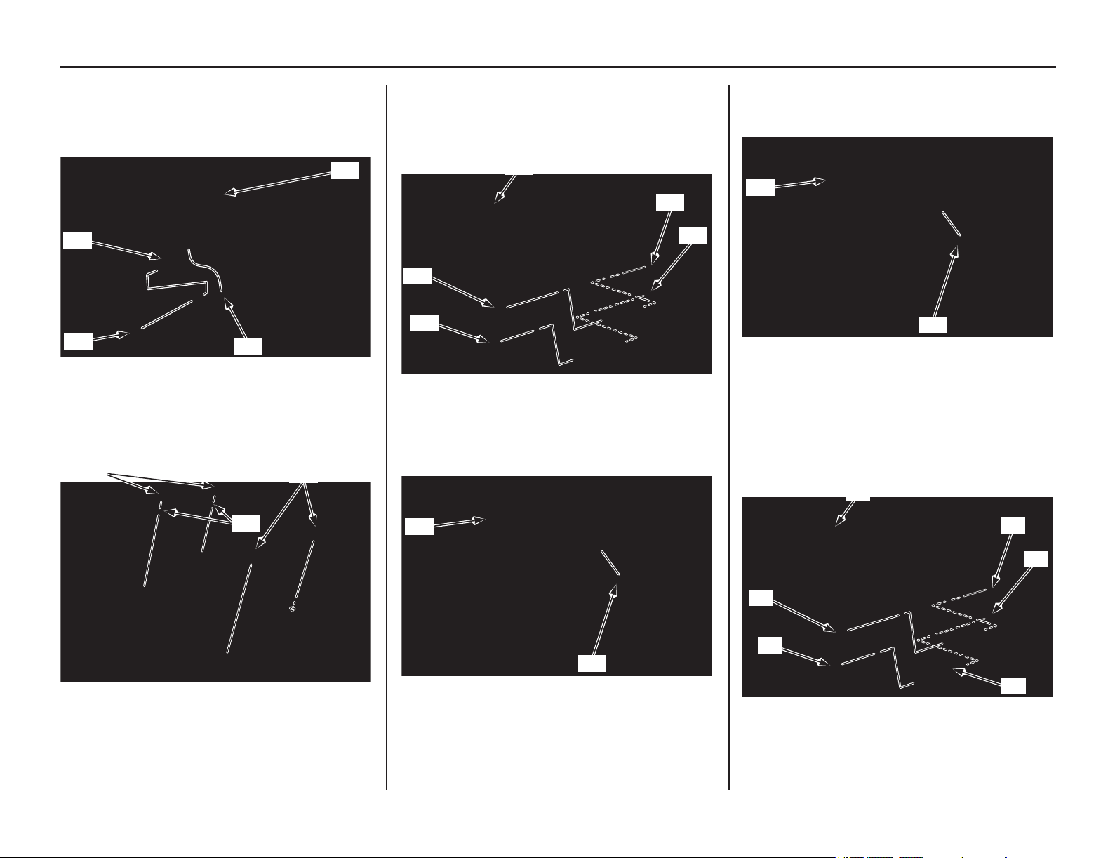
Subframe
(cont’d)
Servicing Your Honda 55
19. Remove the flange nut (45) and release the
wire harness guide (46) from the subframe.
Release the canister air tube (47) from the air
cleaner housing boss (48).
20. Remove the air cleaner housing mounting A
bolts (49), air cleaner housing mounting B
bolts (50) and collars (51).
21. Remove the subframe upper mounting bolts
(52) and lower mounting bolts (53).
Remove the subframe (1
3) to the rearward
being careful not to damage the wire harness.
22. Remove the air cleaner housing (17) from the
connecting tube (54).
Installation
1. Install the air cleaner housing (1) to the
connecting tube (2).
2. Loosely attach the upper and lower ends of the
subframe (3) to the main frame (4), while
installing the wire harness into place and
loosely install subframe upper mounting bolts
(5) and lower mounting bolts (6).
(45) flange nut (47) canister air tube
(46) harness guide (48) boss
(49) air cleaner housing mounting A bolts
(50) air cleaner housing mounting B bolts
(51) collars
(45)
(48)
(47)
(46)
(49)
(51)
(50)
(13) sub frame
(52) upper mounting bolts
(53) lower mounting bolts
(17) air cleaner housing
(54) connecting tube
(52)
(53)
(53)
(52)
(13)
(17)
(54)
(1) air cleaner housing
(2) connecting tube
(3) subframe
(4) main frame
(5) upper mounting bolts
(6) lower mounting bolts
(1)
(2)
(3)
(5)
(6)
(5)
(6)
(4)
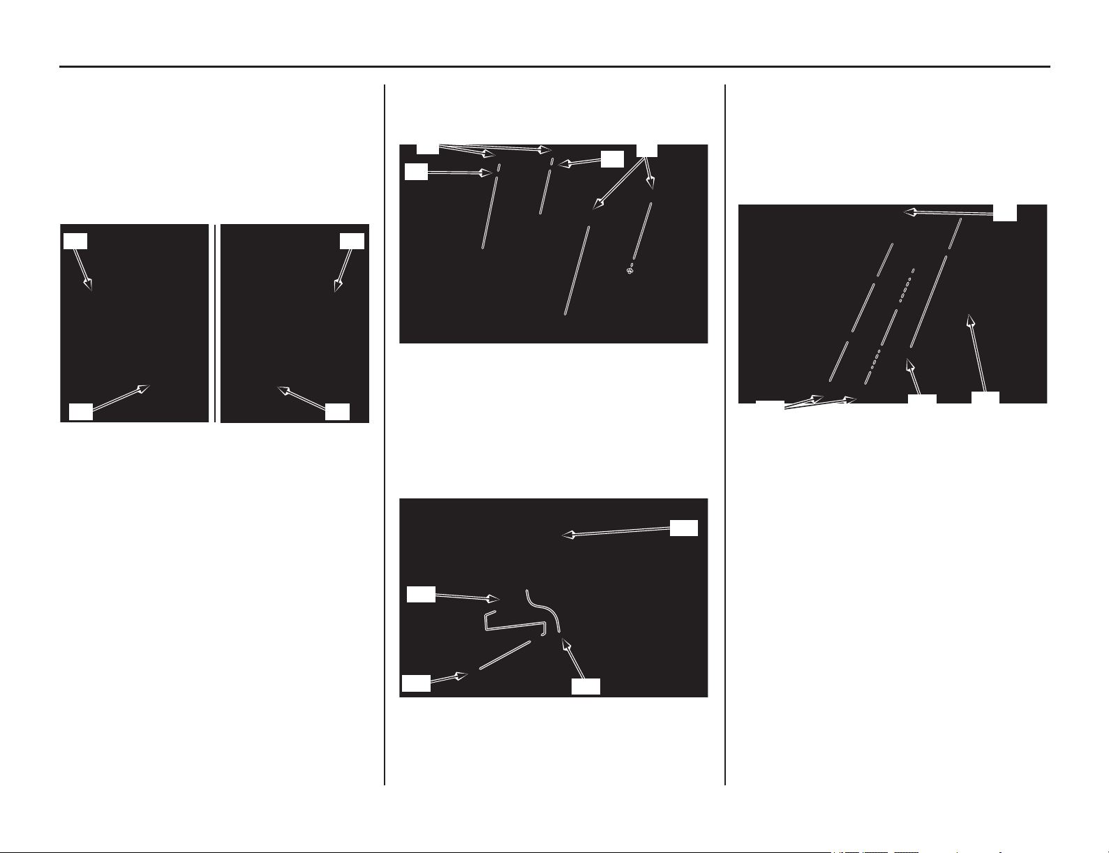
56 Servicing Your Honda
Subframe
3. Tighten the subframe upper mounting bolts (5)
first and then tighten the lower mounting bolts
(6) to the specified torque.
subframe upper mounting bolts:
24 lbf·ft (32 N·m, 3.3 kgf·m)
subframe lower mounting bolts:
36 lbf·ft (49 N·m, 5.0 kgf·m)
4. Install and tighten the air cleaner housing
mounting bolts A (7), collars (8) and air
cleaner housing mounting bolts B (9).
5. Install the wire harness guide (10) to the
subframe, then install and tighten the flange
nut (11). Route the canister air tube (12)
properly, then install it to the air cleaner
housing boss (13).
6. Install the fuse box assembly (14) to the air
cleaner housing (1). Install the fuse box
assembly mounting bolt/washer (15). Install
the regulator
/rectifier mounting bolts
(16).
Tighten the regulator/rectifier mounting bolts
and fuse box assembly mounting bolt/washer
securely.
(5) upper mounting bolts
(6) lower mounting bolts
Left side:
Right side:
(5) (5)
(6)(6)
(7) air cleaner housing mounting A bolts
(8) collars
(9) air cleaner housing mounting B bolts
(10) wire harness guide (12) canister air tube
(11) flange nut (13) boss
(8)
(9)
(8)
(7)
(11)
(13)
(12)
(10)
(1) air cleaner housing
(14) fuse box assembly
(15) fuse box assembly mounting bolt/washer
(16) regulator/rectifier mounting bolts
(15)
(16)
(1)
(14)
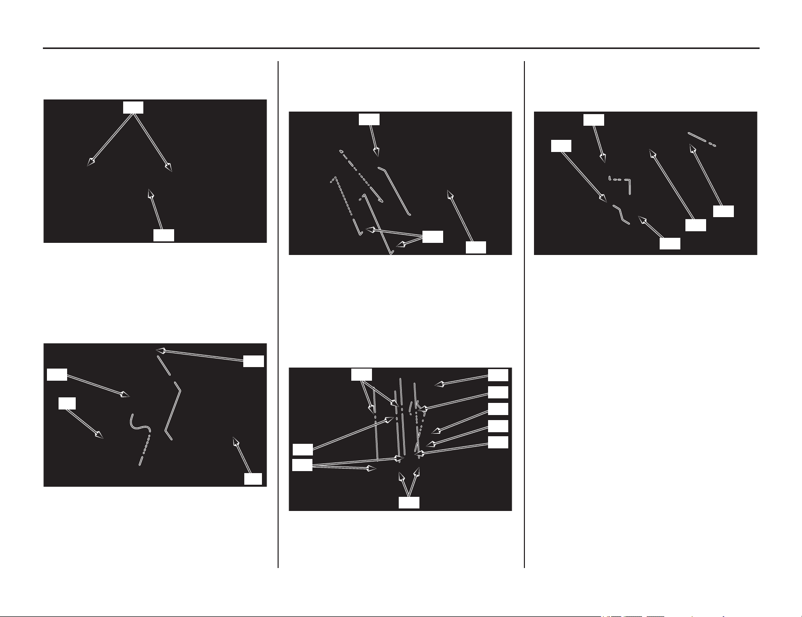
Subframe
(cont’d)
Servicing Your Honda 57
7. Route the positive (+) battery cable (16)
properly, secure it with the positive (+) battery
cable bands (17).
8. Install the turn signal relay/bracket (18)
between the subframe (3) and air cleaner
housing (1).
Install and tighten the bracket mounting bolt
(19).
9. Install the rear fender B (20) while installing
the front bosses (21) to the air cleaner housing
groove.
Route the wire harness (22) properly.
10. Attach the license light stay assembly (23) to
the rear fender B (20) while installing the
license light wire (24). Install the license light
stay assembly mounting A bolts (25), collars A
(26), mounting B bolts (27), collars B (28) and
clip (29).
11. Set the wire harness clip (30) to the rear fender
boss (31). Install the DLC connector (32) into
the rear fender groove. Secure the wire harness
(33) with the wire band (34).
(16) positive (+) battery cable
(17) cable bands
(1) air cleaner housing
(3) subframe
(18) turn signal relay/bracket
(19) bolt
(16)
(17)
(18)
(19)
(3)
(1)
(20) rear fender B (22) wire harness
(21) bosses
(20) rear fender B (26) collars A
(23) license light stay assembly (27) mounting B bolts
(24) license light wire (28) collars B
(25) mounting A bolts (29) clip
(20)
(22)
(21)
(24)
(29)
(25)
(26)
(20)
(28)
(28)
(27)
(23)
(30) wire harness clip (33) wire harness
(31) rear fender boss (34) wire harness band
(32) DLC connector
(30)
(32)
(31)
(34)
(33)
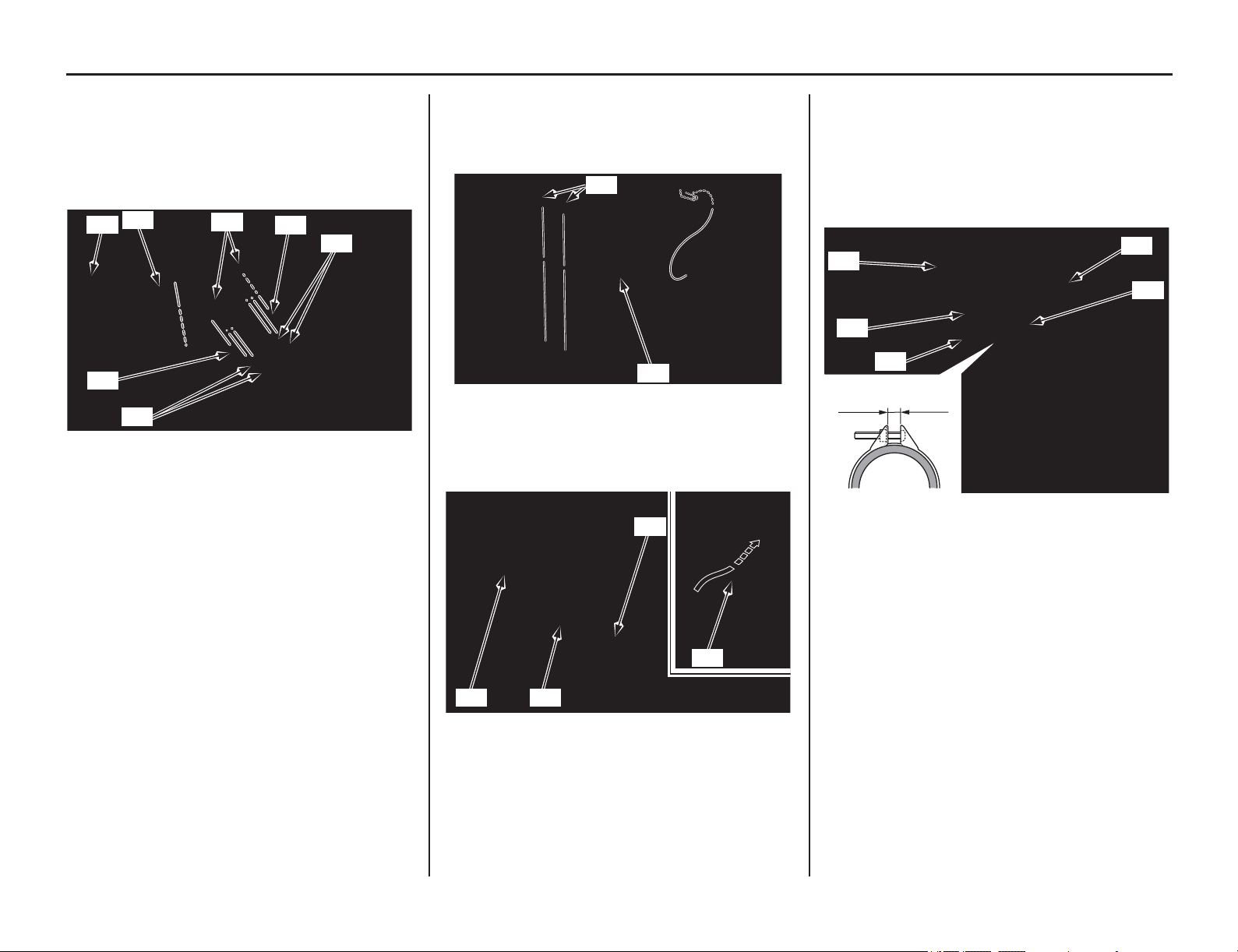
58 Servicing Your Honda
Subframe
12. Connect the turn signal light connectors (35).
Connect the license light/taillight/brake light
connectors (36). Set the connector covers (37)
to the rear fender stays (38).
Secure the wire harness (33) with the wire
ha
rness band (39).
13. Install the rear fender (40), then tighten the r
ear
fender mounting screws (41) to the specified
torque:
1.1 lbf·ft (1.5 N·m, 0.2 kgf·m)
14.
Route the negative (-) battery cable (42)
properly, secure it with negative (-) battery
cable bands (43).
15. Connect the crankcase breather tube (43) and
air injection air tube (44) to the air cleaner
housing (1). Connect the IAT sensor connector
(45).
Tighten the air cleaner connecting tube clamp
screw (46) so the clamp ends is 0.30 ±0.06
in(7.5 ± 1.5 mm).
(33) wire harness
(35) turn signal connectors
(36) license light/taillight/brake light connectors
(37) connector covers
(38) rear fender stays
(39) wire harness band
(39)
(37)
(35)
(36)
(38)
(38)
(33)
(40) rear fender (41) screws
(42) negative (-) battery cable (43) cable bands
(40)
(41)
(42)
(42)(43)
(43)
(1) air cleaner housing
(43) crankcase breather tube
(44) air injection air tube
(45) IAT sensor connector
(46) connecting tube band screw
(43)
(45)
0.30 ± 0.06 in
(7.5 ± 1.5 mm)
(44)
(1)
(46)
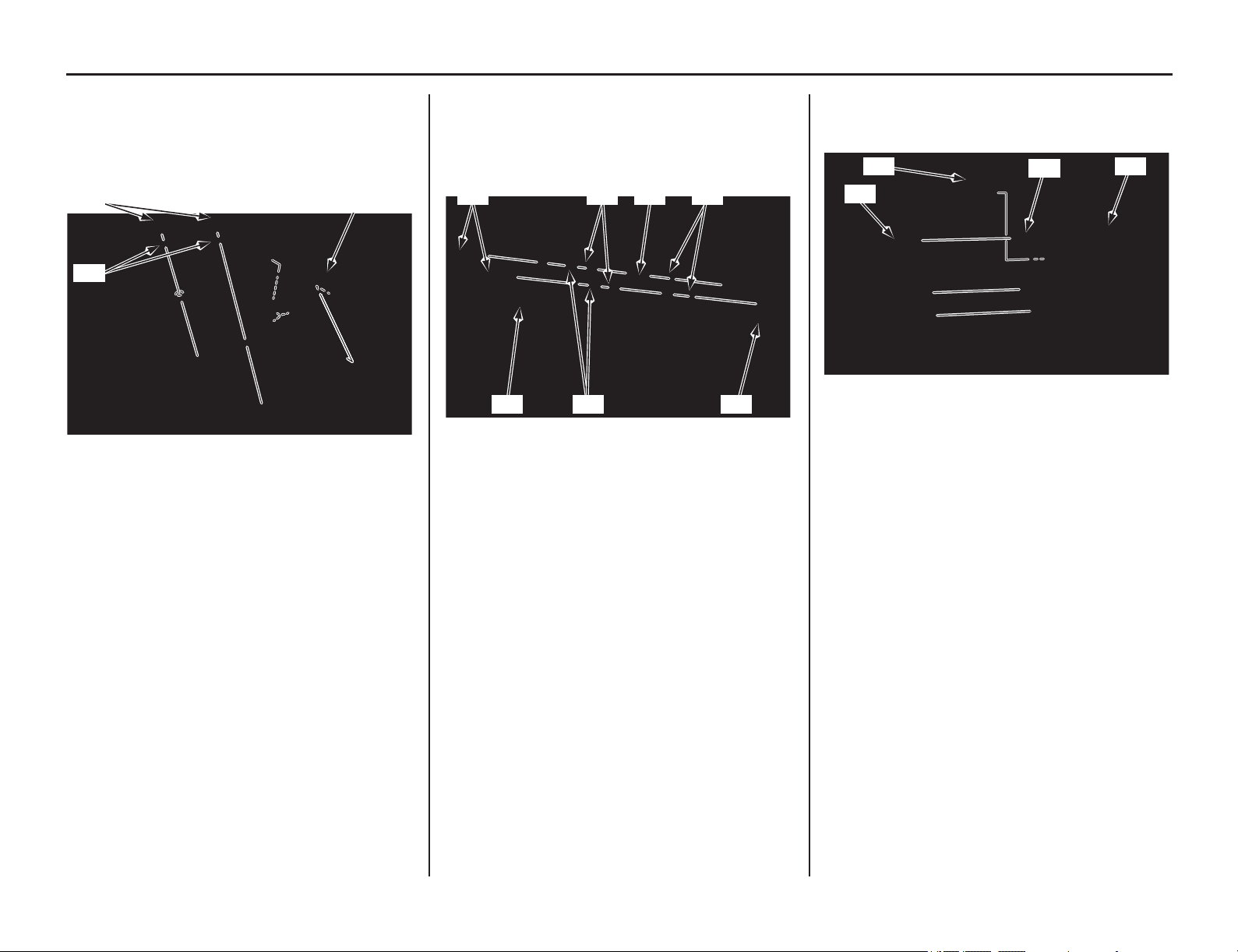
Servicing Your Honda 59
Subframe
16. Install the seat support base (47) to the
subframe. Install the collars (48) and mounting
bolts (49), then tighten the mounting bolts to
the specified torque:
7 lbf·ft (10 N·m, 1.0 kgf·m)
17. Install the bank angle sensor assembly (50) to
the seat support base (47) using the washers
(51), collars B (52), collars A (53), ECM stay
(54) and stay mounting bolts (55), then tighten
the bolts securely.
18. Install the starter relay (56) to the seat support
base (47). Install the ECM (57) to the ECM
stay (54).
19. Install the left side cover (page 47).
20. Install the muffler (page 133).
21. Install the fuel tank (page 50).
22. Install the battery (page 139).
(47) seat support base
(48) collars
(49) bolts
(49)
(48)
(47)
(47) seat support base
(50) bank angle sensor assembly
(51) washers
(52) collars B
(53) collars A
(54) ECM stay
(55) bolts
(55)
(54) (53)
(52) (50) (51)
(47)
(47) seat support base (56) starter relay
(54) ECM stay (57) ECM
(47)
(54)
(56)
(57)
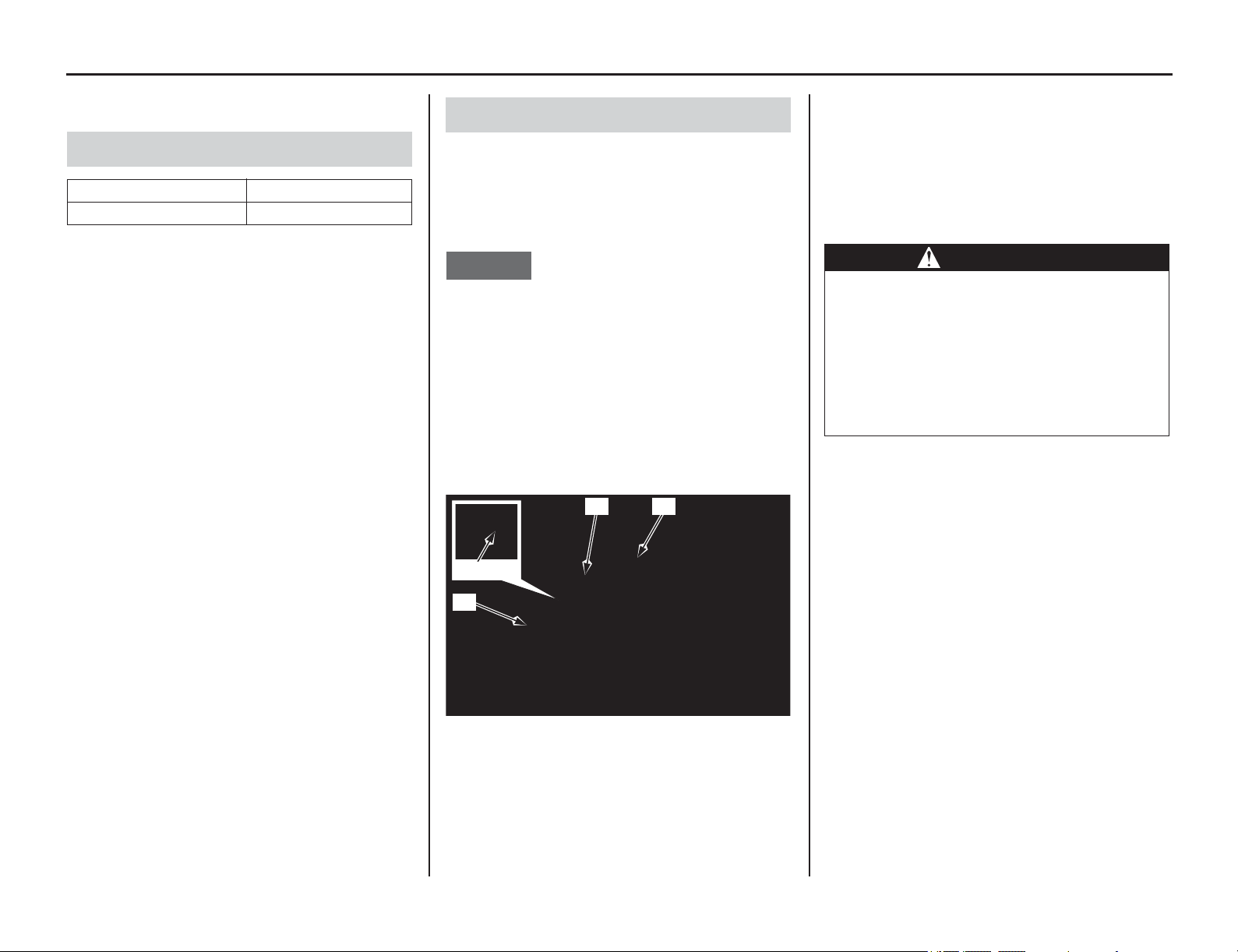
Fuel System
60 Servicing Your Honda
Fuel System
Refer to Important Safety Precautions on page 33.
Use only unleaded fuel in your motorcycle. The
use of leaded fuel will damage the catalytic
converter (s). If you ride your motorcycle in a
country where leaded fuel might be available, take
precautions to use only unleaded fuel.
Your engine is designed to use any unleaded
gasoline that has a pump octane number of 91 or
higher. Gasoline pumps at service stations
normally display the pump octane number.
For information on the use of oxygenated fuels, see
page 187.
Use of lower octane gasoline can cause persistent
“pinging” or “spark knock” (a louder rapping
noise) which, if severe, can lead to engine damage.
(Light pinging experienced while operating under
a heavy load, such as climbing a hill, is no cause
for concern.)
If pinging or spark knock occurs at a steady engine
speed under normal load, change brands of
gasoline. If pinging or spark knock persists,
consult your dealer.
Never use stale or contaminated gasoline. Avoid
getting dirt, dust or water in the fuel tank.
If mud is on the fuel fill cap (1) and fuel tank top
shelter (2) at time of refueling, remove the mud
before refueling.
1. To open the fuel fill ca
p turn the fuel fill cap
counterclockwise and remove it.
NOTICE
Equivalent or modified parts must comply with
applicable Air Resource Board (ARB) evaporative
emission control regulations. Non-compliance
may result in civil litigation or criminal
prosecution.
The fuel cap may not be disassembled. When
replacing, consult with a dealer and replace with
a Honda genuine fuel cap or one that complies
with Air Resource Board (ARB) evaporative
emission control regulations.
2. Add fuel until the level reaches the bottom of
the filler neck (3).
Fuel Tank Capacity: 2.01 US gal (7.6 ℓ)
• Be careful not to damage the fuel pump while
filling the fuel tank.
• Avoid overfilling the tank. There should be no
fuel in the filler neck.
3. After refueling, turn the fuel fill cap clockwise
until it clicks.
• If the breather tube (4) is twisted, turn the
rotary joint to correct.
• If you replace the fuel cap, use a Honda
Genuine replacement part or equivalent.
Fuel
Type Unleaded
Pump Octane Number 91 (or higher)
Refueling Procedure
(1) fuel fill cap (3) filler neck bottom
(2) top shelter (4) breather tube
(2)
(4)
(3)
(1)
WARNING
Gasoline is highly flammable and
explosive. You can be burned or seriously
injured when handling fuel.
• Stop the engine and keep heat, sparks
and flame away.
• Handle fuel only outdoors.
• Wipe up spills immediately.
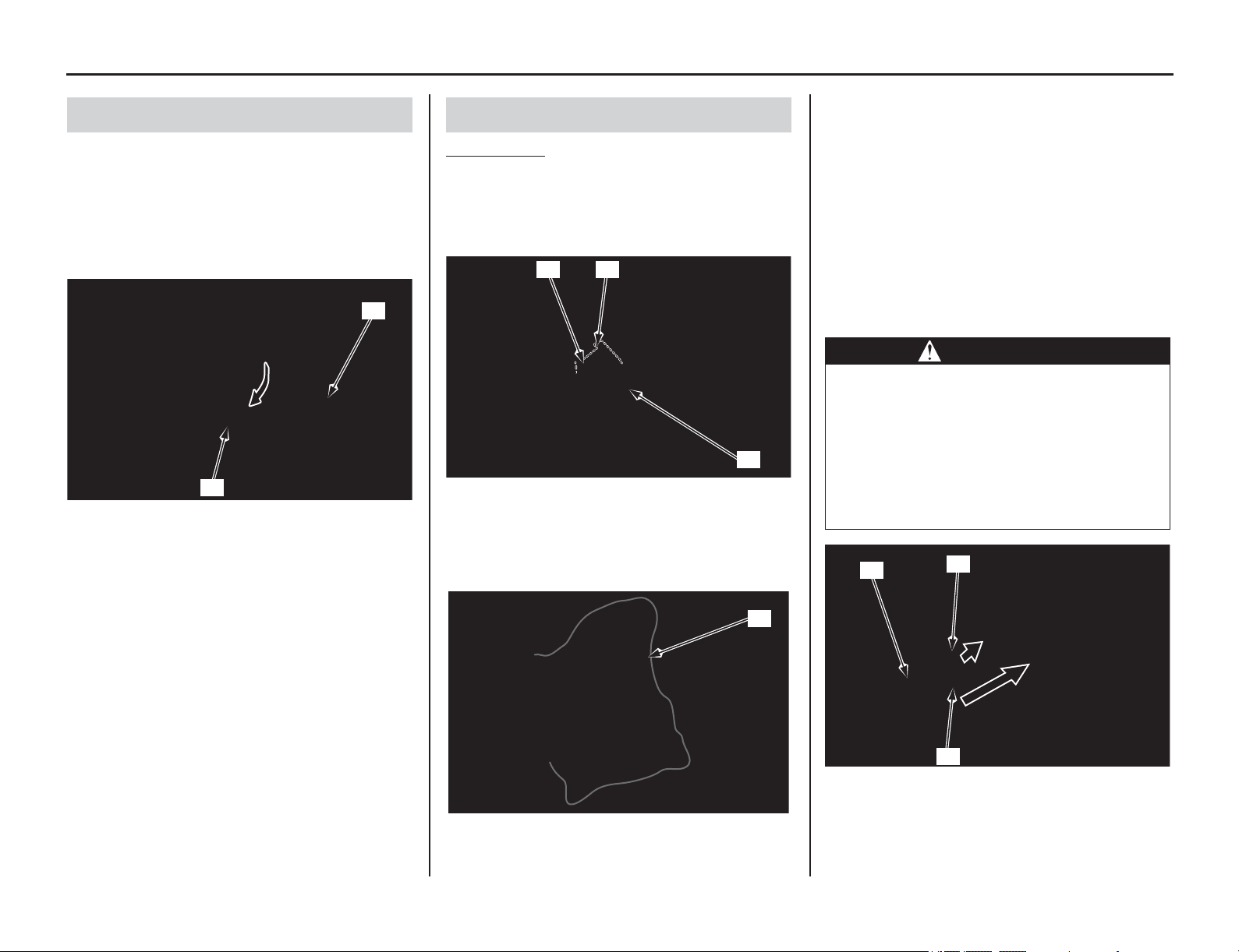
Fuel System
(cont’d)
Servicing Your Honda 61
1. Hang the fuel tank to the left side of the frame
(page 48).
2. Remove the fuel quick connect fitting cover
(1).
3. Check the fuel line (2) for cracks,
deterioration, damage or leakage. Replace the
fuel line, if necessary.
4. Install the fuel quick connect fitting cover.
5. Install the fuel tank (page 50).
Disconnection
1. Remove the fuel tank (page 48).
2. Check the fuel quick connect fitting (1) for
dirt, and clean if necessary.
3. Remove the bolt (2), clamp and setting rubber
(3).
4. Place a shop towel (4) over the fuel quick
connect fitting.
5. Unlock the slide retainer (5) of the quick
connect fitting by completely pulling it up.
Release the fuel quick connect fitting from the
fuel joint (6) while holding the connector
housing (7).
• Use a shop towel to absorb the remaining
fuel in the fuel feed hose.
• Be careful not to damage the hose or other
parts.
• Do not use tools.
• Dirt intruding into the connector housing
may cause slide retainer sticking.
Fuel Line Inspection
(1) fuel quick connect fitting cover
(2) fuel line
(1)
(2)
Fuel Line Replacement
(1) fuel quick connect fitting
(2) bolt
(3) clamp and setting rubber
(4) shop towel
(2)
(1) (3)
(4)
WARNING
Gasoline is highly flammable and
explosive. You can be burned or seriously
injured when handling fuel.
• Stop the engine and keep heat, sparks
and flame away.
• Handle fuel only outdoors.
• Wipe up spills immediately.
(5) slide retainer
(6) fuel joint
(7) connector housing
(5)
(6)
(7)
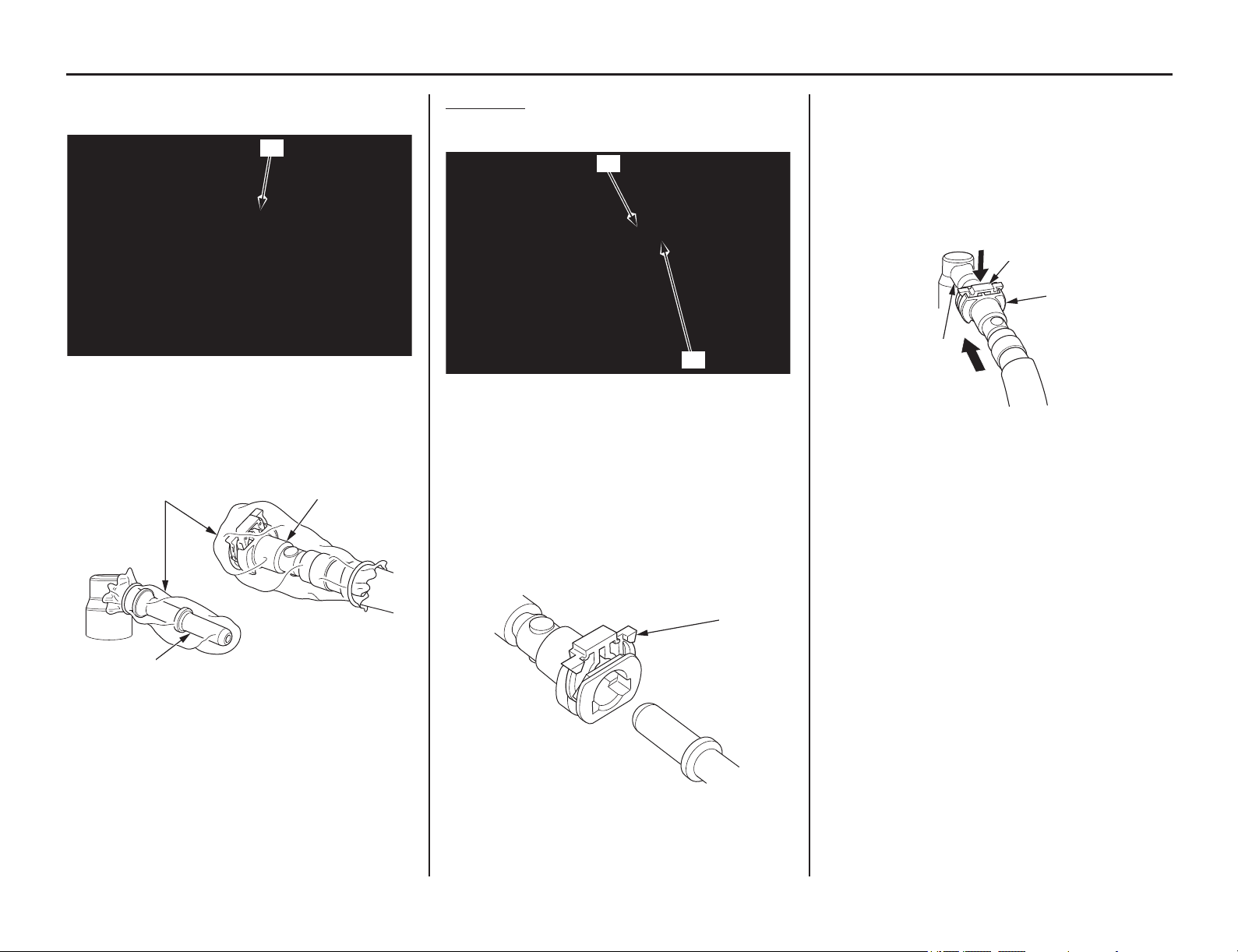
62 Servicing Your Honda
Fuel System
6. Remove the rubber cover (8) from the fuel
joint of the fuel pump.
7. To prevent damage and keep foreign matter
out, cover the disconnected connector (9) and
fuel joint (6) with plastic bags (10).
Connection
1. Install the rubber cover (1) onto the fuel joint
(2) of the fuel pump as shown.
2. Be sure that the slide retainer (3) is completely
pulled up before connecting the quick connect
fitting.
• Do not bend or twist the fuel feed hose.
• Do not reuse the kinked or damaged fuel
hose.
• Do not use gloves or a shop towel while
installing the quick connect fitting.
3. Connect the quick connect fitting to the fuel
joint (2) until you hear the “click” while
holding the connector housing (4). Lock the
slide retainer (3) by pushing it until you hear
the “click”.
If it is hard to connect, put a small amount of
engine oil on the pipe end of the fuel joint.
4. Make sure the connection is secure and that the
slide retainer is firmly locked into place; check
visually and by pulling the connector housing.
(8) rubber cover
(6) fuel joint
(9) disconnected connector
(10) plastic bags
(8)
(10)
(9)
(6)
(1) rubber cover
(2) fuel joint
(3) slide retainer
(1)
(2)
(3)
(2) fuel joint (4) connector housing
(3) slide retainer
(3)
(4)
(2)
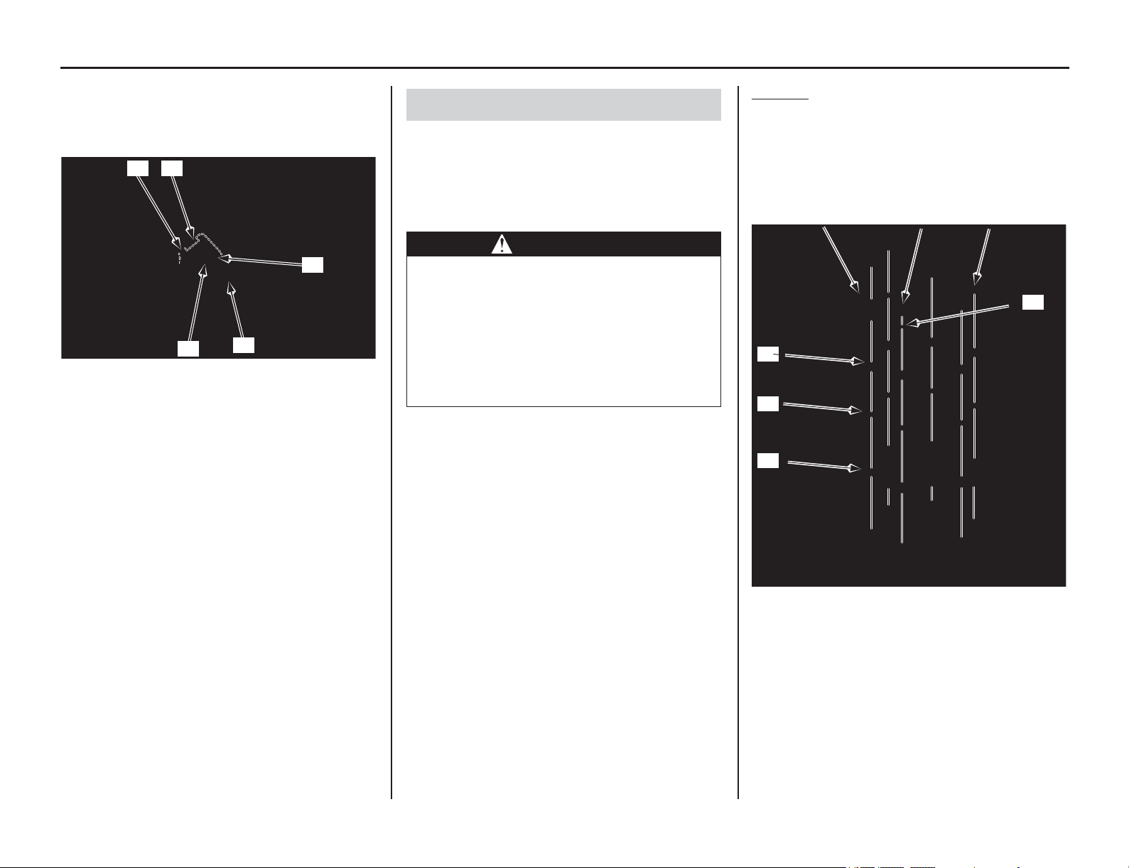
Fuel System
(cont’d)
Servicing Your Honda 63
5. Install the setting rubber (5), clamp (6) and bolt
(7) by aligning the clamp tab (
8) with the
groove (9) of the st
ay.
Tighten the bolt securely.
6. Install the fuel tank (page 50).
7. Increase the fuel pressure (page 68).
Empty the fuel tank into an approved gasoline
container using a commercially available hand
siphon or an equivalent method.
Be careful not to damage the fuel pump while
draining the fuel in the fuel tank.
Removal
1. Remove the fuel tank (page 48).
2. Remove the fuel pump mounting nuts (1), fuel
pump mounting cap nut (2), stopper cable
guide (3), washer (4), collars (5), conical
spring washers (6) and fuel pump plate (7)
while holding the fuel tank.
(5) setting rubber (8) clamp tab
(6) clamp (9) groove
(7) bolt
(6)
(7)
(5)
(9)
(8)
Fuel Pump Filter Replacement
WARNING
Gasoline is highly flammable and
explosive. You can be burned or seriously
injured when handling fuel.
• Stop the engine and keep heat, sparks
and flame away.
• Handle fuel only outdoors.
• Wipe up spills immediately.
(1) fuel pump mounting nuts
(2) fuel pump mounting cap nut
(3) stopper cable guide
(4) washer
(5) collars
(6) conical spring washers
(7) fuel pump plate
(5)
(7)
(4)
(3) (2) (1)
(6)
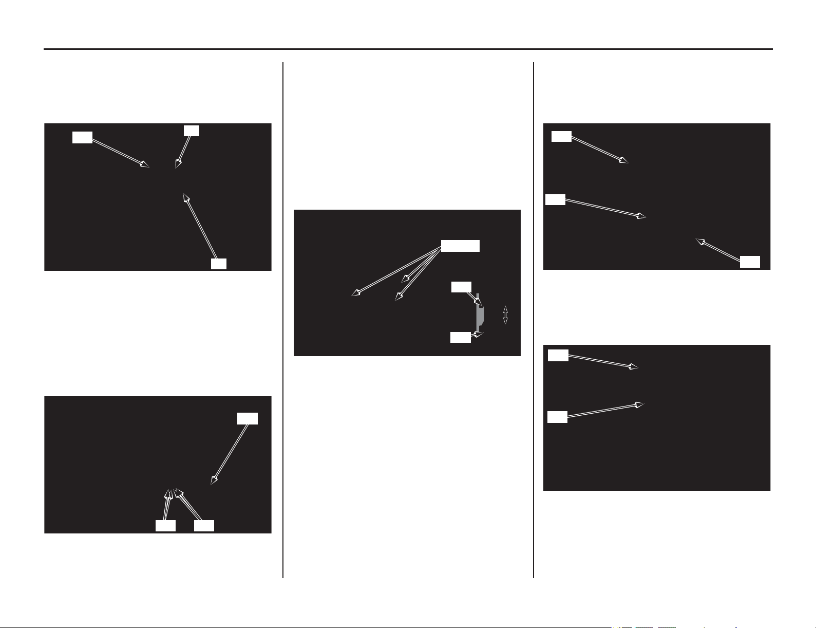
64 Servicing Your Honda
Fuel System
3. Remove the fuel pump unit (8), dust seal (9)
and O-ring (10).
Be careful not to damage the fuel pump unit and
reserve sensor.
4. Disconnect the fuel pump wire terminals (11)
and fuel reserve sensor wire terminals (12)
from the fuel pump base (13).
Be careful not to damage the wires when
disconnecting the fuel reserve sensor wire
terminals and fuel pump wire terminals.
5. Check the hooks (14) of the fuel pump unit
holder and tabs (15) on the fuel pump base for
damage or discoloration.
If the hooks and tabs are damaged or
discolored, replace the
fuel pump unit
as an
assembly.
6.
Release the hooks of the fuel pump unit
holder
from the groove
s (16) in the fuel pump bas
e
tabs while pushing the holder against the base
and slightly spreading the base tabs.
Be careful not to damage the hooks and tabs.
7.
Remove the fuel pump unit holder assembly
(17) from the fuel pump base (13) and remove
the O-ring (18).
Wipe the spilled out fuel immediately.
8.
Remove the fuel pump stopper (19) and
damper rubber (20).
(8) fuel pump unit (10) O-ring
(9) dust seal
(11) fuel pump wire terminals
(12) reserve sensor wire terminals
(13) fuel pump base
(10)
(9)
(8)
(13)
(12)(11)
(14) hooks (16) grooves
(15) tabs
(15)
(16)
(14)
(14)
(15)
(13) fuel pump base
(17) fuel pump unit holder assembly
(18) O-ring
(19) fuel pump stopper
(20) damper rubber
(17)
(18)
(13)
(19)
(20)
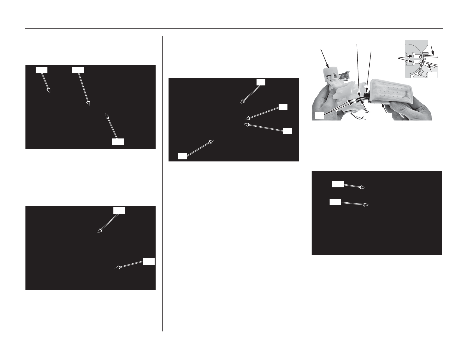
Fuel System
(cont’d)
Servicing Your Honda 65
9. Remove the fuel pump assembly (21) from the
fuel pump unit holder (22).
10. Remove the O-ring (23) from the fuel pump
assembly (21).
11. Remove the fuel pump filter (24) from the fuel
pump assembly (21).
12. Check the fuel pump filter for clog, damage or
deterioration and replace it if necessary.
Installation
1. Install the fuel pump filter (1) onto the fuel
pump assembly (2) aligning its hook (3) with
the joint boss (4) completely.
Be careful not to damage the hook.
2. Apply small amount of engine oil to a new
O-ring (5).
Install a new O-ring to the fuel pump assembly
(2).
3. Install the fuel pump assembly with fuel pump
filter into the fuel pump unit holder (6) while
routing the fuel pump yellow (7) and green (8)
wires through the holder grooves (9) as shown.
4. Install a new damper rubber (10) to the fuel
pump filter as shown.
Install fuel pump stopper (11).
(21) fuel pump assembly
(22) fuel pump unit holder
(23) O-ring
(21) fuel pump assembly
(24) fuel pump filter
(21)
(23)(22)
(21)
(24)
(1) fuel pump filter (3) hook
(2) fuel pump assembly (4) joint boss
(2)
(3)
(4)
(1)
(2) fuel pump assembly (7) yellow wire
(5) O-ring (new) (8) green wire
(6) fuel pump unit holder (9) grooves
(10) damper rubber (new)
(11) fuel pump stopper
(9)
(8)
(6)
(7)
(5)
(9)
(7)
(8)
(2)
(11)
(10)
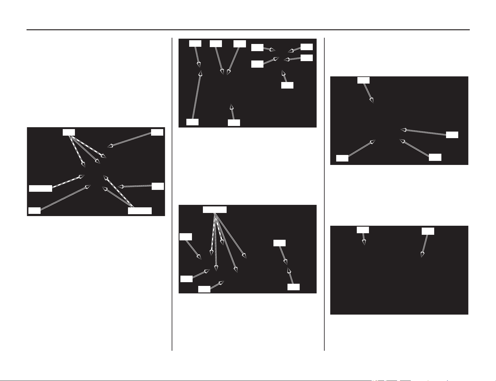
66 Servicing Your Honda
Fuel System
5. Apply small amount of engine oil to a new
O-ring (12).
Install a new O-ring to the fuel pump base (13).
6. Install the fuel pump unit holder assembly (14)
into the fuel pump base while aligning its
hooks (15) with the grooves (16) in the fuel
pump base tabs (17).
If the gap between the hooks and tabs is more
than 0.04 in (1.0 mm), replace the fuel pump
unit.
Be sure that the hooks are completely seated.
7. Connect the fuel pump yellow (18) and green
(19) wire terminals to the fuel pump base
terminals (20). Route the fuel reserve level
sensor wires properly, connect the white (21)
and black (22) wire terminals to the fuel pump
base terminals. Push the wire terminals until
they stop as shown.
Be careful not to damage the wires.
8. Install a new dust seal (23) by aligning its tabs
(24) with the fuel pump unit grooves (25).
Check the dust seal lug (26) which is located the
index mark (27) of the fuel pump base (13).
9. Apply small amount of engine oil to a new
O-ring (28).
Install a new O-ring into the between the dust
seal (29) and collar (30) of the fuel pump unit
(31).
10. Install the fuel pump unit (31) into the fuel tank
(32) with its hose joint facing forward.
Be careful not to damage the fuel pump unit and
reserve sensor.
(12) O-ring (new)
(13) fuel pump base
(14) fuel pump unit holder assembly
(15) hooks
(16) grooves
(17) tabs
(13)
(16) (17)
(12)
(17)(16)
(14)
(15)
(18) yellow wire terminal
(19) green wire terminal
(20) fuel pump base terminals
(21) white terminal
(22) black terminal
(13) fuel pump base (25) grooves
(23) dust seal (new) (26) dust seal lug
(24) tabs (27) index mark
(18)
(22)
(20)
(21)
(20)
(19)
(19)
(21)
(18)
(22)
(13)
(23)
(26)
(27)
(26)
(24) (25)
(28) O-ring (new) (30) collar
(29) dust seal (31) fuel pump unit
(31) fuel pump unit
(32) fuel tank
(30)
(31)
(28)
(29)
(31)
(32)
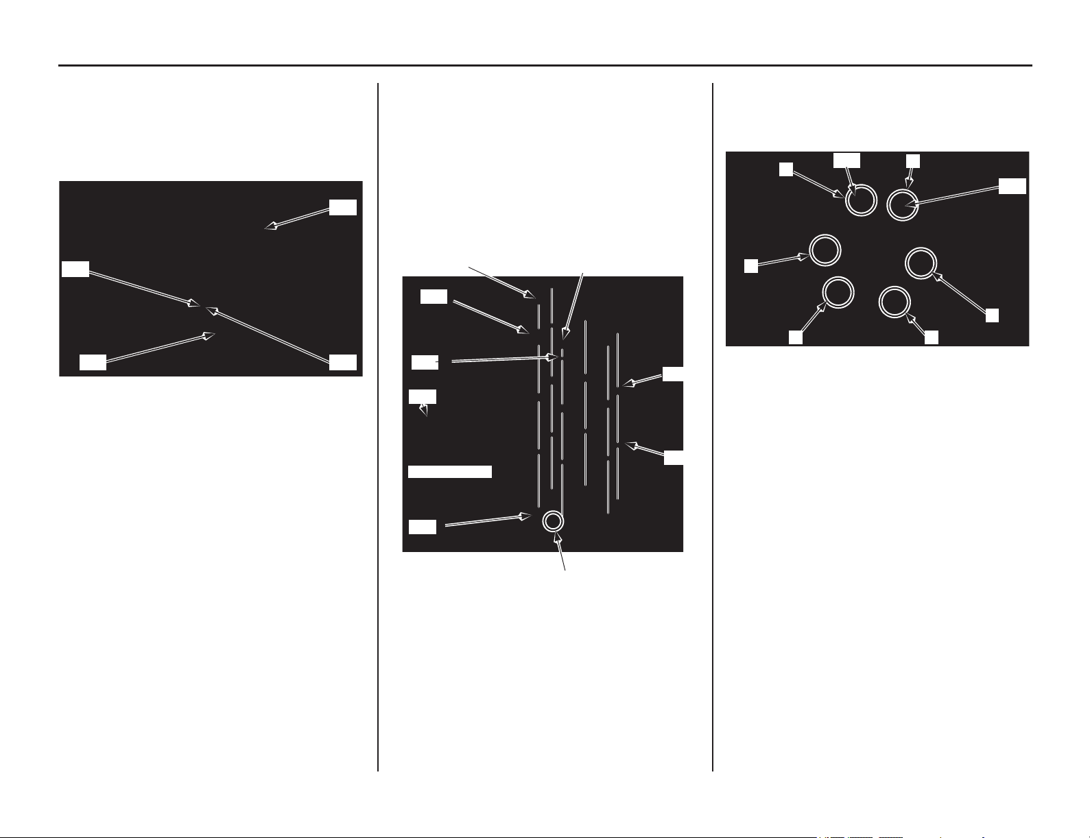
Servicing Your Honda 67
Fuel System
11. Install the fuel pump plate (33) by aligning
with its groove (34) with fuel pump unit lug
(35).
Check the dust seal lug (26) is in position as
shown.
12. Install the conical spring washers (36), collars
(37), washer (38), stopper cable guide (39),
fuel pump mounting nuts (40) and fuel pump
mounting cap nut (41).
Make sure that the convex surfaces of the conical
spring washers are upside.
Make sure that the cap nut is in position of the
identification mark (42) on the fuel pump plate
(33).
13. Tighten the fuel pump mounting nuts (40) and
cap nut (41) to the specified torque in the
specified sequence as shown:
8 lbf·ft (11 N·m, 1.1 kgf·m)
14. Install the fuel tank (page 50).
15. Increase the fuel pressure (page 68).
(26) dust seal lug
(33) fuel pump plate
(34) fuel pump plate groove
(35) fuel pump unit lug
(27) (35)
(34)
(33)
(33) fuel pump plate
(36) conical spring washers
(37) collars
(38) washer
(39) stopper cable guide
(40) fuel pump mounting nuts
(41) fuel pump mounting cap nut
(42) identification mark
(37)
(36)
(33)
(36)
Fuel tank side
(39)
(40)
(41)
(42)
(38)
(40) fuel pump mounting nuts
(41) fuel pump mounting cap nut
4
(41)
(40)
2
1
5
3
6

68 Servicing Your Honda
Fuel System
Make sure the fuel remains enough (0.3 US gal
(1.0 Ɛ) minimum) in the fuel tank and add fuel if
necessary before increasing fuel pressure.
With the throttle closed.
Pull the clutch lever all the way in, and depress the
start button.
The engine will start up by increasing the fuel
pressure.
If the engine does not start, check all connector
connections and/or refer to an official Honda
Service Manual (page 194) for troubleshooting of
the PGM-FI symptom.
Fuel Pressure Increasing
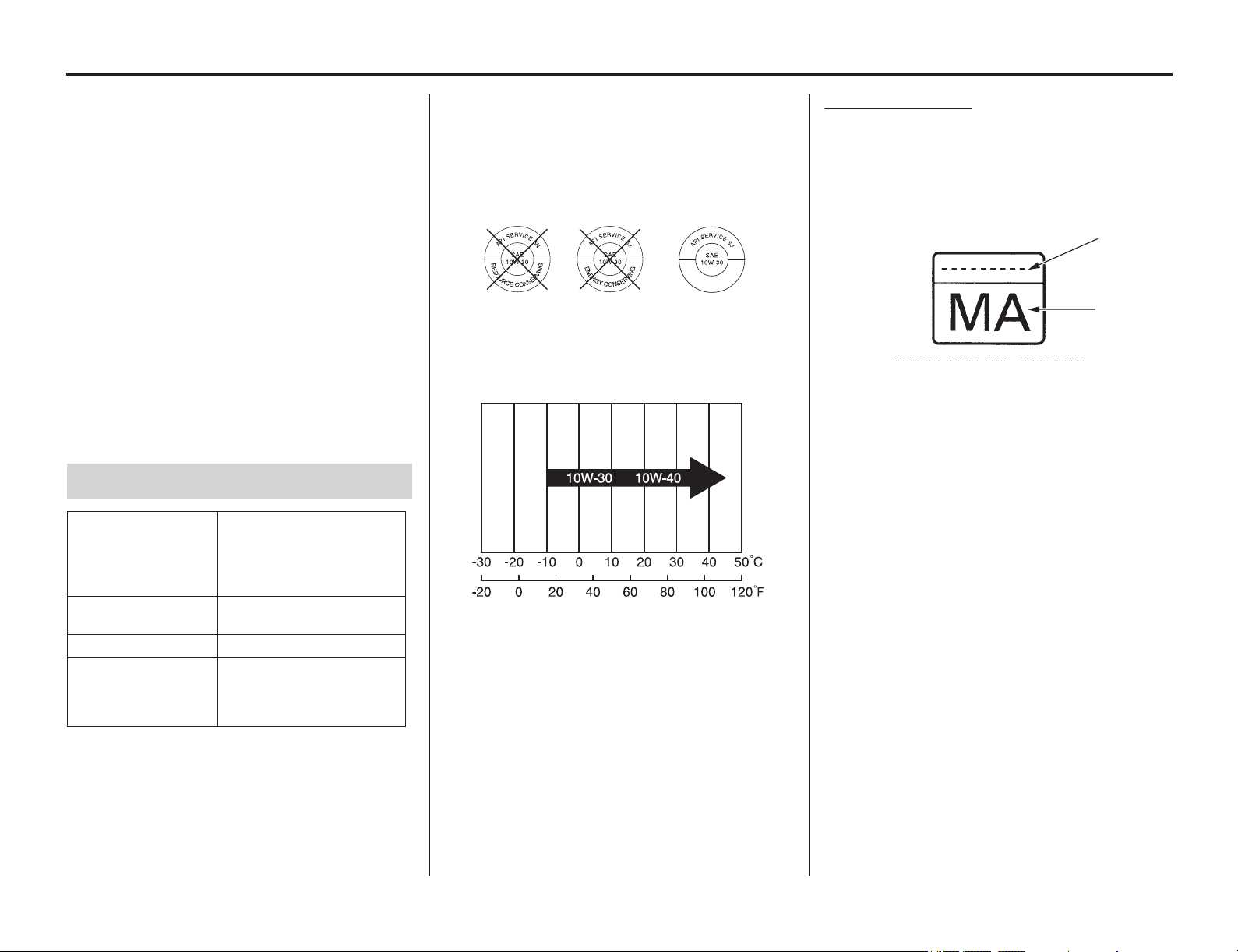
Engine Oil
Servicing Your Honda 69
Refer to Important Safety Precautions on page 33.
Using the proper oil and oil filter, and regularly
checking, adding, and changing oil
will help
extend the service life of the engine. Even the best
oil wears out. Changing oil helps get rid of dirt and
deposits. Operating the engine with old or dirty oil
can damage your engine. Running the engine with
insufficient oil can cause serious damage to the
engine.
Change the engine oil as specified in the
maintenance schedule on pages 36, 37.
When running in very dusty conditions, oil
changes should be performed more frequently than
specified in the maintenance schedule.
When riding at high or continuous speed on the
highway, check the oil level frequently.
* Suggested 4-stroke engine oils are equal performance
to SJ oils that are not labeled as energy conserving or
resource conserving on the circular API service label.
• Your motorcycle does not need oil additives.
Use the recommended oil.
• Do not use API SH or higher 4-stroke engine oils
displaying a circular API “energy conserving” or
“resource conserving” service label on the
container. They may affect lubrication.
Other viscosities shown in the following chart may
be used when the average temperature in your
riding area is within the indicated range.
JASO T 903 standard
The JASO T 903 standard is an index for engine
oils for 4-stroke motorcycle engines.
There are two classes: MA and MB.
Oil conforming to the standard is labeled on the oil
container. For example, the following label shows
the MA classification.
Oil Recommendation
API
classification
SG or higher except oils
labeled as energy
conserving or resource
conserving on the circular
API service label
viscosity
(weight)
SAE 10W-30
JASO T 903 standard MA
suggested oil* Pro Honda GN4 4-stroke
Oil (USA & Canada), or
Honda 4-stroke oil, or an
equivalent motorcycle oil
NOT RECOMMENDED RECOMMENDED
(1) oil code
(2) oil classification
(1)
(2)
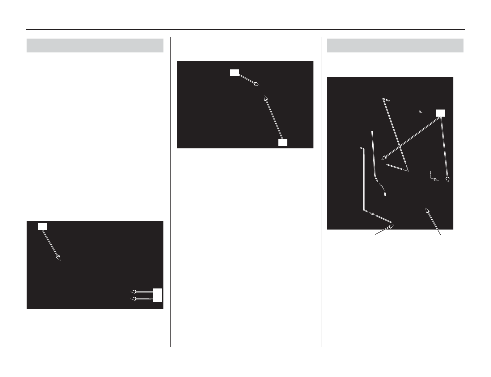
70 Servicing Your Honda
Engine Oil
1. Run the engine at idle for 3 minutes, then shut
it off.
2. Wait 3 minutes after shutting off the engine to
allow the oil to properly distribute itself in the
engine.
3. Support the motorcycle in an upright position
on a level surface.
4. Remove the engine oil fill cap/dipstick (1)
from the left crankcase cover, wipe it clean,
and insert it without screwing it in. Remove the
oil fill cap/dipstick.
5. Check that the oil level is between the upper
(2) and lower (3) level marks on the engine oil
fill cap/dipstick.
• If the oil is at or near the upper level mark,
you do not have to add oil.
• If the oil is below or near the lower level
mark, add the recommended oil until it
reaches the upper level mark. (Do not
overfill.)
Reinstall the engine oil fill cap/dipstick.
Repeat steps 1 – 5.
6. Check that the O-ring (4) is in good condition
and replace it if necessary.
7. Reinstall the engine oil fill cap/dipstick (1).
8. Check for oil leaks.
1. Remove the engine guard A bolts/washers (1),
B bolt/washer (2) and engine guard (3).
2. Run the engine at idle for 3 minutes, then shut
it off.
3. Support the motorcycle in an upright position
on a level surface.
4. Remove the engine oil fill cap/dipstick (4)
from the left crankcase cover.
Checking & Adding Oil
(1) engine oil fill cap/dipstick
(2) upper level mark
(3) lower level mark
(1)
(2)
(3)
(1) engine oil fill cap/dipstick
(4) O-ring
(1)
(4)
Changing Engine Oil & Filter
(1) engine guard A bolts/washers
(2) engine guard B bolt/washer
(3) engine guard
(1)
(3)
(2)

Servicing Your Honda 71
Engine Oil
5. Place an oil drain pan under the engine to catch
the oil. Then remove the engine oil drain bolt
(5) and O-ring (6).
6.
After the oil has drained, apply engine oil to
the drain bolt threads, seating surface and a
new O-ring, then
install the O-ring on the drain
bolt and tighten the drain bolt to the specified
torque:
13 lbf·ft (18 N·m, 1.8 kgf·m)
Pour the drained oil into a suitable container and
dispose of it in an approved manner (page 160).
NOTICE
Improper disposal of drained fluids is harmful to
the environment.
7. (Off-Road Use)
It is recommended to replace the oil and filter
every 8 races or about every 30.0 hours.
However, if you replace only the oil before the
recommended interval, see page 36.
8. Remove the left crankcase over cover bolts (7)
and over cover (8).
9. Remove the oil filter cover bolts (9) and oil
filter cover (10).
10. Remove the oil filter (11), O-ring (12) and
spring (13).
NOTICE
Using the wrong oil filter may result in leaks or
engine damage.
11. Apply grease to the filter side of the spring end,
then install the spring into a new oil filter.
12. Position the spring against the engine
crankcase and install a new oil filter with the
rubber seal (14) facing out, away from the
engine. You should see the “OUT-SIDE” mark
(15) on the filter body, near the seal.
Use a new Honda Genuine oil filter or a filter
of equal quality specified for your model.
NOTICE
If the oil filter is not installed properly, it will
cause serious engine damage.
13. Apply engine oil to a new O-ring and install it
to the oil filter cover.
14. Install the oil filter cover being careful not to
damage the O-ring, then tighten the oil filter
cover bolts to the specified torque:
7 lbf·ft (10 N·m, 1.0 kgf·m)
15. Install the left crankcase over cover, then tighten
the over cover bolts to the specified torque:
7 lbf·ft (10 N·m, 1.0 kgf·m)
16. Install the engine guard, then tighten the
engine guard A bolts/washers and B bolt/
washer to the specified torque:
7 lbf·ft (10 N·m, 1.0 kgf·m)
17. Fill the crankcase with the recommended oil.
18. Install the engine oil fill cap/dipstick.
19. Check the engine oil level by following the
steps in Checking & Adding Oil (page 70).
Pour the drained oil into a suitable container and
dispose of it in an approved manner (page 160).
NOTICE
Improper disposal of drained fluids is harmful to
the environment.
(4) engine oil fill cap/dipstick
(5) engine oil drain bolt
(6) O-ring (new)
(6)
(4)
(5)
(7) bolts (8) over cover
(9) oil filter cover bolts (13) spring
(10) oil filter cover (14) rubber seal
(11) oil filter (15) “OUT-SIDE” mark
(12) O-ring
(8)
(7)
(12)(13)
(10)
(15)
(9)
(11) (14)
Capacity: 1.22 US qt (1.15 ℓ)
after draining and filter change
1.16 US qt (1.10 ℓ)
after draining
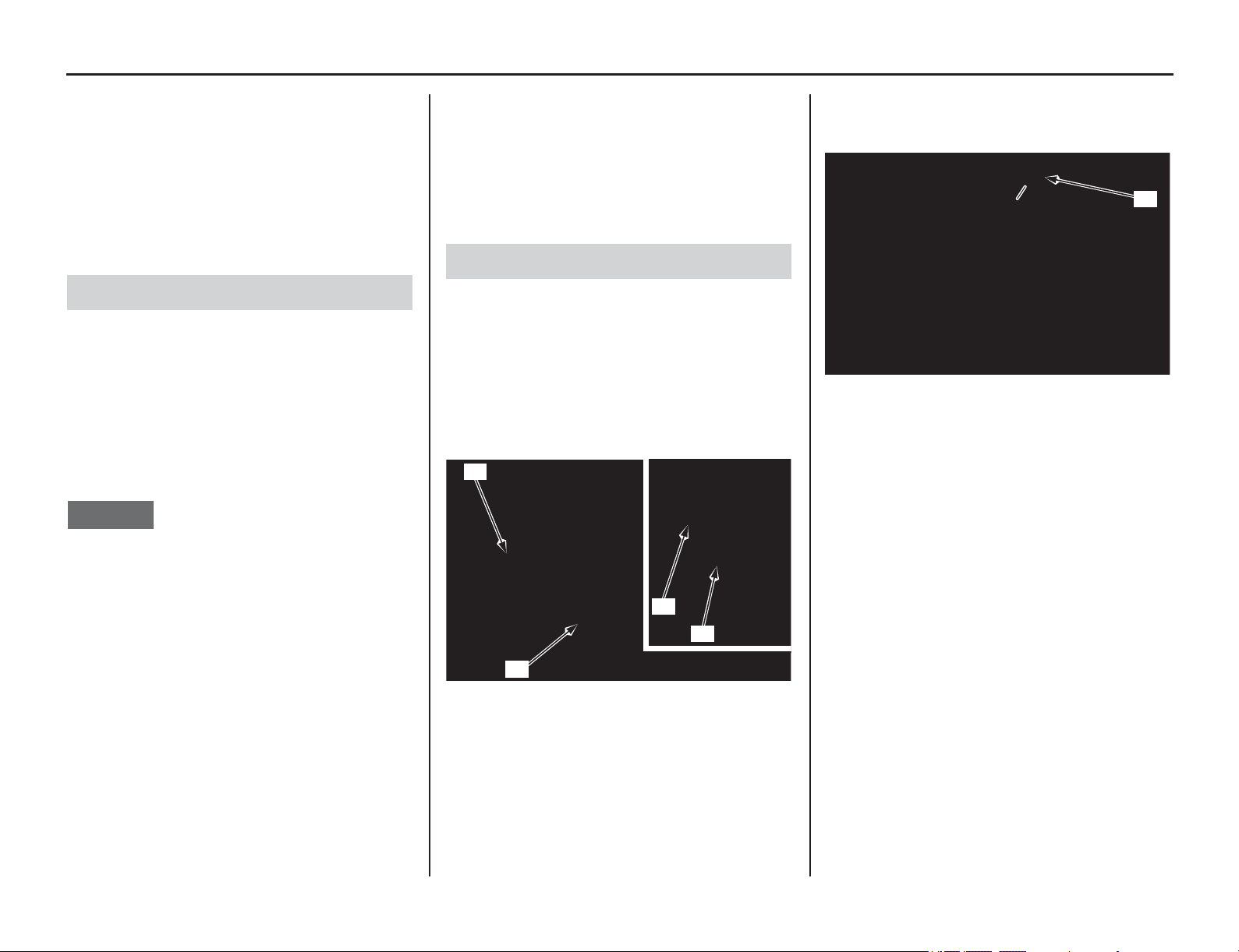
Coolant
72 Servicing Your Honda
Refer to Important Safety Precautions on page 33.
Your motorcycle's
liquid cooling system dissipates
engine heat through the coolant jacket that
surrounds the cylinder and cylinder head.
Maintaining the coolant will allow the cooling
system to work properly and prevent freezing,
overheating, and corrosion.
Use Pro Honda HP Coolant or an equivalent high
quality ethylene glycol antifreeze containing
corrosion protection inhibitors specifically
recommended for use in aluminum engines. Check
the antifreeze container label.
Use only distilled water as a part of the coolant
solution. Water that is high in mineral content or
salt may be harmful to the aluminum engine.
NOTICE
Using coolant with silicate inhibitors may cause
premature wear of the mechanical seal or
blockage of the radiator passages. Using tap
water may cause engine damage.
The factory provides a 50/50 solution of antifreeze
and water in this motorcycle. This coolant solution
is recommended for most operating temperatures
and provides good corrosion protection.
Decreasing the concentration of antifreeze to less
than 40% will not provide proper corrosion
protection.
Increasing the concentration of antifreeze is not
recommended because it decreases cooling system
performance. Higher concentrations of antifreeze
(up to 60%) should only be used to provide
additional protection against freezing.
Check the cooling system frequently during
freezing weather.
Refer to Important Safety Precautions on page 33.
1. With the engine at normal operating
temperature, check the coolant level in the
reserve tank (1). It should be between the
UPPER level (2) and LOWER level (3) marks.
If the reserve tank is empty, or if coolant loss is
excessive, check for leaks and see your dealer
for repair.
2. Remove the reserve tank cap (5). Always add
coolant to the reserve tank. Do not attempt to
add coolant by removing the radiator cap.
3. Add coolant to the reserve tank as require to
bring the coolant level to the UPPER level
mark.
4. Install the reserve tank cap.
Coolant Recommendation
Checking & Adding Coolant
(1) reserve tank (3) LOWER level
(2) UPPER level (4) inspection window
(1)
(4)
(3)
(2)
(5) reserve tank cap
(5)
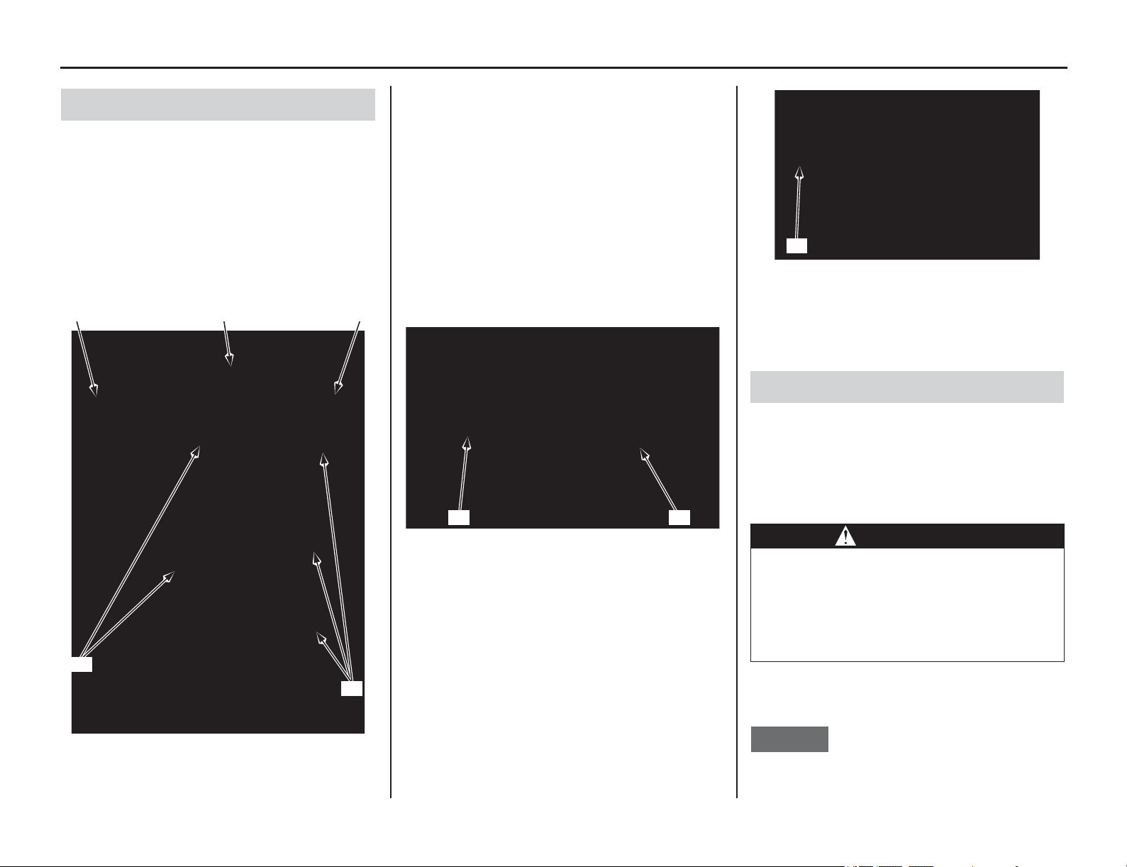
Servicing Your Honda 73
Coolant
1. Check the cooling system for leaks (see an
official Honda Service Manual for
troubleshooting of leaks).
2. Check the radiator hoses (1) for cracks,
deterioration, and radiator hose clamps for
looseness.
3. Check the radiator mount for looseness.
4. Make sure the siphon hose (2) is connected and
not clogged.
5. Check the radiator fins (3) for clogging.
6. Check the bleed hole (4) below the water pump
cover (5) for leakage. Clean away any clogged
dirt or sand, if necessary. Check the bleed hole
of the water pump for signs of seal leakage. If
water leaks through the bleed hole, replace the
mechanical seal. If oil leaks through the bleed
hole, replace the oil seal. Make sure that there
is no continuous coolant leakage from the
bleed hole while operating the engine.
A small amount of coolant weeping from the
bleed hole is normal. See an official Honda
Service Manual or consult your dealer for
replacing the mechanical seal or oil seal.
Both
seals should be replaced at the same time.
7. Check the radiator air passages for clogging
or
damage.
Straighten bent fins (6), and remove insects,
mud or other obstructions with compressed air
or low water pressure.
Replace the radiator if the air flow is restricted
over more than 20% of the radiating surface.
R
adiator should be replaced by your dealer, unless
you have the proper tools and service data and are
mechanically qualified. Refer to an official Honda
Service Manual (page 194).
Refer to Important Safety Precautions on page 33.
Coolant should be replaced by your dealer, unless
you have the proper tools and service data and are
mechanically qualified. Refer to an official Honda
Service Manual (page 194).
To properly dispose of drained coolant, refer to
You & the Environment on page 160.
NOTICE
Improper disposal of drained fluids is harmful to
the environment.
Cooling System Inspection
(1) radiator hoses (3) radiator fins
(2) siphon hose
(2)(3) (3)
(1)
(1)
(4) bleed hole
(5) water pump cover
(4)(5)
(6) fins
Coolant Replacement
WARNING
Removing the radiator cap while the
engine is hot can cause the coolant to
spray out, seriously scalding you.
Always let the engine and radiator cool
down before removing the radiator cap.
(6)

74 Servicing Your Honda
Coolant
1. Remove the radiator cap (1).
2. Fill the system with the recommended coolant
through the filler opening up to filler neck (2).
Use a fresh recommended coolant mixture
(page 72).
3. Remove the reserve tank cap (3) and fill the
reserve tank up to the UPPER level line (4).
4. Bleed air from the system as follows:
• Shift the transmission into neutral. Start the
engine and let it idle 2 -3 minutes.
• Snap the throttle three - four times to bleed
air from the system.
• Stop the engine and, if necessary, add
coolant up to the proper level. Reinstall the
radiator cap.
• Check the level of coolant in the reserve tank
and fill to the UPPER level if it is low.
NOTICE
If the radiator cap is not installed properly, it will
cause excessive coolant loss and may result in
overheating and engine damage.
5. Install the reserve tank cap.
Cooling System Bleed Air
Capacity: 1.31 US qt (1.24 ℓ)
after disassembly
1.20 US qt (1.14 ℓ)
after draining
(1) radiator cap (2) filler neck
(1)
(2)
(3) reserve tank cap (4) UPPER level line
(3)
(4)
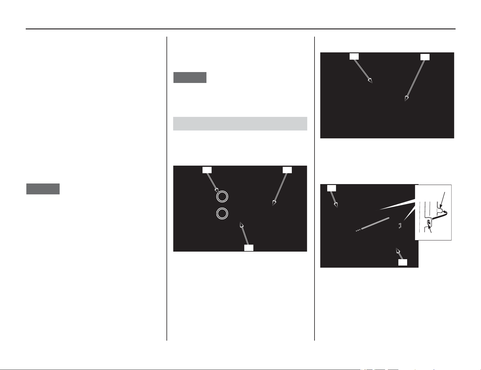
Air Cleaner
Servicing Your Honda 75
Refer to Important Safety Precautions on page 33.
The air cleaner uses polyurethane inner and outer
pieces which can’t be separated.
A dirty air cleaner will reduce engine power.
Proper air cleaner maintenance is very important
for all motorcycle. A dirty, water-soaked, worn-
out
, or defective air cleaner will allow dirt, dust,
mud, and other impurities to pass into the engine.
Service the air cleaner more frequently if you ride
in unusually wet or dusty areas. Your dealer can
help you determine the correct service interval for
your riding conditions.
Your motorcycle' s air cleaner has very specific
performance requirements. Use a new Honda
Genuine air cleaner specified for your model or an
air cleaner of equal quality.
NOTICE
Using the wrong air cleaner may result in
premature engine wear.
Proper air cleaner maintenance can prevent
premature engine wear or damage, expensive
repairs, low engine power, poor gas mileage, and
spark plug fouling.
NOTICE
Improper or lack of proper air cleaner
maintenance can cause poor performance and
premature engine wear.
1. Remove the seat (page 46).
2. Remove the air cleaner lid bolts(1). Unhook
the retainer (2) and remove the air cleaner lid
(3).
3. Remove the air cleaner retaining bolt (4) and
air cleaner assembly(5).
4. Remove the air cleaner element (6) from the air
cleaner holder (7) by releasing the hole (8) of
the air cleaner element from the holder tab (9).
Cleaning
(1) bolts
(2) retainer
(3) air cleaner lid
(3)
(2)
(1)
(4) air cleaner retaining bolt
(5) air cleaner assembly
(6) air cleaner element (8) hole
(7) air cleaner holder (9) holder tab
(4)
(5)
(6)
(8)
(9)
(7)
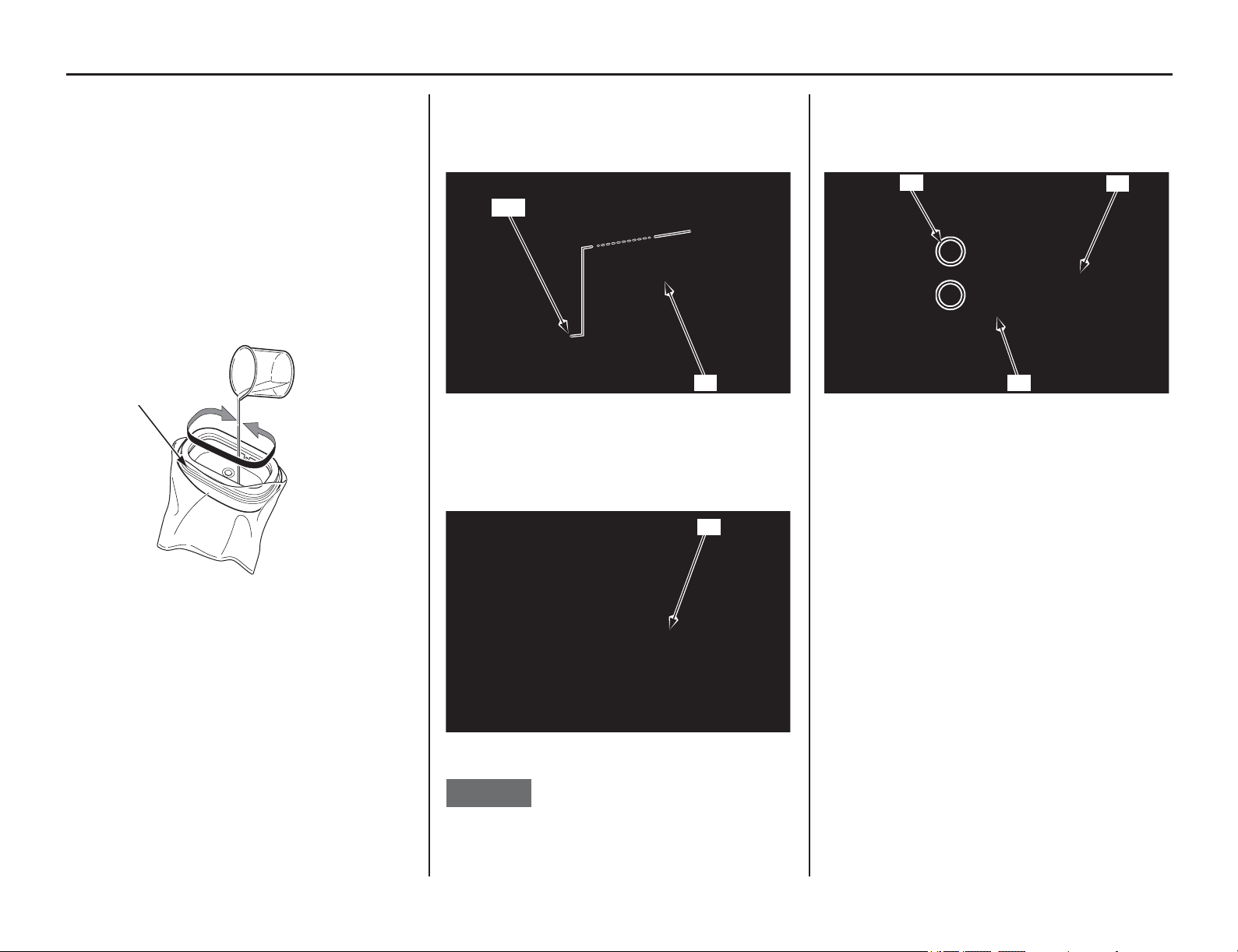
76 Servicing Your Honda
Air Cleaner
5. Wash the air cleaner in clean non-flammable
cleaning solvent such as Pro Honda foam air
filter cleaner. Then wash in hot, soapy water,
rinse well, and allow to dry thoroughly. The air
cleaner element is made in two pieces: inner
and outer, which cannot be separated.
6. Clean the inside of the air cleaner housing.
7. Allow the air cleaner to dry thoroughly. After
drying, apply 1.9 US oz (55 cm
3
) of clean Pro
Honda Foam Air Filter Oil or an equivalent air
cleaner oil from the inside of the element.
Place the element into a plastic bag (10) and
spread the oil evenly by hand.
8. Assemble the air cleaner element and holder.
Install the holder tab in the hole of the air
cleaner element.
9. Apply 0.05 – 0.19 oz (1.5 – 5.5 g) of Pro Honda
Foam Air Filter Sealer or equivalent to the air
cleaner element contact area of the air cleaner
housing.
10. Install the air cleaner assembly (5) into the air
cleaner housing stay (11).
11. Carefully position the sealing flange of the
element to prevent dirt intrusion.
12. Install and tighten the air cleaner retaining bolt
(4) to the specified torque:
1.8 lbf·ft (2.4 N·m, 0.2 kgf·m)
NOTICE
Improper installation of the air cleaner assembly
may allow dirt and dust to enter the engine and
cause rapid wear of the piston rings and cylinder.
13. Install the air cleaner lid (3) onto the air cleaner
housing. Install and tighten the air cleaner lid
bolts (1). Secure the air cleaner lid with the
retainer (2) as shown.
14. Install the seat (page 46).
(10) plastic bag
(10)
(5) air cleaner assembly
(11) air cleaner housing stay
(4) air cleaner retaining bolt
(5)
(11)
(4)
(1) bolts
(2) retainer
(3) air cleaner lid
(3)
(2)
(1)
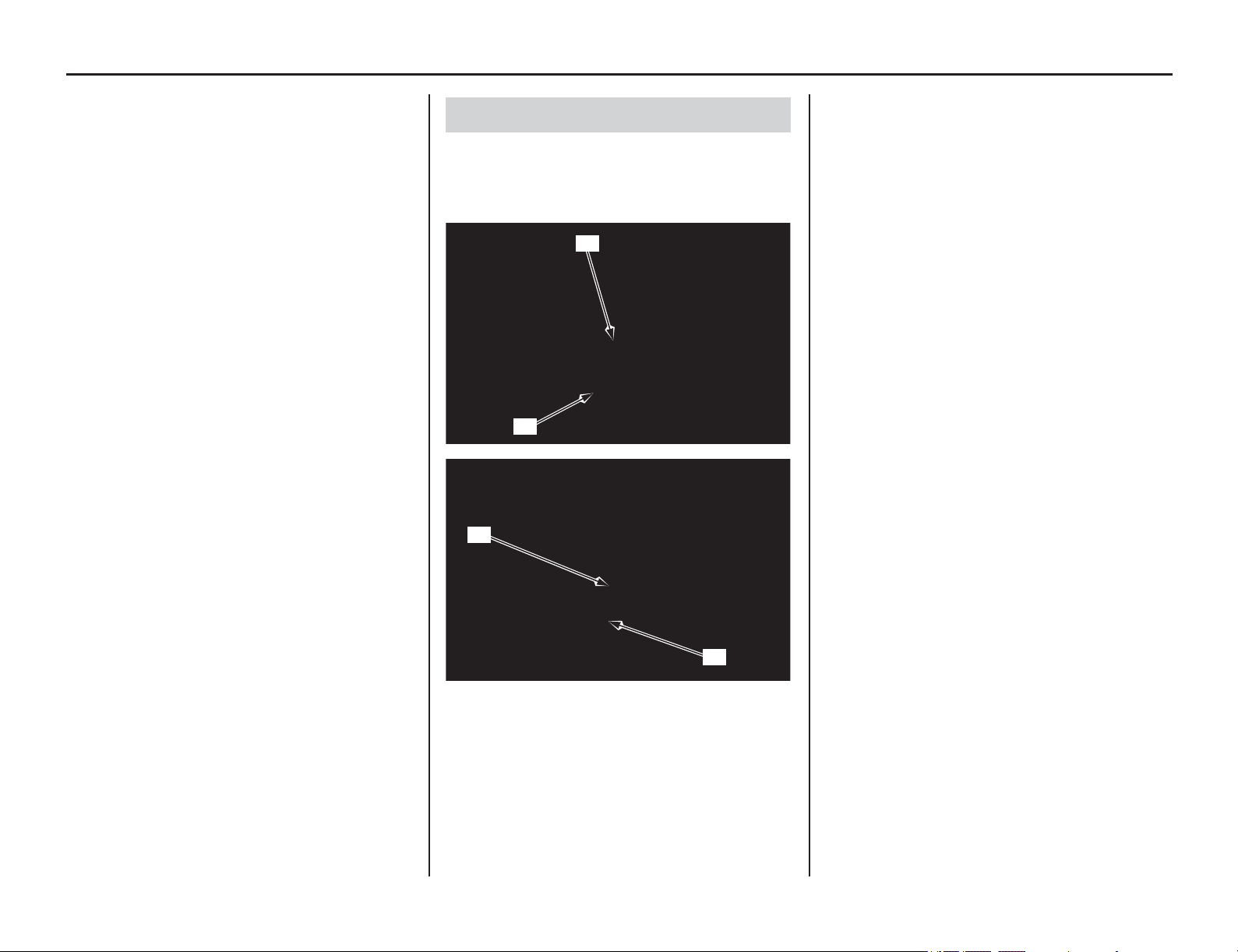
Crankcase Breather
Servicing Your Honda 77
Refer to Important Safety Precautions on page 33.
Service more frequently if your motorcycl
e is
ridden in the rain or often at full throttle.
Service the breather if you can see deposits in the
transparent section of the crankcase breather tube.
If the breather tube overflows, the air filter may
become contaminated with engine oil causing poor
engine performance.
1. Remove the crankcase breather tube plugs (1)
from the crankcase breather tubes (2) and drain
deposits into a suitable container.
2. Reinstall the crankcase breather tube plugs.
Draining
(1) crankcase breather tube plugs
(2) crankcase breather tubes
(2)
(1)
(2)
(1)
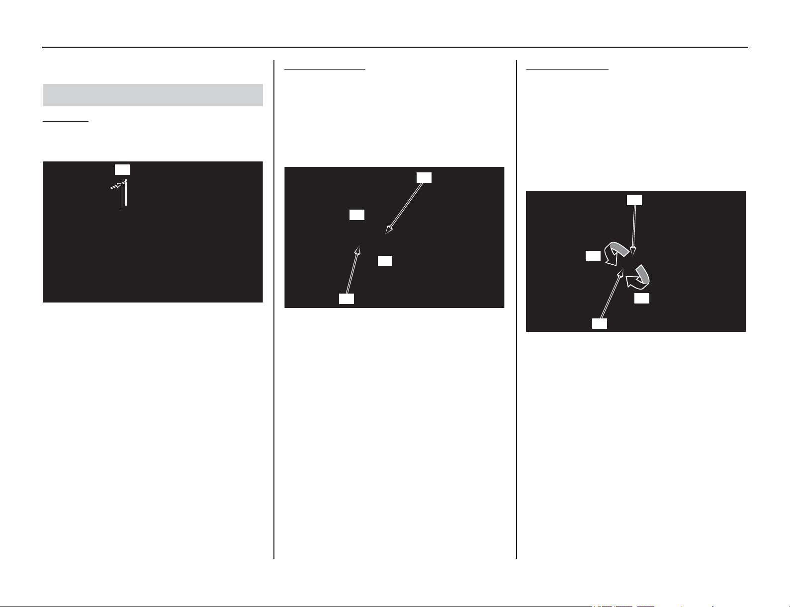
Throttle
78 Servicing Your Honda
Refer to Important Safety Precautions on page 33.
Inspection
Check freeplay (1).
Freeplay: 1/8 – 1/4 in (3 – 6 mm)
If necessary, adjust to the specified range.
Upper Adjustment
Minor adjustments are generally made with the
upper adjuster.
1. Loosen the lock nut (1).
2. Turn the adjuster (2).
Turning the adjuster in direction (–) will
decrease freeplay and turning it in direction (+)
will increase freeplay.
3. Tighten the lock nut securely.
4. After adjustment, check for smooth rotation of
the throttle grip from fully closed to fully open
in all steering positions.
If the adjuster is threaded out near its limit or
the correct freeplay cannot be reached, turn the
adjuster all the way in and back out one turn.
Tighten the lock nut securely.
Make the adjustment with the lower adjuster.
Lower Adjustment
The lower adjuster is used for major freeplay
adjustment, such as after replacing the throttle
cables or removing the throttle body. It is also used
if you cannot get the proper adjustment with the
upper adjuster.
1. Loosen the lock nut (1).
2. Turn the adjuster (2) in direction (–) to
decrease freeplay, and in direction (+) to
increase freeplay.
3. Tighten the lock nut to the specified torque:
3.0 lbf·ft (4.0 N·m, 0.4 kgf·m)
4. Operate the throttle grip to ensure that it
functions smoothly and returns completely.
If you can’t get the freeplay within the specified
range, contact your dealer.
Throttle Freeplay
(1) freeplay
(1)
(1) lock nut (+) increase freeplay
(2) adjuster (–) decrease freeplay
(2)
(1)
(+)
(–)
(1) lock nut (+) increase freeplay
(2) adjuster (–) decrease freeplay
(1)
(2)
(–)
(+)
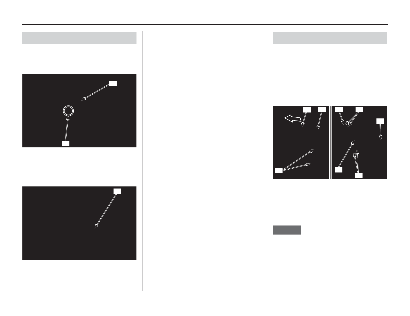
Servicing Your Honda 79
Throttle
1. Check that the throttle assembly is positioned
properly (the end of the throttle housing (1) is
aligned with the paint mark (2) on the
handlebar) and the securing bolts are tight.
2. Check for smooth rotation of the throttle (3)
from fully open to fully closed in all steering
positions. If there is a problem, see your dealer.
3. Inspect the condition of the throttle cables
from the throttle grip down to the throttle body.
If the cable is kinked or chafed, have it
replaced.
4. Check the cables for tension or stress in all
steering positions.
5. Lubricate the cables with a commercially
available cable lubricant.
Check for smooth rotation of the throttle. If
necessary, apply multi-purpose grease to sliding
surface of the throttle cable ends.
1. Slide the dust cover (1).
2. Remove the throttle housing bolts (2).
3. Remove the throttle housing (3) from the
throttle pipe (4).
4. Thoroughly lubricate the throttle cable ends (5)
with multi-purpose grease.
5. Install the throttle housing, then tighten the
throttle housing bolts to the specified torque:
7 lbf·ft (10 N·m, 1.0 kgf·m)
NOTICE
Align the lugs (6) of the wire guide with the
grooves (7) of the throttle housing.
6. Install the dust cover in reverse order.
If the throttle operation is not smooth, replace the
throttle cable.
Be sure the throttle returns freely from fully open
to fully closed automatically, in all steering
positions.
Throttle Inspection
(1) throttle housing
(2) paint mark
(3) throttle
(1)
(2)
(3)
Throttle Cable Lubrication
(1) dust cover (5) throttle cable ends
(2) housing bolts (6) lugs
(3) throttle housing (7) grooves
(4) throttle pipe
(2)
(1)
(3)
(6)
(4)
(7)
(7)
(5)
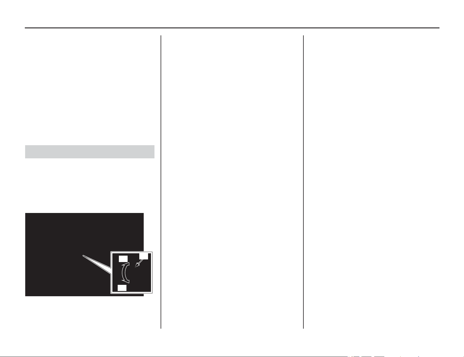
Engine Idle Speed
80 Servicing Your Honda
Engine Idle Speed
Refer to Important Safety Precautions on page 33.
Remember, idle speed adjustment is not a “cure
-
all” for other problems in your engine’s PGM-FI
system. Adjusting the idle speed will not
compensate for a fault elsewhere.
The engine must be at normal operating
temperature for accurate idle speed adjustment.
When pushed in, the fast idle knob acts as the idle
adjustment screw.
Turning it counterclockwise results in a faster/
higher idle speed.
Turning it clockwise results in a slower/lower idle
speed.
1. If the engine is cold, start it and warm it up 3
minutes. Then shut it off.
2. Connect a tachometer to the engine.
3. Shift the transmission into neutral. Start the
engine.
4. Adjust idle speed with the fast idle knob (1).
Idle speed: 1,800 ± 100 rpm
Idle Speed Adjustment
(1) fast idle knob
(+) increase
(–) decrease
(1)
(–)
(+)
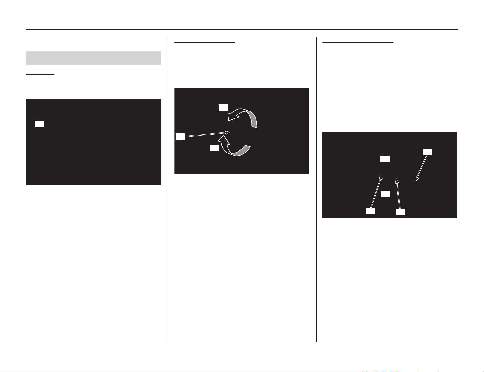
Clutch System
Servicing Your Honda 81
Refer to Important Safety Precautions on page 33.
Inspection
Check freeplay (1).
Freeplay: 3/8 – 13/16 in (10 – 20 mm)
If necessary, adjust to the specified range.
Improper freeplay adjustment can cause premature
clutch wear.
Make sure to adjust the clutch lever freeplay after
the clutch cable is disconnected.
Cable End Adjustment
Minor adjustments are generally made with the
clutch cable end adjuster.
Turning the clutch cable end adjuster (1) in
direction (+) will increase freeplay and turning it in
direction (–) will decrease freeplay.
If the adjuster is threaded out near its limit or the
correct freeplay cannot be reached, turn the
adjuster all the way in and back out five turns and
make the adjustment with the integral cable
adjuster.
Integral Cable Adjustment
The integral cable adjuster is used if the cable end
adjuster is threaded out near its limit — or the
correct freeplay cannot be obtained.
1. Release the dust cover (1).
2. Turn the cable end adjuster in direction (+)
until it seats lightly and then turn it out five
turns.
3. Loosen the lock nut (2).
4. Turn the integral cable adjuster (3) to obtain
the specified freeplay.
5. Tighten the lock nut. Check the freeplay.
6. Start the engine, pull the clutch lever in, and
shift into gear. Make sure the engine does not
stall and the motorcycle does not creep.
Gradually release the clutch lever and open the
throttle. Your motorcycle should move
smoothly and accelerate gradually.
If you can’t get proper adjustment, or the clutch
does not work properly, the cable may be kinked or
worn, or the clutch discs may be worn.
Inspect the clutch discs and plates (page 84).
Clutch Lever Freeplay
(1) freeplay
(1)
(1) clutch cable end adjuster
(+) increase freeplay
(–) decrease freeplay
(1)
(–)
(+)
(1) dust cover (+) increase freeplay
(2) lock nut (–) decrease freeplay
(3) integral cable adjuster
(1)
(–)
(+)
(2)
(3)
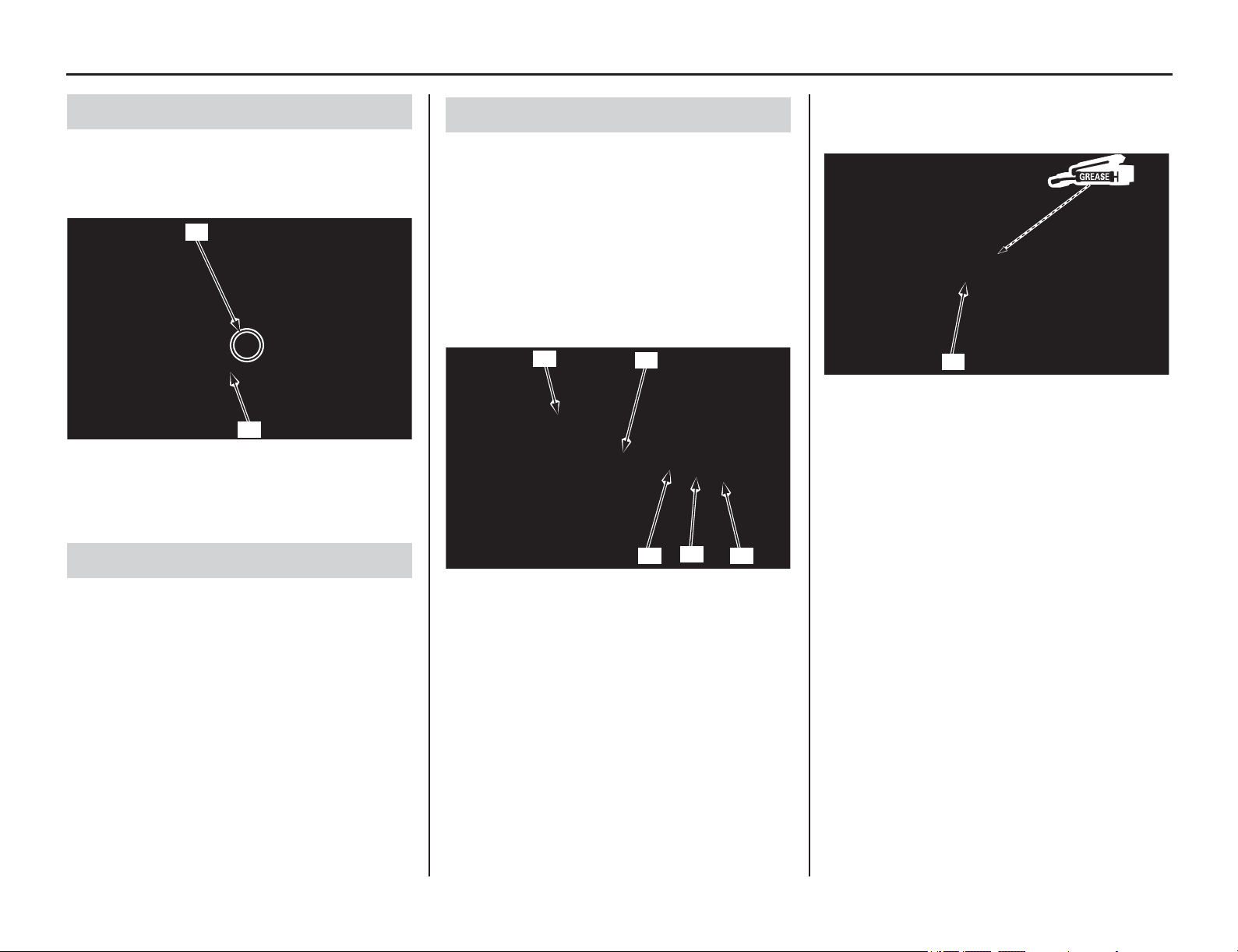
Clutch System
82 Servicing Your Honda
• Check that the clutch lever assembly is
positioned properly (the end of the holder (1) is
aligned with the paint mark (2) on the
handlebar) and the securing bolts are tight.
• Check the clutch cable for kinks or signs of
wear. If necessary, have it replaced.
1. Check for smooth clutch lever operation. If
necessary, lubricate the clutch lever pivot bolt
sliding surface with grease and/or clutch cable
with commercially available cable lubricant.
2. Check the clutch cable for deterioration, kinks,
or damage.
Check for smooth clutch lever operation. If
necessary, apply multi-purpose grease to sliding
surface of the clutch cable ends.
1. Release the dust cover (1).
2. Turn the adjuster (2) and remove the clutch
cable (3).
3. Disconnect the clutch cable end (4) from the
clutch lever (5).
4. Thoroughly lubricate the clutch cable end with
multi-purpose grease.
5. Connect the clutch cable end to the lever.
6. Install the clutch cable and turn the adjuster.
7. Remove the clutch cable end adjuster (6).
8. Apply multi-purpose grease to the clutch cable
end adjuster inside surface.
9. Recheck clutch lever freeplay and adjust as
necessary (page 81).
If the clutch lever operation is not smooth, replace
the clutch cable.
Other Inspections
(1) holder
(2) paint mark
Clutch Operation
(1)
(2)
Clutch Cable Lubrication
(1) dust cover (4) clutch cable end
(2) adjuster (5) clutch lever
(3) clutch cable
(1)
(2)
(3)
(4)
(5)
(6) clutch cable end adjuster
(6)
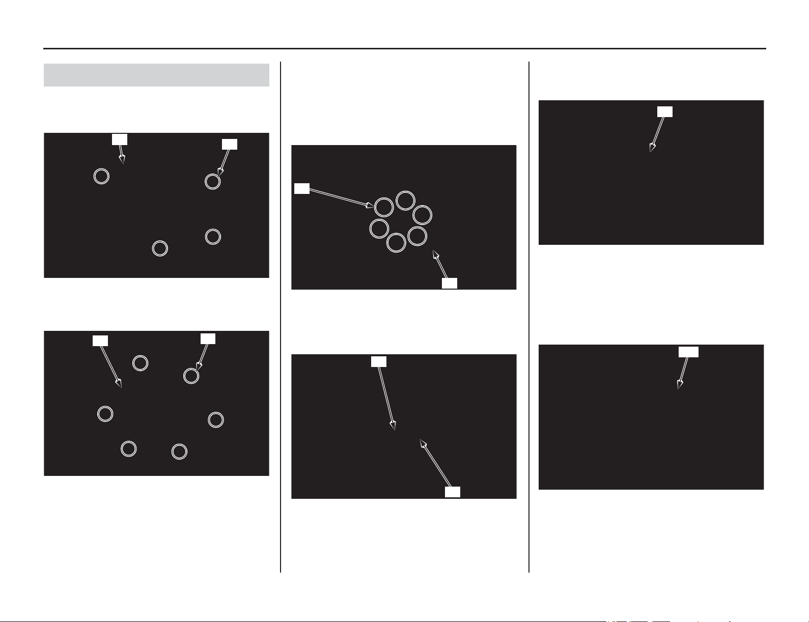
Servicing Your Honda 83
Clutch System
1. Drain the engine oil (page 70).
2. Remove the four right crankcase over cover
bolts (1) and over cover (2).
3. Remove the six clutch cover bolts (3) and
clutch cover (4).
4. Remove the six clutch spring bolts and springs
(5).
Loosen the bolts in a crisscross pattern in two or
three progressive steps.
5. Remove the clutch pressure plate (6).
6. Remove the clutch lifter (7) first, then remove
the clutch lifter rod (8).
7. Check the operation of the thrust bearing (9)
built in clutch lifter with your finger. The
bearing should turn smoothly and quietly.
If the operation is not smooth, refer to an official
Honda Service Manual (page 194) for bearing
disassembly or see your dealer.
8. Remove the seven clutch discs, six clutch
plates, judder spring and spring seat (10).
Clutch Disc/Plate Removal
(1) bolts (2) over cover
(3) clutch cover bolts (4) clutch cover
(1)
(2)
(3)
(4)
(5) clutch spring bolts and springs
(6) clutch pressure plate
(7) clutch lifter (8) clutch lifter rod
(6)
(5)
(8)
(7)
(9) thrust bearing
(10) clutch discs, clutch plates, judder spring and spring
seat
(9)
(10)
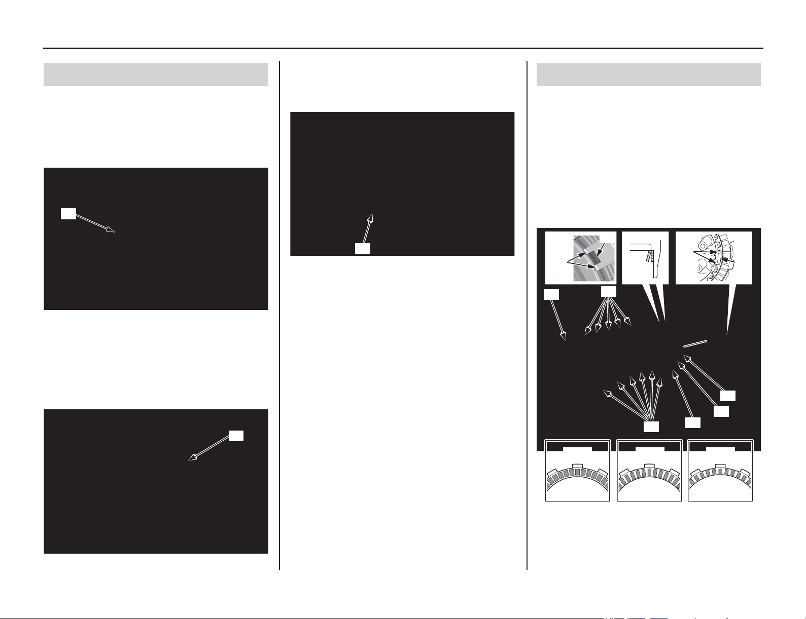
84 Servicing Your Honda
Clutch System
• Replace the clutch discs (1) if they show signs of
scoring or discoloration.
Measure the thickness of each clutch disc.
Service Limit: 0.112 in (2.85 mm)
Replace the clutch discs and clutch plates as a
set.
• Check the clutch plates (2) for excessive
warpage or discoloration.
Check the plate warpage on a surface plate using
a feeler gauge.
Service Limit: 0.006 in (0.15 mm)
Replace the clutch discs and plates as a set.
• Check the clutch springs (3) for wear or damage.
Measure the thickness of each clutch spring.
Service Limit: 1.79 in (45.5 mm)
Replace the clutch spring as a set.
• If you feel the clutch slippage when replacing the
clutch discs and plates, replace the clutch
springs.
1. Install the spring seat (1) and judder spring (2)
onto the clutch center as shown.
Coat the clutch discs with engine oil.
2. Install the clutch disc A (larger I.D. disc) (3) onto
the clutch outer.
Stack the six clutch plates (4), five clutch discs B
(5)
alterna
tely while aligning the lugs (6) of the
clutch center with the groove (7) of the clutch
plates as shown.
Install the clutch disc C (8) by aligning its tabs (9)
with the shallow slots (10) of the clutch outer.
Clutch Disc/Plate/Spring Inspection
(1) clutch discs
(2) clutch plates
(1)
(2)
(3) clutch springs
(3)
Clutch Disc/Plate Installation
(1) spring seat (6) lugs
(2) judder spring (7) groove
(3) clutch disc A (8) clutch disc C
(4) clutch plates (9) tabs
(5) clutch discs B (10) shallow slots
(8)
disc C disc B disc A
(5)
(6)
(7)
(3)
(2)
(1)
(4)
(10)
(9)
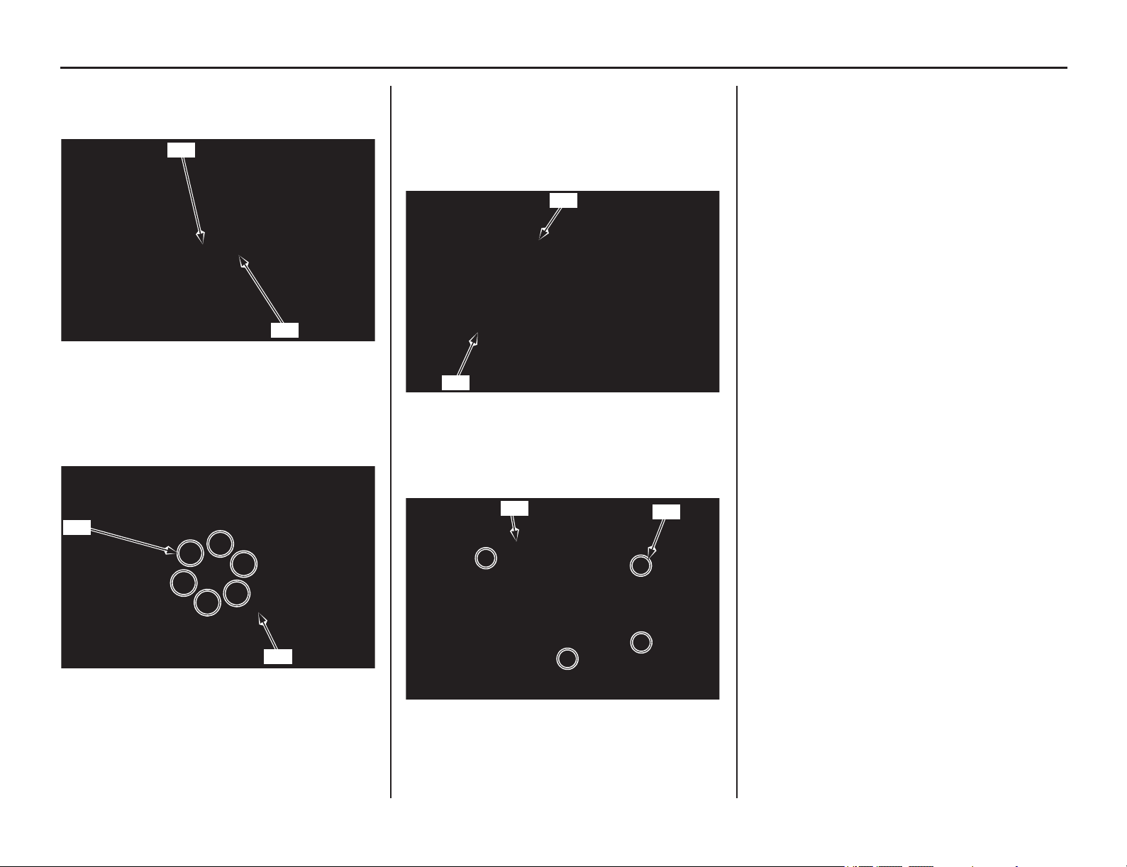
Servicing Your Honda 85
Clutch System
3. Insert the clutch lifter rod (11) into the
mainshaft.
4. Install the clutch lifter (12) onto the rod.
5. Install the clutch pressure plate (13).
6. Install the six clutch springs and bolts (14).
7. Tighten the bolts in a crisscross pattern in two
or three steps to the specified torque:
9 lbf·ft (12 N·m, 1.2 kgf·m)
8. Apply engine oil to a new O-ring (15) and
install it in the groove of the clutch cover (16).
9. Install the cover by tightening the six cover
bolts in a crisscross pattern in two or three
steps to the specified torque:
7 lbf·ft (10 N·m, 1.0 kgf·m)
10. Install the right crankcase over cover (17) and
tighten the four right crankcase over cover
bolts (18).
11. Pour recommended engine oil to the specified
level (page 70).
(11) clutch lifter rod (12) clutch lifter
(13) clutch pressure plate
(14) clutch spring bolts and springs
(11)
(12)
(14)
(13)
(15) O-ring (new)
(16) clutch cover
(17) over cover (18) bolts
(15)
(16)
(17)
(18)
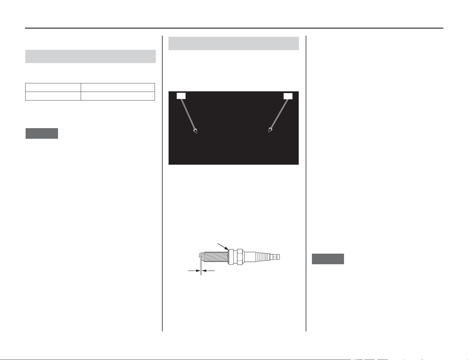
Spark Plug
86 Servicing Your Honda
Spark Plug
Refer to Important Safety Precautions on page 33.
The recommended standard spark plug is
satisfactory for most racing conditions.
Use only the recommended type of spark plugs in
the recommended heat range.
NOTICE
Using a spark plug with an improper heat range or
incorrect reach can cause engine damage.
Using a non-resistor spark plug may cause
ignition problems.
This motorcycle uses a spark plug that has an
iridium tip in the center electrode and a platinum
tip in the side electrode.
Be sure to observe the following when servicing
the spark plug.
• Do not clean the spark plug. If an electrode is
contaminated with accumulated objects or dirt,
replace the spark plug with a new one.
• To check the spark plug gap, use only a “wire-
type feeler gauge.” To prevent damaging the
iridium tip of the center electrode and platinum
tip of the side electrode, never use a “leaf-type
feeler gauge.”
• Do not adjust the spark plug gap. If the gap is out
of specification, replace the spark plug with a
new one.
1. Remove the seat and fuel tank (pages 46, 48).
2. Disconnect the spark plug cap (1).
3. Clean any dirt from around the spark plug
base.
4. Remove the spark plug (2).
5. Check the electrodes for wear or deposits, the
sealing gasket (3) for damage, and the insulator
for cracks. Replace if you detect them.
6. Check the spark plug gap (4), using a wire-type
feeler gauge. If the gap is out of specifications,
replace the plug with a new one.
The recommended spark plug gap is:
0.031 – 0.035 in (0.8 – 0.9 mm)
7. To obtain accurate spark plug readings,
accelerate up to speed on a straightaway.
Press and hold the engine stop button and
disengage the clutch by pulling the lever in.
Coast to a stop, then remove and inspect the
spark plug. The porcelain insulator around the
center electrode should appear tan or medium
gray.
If you’re using a new plug, ride for 10 – 15 minutes
before taking a plug reading; a brand-new plug will
not color initially.
If the electrodes appear burnt, or the insulator is
white or light gray (lean) or the electrodes and
insulator are black or fouled (rich), there is a
problem elsewhere (page 153).
Check the PGM-FI system and ignition timing.
8. With the sealing gasket attached, thread the
spark plug in by hand to prevent cross-
threading.
9. Tighten the spark plug.
• If the old plug is good:
1/12 turn after it seats.
• If installing a new plug, tighten it twice to
prevent loosening:
a) First, tighten the plug:
1/4 turn after it seats.
b) Then loosen the plug.
c) Next, tighten the plug again:
1/12 turn after it seats.
When using a torque wrench, tighten the spark
plug to the specified torque:
16 lbf·ft (22 N·m, 2.2 kgf·m)
NOTICE
An improperly tightened spark plug can damage
the engine. If a plug is too loose, the piston may be
damaged. If a plug is too tight, the threads may be
damaged.
10. Connect the spark plug cap. Take care to avoid
pinching any cables or wires.
11. Install the fuel tank and seat (pages 46, 50).
Spark Plug Recommendation
Standard SILMAR9A – 9S (NGK)
Optional SILMAR10A – 9S (NGK)
Spark Plug Inspection & Replacement
(1) spark plug cap (2) spark plug
(3) sealing gasket
(4) spark plug gap
(1)
(2)
(3)
(4)
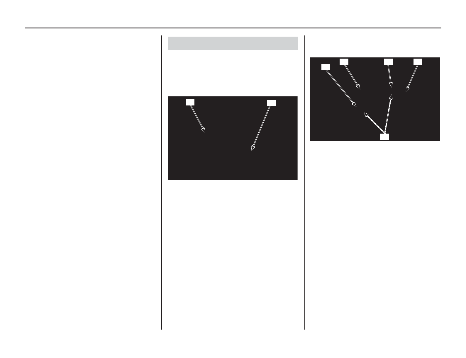
Valve Clearance
Servicing Your Honda 87
Refer to Important Safety Precautions on page 33.
Excessive valve clearance will cause noise and
eventual
engine damage. Little or no clearance will
prevent the valve from closing and cause valve
damage and power loss. Check valve clearance
when the engine is cold at the intervals specified in
the Maintenance Schedule (pages 36, 37).
The checking or adjusting of the valve clearance
should be performed while the engine is cold.
The valve clearance will change as engine
temperature rises.
Before inspection, clean the engine thoroughly to
keep dirt from entering the engine.
1. Remove the seat and fuel tank (pages 46, 48).
2. Disconnect the breather tube (1) and spark
plug cap (2).
3. Remove the cylinder head cover socket bolts
(3), rubber seals (4), cylinder head cover (5)
and spark plug hole packing (6).
Cylinder Head Cover Removal
(1) breather tube (2) spark plug cap
(2)
(1)
(3) cylinder head cover socket bolts
(4) cylinder head cover rubber seals
(5) cylinder head cover
(6) spark plug hole packing
(5)(6)
(4)
(3)
(3)
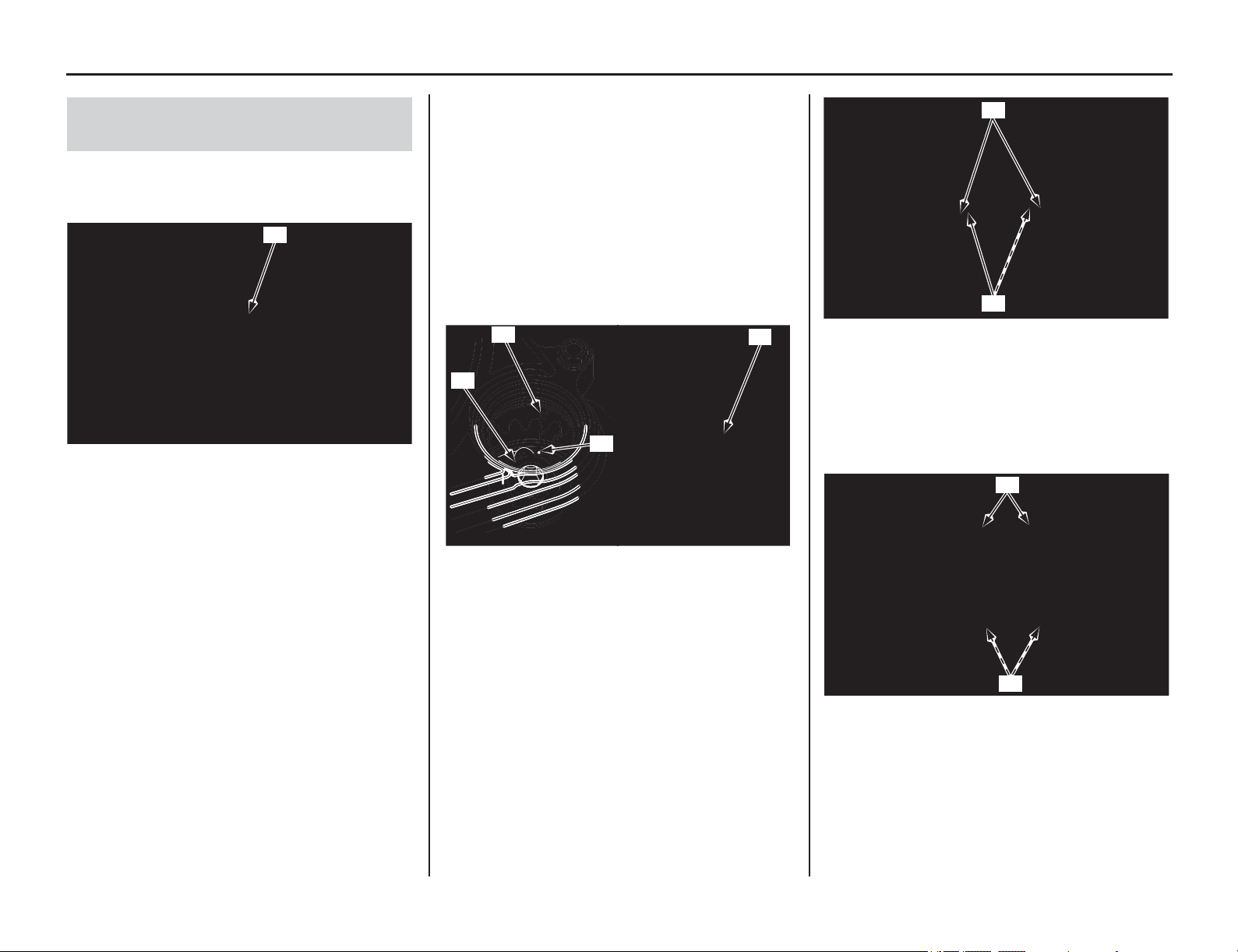
88 Servicing Your Honda
Valve Clearance
1. Remove the right crankcase over cover
(page 83).
2. Remove the crankshaft hole cap (1).
3. Remove the spark plug (page 86).
4. Remove the cylinder head cover (page 87).
5. Rotate the crankshaft by turning the primary
drive gear bolt (2) clockwise until “T” mark (3)
on the primary drive gear aligns with the index
mark (4) on the clutch cover. In this position,
the piston may either be on the compression or
exhaust stroke at TDC. If the primary drive
gear passed the “T” mark, rotate the primary
drive gear bolt clockwise again and align the
“T” mark with the index mark.
Make sure that the decompressor weight (5) is
upper position.
6. Check the timing marks (6) on the cam
sprocket aligns with the camshaft holder
mating surface (7) of the cylinder head.
7. The inspection must be made when the piston
is at the top of the compression stroke when
both the intake and exhaust valves are closed.
This condition can be determined by moving
the rocker arms (8).
Positioning At TDC On The
Compression Stroke
(1) crankshaft hole cap
(1)
(2) primary drive gear bolt
(3) “T” mark
(4) index mark
(5) decompressor weight
(2)
(3)
(4)
(5)
crankshaft side: camshaft side:
(6) timing marks
(7) camshaft holder mating surface
(8) rocker arms
(6)
(7)
(8)
(8)
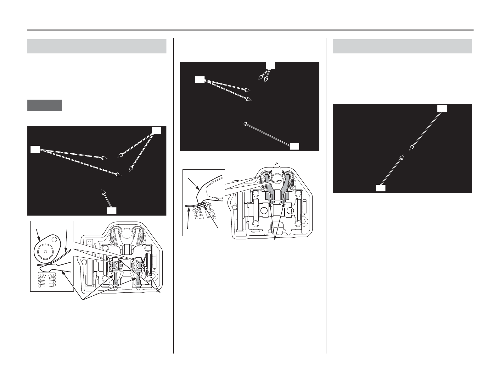
Valve Clearance
(cont’d)
Servicing Your Honda 89
1. Set the piston at TDC on the compression
stroke (page 88).
2. Measure the intake valve clearances by
inserting a feeler gauge (1) between the intake
rocker arms (2) and camshaft cam lobes (3).
NOTICE
Be careful not to damage the intake rocker arms.
Valve Clearance:
3. Measure the exhaust valve clearances by
inserting a feeler gauge (1) between the
exhaust rocker arms (4) and shims (5).
Valve Clearance:
If intake valve clearance and exhaust valve
clearance need adjustment, see Camshaft Removal
(this page) and select the correct shim for each
valve.
1. Record the intake valve and exhaust valve
clearances (this page).
Make sure the piston is at TDC on the
compression stroke (page 88).
2. Remove the cam chain tensioner lifter cover
bolt (1) and sealing washer (2).
Valve Clearance Inspection
(1) feeler gauge (3) camshaft cam lobes
(2) intake rocker arms
IN: 0.004 ± 0.001 in (0.11 ± 0.03 mm)
(2)
(1)
(3)
(3) (1)
(3)
(2)
(1) feeler gauge (5) valve shims
(4) exhaust rocker arms
EX: 0.011 ± 0.001 in (0.28 ± 0.03 mm)
(1)
(4)
(5)
(5)
(1)
(4)
(5)
(4)
Camshaft Removal
(1) cam chain tensioner lifter cover bolt
(2) sealing washer
(1)
(2)
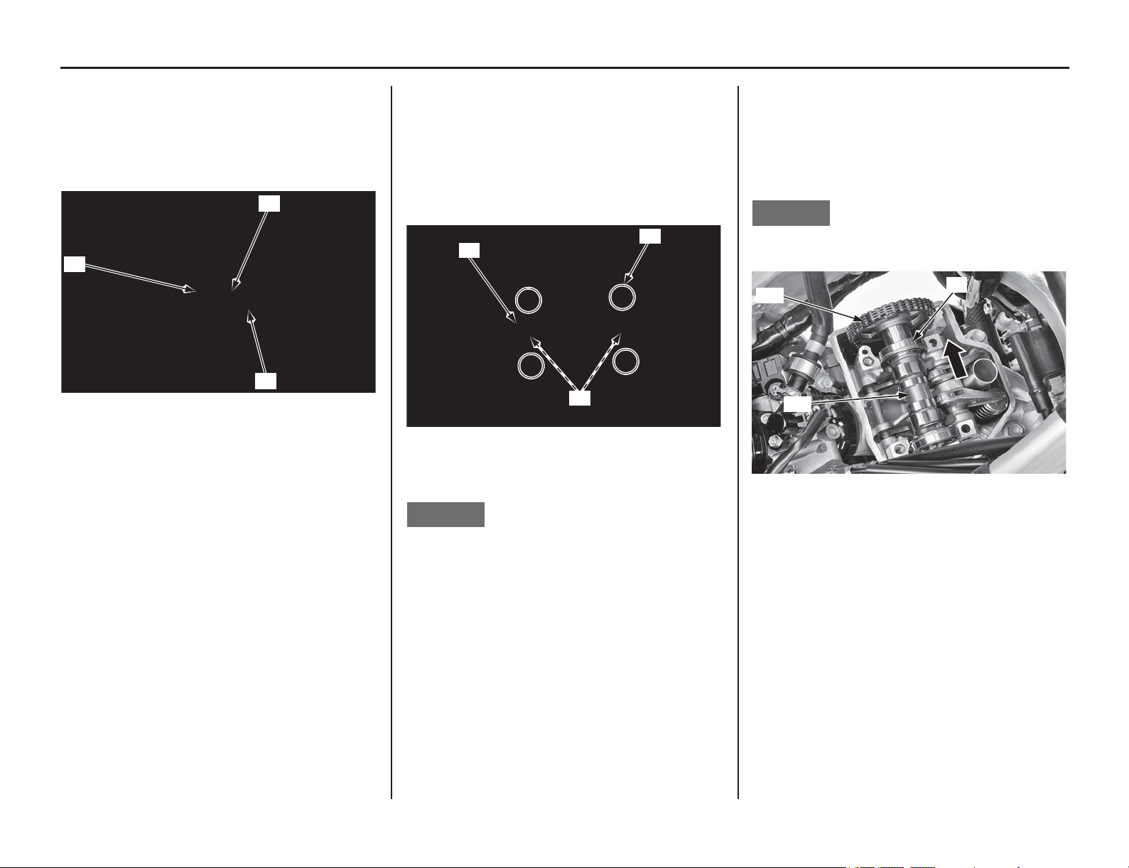
90 Servicing Your Honda
Valve Clearance
3. Insert the tensioner stopper (3) into the cam
chain tensioner lifter (4).
Turn the tensioner stopper clockwise and lock
the cam chain tensioner lifter by pushing the
handle (5) to the cam chain tensioner lifter.
• Tensioner stopper 07AMG-001A100
4. Check the piston is at TDC on the compression
stroke (page 88).
Loosen the camshaft holder bolts (6) in a
crisscross pattern in two or three steps.
Remove the camshaft holder bolts, camshaft
holder (7) and set rings (8).
5. As you remove the camshaft holder, set rings
may be sticking in the camshaft holder.
NOTICE
Do not let the set rings fall into the crankcase.
If the set rings are remained on the camshaft
holder, remove the set rings carefully.
6. Slide the left camshaft bearing (9) and remove
the camshaft (10) by removing the cam chain
(11).
Suspend the cam chain with a piece of wire to
prevent the chain from falling into the crankcase.
NOTICE
Do not let the cam chain fall into the crankcase.
(3) tensioner stopper
(4) cam chain tensioner lifter
(5) handle
(4)
(5)
(3)
(6) camshaft holder bolts
(7) camshaft holder
(8) set rings
(8)
(6)
(7)
(9) left camshaft bearing
(10) camshaft
(11) cam chain
(10)
(11)
(9)
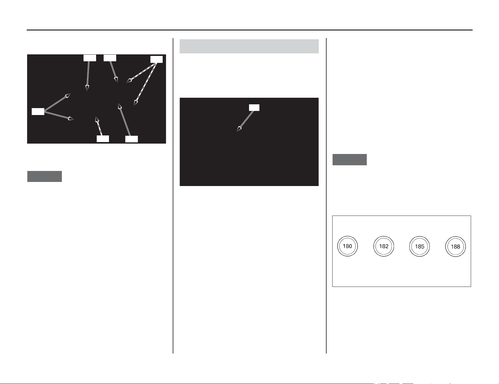
Servicing Your Honda 91
Valve Clearance
7. Lift the rocker arms (12) up and remove the
shims (13).
NOTICE
Be careful not to damage the intake rocker arms.
Do not let the shims fall into the crankcase.
Do not clean the intake rocker arms using a
commercially available compound cleaner.
1. Measure the shim thickness with a micrometer
and record it.
Seventy-three different shims (1) are available
in 0.025 mm thickness intervals, from 1.200
mm (the thinnest) to 3.000 mm (the thickest).
2. Calculate the new shim thickness using the
equation below.
A = (B – C) + D
A: New shim thickness
B: Recorded valve clearance
C: Specified valve clearance
D: Old shim thickness
• Make sure of the correct shim thickness by
measuring the shim with a micrometer.
• Reface the exhaust valve seat if carbon deposits
result in a calculated dimension of over 3.000
mm.
NOTICE
Do not lap the intake valves. They are titanium and
have a thin oxide coating. Lapping will damage
this coating.
If a calculated dimension is out of specifications,
have your motorcycle inspected by your dealer.
(12) rocker arms
(13) shims
(13) (12)
(12)
(12)
(13)
(13)
Shim Selection
(1) shim
(1)
1.80 mm 1.825 mm 1.85 mm
1.875 mm
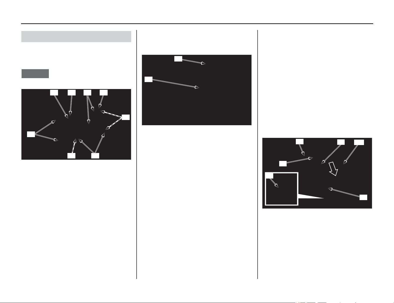
92 Servicing Your Honda
Valve Clearance
1. Lift the rocker arms (1) up and install the
newly selected shims (2) on the valve spring
retainers (3).
NOTICE
Do not let the shims fall into the crankcase.
2. Check the operation of the plunger (4) by
turning the decompressor weight (5) with your
finger. The plunger should be retracted and
protruded smoothly.
If the operation is not smooth, refer to an official
Honda Service Manual (page 194) for
decompressor disassembly or see your dealer.
3. Make sure the piston is at TDC on the
compression stroke (page 88).
4. Apply molybdenum disulfide oil (a mixture of
1/2 engine oil and 1/2 molybdenum disulfide
grease containing more than 3% molybdenum
disulfide additive Moly Paste 77) to the
following parts.
– camshaft cam lobes
– plunger whole surface
5. Install the camshaft (6) onto the cylinder head
with the decompressor weight (5) facing up as
illustrated below.
6. Install the cam chain (7) over the cam sprocket
(8).
While holding the left camshaft bearing (9) to
the left fully, install the camshaft (6) onto the
cylinder head (10) and slide the left camshaft
bearing to the right fully.
Camshaft Installation
(1) rocker arms (3) valve spring retainers
(2) shims
(1)
(1)(2) (3) (3)
(3)(2)
(2)
(4) plunger
(5) decompressor weight
(5)
(4)
(5) decompressor weight (8) cam sprocket
(6) camshaft (9) left camshaft bearing
(7) cam chain (10) cylinder head
(7)
(8)
(5)
(9)
(10)
(6)
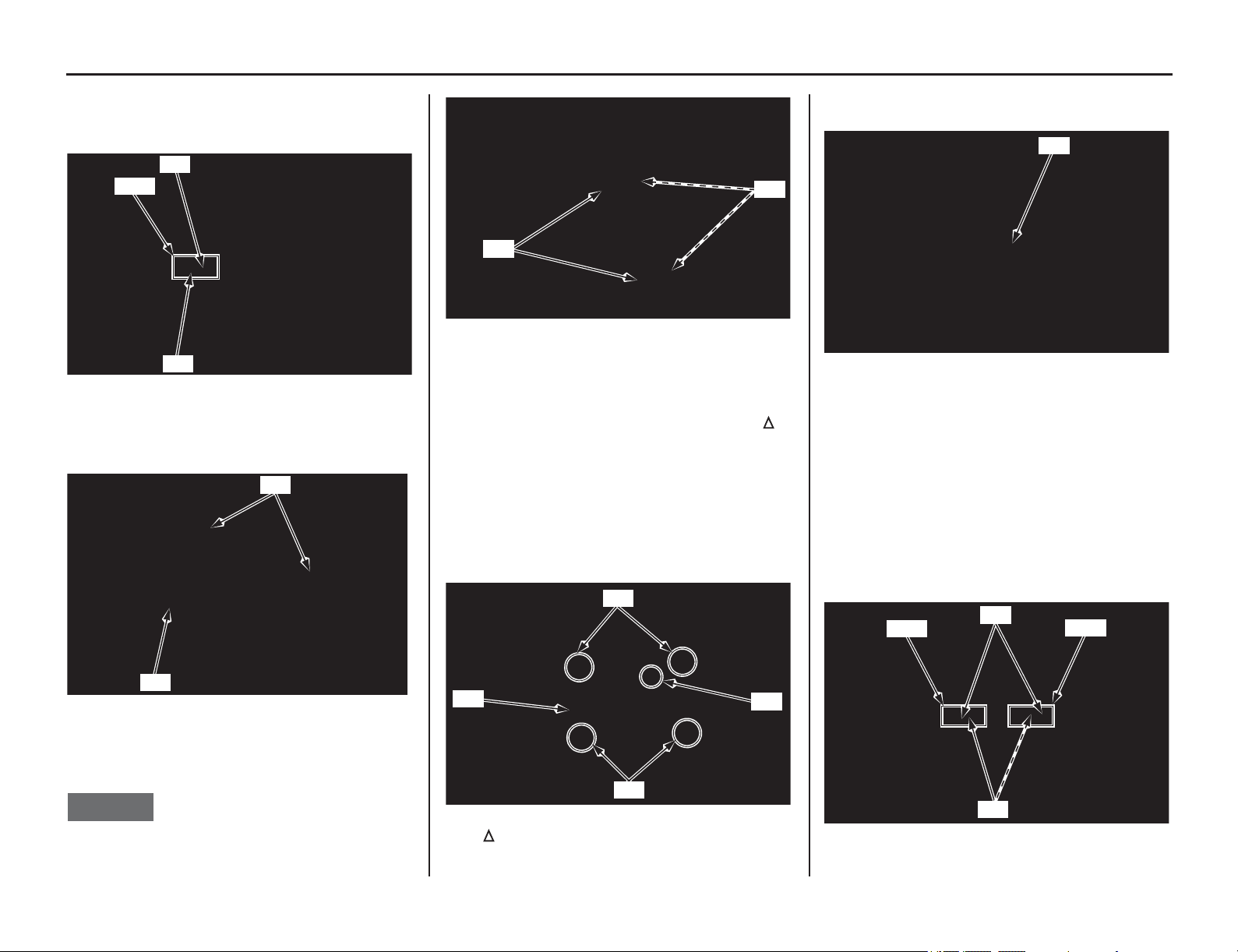
Servicing Your Honda 93
Valve Clearance
7. Make sure that the timing mark (11) on the cam
sprocket aligns with the camshaft holder
mating surface (12) of the cylinder head.
8. Make sure that the dowel pins (13) are installed
into the camshaft holder (14).
9. Install the set rings (15) on the camshaft
bearing grooves (16).
NOTICE
Do not let the set rings fall into the crankcase.
10. Apply engine oil to the camshaft holder bolt
threads.
Install the camshaft holder (17) with the “ ”
mark (18) facing forward.
Install the camshaft holder bolts (19) (20) and
tighten the camshaft holder bolts to the
specified torque:
11 lbf·ft (15 N·m, 1.5 kgf·m)
Tighten the camshaft holder bolts in a crisscross
pattern in two or three steps.
11. Remove the tensioner stopper (21) from the
cam chain tensioner lifter.
12. Make sure that the piston is at TDC on the
compression stroke (page 88).
Check that the timing mark (11) on the cam
sprocket aligns with the camshaft holder
mating surface (12) of the cylinder head.
If the timing mark doesn’t align with the camshaft
holder mating surface, insert the tensioner stopper
into the cam chain tensioner lifter (page 90) and
then remove the cam chain and realign the timing
mark.
(11) timing mark
(12) camshaft holder mating surface
(13) dowel pins (14) camshaft holder
(11)
Align
(12)
(13)
(14)
(15) set rings
(16) camshaft bearing grooves
(17) camshaft holder (19) camshaft holder bolts (long)
(18) “ ” mark
(20) camshaft holder bolts (short)
(15)
(16)
(20)
(19)
(18)
(17)
(21) tensioner stopper
(11) timing mark
(12) camshaft holder mating surface
(21)
Align
(12)
(11)
Align
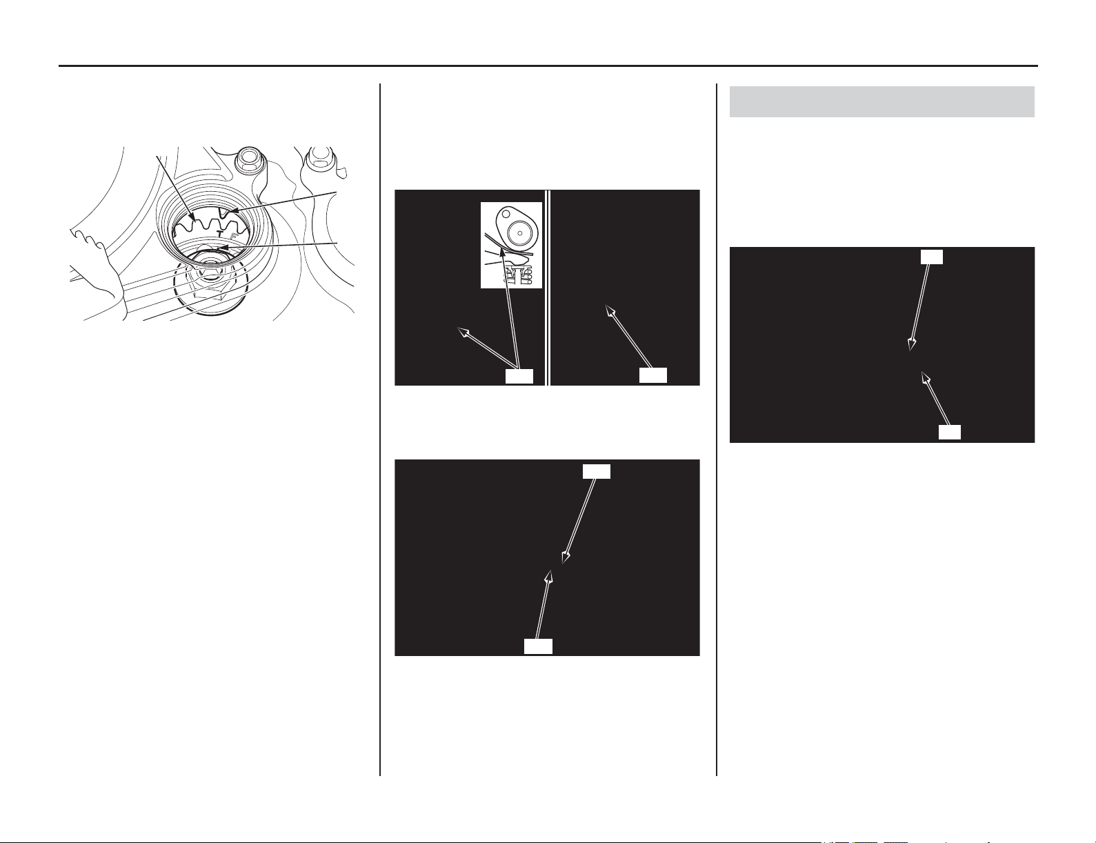
94 Servicing Your Honda
Valve Clearance
13. Check that “T” mark (22) on the primary drive
gear (23) aligns with the index mark (24) on
the right crankcase cover.
14. Rotate the camshaft by rotating the crankshaft
clockwise several times.
15. Measure the intake and exhaust valve
clearances by inserting a feeler gauge (25).
Valve Clearance:
16. Install a new sealing washer (26) and tighten
the cam chain tensioner lifter cover bolt (27).
1. Install the spark plug (page 86).
2. Coat a new O-ring (1) with engine oil and
install it onto the crankshaft hole cap (2).
Apply grease to the crankshaft hole cap
threads. Install and tighten the crankshaft hole
cap to the specified torque:
11 lbf·ft (15 N·m, 1.5 kgf·m)
3. Install the right crankcase over cover
(page 85).
(22) “T” mark
(23) primary drive gear
(24) index mark
(23)
(24)
(22)
IN: 0.004 ± 0.001 in (0.11 ± 0.03 mm)
EX: 0.011 ± 0.001 in (0.28 ± 0.03 mm)
(25) feeler gauge
(26) sealing washer (new)
(27) cam chain tensioner lifter cover bolt
(25)
(25)
Intake side: Exhaust side:
(27)
(26)
Crankshaft Hole Cap Installation
(1) O-ring (new)
(2) crankshaft hole cap
(2)
(1)
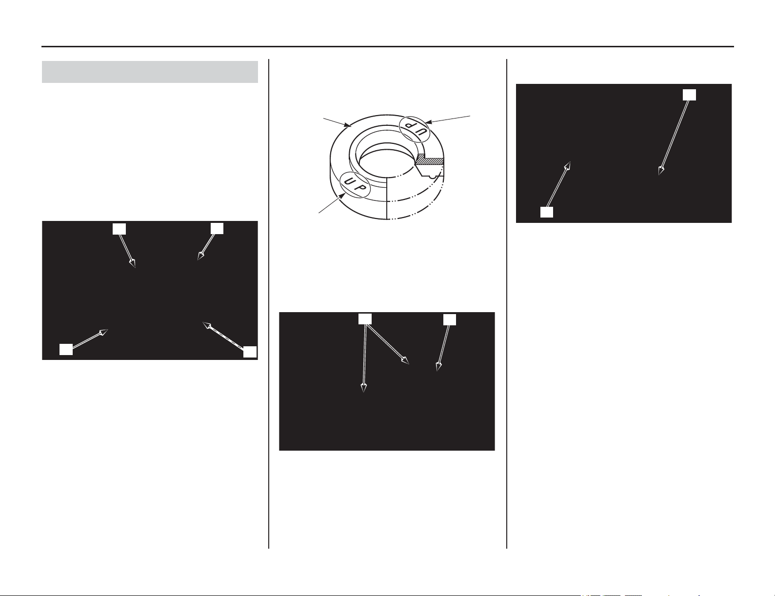
Servicing Your Honda 95
Valve Clearance
1. Check that the spark plug hole packing (1) is in
good condition and replace it if necessary.
Apply engine oil to the spark plug hole packing
and install it to the cylinder head cover (2).
2. Check that the cylinder head cover packing (3)
is in good condition and replace it if necessary.
Clean and apply liquid sealant (TB1207B or
equivalent) to the cylinder head cover groove
(4)
in the shown and install the cylinder head
cover packing into the cylinder head cover
groove.
3. Check that the rubber seals (5) are in good
condition, replace them if necessary.
Install the rubber seals onto the cylinder head
cover with the “UP” marks (6) facing up.
4. Install the cylinder head cover (2) and tighten
the cylinder head cover socket bolts (7) to the
specified torque:
7 lbf·ft (10 N·m, 1.0 kgf·m)
5. Connect the
spark plug cap (8) and breather
tube (9).
6. Install the fuel tank and seat (pages 46, 50).
Cylinder Head Cover Installation
(1) spark plug hole packing
(2) cylinder head cover
(3) cylinder head cover packing
(4) cylinder head cover groove
(3)
(2)
(1)
(4)
(5) rubber seals
(6) “UP” marks
(2) cylinder head cover
(7) cylinder head cover socket bolts
(6)
(6)
(5)
(7)
(2)
(8) spark plug cap
(9) breather tube
(8)
(9)
Piston/Piston Rings/Piston Pin
96 Servicing Your Honda
Piston/Piston Rings/Piston Pin
Refer to Important Safety Precautions on page 33.
1. Clean the area above the engine before
disassembly to prevent dirt falling into the
engine.
2. Drain the radiator coolant after cooling the
motorcycle (page 159).
3. Remove the seat and fuel tank (pages 46, 48).
4. Remove the muffler (page 133).
5. Remove the exhaust pipe (page 134).
6. Remove the subframe (page 52).
7. Remove the spark plug (page 86).
8. Remove the cylinder head cover (page 87).
9. Set the piston at TDC on the compression
stroke (page 88).
10. Remove the camshaft holder, camshaft and
shims (page 89).
11. Disconnect the ignition coil A connector (1)
and B connector (2).
Remove the ignition coil (3) by removing the
ignition coil bolts (4).
12. Remove the right radiator lower mounting bolt
(5) and washer (6).
13. Loosen the insulator band screw (7) and pull
the throttle body (8) out from the insulator (9).
Disconnect the vacuum tube (10) from the
insulator.
Do not hang the throttle body and support it with a
suitable strap.
14. Remove the thermostat case mounting bolts
(11).
Remove the thermostat case assembly (12)
from the cylinder head (13).
Cylinder Head Removal
(1) ignition coil A connector (3) ignition coil
(2) ignition coil B connector (4) ignition coil bolts
(4)
(3)
(2)
(1)
(5) right radiator lower mounting bolt
(6) washer
(7) insulator band screw
(8) throttle body
(9) insulator
(10) vacuum tube
(6) (5)
(7)
(8)
(10)
(9)
(11) bolts
(12) thermostat case
(13) cylinder head
(12)
(13)
(11)
Servicing Your Honda 97
Piston/Piston Rings/Piston Pin
15. Remove the cylinder head hanger bolts (14).
Remove the cylinder head hanger plate bolts
(15), left cylinder head hanger plate (16) and
right cylinder head hanger plate (17).
16. Remove the oil catch tank mounting bolt (18),
oil catch tank (19), collar (20) and stay (21).
17. Remove the cylinder bolt (22).
18. Remove the cylinder head bolts, washers (23)
and cylinder head (24).
Loosen the bolts in a crisscross pattern in two or
three steps.
NOTICE
Do not let the washers and cam chain fall into the
crankcase.
19. Remove the dowel pins (25) and cylinder head
gasket (26).
NOTICE
Do not let the dowel pins and cam chain fall into
the crankcase.
20. Remove the cam chain guide (27) from the
cylinder (28).
(14) cylinder head hanger bolts
(15) cylinder head hanger plate bolts
(16) left cylinder head hanger plate
(17) right cylinder head hanger plate
(15)
(14)
(16)
Left side:
Right side:
(15)
(17)
(14)
(18) bolt (20) collar
(19) oil catch tank (21) oil catch tank stay
(22) cylinder bolt
(23) cylinder head bolts and washers
(24) cylinder head
(21)
(20)
(18)
(19)
(24)
(22)
(23)
(25) dowel pins
(26) cylinder head gasket
(27) cam chain guide
(28) cylinder
(25)
(26)
(27)
(28)
98 Servicing Your Honda
Piston/Piston Rings/Piston Pin
1. Remove the cylinder (1) while holding the
piston (2).
NOTICE
Do not let the cam chain fall into the crankcase.
Do not pry on or strike the cylinder.
2. Remove the dowel pins (3) and cylinder gasket
(4).
NOTICE
Do not let the cam chain fall into the crankcase.
Do not let the dowel pins fall into the crankcase.
1. Place clean shop towels (1) in the crankcase to
keep the piston pin clips, or other parts, from
falling into the crankcase.
2. Remove the piston pin clips (2) using a pair of
needle-nose pliers.
3. Press the piston pin (3) out of the piston (4),
and remove the piston.
Under racing conditions, the piston, rings and
piston pin should be replaced every 8 races or
about every 30.0 hours of running.
NOTICE
Be careful not to damage or shock the piston pin.
Do not clean the piston pin using a commercially
available compound cleaner.
Spread each piston ring (1) and remove by lifting it
up at a point just opposite the gap.
NOTICE
Do not damage the piston ring by spreading the
ends too far.
Cylinder Removal
(1) cylinder (2) piston
(3) dowel pins (4) cylinder gasket
(2)
(1)
(4)
(3)
Piston Removal
(1) shop towels (3) piston pin
(2) piston pin clips (4) piston
(2)
(4) (3)
(1)
(2)
Piston Ring Removal
(1) piston ring
(1)
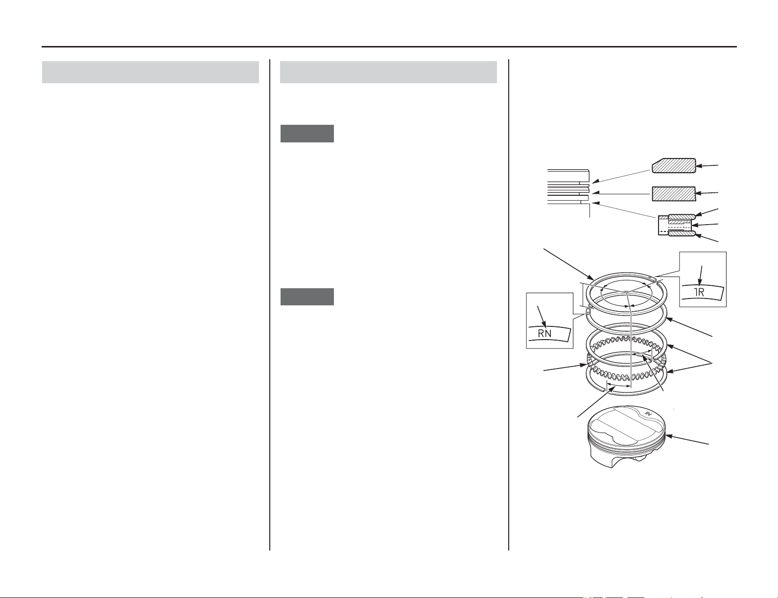
Servicing Your Honda 99
Piston/Piston Rings/Piston Pin
We recommend you consult an official Honda
Service Manual or your dealer for correct Service
Limit measurements.
1. Remove the carbon deposits from the piston
head and piston ring grooves.
NOTICE
Do not damage the piston when removing the
carbon deposit.
2. Apply engine oil to each piston ring whole
surface.
3. Install the spacer (1) first, then install the side
rails (2) to the piston (3).
4. Install the second ring (4) to the piston with
"RN" mark (5) side facing up.
5. Install the top ring (6) to the piston with “1R”
mark (7) side facing up.
NOTICE
Do not damage the piston ring by spreading the
ends too far.
Do not damage the piston during piston ring
installation.
6. After installing the piston rings they should
rotate freely, without sticking. Space the ring
end gaps 120 degrees apart between top ring,
second ring and spacer. Space each ring end
gap 0.8 in (20 mm) or more apart between
upper side rail, spacer and lower side rail as
shown.
Piston/Piston Pin/Piston Ring Inspection Piston Ring Installation
(1) spacer (5) “RN” mark
(2) side rails (6) top ring
(3) piston (7) "1R" mark
(4) second ring
(6)
(4)
(1)
(5)
(1)
(3)
(7)
(4)
(6)
(2)
(2)
0.8 in (20 mm)
or more
0.8 in (20 mm)
or more
(2)
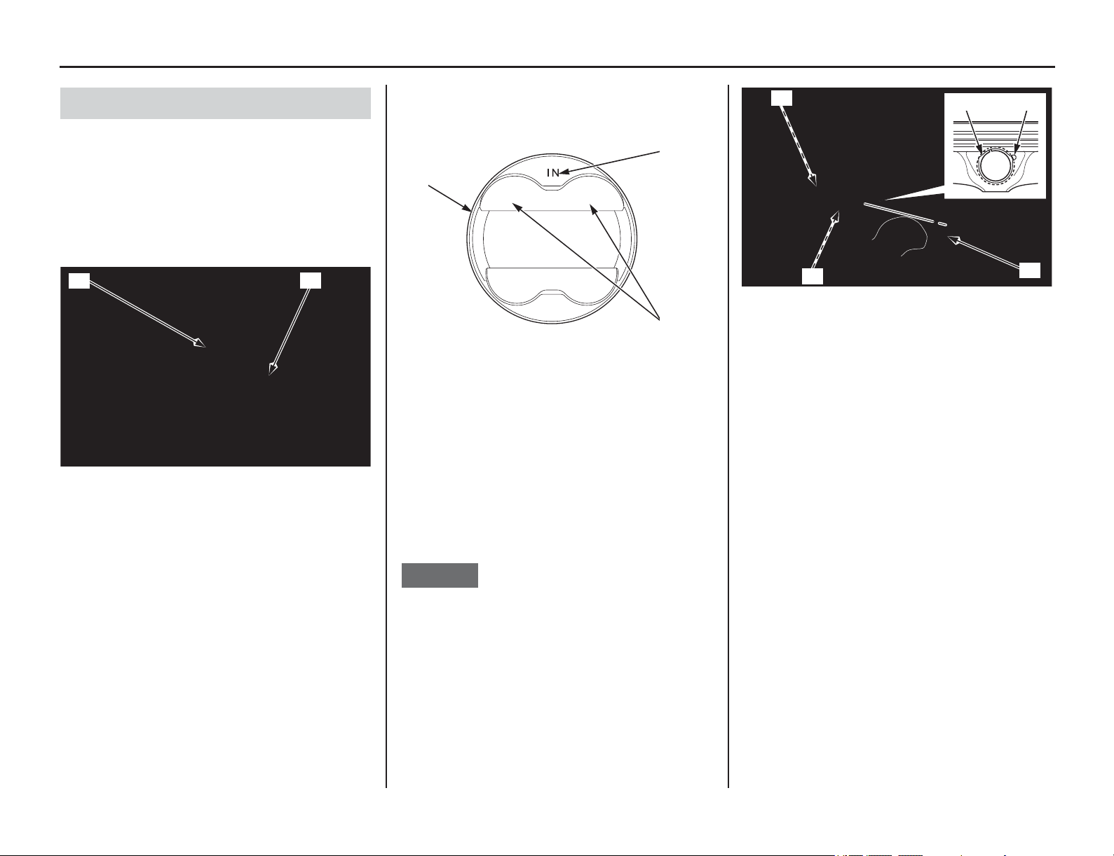
100 Servicing Your Honda
Piston/Piston Rings/Piston Pin
1. Place clean shop towels (1) over the crankcase
opening to keep the piston pin clips from
falling into the crankcase.
2. Apply molybdenum disulfide oil (a mixture of
1/2 engine oil and 1/2 molybdenum disulfide
grease containing more than 3% molybdenum
disulfide additive Moly Paste 77) to the
connecting rod small end (2) inner surface.
3. Install the piston (3) with the “IN” mark (4)
and/or the large valve recesses (5) facing the
intake side of the engine.
Apply molybdenum disulfide oil (a mixture of
1/2 engine oil and 1/2 molybdenum disulfide
grease containing more than 3% molybdenum
disulfide additive Moly Paste 77) to the piston
pin (6) outer surface. Apply engine oil to the
piston outer surface and piston pin hole inner
surface. Install the piston pin and new piston
pin clips (7).
NOTICE
Be careful not to damage or shock the piston pin.
Use new pin clips. Never reuse old clips.
Do not let the clips fall into the crankcase.
Do not align the piston pin clip end gap with the
piston cutout (8).
Piston Installation
(1) shop towels
(2) connecting rod small end
(1)
(2)
(3) piston (5) large valve recesses
(4) “IN” mark
(4)
(5)
(3)
(6) piston pin (8) piston cutout
(7) piston pin clips (new)
(7)
(7)
(7)
(8)
(6)
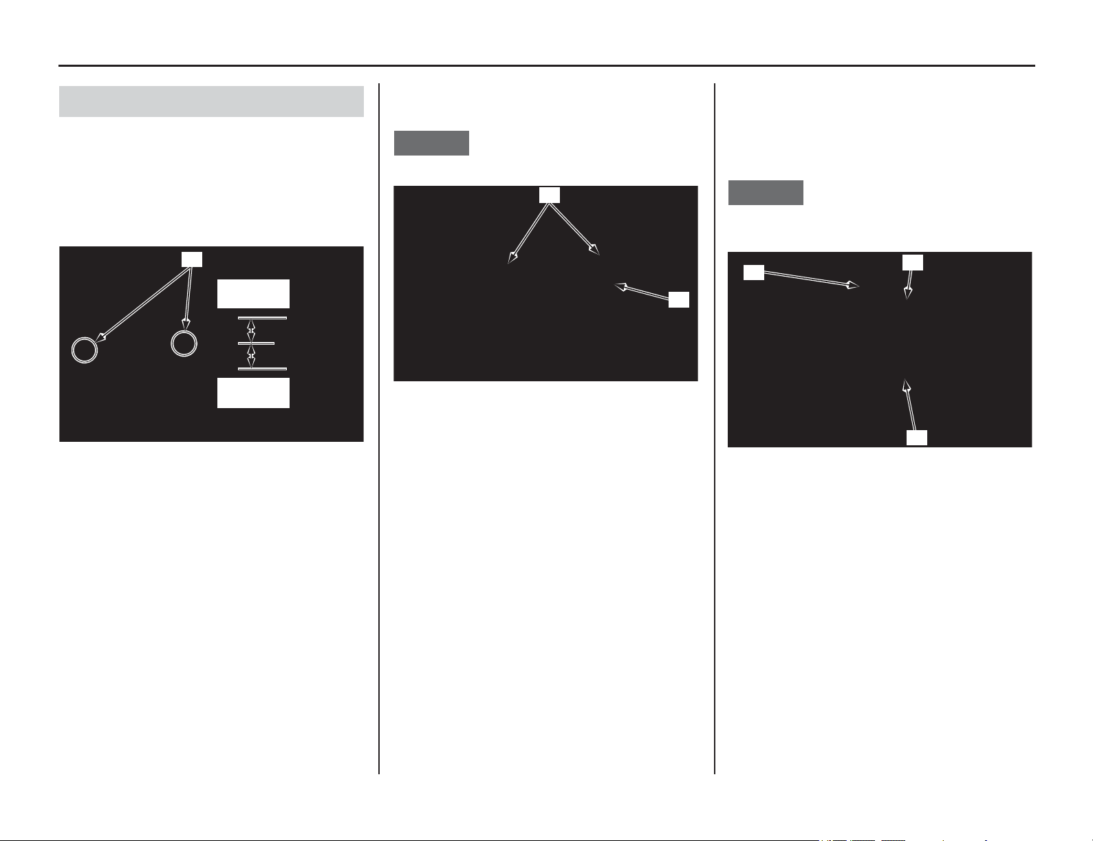
Servicing Your Honda 101
Piston/Piston Rings/Piston Pin
1. Clean the cylinder mating surfaces (1) of the
crankcase, being careful not to let any material
fall into the crankcase.
2. Remove the shop towels.
3. Apply liquid sealant (TB1141G manufactured
by ThreeBond or equivalent) to the cylinder
mating surface of the crankcase side as shown.
4. Install the dowel pins (2) and a new cylinder
gasket (3).
NOTICE
Do not let the dowel pins fall into the crankcase.
5. Apply engine oil to the cylinder bore (4),
piston outer surface and piston rings (5). Route
the cam chain (6) through the cylinder. Install
the cylinder over the piston rings by hand
while compressing the piston rings.
NOTICE
Do not damage the piston rings and cylinder bore.
Do not let the cam chain fall into the crankcase.
Cylinder Installation
(1) cylinder mating surface
0.2 – 0.4 in
(5 – 10 mm)
0.2 – 0.4 in
(5 – 10 mm)
(1)
(2) dowel pins (3) cylinder gasket (new)
(2)
(3)
(4) cylinder bore (6) cam chain
(5) piston rings
(6)
(5)
(4)
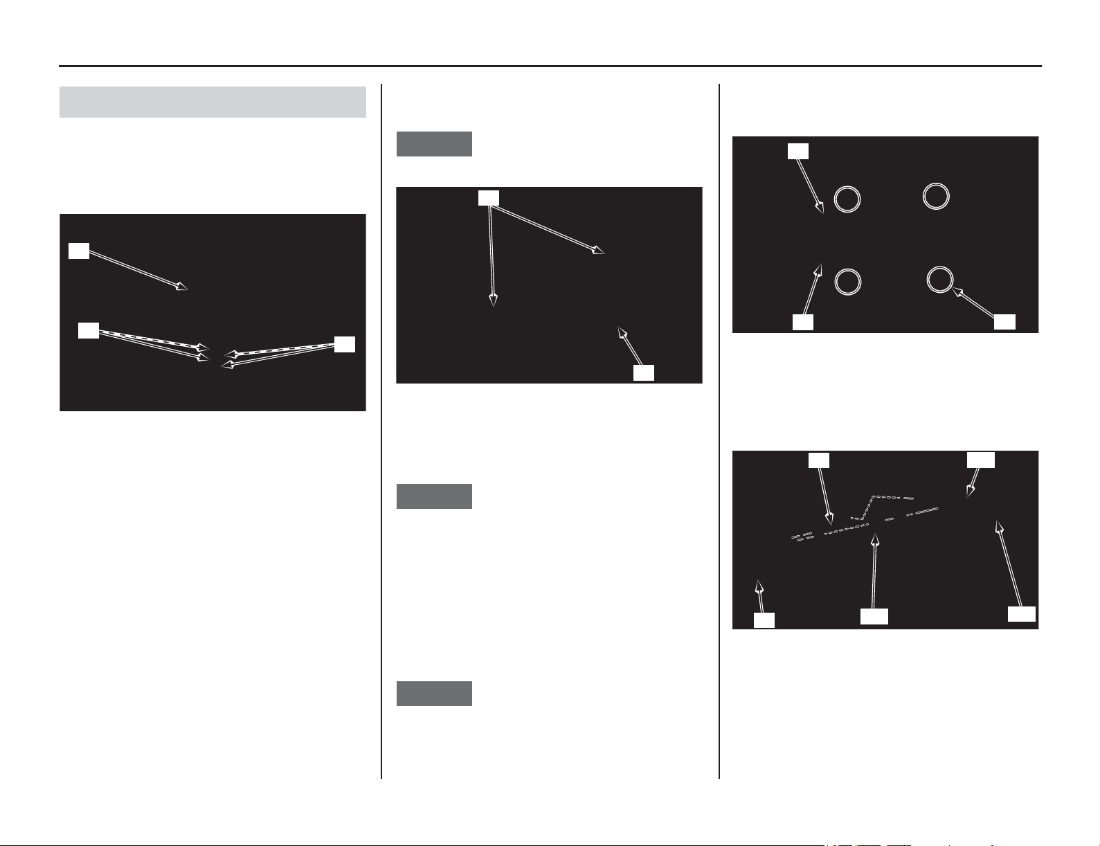
102 Servicing Your Honda
Piston/Piston Rings/Piston Pin
1. Clean any gasket material off cylinder head.
2. Install the cam chain guide (1) and fit the cam
chain guide tabs (2) in the cylinder cutouts (3).
Push the guide until it bottoms in the crankcase
guide groove.
3. Install the dowel pins (4) and a new cylinder
head gasket (5).
NOTICE
Do not let the dowel pins fall into the crankcase.
4. Route the cam chain through the cylinder head
and install the cylinder head (6).
NOTICE
Do not damage mating surfaces when installing
the cylinder head.
5. Apply engine oil to all cylinder head bolt
threads and seating surface.
Install the washers and cylinder head bolts (7)
and tighten them to the specified torque in a
crisscross pattern in two or three steps:
37 lbf·ft (50 N·m, 5.1 kgf·m)
NOTICE
Do not let the washers fall into the crankcase.
6. Install the cylinder bolt (8) and tighten it to the
specified torque:
7 lbf·ft (10 N·m, 1.0 kgf·m)
7. Install the oil catch tank stay (9), collar (10), oil
catch tank (11) to the cylinder head (6), and
then tighten the mounting bolt (12).
Cylinder Head Installation
(1) cam chain guide (3) cylinder cutouts
(2) cam chain guide tabs
(1)
(2)
(3)
(4) dowel pins
(5) cylinder head gasket (new)
(4)
(5)
(6) cylinder head
(7) washers and cylinder head bolts
(8) cylinder bolt
(6) cylinder head (11) oil catch tank
(9) oil catch tank stay (12) mounting bolt
(10) collar
(7)
(8)
(6)
(10)
(12)
(11)
(9)
(6)
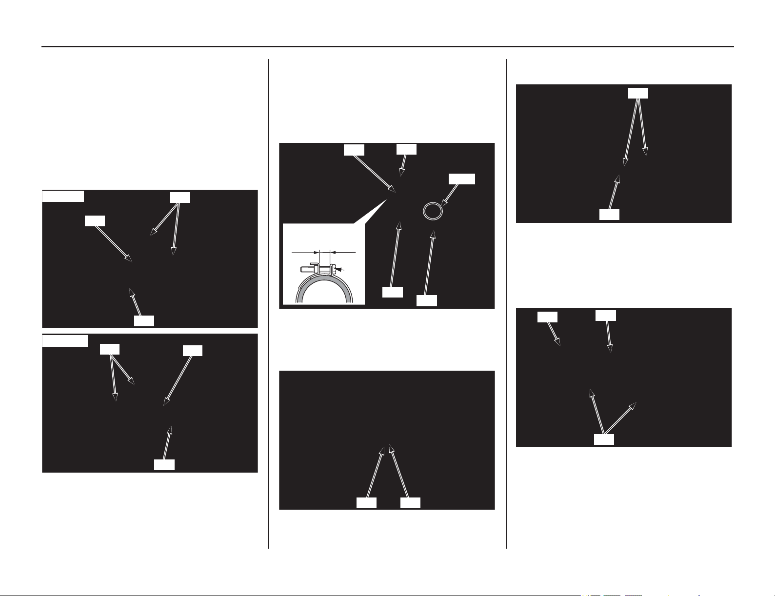
Piston/Piston Rings/Piston Pin
(cont’d)
Servicing Your Honda 103
8. Install the left cylinder head hanger plate (13)
and right cylinder head hanger plate (14), then
loosely install the cylinder head hanger plate
bolts (15) and cylinder head hanger bolts (16).
Tighten the cylinder head hanger bolts and
cylinder head hanger plate bolts to the
specified torque.
cylinder head hanger bolts:
40 lbf·ft (54 N·m, 5.5 kgf·m)
cylinder head hanger plate bolts:
24 lbf·ft (32 N·m, 3.3 kgf·m)
9. Install the throttle body (17) to the insulator
(18)
by aligning the tab of the throttle body
with the
groove of the insulator and tighten the
insulator band screw (19) so the distance
between the band ends is 0.43 ± 0.04 in (11.0 ±
1.0 mm).
10. Connect the vacuum tube (20) to the insulator.
11. Install and tighten the right radiator lower
mounting bolt (21) and washer (22) securely.
12. Install the new O-rings (23) onto the
thermostat case dowel pin (24).
13. Install the thermostat case assembly (25) to the
cylinder head (26), then install and tighten the
mounting bolts (27) to the specified torque:
7 lbf·ft (10 N·m, 1.0 kgf·m)
(13) left cylinder head hanger plate
(14) right cylinder head hanger plate
(15) cylinder head hanger plate bolts
(16) cylinder head hanger bolts
Left side:
(16)
(15)
(13)
Right side:
(15)
(14)
(16)
(17) throttle body (19) insulator band screw
(18) insulator (20) vacuum tube
(21) right radiator lower mounting bolt
(22) washer
(19)
(17)
Align
(20)
0.43 ± 0.04 in
(11.0 ± 1.0 mm)
(19)
(18)
(22) (21)
(23) O-rings (new)
(24) dowel pin
(25) thermostat case assembly
(26) cylinder head
(27) bolts
(24)
(23)
(27)
(25)
(26)
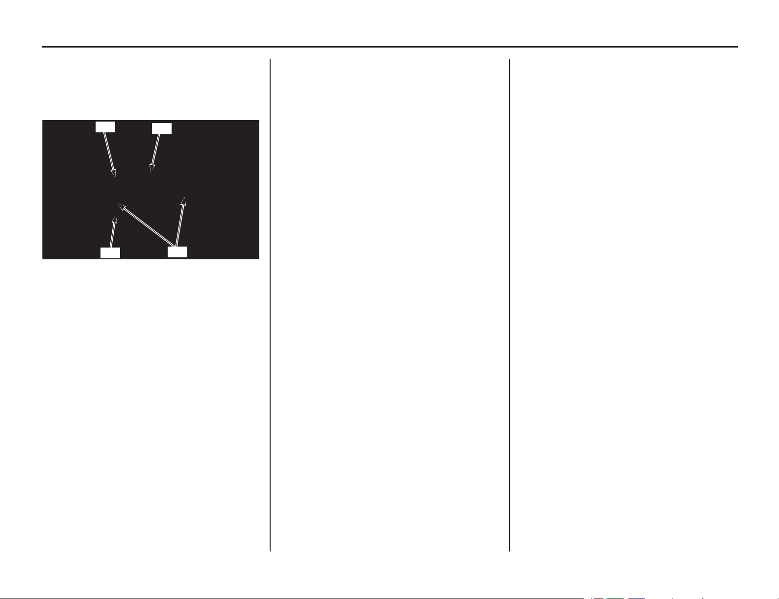
104 Servicing Your Honda
Piston/Piston Rings/Piston Pin
14. Install the ignition coil (28) and tighten the
ignition coil bolts (29) to the specified torque:
7 lbf·ft (10 N·m, 1.0 kgf·m)
Connect the ignition coil A connector (30) and
B connector (31).
15. Install the shims, camshaft and camshaft
holder (page 92).
16. Install the crankshaft hole cap (page 94).
17. Install the cylinder head cover (page 95).
18. Install the spark plug (page 86).
19. Install the exhaust pipe (page 134).
20. Install the subframe (page 55) and muffler
(page 133).
21. Install the fuel tank and seat (pages 46, 50).
22. Fill and bleed the cooling system (page 159).
Check for the following:
– compression leaks
– abnormal engine noise
– secondary air leaks
– exhaust gas leaks
– coolant leaks
– oil leaks
(28) ignition coil
(29) ignition coil bolts
(30) ignition coil A connector
(31) ignition coil B connector
(31)
(29)
(28)
(30)
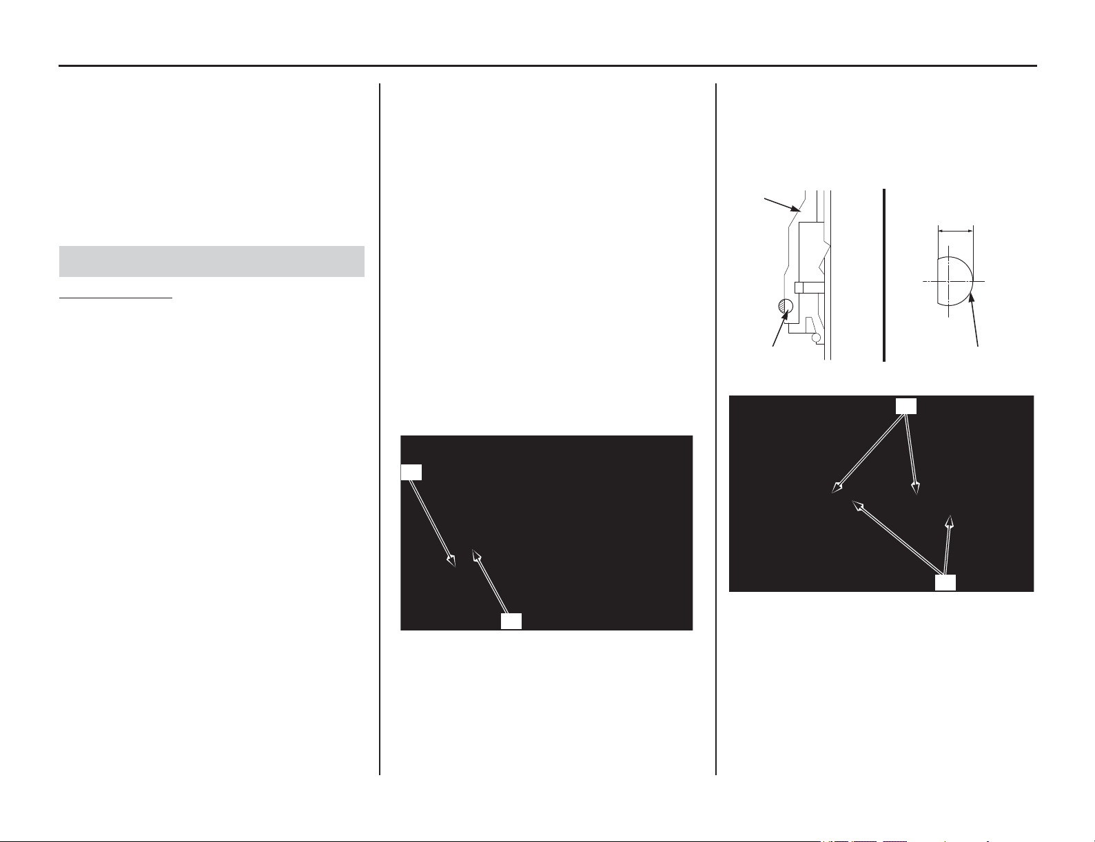
Suspension
(cont’d)
Servicing Your Honda 105
Refer to Important Safety Precautions on page 33.
Loose,
worn, or damaged suspension components
may adversely affect the handling and stability of
your motorcycle. If any suspension components
appear worn or damaged, see your dealer for
further inspection. Your dealer is qualified to
determine whether or not replacement parts or
repairs are needed.
Off-Road use only
• When your motorcycle is new, break it in for
approximately 1 hour to ensure that the
suspension has worked in (page 30).
• After break-in, test run your motorcycle with
the front suspension at the standard setting
before attempting any adjustments.
• For optimum fork performance, we
recommend that you disassemble and clean the
fork after riding your motorcycle for 3 hours.
See page 106 for front suspension removal.
• Replace the fork oil every 8 races or 30.0 hours
of running. See page 111 for oil capacity
adjustment after changing the fork oil.
• Replace the damper oil every 8 races or 30.0
hours of running. See page 115 for damper
fork oil replacement.
• Use Pro Honda HP Fork Oil, SS-19 or an
equivalent which contains special additives to
assure maximum performance of your
motorcycle’s front suspension.
Periodically check and clean all front
suspension parts to assure top performance.
Check the dust seals for dust, dirt, and foreign
materials. Check the oil for any contamination.
•Refer to Suspension Adjustment Guidelines
(page 150). Make all rebound and compression
damping adjustments in one-click increments.
(Adjusting two or more clicks at a time may
cause you to pass over the best adjustment.)
Test ride after each adjustment.
• If you become confused about adjustment
settings, return to the standard position and
start over.
• If the fork is still too stiff/soft after adjusting
compression damping, determine which
portion of the travel is still too stiff/soft. This is
an important step that will help you solve
suspension problems.
1. Make sure that the fork protectors (1) and dust
seals (2) are clean and not packed with mud
and dirt.
2. Check for signs of oil leakage. Damaged or
leaking fork seals should be replaced before
your motorcycle is ridden.
3. Inspect the wear rings (3) for wear or damage.
Replace the wear ring if it is 0.06 in (1.5 mm)
or flush with the outer tube (4). Remove the
fork leg when replacing the wear ring.
Install the wear ring with its end gap (5) facing
rearward.
Front Suspension Inspection
(1) fork protectors (2) dust seals
(1)
(2)
(3) wear rings (4) outer tube
(3) wear rings (5) end gaps
0.06 in (1.5 mm)
(4)
(3) (3)
(5)
(3)
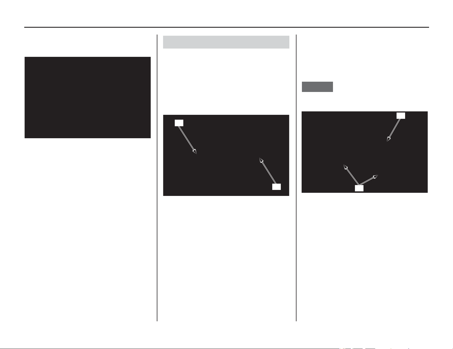
106 Servicing Your Honda
Suspension
4. Make a quick check of fork operation by
locking the front brake and pushing down on
the handlebar several times.
• When removing the wheel, be careful not to
damage the wheel speed sensor and pulser
ring.
• When disassembling the fork, turn the
compression (1) and rebound (2) damping
adjusters counterclockwise to the softest
position to prevent damaging the adjustment
needle (be sure to record the number of turns
from the starting position).
1. Place your motorcycle on an optional
workstand or equivalent support with the front
wheel off the ground.
2. Remove the handlebar lower holder nuts,
washers, mounting rubbers (3) and handlebar
(4).
NOTICE
Keep the master cylinder upright to prevent air
from entering system.
3. Loosen the fork bridge upper pinch bolts (5).
4. Loosen the fork bolts assembly (6), but do not
remove them yet.
Front Suspension Removal
(1) compression damping adjuster
(2) rebound damping adjuster
(1)
(2)
(3) handlebar lower holder nuts, washers and mounting
rubbers
(4) handlebar
(4)
(3)
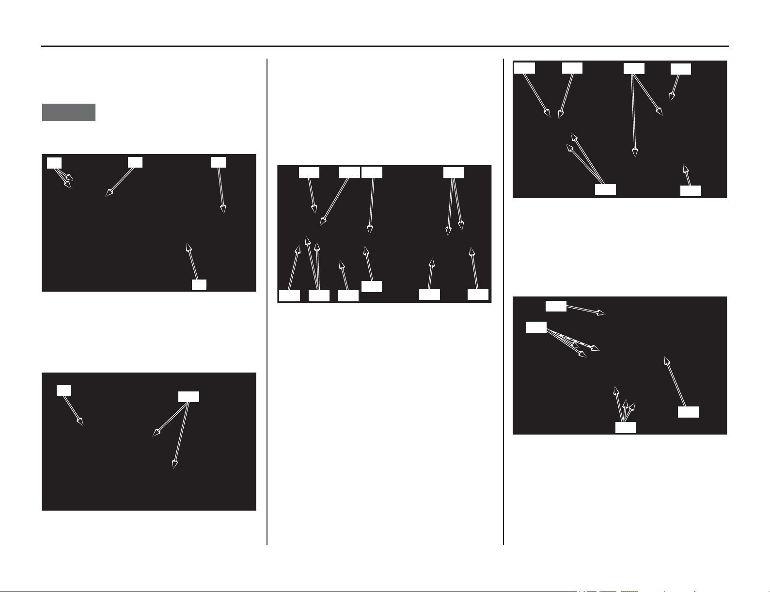
Suspension
(cont’d)
Servicing Your Honda 107
5. Loosen the fork damper assembly (7) using the
lock nut wrench (8), but do not remove them.
• Lock nut wrench 07WMA-KZ30100
NOTICE
Do not use an adjustable wrench to loosen the fork
damper: it may damage them.
6. Remove the disc cover (9) by removing disc
cover socket bolts (10).
7. Remove the speed sensor wire guide plate
screw (11) and guide plate (12).
Remove the speed sensor mounting bolt (13)
and speed sensor (14).
8. Remove the front axle nut (15) and loosen the
axle pinch bolts (16) on both forks.
Pull the front axle shaft (17) out of the wheel
hub and remove the front wheel with collars
(18).
9. Remove the brake hose/speed sensor wire
clamp bolts (19), stay A (20) and stay B (21).
10. Remove the speed sensor wire clip (22) from
the caliper bracket.
Remove the front brake caliper mounting bolts
(23) and brake caliper (24).
• Do not support the brake caliper by the brake
hose.
• Do not operate the brake lever after the front
wheel is removed. To do so will cause
difficulty in fitting the brake disc between
the brake pads.
11. Remove the fork protector socket bolts (25)
and fork protectors (26).
(5) fork bridge upper pinch bolts
(6) fork bolt assembly
(7) fork damper assembly
(8) lock nut wrench
(9) disc cover (10) disc cover socket bolts
(8)
(7)
(5)
(6)
(10)
(9)
(11) screw (15) front axle nut
(12) guide plate (16) axle pinch bolts
(13) bolt (17) front axle shaft
(14) speed sensor (18) collars
(17) (18)
(18)
(11)
(16)
(15)
(12)
(13)
(14)
(16)
(19) brake hose/speed sensor wire clamp bolts
(20) stay A
(21) stay B
(22) wire clip
(23) front brake caliper mounting bolts
(24) brake caliper
(25) fork protector socket bolts
(26) fork protectors
(23)
(24)
(19)
(21) (20)
(22)
(25)
(26)
(25)
(26)
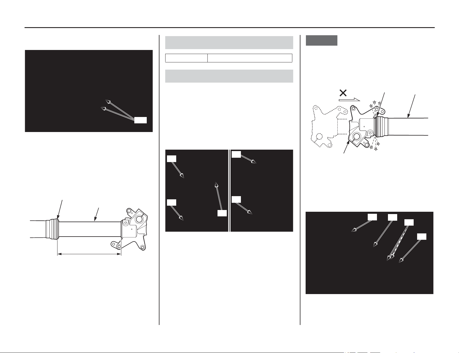
108 Servicing Your Honda
Suspension
12. Loosen the fork bridge lower pinch bolts (27),
then pull the fork legs down and out.
13. Clean the fork assembly, especially the sliding
surface (28) of the slider and fork dust seal
(29).
14. Measure the length (30) between the axle
holder and outer tube and record it before
disassembling the fork.
Refer to Front Suspension Removal on page 106.
1. Clean the fork assembly, especially the sliding
surface of the slider and dust seal.
2. Hold the outer tube (1), then remove the fork
damper assembly (2) from the outer tube using
the lock nut wrench (3). Gently slide the outer
tube down onto the lower end (axle holder) (4).
• Lock nut wrench 07WMA-KZ30100
NOTICE
The outer tube (1) can drop on the axle holder (4)
and damage the fork dust seal (5). To avoid
damage, hold both the outer tube and slider when
removing the fork damper.
3. Drain the fork oil from the outer tube (1) and
oil holes (6) of the fork damper assembly (2).
Remove the O-ring (7) from the fork damper
assembly.
(27) fork bridge lower pinch bolts
(28) sliding surface (30) length
(29) fork dust seal
(27)
(30)
(29)
(28)
Recommended Fork Oil
suggested oil Pro Honda HP Fork Oil, SS-19
Fork Outer Tube Disassembly
(1) outer tube (3) lock nut wrench
(2) fork damper assembly (4) axle holder
(1)
(4)
(2)
(1)
(3)
(1) outer tube (5) fork dust seal
(4) axle holder
(1) outer tube (6) oil holes
(2) fork damper assembly (7) O-ring
(1)
(5)
(4)
(1)
(2)
(7)
(6)
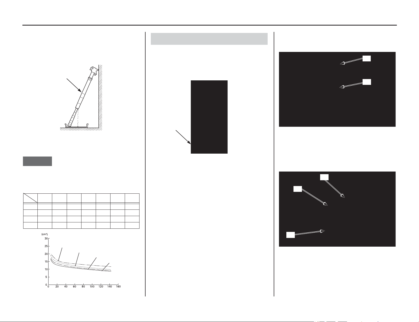
Servicing Your Honda 109
Suspension
4. Drain the fork oil by turning the outer tube (1)
upside down. (About 0.46 US oz (13.7 cm
3
) of
fork oil will be left in the outer tube when it is
left inverted for about 20 minutes at 68°F/
20°C.)
Pour the drained oil into a suitable container and
dispose of it in an approved manner (page 160).
NOTICE
Improper disposal of drained oil is harmful to the
environment.
1. Pour the recommended fork oil into the outer
tube (1).
Be sure the oil capacity is the same in both fork
legs.
Recommended Oil:
Pro Honda HP Fork Oil, SS-19
Recommended Standard Amount:
12.0 US oz (355 cm
3
)
Fill the fork oil which is obtained by docking off
the amount of the remaining oil in the fork from the
recommended standard fork oil capacity.
Refer to Front Suspension Adjustments on
page 144.
2. Apply the recommended fork oil to a new O-ring
(2). Install the O-ring on the fork damper
assembly (3).
3. Pull up the fork outer tube (1) slowly and
temporarily tighten the fork damper assembly
(3) using the lock nut wrench (4).
• Lock nut wrench 07WMA-KZ30100
(1) outer tube
Amount of fork oil left in the fork
(within damper and spring) unit: cm
3
minute
°C/°F
5 1020355585145
30/86 16.5 14.1 12.7 11.8 11 10.1 8.6
20/68 17.4 15 13.7 12.6 11.5 10.5 9.1
10/50 18.9 16.5 14.8 13.7 12.5 11.4 9.8
0/32 20 18.4 15.9 14.5 13.7 13 11.7
(1)
Inverted time
0°C/32°F
10°C/50°F
20°C/68°F
30°C/86°F
Amount of fork oil
(minutes)
Fork Oil Refilling
(1) outer tube
(1)
(2) O-ring (new) (3) fork damper assembly
(1) outer tube (4) lock nut wrench
(3) fork damper assembly
(2)
(3)
(4)
(3)
(1)
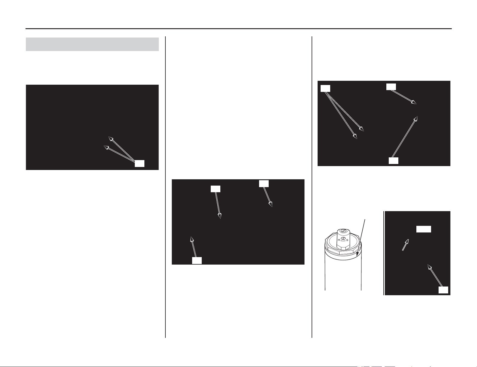
110 Servicing Your Honda
Suspension
1. Insert both fork legs into the fork clamps.
Tighten the fork bridge lower pinch bolts (1) to
the specified torque:
15 lbf·ft (20 N·m, 2.0 kgf·m)
2. Tighten the fork damper assembly (2) to the
specified torque using the lock nut wrench (3):
Actual:
56 lbf·ft (76 N·m, 7.7 kgf·m)
Torque wrench scale reading:
51 lbf·ft (69 N·m, 7.0 kgf·m), using a 20 in
(500 mm) long deflecting beam type torque
wrench.
• Lock nut wrench 07WMA-KZ30100
When using the lock nut wrench, use a 20 in (500
mm)
long deflecting beam type torque wrench.
The
lock nut wrench increases the torque wrench’s
leverage, so the torque wrench reading will be less
than the torque actually applied to the fork damper
assembly.
3. Tighten the fork bolt assembly (4) to the
specified torque:
22 lbf·ft (30 N·m, 3.1 kgf·m)
4. For ease of releasing air pressure after the forks
are installed, loosen the fork bridge lower
pinch bolts (1) and position the outer tubes so
that the fork air pressure release screws (5) are
in front of the compression damping adjuster
(6).
5. Align the groove (7) in the outer tube with the
top surface of the upper fork bridge (8).
Front Suspension Installation
(1) fork bridge lower pinch bolts
(1)
(2) fork damper assembly
(3) lock nut wrench
(4) fork bolt assembly
(4)
(2)
(3)
(1) fork bridge lower pinch bolts
(5) pressure release screw
(6) compression damping adjuster
(7) groove (8) upper fork bridge
(6)
(5)
(1)
Align
(7)
(8)
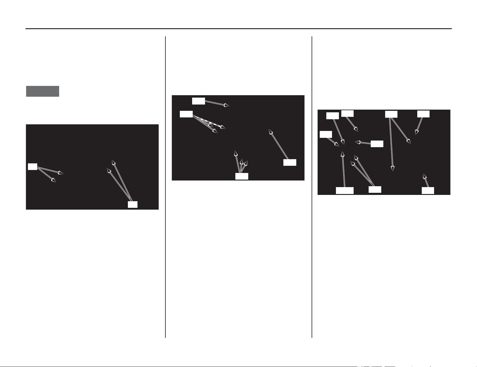
Suspension
(cont’d)
Servicing Your Honda 111
6. Tighten the fork bridge lower pinch bolts (1) to
the specified torque:
15 lbf·ft (20 N·m, 2.0 kgf·m)
7. Tighten the fork bridge upper pinch bolts (9) to
the specified torque:
15 lbf·ft (20 N·m, 2.0 kgf·m)
NOTICE
Over-tightening the pinch bolts can deform the
outer tubes. Deformed outer tubes must be
replaced.
8. Clean the threads of the fork protector socket
bolts (10) and axle holder thoroughly.
Apply locking agent to the bolt threads.
Install the fork protectors (11), fork protector
socket bolts.
Tighten the fork protector socket bolts to the
specified torque:
5.2 lbf·ft (7 N·m, 0.7 kgf·m)
9. Align the brake caliper (12) and brake hose
(13) with the left fork leg, making sure that the
brake hose is not twisted. An improperly
routed brake hose may rupture and cause a loss
of braking efficiency.
10. Align the lower surface of the brake hose
protector (14) with the lower ends of the stay A
(15) and stay B (16), and assemble them.
Install and tighten them to the left fork
protector using the brake hose/speed sensor
wire clamp bolts (17).
11. Clean the threads of the front brake caliper
mounting bolts (18) and brake caliper
thoroughly.
Apply locking agent to the bolt threads.
Install the brake caliper (12) on the slider and
tighten the front brake caliper mounting bolts
to the specified torque:
22 lbf·ft (30 N·m, 3.1 kgf·m)
Install the speed sensor wire clip (19) to the
caliper bracket.
(1) fork bridge lower pinch bolts
(9) fork bridge upper pinch bolts
(1)
(9)
(10) fork protector socket bolts
(11) fork protectors
(10)
(11)
(10)
(11)
(12) brake caliper
(13) brake hose
(14) brake hose protector
(15) stay A
(16) stay B
(17) brake hose/speed sensor wire clamp bolts
(18) front brake caliper mounting bolts
(19) wire clip
(17)
(12)
(18)
(13)
(16)
(15)
Align
(14)
(19)
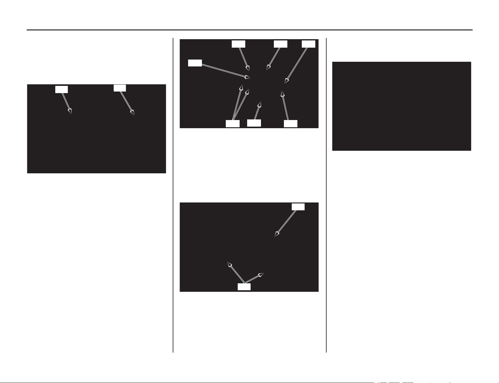
112 Servicing Your Honda
Suspension
12. Clean the surfaces where the axle and axle
clamps contact each other.
Apply grease to each dust seal lips of the front
wheel.
Install the left side collar (20) and right side
collar (21) into the wheel hub.
13. Install the front wheel between the fork legs
while inserting the disc between the pads,
being careful not to damage the pads.
• When installing the wheel, be careful not to
damage the wheel speed sensor and pulser
ring.
14. Insert the front axle shaft through the forks and
wheel hub from the right side. Make sure that
the front axle shaft is seated firmly onto the left
fork leg clamp inner surface. Tighten the front
axle nut (22) to the specified torque:
65 lbf·ft (88 N·m, 9.0 kgf·m)
Tighten the left axle pinch bolts (23) to the
specified torque:
15 lbf·ft (20 N·m, 2.0 kgf·m)
15. Route the speed sensor wire (24) properly and
install the speed sensor (25) to the left fork
bracket. Install and tighten the speed sensor
mounting bolt (26).
Install the speed sensor wire guide plate (27)
and tighten the guide plate screw (28).
16. Install the handlebar (29), mounting rubbers,
washers and handlebar lower holder nuts (30)
and tighten the handlebar holder nuts to the
specified torque:
32 lbf·ft (44 N·m, 4.5 kgf·m)
17. With the front brake applied, pump the fork up
and down several times to seat the axle and
check front brake operation.
(20) left side collar (21) right side collar
(20)
(21)
(22) front axle nut (26) bolt
(23) left axle pinch bolts (27) plate
(24) speed sensor wire (28) screw
(25) speed sensor
(29) handlebar
(30) mounting rubbers, washers and handlebar lower
holder nuts
(27)
(28)
(23)
(22)
(24)(25)
(26)
(30)
(29)
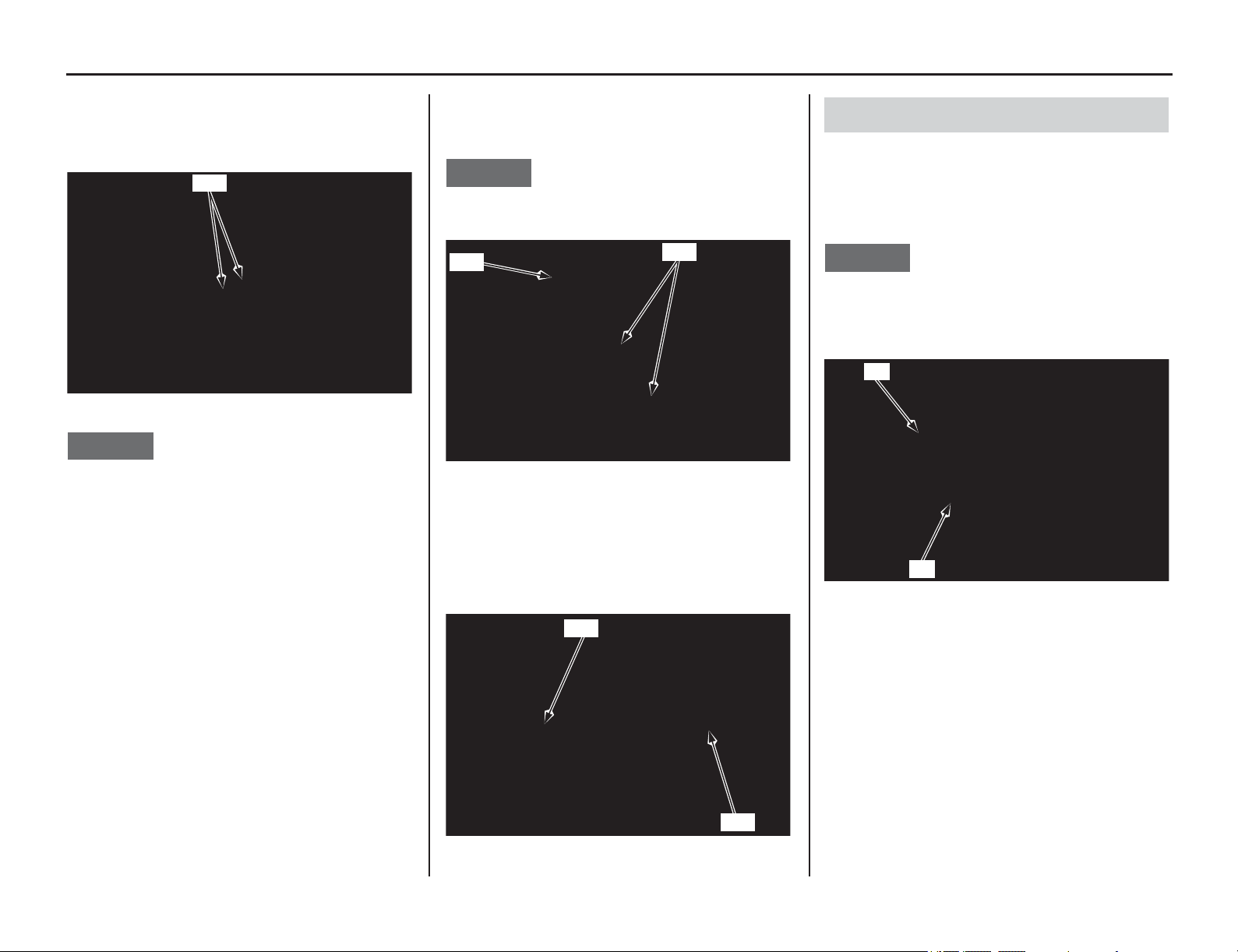
Suspension
(cont’d)
Servicing Your Honda 113
18. While keeping the forks parallel, alternately
tighten the right axle pinch bolts (31) to the
specified torque:
15 lbf·ft (20 N·m, 2.0 kgf·m)
NOTICE
To avoid damage when torquing the axle pinch
bolts, be sure the axle is seated firmly onto the left
fork leg clamp inner surface.
19. Install the disc cover (32) and tighten the disc
cover socket bolts (33) to the specified torque:
10 lbf·ft (13 N·m, 1.3 kgf·m)
NOTICE
Do not ride with the disc cover removed. Doing so
may damage the speed sensor wire.
20. Turn the compression damping (34) and
rebound damping (35) adjuster screws back to
their original settings.
Refer to Front Suspension Damping on page 145.
1. Remove the front suspension (page 106).
2. Disassemble the fork outer tube (page 108).
3. Place the lower end (axle holder) (1) of the
slider in a vise with a piece of wood or soft
jaws to avoid damage.
NOTICE
Over-tightening the vise can damage the axle
holder.
4. Loosen the fork center bolt (2).
5. Pull up the fork outer tube slowly and
temporarily tighten the fork damper assembly
(page 109). Push the outer tube until the fork
center bolt lock nut (3) is fully exposed and
install the piston base (4) or mechanic’s
stopper tool between the axle holder (1) and
fork center bolt lock nut.
• Piston base 07958-2500001
(31) right axle pinch bolts
(31)
(32) disc cover (33) disc cover socket bolts
(34) compression damping adjuster
(35) rebound damping adjuster
(32)
(33)
(34)
(35)
Fork Damper Disassembly
(1) axle holder (2) fork center bolt
(1)
(2)

114 Servicing Your Honda
Suspension
6. Make the mechanic’s stopper tool out of a thin
piece of steel (0.08 in (2.0 mm) thick) as shown
if you do not have a special tool.
7. Hold the fork center bolt lock nut (3) and
remove the fork center bolt (2) from the fork
damper.
NOTICE
Do not remove the lock nut from the fork damper
piston rod. If the lock nut is removed, the piston
rod will fall in the fork damper and you may not
reassemble the fork damper.
8. Remove the push rod (5) from the fork damper.
9. Remove the piston base (4) or mechanic’s
stopper tool between the axle holder (1) and
fork center bolt lock nut (3) while pushing the
fork outer tube.
NOTICE
Be careful not to damage the lock nut and fork
center bolt hole.
10. Remove the fork damper assembly (6) from
the fork assembly (7).
Remove the fork from the vise.
Remove the fork spring (8), spring seat collar
(9) and back-up ring/seat stopper (10) from the
fork assembly.
NOTICE
Do not attempt to separate the fork assembly and
drop the axle holder out from the outer tube, which
can damage the guide bushings (11).
To avoid damage, hold both the outer tube and
slider.
(1) axle holder (3) fork center bolt lock nut
(2) fork center bolt (4) piston base
2.2 in (55 mm)
1.0 in
(25 mm)
0.30 in
(7.5 mm)
0.6 in
(15 mm)
1.5 in (39 mm)
(1)
(3)
(4)
(2)
(1) axle holder (4) piston base
(3) fork center bolt lock nut (5) push rod
(1)
(4)
(5)
(3)
(11) guide bushing
(6) fork damper assembly
(7) fork assembly
(8) fork spring
(9) spring seat collar
(10) back-up ring/seat stopper
(11)
(9)
(6)
(7)
(8)
(10)
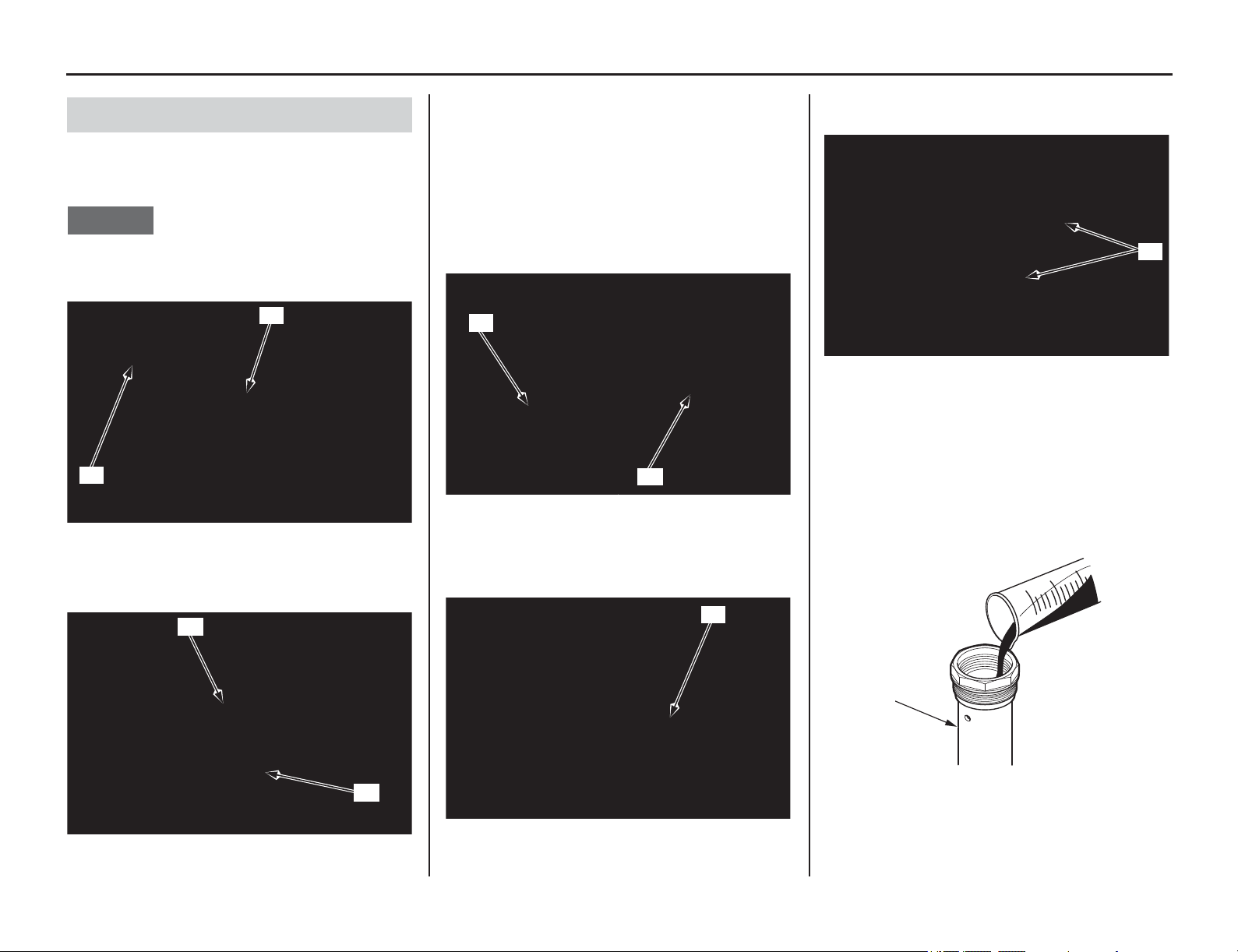
Suspension
(cont’d)
Servicing Your Honda 115
1. Check the fork center bolt lock nut (1) is
installed on the fork damper piston rod (2)
properly.
NOTICE
If the lock nut was removed, the piston rod will fall
into the fork damper and you will not be able to
reassemble the fork damper.
2. Loosen the fork bolt assembly (3) while
holding the fork damper assembly (4).
3. Remove the fork bolt assembly (3) from the
fork damper threads and then pop it out by
pumping the fork damper piston rod (2)
slowly.
4. Remove the fork bolt assembly (3).
Be careful not to damage the fork bolt bushings.
Do not disassemble the fork bolt assembly.
Replace the fork bolt as an assembly if it is
damaged.
5. Empty the fork oil from the fork damper
assembly (4) by pumping the damper rod
several times.
6. Clean the fork bolt and fork damper assembly
threads (5).
7. Extend the fork damper piston rod to
maximum length.
Pour the recommended fork oil into the fork
damper assembly (4).
Recommended Oil:
Pro Honda HP Fork Oil, SS-19
Recommended Amount:
8.4 US oz (248 cm
3
)
Damper Oil Change
(1) fork center bolt lock nut
(2) fork damper piston rod
(3) fork bolt assembly (4) fork damper assembly
(1)
(2)
(3)
(4)
(2) fork damper piston rod (3) fork bolt assembly
(4) fork damper assembly
(2)
(3)
(4)
(5) fork bolt and fork damper assembly threads
(4) fork damper assembly
(5)
(4)
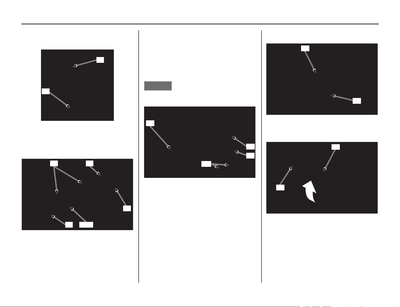
116 Servicing Your Honda
Suspension
8. Pump the fork damper piston rod (2) slowly
several times to bleed the air from the fork
damper assembly (4).
9. Apply fork oil to the fork bolt bushings (6),
new O-rings (7) and new piston ring (8) on the
fork bolt assembly (3).
10. Cover the oil holes (10) of the fork damper
assembly with a shop towel and compress the
piston rod (2) all the way.
Pull the piston rod out 0.8 in (20 mm) and
install the fork bolt assembly (3) into the fork
damper assembly (4).
Push the fork bolt assembly in slowly while
pulling the piston rod out.
NOTICE
Be careful not to damage the fork bolt piston ring.
11. Temporarily tighten the fork bolt assembly (3)
to the fork damper assembly (4).
12. Completely screw in the fork center bolt lock
nut (1) to the fork damper piston rod (2).
13. Check the fork damper piston rod sliding
surface and threads for damage.
(2) fork damper piston rod
(4) fork damper assembly
(3) fork bolt assembly (7) O-rings (new)
(6) fork bolt bushings (8) piston ring (new)
(4)
(2)
(7)
(7) (8)(7)
(3)(6)
(2) fork damper piston rod (4) fork damper assembly
(3) fork bolt assembly (10) oil holes
(3)
(4)
(2)
(10)
(3) fork bolt assembly (4) fork damper assembly
(1) fork center bolt lock nut
(2) fork damper piston rod
(4)
(3)
(1)
(2)
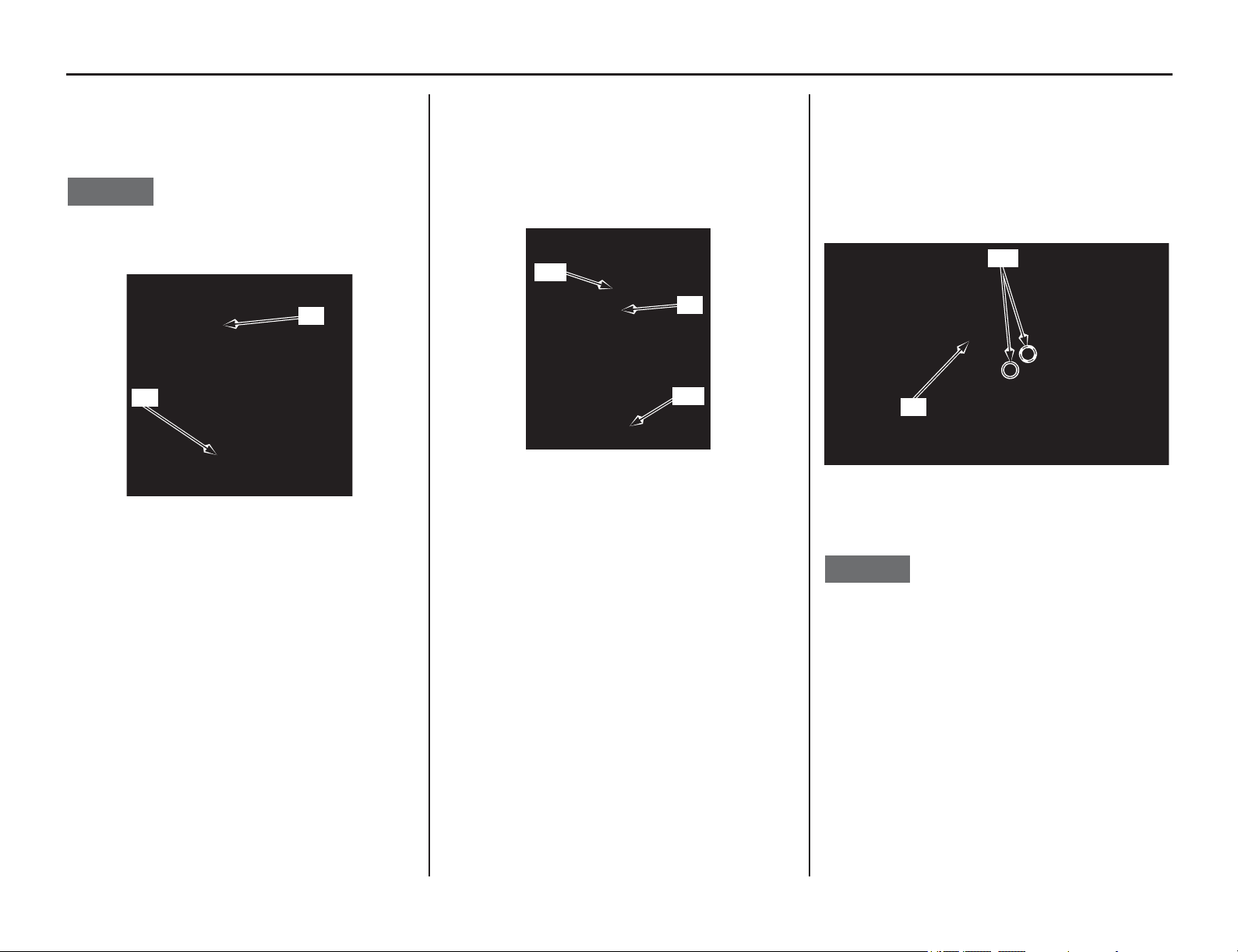
Suspension
(cont’d)
Servicing Your Honda 117
14. Hold the fork damper assembly (4) in an
upright position and pump the fork damper
piston rod (2) 3.9 in (100 mm) slowly, several
times.
NOTICE
Be careful not to bend or damage the fork damper
piston rod when the piston rod is stroked.
15. Cover the fork damper piston rod end with
shop towel (11) to prevent fork damage.
Cover the oil holes with shop towel to prevent
blow out of fork oil.
Blow the extra oil off from the fork damper
assembly (4) by pumping the fork damper
piston rod to full stroke.
16. Drain the extra oil from the oil holes (10) of the
fork damper assembly (4).
By doing above procedure, about 0.2 US oz (5
cm
3
) of fork oil will be drained from the fork
damper through the oil hole and cause 8.2 US oz
(243 cm
3
) of fork oil to be left in the fork damper
assembly.
Pour the drained oil into a suitable container and
dispose of it in an approved manner (page 160).
NOTICE
Improper disposal of drained fluids is harmful to
the environment.
(2) fork damper piston rod (4) fork damper assembly
(4)
(2)
(4) fork damper assembly (11) shop towel
(11)
(11)
(4)
(4) fork damper assembly (10) oil holes
(4)
(10)
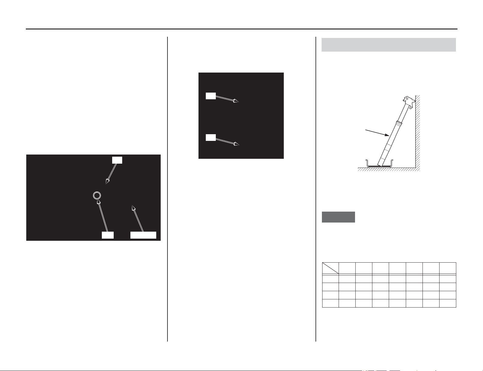
118 Servicing Your Honda
Suspension
17. Blow out any oil from the oil hole (10) of the
fork damper assembly (4) using compressed
air.
Wipe off the oil completely from the fork
damper.
18. If your cannot use compressed air, remove the
fork air pressure release screws (12) from the
fork bolt assembly.
Hold the fork damper upside down for 20
minutes and drain the fork oil.
Apply recommended fork oil to a new O-ring
(13), and then install a new O-rings on the air
pressure release screws (12).
Tighten the air pressure release screws to the
specified torque:
1.0 lbf·ft (1.3 N·m, 0.1 kgf·m)
19. Fully stroke the piston rod (2) by pushing
down the fork damper assembly (4).
Check the piston rod for smooth operation.
If the piston rod operation is not smooth, check
the piston rod for bends or damage.
1. Drain the fork oil from the fork assembly (1)
by placing it upside down.
(About (0.2 US oz (5.4 cm
3
) of fork oil will be
left in the fork assembly when it is left inverted
for about 20 minutes at 20 °C/68 °F)
To properly dispose of drained fluids, refer to You
& the Environment on page 160.
NOTICE
Improper disposal of drained fluids is harmful to
the environment.
(4) fork damper assembly
(10) oil hole
(12) air pressure release screws
(13) O-rings (new)
(4)
(10) (12) (13)
(2) fork damper piston rod
(4) fork damper assembly
(4)
(2)
Fork Damper Installation
(1) fork assembly
Amount of fork oil left in the fork
(without damper and spring) unit: cm
3
minute
°C/°F
5 1020355585145
30/86 6.5 5.7 5.2 4.5 4.1 3.7 3.3
20/68 6.7 6.2 5.4 4.7 4.4 3.8 3.5
10/50 7.3 6.4 5.6 5 4.6 4.2 3.8
0/32 8.6 8.2 7.9 7.6 7.3 6.8 6
(1)
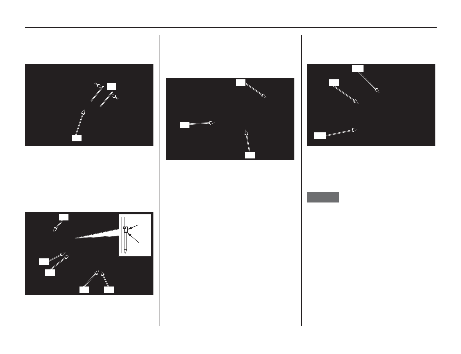
Suspension
(cont’d)
Servicing Your Honda 119
2. Tighten the fork center bolt lock nut (2) fully
and measure the thread length (A) as shown.
Standard: 0.35 – 0.43 in (9 – 11 mm)
Wipe the oil completely off the fork damper.
3. Apply recommended fork oil to the slider
bushing (3).
Install the seat stopper (4), back-up ring (5)
and spring seat collar (6) to the fork damper
(7).
Make sure the black side of the back-up ring is
seated on the seat stopper side.
4. Blow out the oil completely off the fork spring
(8).
Put the fork spring on the fork damper
assembly (9).
Install the spring/fork damper assembly into
the fork assembly (1).
5. Temporarily tighten the fork damper assembly
(9)
to the outer tube (10) using the lock nut
wrench (11).
• L
ock nut wrench 07WMA-KZ30100
6. Place the lower end (axle holder) (12) of the
slider in a vise with a piece of wood or soft
jaws to avoid to damage.
NOTICE
Over-tightening the vise can damage the axle
holder.
7. Push the outer tube until the fork center bolt
lock nut (2) is fully exposed and install the
piston base (13) or mechanic’s stopper tool
between the axle holder (12) and fork center
bolt lock nut.
Measure the thread length again.
Standard: 0.35 – 0.43 in (9 – 11 mm)
• Piston base 07958-2500001
(2) fork center bolt lock nut (A) thread length
(3) slider bushing (6) spring seat collar
(4) seat stopper (7) fork damper
(5) back-up ring
(A)
(2)
(4)
(5)
(7)
(4)
(5)
(6) (3)
(1) fork assembly (9) fork damper assembly
(8) fork spring
(9)
(8)
(1)
(9) fork damper assembly (11) lock nut wrench
(10) outer tube
(9)
(10)
(11)
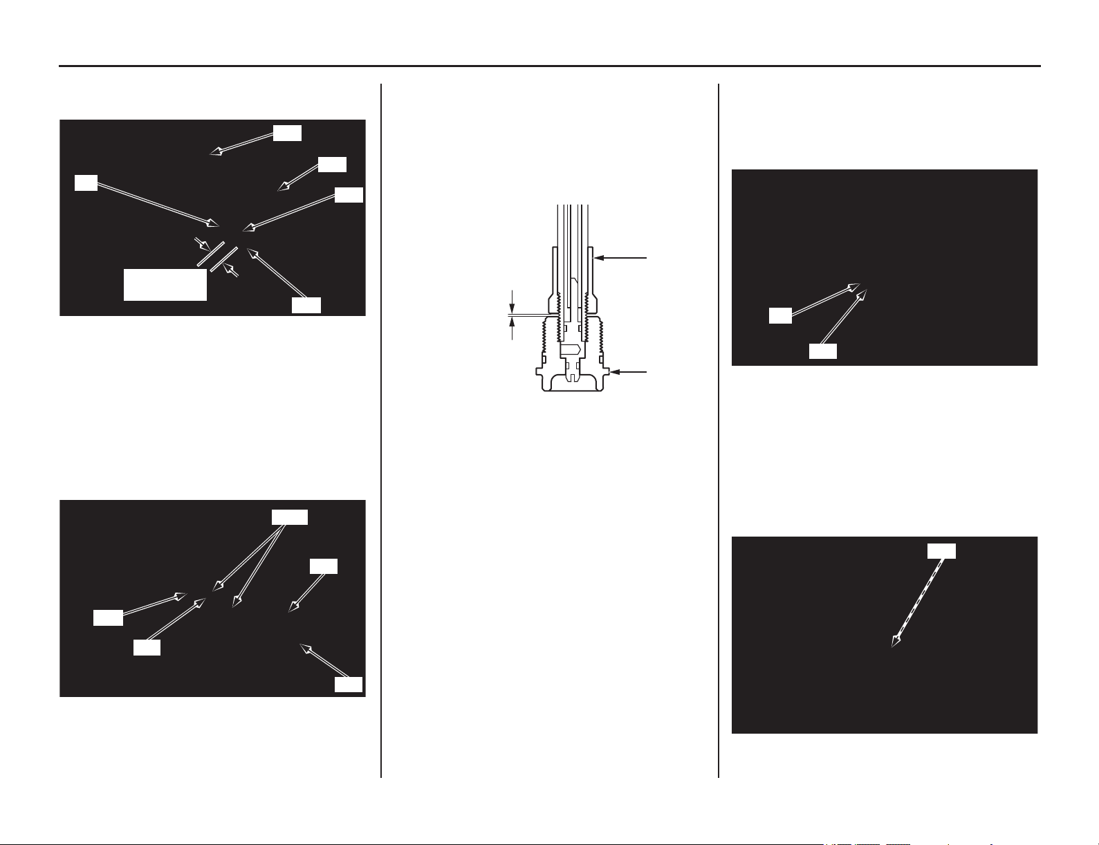
120 Servicing Your Honda
Suspension
8. Install the push rod (14) into the piston rod (15)
until it stops.
9. Apply fork oil to new O-ring (16) and install it
to the fork center bolt (17).
Install the fork center bolt to the fork damper
piston rod (15) by aligning the each flat-side of
the fork center bolt adjusting piston rod and
push rod (14).
Tighten the fork center bolt fully by hand.
10. Measure the clearance between the fork center
bolt lock nut (2) and fork center bolt (17).
Standard: 0.06 – 0.08 in (1.5 – 2.0 mm)
If the clearance is out of specification, check the
fork center bolt lock nut and fork center bolt
installation.
11. Tighten the fork center bolt lock nut (2) to the
fork center bolt (17) closely by hand. Tighten
the fork center bolt lock nut to the specified
torque:
21 lbf·ft (28 N·m, 2.9 kgf·m)
12. Apply locking agent to the fork center bolt
threads.
Remove the piston base or mechanic’s stopper
tool while pushing the fork damper.
Install the fork center bolt (17) to the axle
holder and tighten it to the specified torque:
51 lbf·ft (69 N·m, 7.0 kgf·m)
(2) fork center bolt lock nut (14) push rod
(12) axle holder (15) piston rod
(13) piston base
(14) push rod (16) O-ring (new)
(15) piston rod (17) fork center bolt
(12)
(2)
(13)
(15)
(14)
0.35 – 0.43 in
(9 – 11 mm)
(15)
(14)
(17)
(16)
Align
(2) fork center bolt lock nut (17) fork center bolt
(2)
(17)
0.06 – 0.08 in
(1.5 – 2.0 mm)
(2) fork center bolt lock nut
(17) fork center bolt
(17) fork center bolt
(2)
(17)
(17)
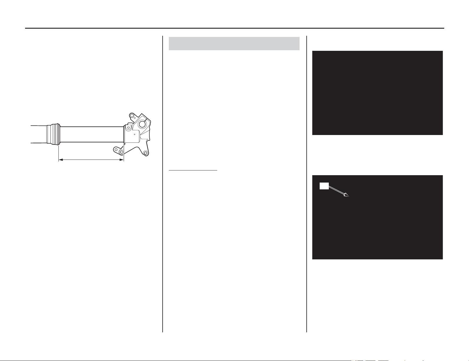
Servicing Your Honda 121
Suspension
13. Remove the fork from the vice.
14. Measure the length between the axle holder
and outer tube.
Standard: 12.3 ± 0.1 in (312 ± 2 mm)
15. Compare the length (18) at assembly and at
disassembly. They should be the same length.
If the length at assembly is longer than at
disassembly, check the fork center bolt and fork
center bolt lock nut installation.
16. Refilling the fork oil (page 109).
17. Install the front suspension (page 110).
The swingarm is controlled by one hydraulic shock
absorber with an aluminum reservoir for oil and
nitrogen gas pressure. The gas pressure in the
reservoir is contained within a rubber bladder.
The rear suspension’s spring pre-load (Off-Road
use only) and compression damping and rebound
damping adjustments should be adjusted for the
rider’s weight and track conditions (pages 148,
152).
Do not attempt to disassemble, service, or dispose
of the damper; see your dealer.
The instructions found in this owner’s manual are
limited to adjustments of the shock assembly only.
Off-Road use only
• When your motorcycle is new, break it in for
approximately 1 hour with the standard
suspension settings before attempting to adjust
the rear suspension.
•Refer to Suspension Adjustment Guidelines
(page 152) for making all rebound and
compression damping adjustments in one click
or 1/12 turn increments. (Adjusting two or
more clicks or turns at a time may cause you to
pass over the best adjustment.)
Test ride after each adjustment.
• If the rear suspension is too stiff/soft, adjust it
by turning all the compression and rebound
adjusters according to the procedures
described in page 152. After adjusting the
adjusters simultaneously, suspension may be
fine-tuned by turning one of the compression
and rebound damping adjusters in one click or
in 1/12 turn increments.
• If you have a problem finding an acceptable
adjustment, return to the standard position and
begin again.
1. Bounce the rear of the motorcycle up and down
and check for smooth suspension action.
2. Remove the muffler (page 133), and subframe
(page 52).
3. Check for a broken or collapsed spring.
4. Check the rear shock absorber (1) for a bent
rod or oil leaks.
5. Push the rear wheel sideways to check for
worn or loose swingarm bearings. There
should be no movement. If there is, have the
bearings replaced by your dealer.
(18) length
(18)
Rear Suspension Inspection
(1) rear shock absorber
(1)
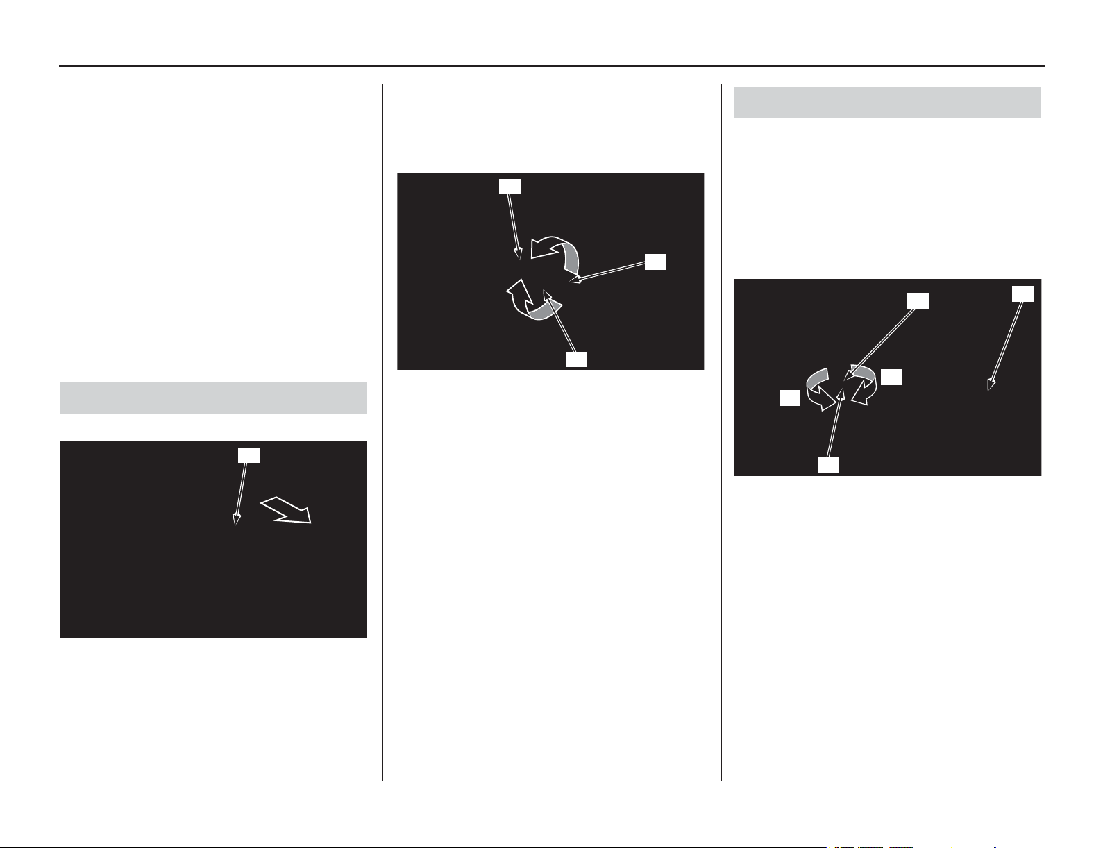
Brakes
122 Servicing Your Honda
Refer to Important Safety Precautions on page 33.
B
oth the front and rear brakes are the hydraulic
disc type. As the brake pads wear, the brake fluid
level will drop. A leak in the system will also cause
the level to drop.
Frequently inspect the system to ensure there are
no fluid leaks. Periodically inspect the brake fluid
level and the brake pads for wear.
If the braking response of the front brake lever or
rear pedal feels unusual, check the brake pads. If
the brake pads are not worn beyond the
recommended limit (page 125), there is probably
air in the brake system.
Refer to an official Honda Service Manual or see
your dealer to have the air bled from the system.
1. Slide the front brake lever cover (1).
2. Loosen the lock nut (2).
3. To position the front brake lever farther away
from the handgrip, turn the adjuster (3)
clockwise.
To position the front brake lever closer to the
handgrip, turn the adjuster counterclockwise.
4. While holding the adjuster, tighten the lock nut
to the specified torque:
3.6 lbf·ft (4.9 N·m, 0.5 kgf·m)
5. Apply silicone grease to the contacting areas of
the adjuster and knocker arm (4).
6. Install the front brake lever cover in reverse
order.
The rear brake pedal height should be
approximately level with the right footpeg.
1. Loosen the lock nut (1) and turn the push rod
(2) in direction (+) to raise the rear brake pedal
(3)
or in direction (–) to lower it.
2. Tighten the push rod lock nut to the specified
torque at the desired pedal height.
4.4 lbf·ft (5.9 N·m, 0.6 kgf·m)
Front Brake Lever Adjustment
(1) brake lever cover
(1)
(2) lock nut (4) knocker arm
(3) adjuster
(3)
(2)
(4)
Rear Brake Pedal Height
(1) lock nut (+) raise the pedal height
(2) push rod (–) lower the pedal height
(3) rear brake pedal
(1)
(3)
(2)
(–)
(+)
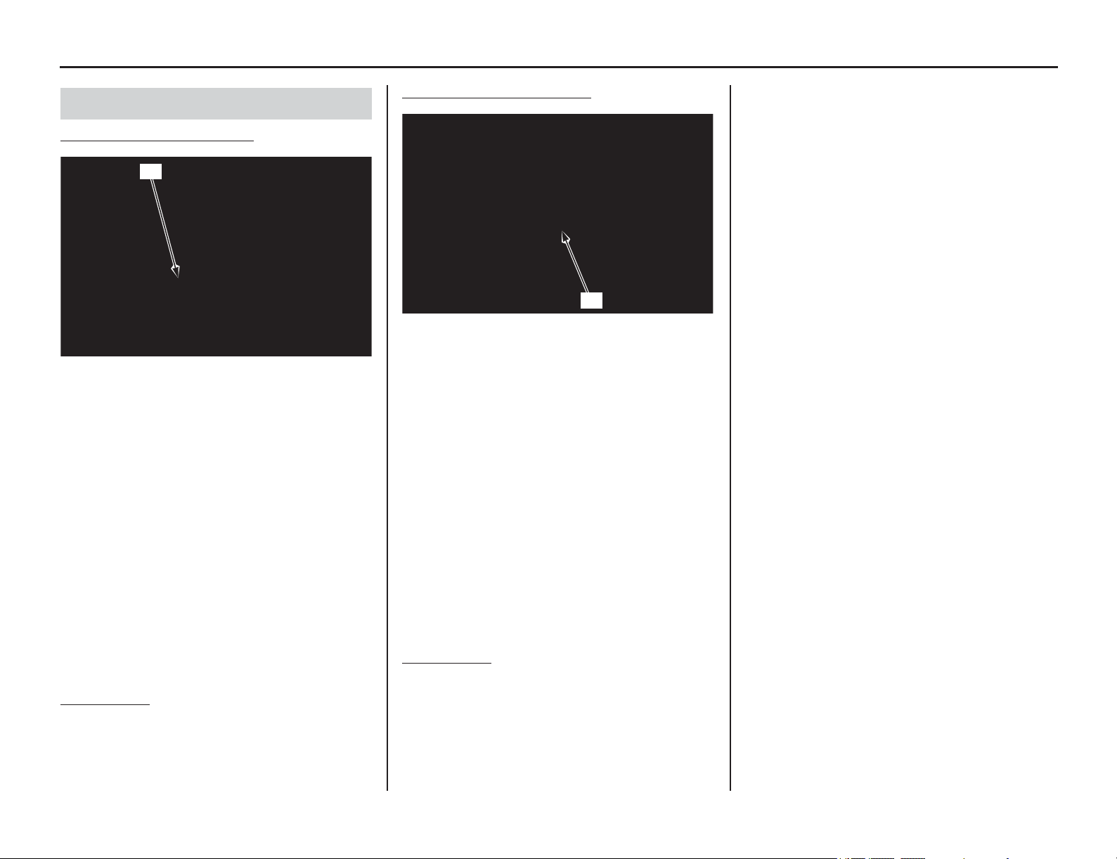
Servicing Your Honda 123
Brakes
Front Brake Fluid Level Check
With the motorcycle in an upright position, check
the fluid level.
It should be above the LWR mark (1). If the level
is at or below the LWR mark, check the brake pads
for wear (page 125).
Worn brake pads should be replaced. If the pads
are not worn, have your brake system inspected for
leaks.
If the pulling distance for the front brake lever
feels excessive, there is probably air in the brake
system and it must be bled. Refer to an official
Honda Service Manual or see your dealer for brake
bleeding.
Honda recommends using Honda DOT 4 Brake
Fluid from a sealed container, or an equivalent.
Other Checks:
Make sure there are no fluid leaks. Check for
deterioration or cracks in the hoses and fittings.
Rear Brake Fluid Level Check
With the motorcycle in an upright position, check
the fluid level.
It should be above the LOWER mark (1). If the
level is at or below the LOWER mark, check the
brake pads for wear (page 125).
Worn brake pads should be replaced. If the pads
are not worn, have your brake system inspected for
leaks.
If the travel for the rear brake pedal feels
excessive, there is probably air in the brake system
and it must be bled. Refer to an official Honda
Service Manual or see your dealer for brake
bleeding.
Honda recommends using Honda DOT 4 Brake
Fluid from a sealed container, or an equivalent.
Other Checks:
Make sure there are no fluid leaks. Check for
deterioration or cracks in the hoses and fittings.
Fluid Level Inspection
(1) LWR mark
(1)
(1) LOWER mark
(1)
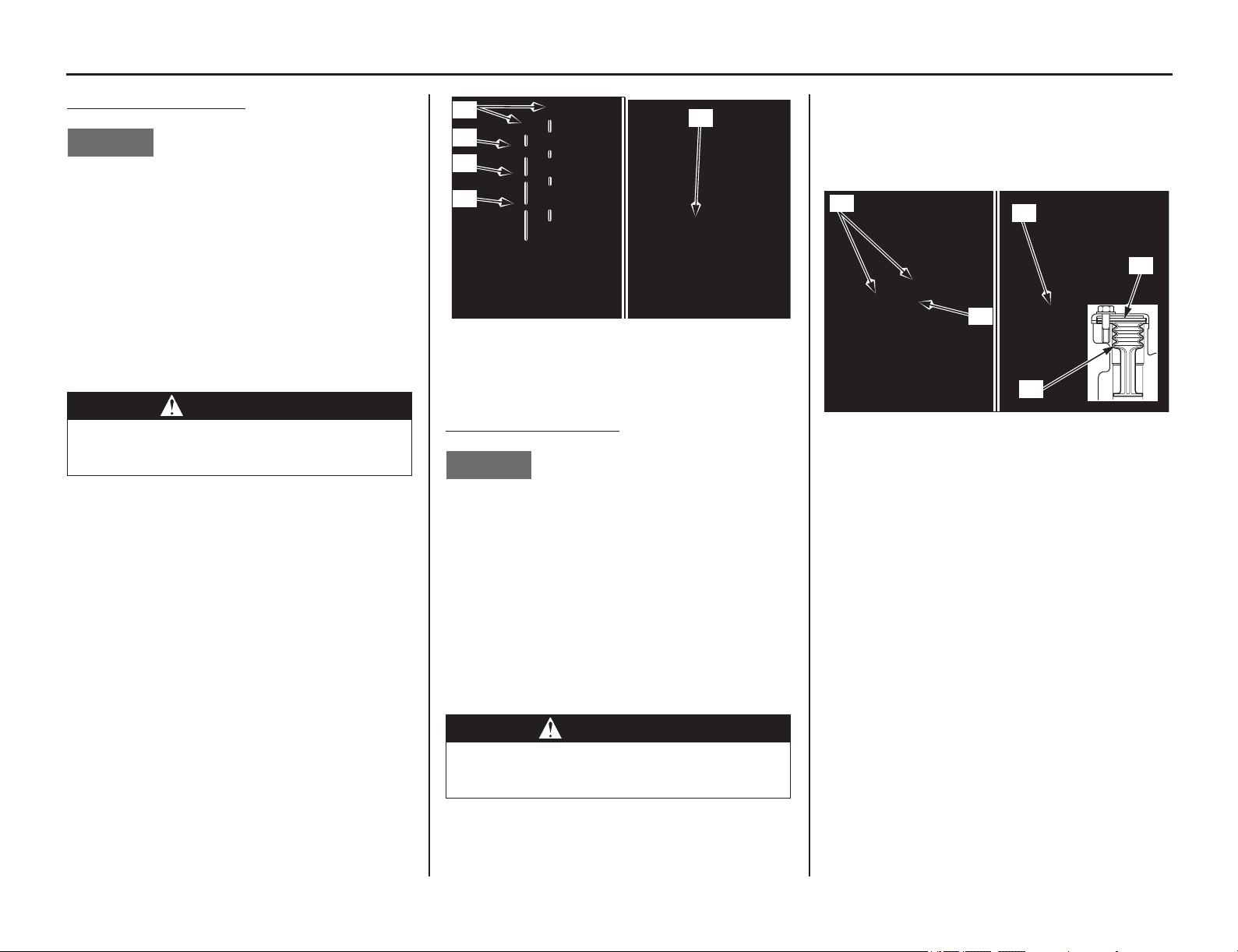
124 Servicing Your Honda
Brakes
Adding Front Brake Fluid
NOTICE
Spilled brake fluid will severely damage painted
surfaces. It is also harmful to some rubber parts.
Be careful whenever you remove the reservoir
cap; make sure the reservoir is horizontal first.
•Always use fresh DOT 4 brake fluid from a
sealed container when servicing the system.
Do not mix different types of fluid, they may
not be compatible.
•The recommended brake fluid is Honda DOT 4
Brake Fluid or an equivalent.
1. Remove the front brake reservoir cap screws
(1), reservoir cap (2), set plate (3) and
diaphragm (4).
2. Fill the reservoir with DOT 4 brake fluid to the
upper level mark (5). Do not overfill.
3. Install the diaphragm and reservoir cap.
4. Tighten the front brake reservoir cap screws to
the specified torque:
0.7 lbf·ft (1.0 N·m, 0.1 kgf·m)
Adding Rear Brake Fluid
NOTICE
Spilled brake fluid will severely damage painted
surfaces. It is also harmful to some rubber parts.
Be careful whenever you remove the reservoir
cap; make sure the reservoir is horizontal first.
•Always use fresh DOT 4 brake fluid from a
sealed container when servicing the system.
Do not mix different types of fluid, they may
not be compatible.
•The recommended brake fluid is Honda DOT 4
Brake Fluid or an equivalent.
1. Remove the rear brake reservoir cap bolts (1),
reservoir cap (2), set plate (3) and diaphragm
(4).
2. Fill the reservoir with DOT 4 brake fluid to the
upper level mark (5). Do not overfill.
3. Install the diaphragm, set plate and reservoir
cap.
4. Tighten the rear brake reservoir cap bolts to the
specified torque:
0.7 lbf·ft (1.0 N·m, 0.1 kgf·m)
WARNING
Clean filler cap before removing. Use only
DOT 4 fluid from a sealed container.
(1) front brake reservoir cap screws
(2) reservoir cap
(3) set plate
(4) diaphragm
(5) upper level mark
WARNING
Clean filler cap before removing. Use only
DOT 4 fluid from a sealed container.
(3)
(2)
(5)
(1)
(4)
(1) rear brake reservoir cap bolts
(2) reservoir cap
(3) set plate
(4) diaphragm
(5) upper level mark
(1)
(2)
(3)
(5)
(4)
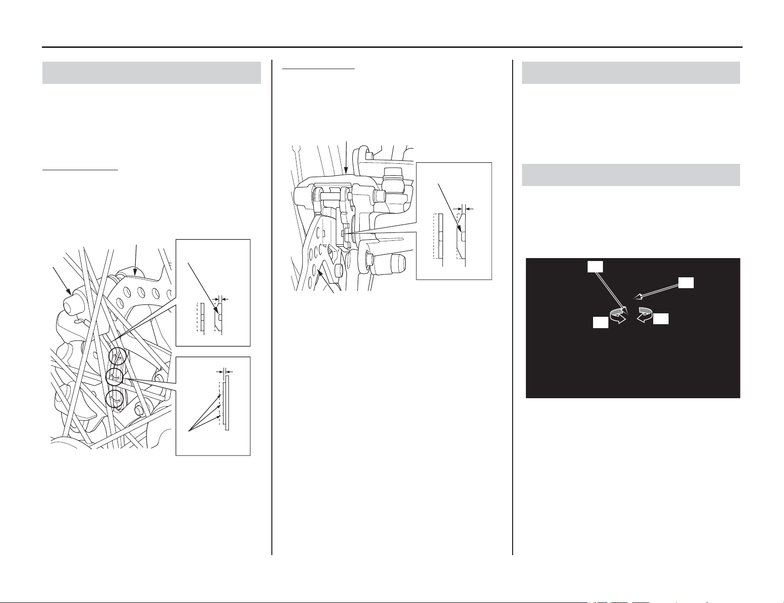
Servicing Your Honda 125
Brakes
Brake pad wear depends on the severity of usage
and track conditions. (Generally, the pads will
wear faster with wet and dirty track conditions.)
Inspect the brake pads at each regular maintenance
interval (pages 36, 37).
Front Brake Pads
Inspect the brake pads (1) through the front wheel
to determine the brake pad wear. If either brake
pad is worn anywhere to a thickness of 0.04 in (1.0
mm), both brake pads must be replaced.
Rear Brake Pads
Inspect the brake pads (1) from the rear side of the
caliper to determine the brake pad wear. If either
brake pad is worn anywhere to a thickness of 0.04
in (1.0 mm), both brake pads must be replaced.
Check that the front brake lever and rear brake
pedal assemblies are positioned properly
(page 122) and the securing bolts are tight.
Make sure there are no fluid leaks. Check for
deterioration or cracks in the hoses and fittings.
Check the operation of the brake light switch (1).
Hold the brake light switch and turn the adjusting
nut (2) in the direction A if the switch operates too
late, or turn the nut in the direction B if the switch
operates too soon.
Brake Pad Wear
(1) brake pads (3) brake disc
(2) front brake caliper
minimum
thickness indicator
0.04 in
(1.0 mm)
0.04 in (1.0 mm)
replace
wear indicator
grooves
(3)
(2)
(1)
(1)
(1) brake pads (3) brake disc
(2) rear brake caliper
minimum
thickness indicator
0.04 in
(1.0 mm)
replace
(3)
(2)
(1)
Other Inspections
Brake Light Adjustment
(1) brake light switch
(2) adjusting nut
(1)
(A)
(2)
(B)
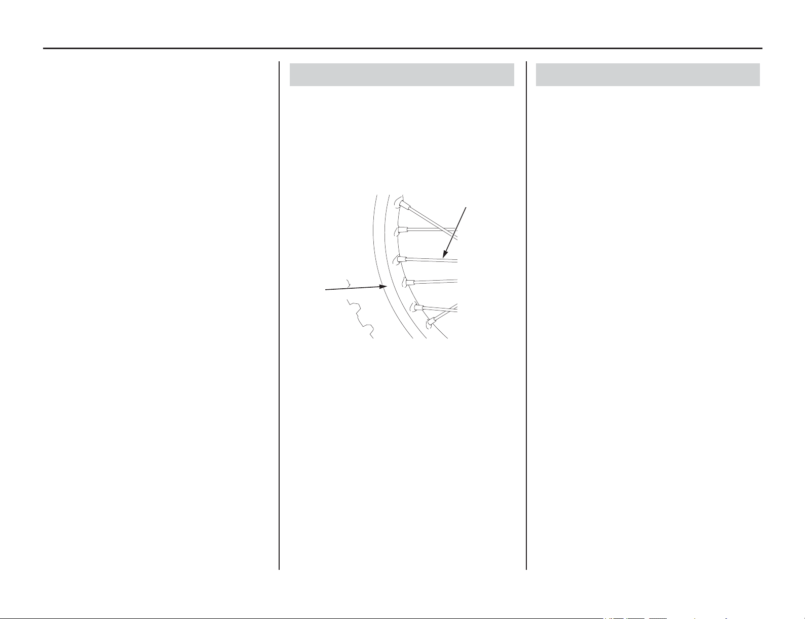
Wheels
126 Servicing Your Honda
Refer to Important Safety Precautions on page 33.
Keeping the wheels true (round) and maintaining
correct spoke tension are critical to safe
motorcycle operation. During the first few rides,
spokes will loosen more rapidly due to the initial
seating
of the parts. Excessively loose spokes may
result in instability at high speeds and the possible
loss of control.
It is not necessary to remove the wheels to perform
the recommended service in the Maintenance
Schedule (pages 36, 37).
However, information for wheel removal is
provided for emergency situations (page 167).
1. Inspect the wheel rims (1) and spokes (2) for
damage.
2. Tighten, any loose spokes to the specified
torque:
Spokes: 2.7 lbf·ft (3.7 N·m, 0.4 kgf·m)
3. Check wheel rim runout. If runout is
noticeable, see an official Honda Service
Manual for inspection instructions.
Also inspect the valve stems for their positions. A
tilted valve stem indicates the tube is slipping
inside the tire or the tire is slipping on the rim. See
your dealer.
See an official Honda Service Manual for
inspection information:
1. Check the axle shaft for runout.
2. Check the condition of the wheel bearings.
Wheel Rims & Spokes
(1) wheel rim (2) spokes
(2)
(1)
Axles & Wheel Bearings
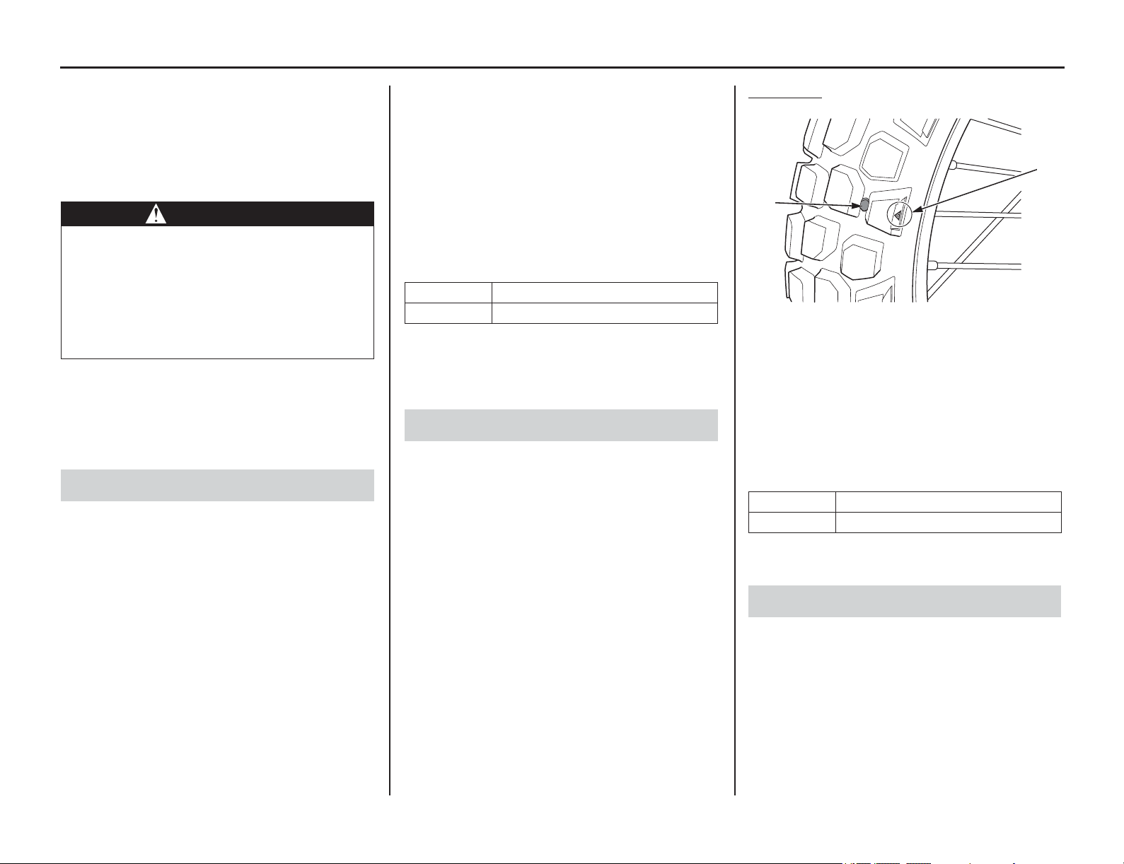
Tires & Tubes
Servicing Your Honda 127
Refer to Important Safety Precautions on page 33.
To
safely operate your motorcycle, your tires must
be the proper type and size, in good condition with
adequate tread, and correctly inflated for the load
you are carrying.
The following pages give detailed information on
how and when to check your air pressure, how to
inspect your tires for wear and damage, and our
recommendations on tire repair and replacement.
Properly inflated tires provide the best
combination of handling, tread life, and riding
comfort. Generally, underinflated tires wear
unevenly, adversely affect handling, and are more
likely to fail from being overheated.
Underinflated tires can also cause wheel damage
on hard terrain. Overinflated tires make your
motorcycle ride harshly, are more prone to damage
from surface hazards, and wear unevenly.
Make sure the valve stem caps are secure. If
necessary, install new caps.
Use an accurate gauge to measure the air pressure
in your tires before each off-road ride and
whenever you return to pavement after riding off-
road. If you only ride on pavement, check the
pressure at least once a month and at any other time
you think the tires might be low.
Always check air pressure when your tires are
“cold.” If you check air pressure when your tires
are “warm” — even if your motorcycle has only
been ridden for a few miles — the readings will be
higher. If you let air out of warm tires to match the
recommended cold pressures, the tires will be
underinflated.
The correct “cold” tire pressures are:
If you decide to adjust tire pressures for a
particular riding condition, make changes a little at
a time.
Take time to inspect your tires and wheels before
you ride.
• Inspect carefully for bumps or bulges in the
side of the tire or the tread. Replace any tire
that has a bump or bulge.
• Look closely for cuts, slits, or cracks in the
tires. Replace a tire if you can see fabric or
cord.
• Check for rocks or other objects embedded in
the tire or tread. Remove any objects.
• Check the position of both valve stems. A
tilted valve stem indicates the tube is slipping
inside the tire or the tire is slipping on the rim.
Tread Wear
Also, if you hit a pothole or hard object while
riding, pull to the side of the road as soon as you
safely can and carefully inspect the tires for
damage.
For the best performance, you should replace a tire
before the tread depth at the center reaches the
following limits:
If the wear indicators are visible, replace the tire
immediately as it is no longer safe.
If a tube is punctured or damaged, you should
replace it as soon as possible. A repaired tube may
not have the same reliability as a new one, and it
may fail while you are riding.
Use a replacement tube equivalent to the original.
WARNING
Using tires that are excessively worn or
improperly inflated can cause a crash in
which you can be seriously hurt or killed.
Follow all instructions in this owner’s
manual regarding tire inflation and
maintenance.
Air Pressure
Front 22 psi (150 kPa, 1.50 kgf/cm
2
)
Rear 22 psi (150 kPa, 1.50 kgf/cm
2
)
Inspection
(1) wear indicator
(2) wear indicator location mark
Front 0.12 in (3.0 mm)
Rear 0.12 in (3.0 mm)
Tube Replacement
(1)
(2)
128 Servicing Your Honda
Tires & Tubes
The tires that came on your motorcycle were
designed to match the performance capabilities of
your motorcycle and provide the best combination
of handling, braking, durability, and comfort.
When replacing, use the original equipment tires or
equivalent tires of the same size, construction,
speed rating, and load range as the originals.
The recommended tires for your motorcycle are:
Whenever you replace a tire, remember:
• Have the wheel balanced after the tire is
installed.
• Have the tire replaced by your dealer if
possible.
• Have a new tube installed whenever a tire is
replaced. The old tube will probably be
stretched. If installed in a new tire, it could fail.
If you have a tire professionally replaced at a non-
Honda facility, we recommend that you have the
work checked by your Honda dealer.
Tire Replacement
WARNING
Installing improper tires on your
motorcycle can affect handling and
stability. This can cause a crash in which
you can be seriously hurt or killed.
Always use the size and type of tires
recommended in this owner’s manual.
Front
80/100-21 M/C 51P
IRC GP-21F
Rear
120/80-18 M/C 62P
IRC GP-22R
Type bias-ply, tube
Side Stand
Servicing Your Honda 129
Refer to Important Safety Precautions on page 33.
• Check that the side stand assembly is working
properly. If the
side stand is stiff or squeaky,
clean the pivot area and lubricate the pivot bolt
with molybdenum grease.
• Check the spring for damage or loss of tension.
• Check the side stand ignition cut-off system:
1. Sit on the motorcycle and put the transmission
in neutral.
2. Raise the side stand.
3. Start the engine.
4. Pull the clutch lever in.
5. Shift the transmission into gear.
6. Lower the side stand all the way.
The engine should stop as you lower the side stand.
If the engine doesn’t stop, see your dealer for
service.
(1) side stand spring
(1)
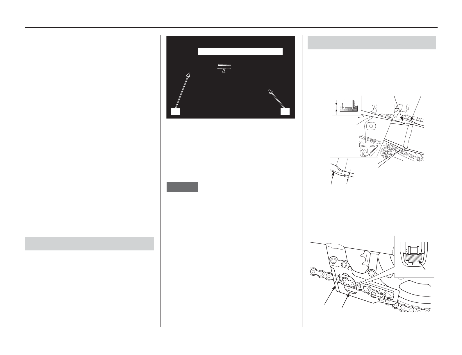
Drive Chain
130 Servicing Your Honda
Drive Chain
Refer to Important Safety Precautions on page 33.
An endless (riveted master link) chain connects the
countershaft and rear wheel sprockets. The O-ring
chain uses rubber rings between the side plates of
the pin and roller links to seal in the manufacturer-
installed lubricating grease and keep out moisture
and dirt.
The service life of the chain depends on proper
lubrication and adjustment. Poor maintenance can
cause premature wear or damage to the drive chain
or sprockets.
When the motorcycle is ridden on unusually dusty
or muddy tracks, more frequent maintenance will
be necessary.
The drive chain should be checked, adjusted, and
lubricated as part of the pre-ride inspection
(page 19).
Under severe usage, or when the motorcycle is
ridden in unusually dusty or muddy areas, more
frequent maintenance will be necessary.
Before servicing your drive chain, turn the engine
OFF, lower the side stand, and check that your
transmission is in neutral.
1. Turn the engine off, raise the rear wheel off the
ground by placing an optional workstand or
equivalent support under the engine and shift
the transmission into neutral.
2. Check the drive chain slack (1) in the upper
drive chain run midway between the drive
sprocket (2) and driven sprocket (3). Drive
chain slack should allow the following vertical
movement by hand:
1 – 1 3/8 in (25 – 35 mm)
3. Check drive chain slack at several points along
the chain. The slack should remain constant. If
it isn’t, some links may be kinked and binding.
Lubricating the chain will often eliminate
binding and kinking.
NOTICE
Excessive chain slack may allow the drive chain to
damage the engine cases.
4. Inspect the drive chain for:
• damaged rollers
•loose pins
• dry or rusted links
• kinked or binding links
• excessive wear
• improper adjustment
• damaged or missing O-rings
Replace the drive chain (page 132) if it has
damaged rollers, loose pins, or kinks that cannot be
free. Lubricate the drive chain (page 131) if it
appears dry or shows signs of rust. Lubricate any
kinked or binding links and work them free.
Adjust chain slack if needed (page 131).
1. Check the chain slider (1) for wear.
Replace it if below the service limit.
SERVICE LIMIT:
upper side: 0.04 in (1.0 mm)
lower side: 0.10 in (2.5 mm)
2. Check the chain guide slider (3) for wear.
Replace the guide slider if it is worn to the
bottom of the wear limit (4).
Inspection
(1) drive chain slack (3) driven sprocket
(2) drive sprocket
(2)
(3)
(1) 1 – 1 3/8 in (25 – 35 mm)
Drive Chain Sliders
(1) chain slider (2) wear indicator
(3) chain guide slider (4) wear limit
0.04 in
(1.0 mm)
0.10 in
(2.5 mm)
(1)
(1)
(2)
(4)
(3)
(4)
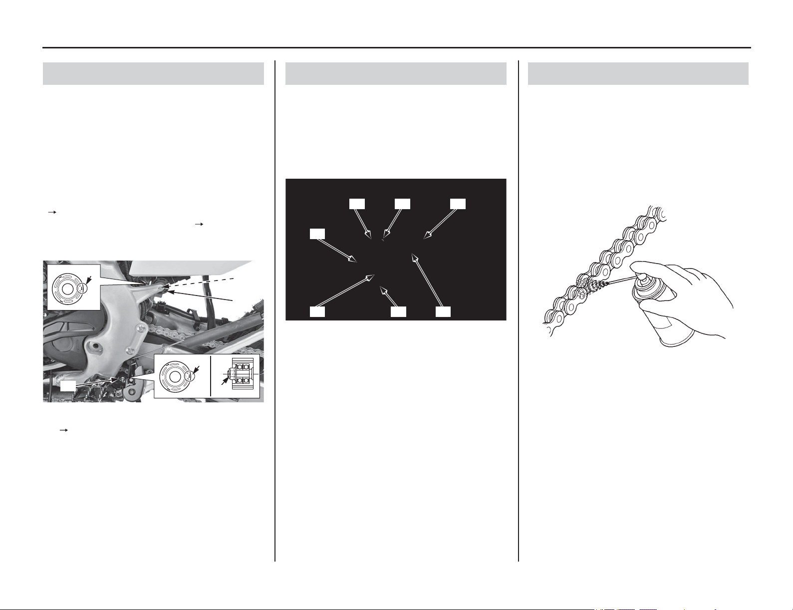
Servicing Your Honda 131
Drive Chain
Check the upper drive chain roller (1) and lower
drive chain roller (2) for wear or damage.
Measure the diameter of the drive chain rollers and
replace them if below the service limit.
Service Limit:
Upper roller: 1.2 in (31 mm)
Lower roller: 1.2 in (31 mm)
Replace the roller if necessary as follows.
Install the upper drive chain roller (Green) with the
“ ” mark (3) facing toward the bracket and lower
drive chain roller (Black) with the “ ” mark facing
toward outside.
Install new a drive chain roller bolt (4) and nut (5).
Clean the threads of the drive chain roller bolt and
apply locking agent to the threads.
Tighten the drive chain roller bolt and nut to the
specified torque:
9 lbf·ft (12 N·m, 1.2 kgf·m)
1. Loosen the rear axle nut (1).
2. Loosen the chain adjuster lock nuts (2) and
turn the adjusting bolts (3) counterclockwise to
decrease slack or clockwise to increase slack.
Align the index marks (4) of the axle plates (5)
with the same reference marks (6) on both
sides of the swingarm.
3. Tighten the rear axle nut to the specified
torque:
94 lbf·ft (128 N·m, 13.1 kgf·m)
4. Recheck chain slack and adjust as necessary.
5. Turn the adjusting bolt counterclockwise until
it touches the axle plates lightly. Then tighten
the chain adjuster lock nuts to the specified
torque while holding the adjusting bolts with a
wrench:
20 lbf·ft (27 N·m, 2.8 kgf·m)
Lubricate the drive chain with Pro Honda HP
Chain Lube or an equivalent chain lubricant or
drive chain lubricant designed specifically for use
with O-ring chains. Wipe off the excess chain
lubricant.
Commercial chain lubricants not designed for
motorcycle drive chains may contain solvents
which could damage the O-rings.
Drive Chain Rollers
(1) upper drive chain roller (Green)
(2) lower drive chain roller (Black)
(3) “ ” mark
(4) drive chain roller bolt (new)
(5) drive chain roller nut
(2)
(1)
(3)
(4)
(3)
(5)
Adjustment
(1) rear axle nut (4) index marks
(2) chain adjuster lock nuts (5) axle plates
(3) adjusting bolts (6) reference marks
(3)(6)(1)
(5)
(6) (4) (2)
Lubrication
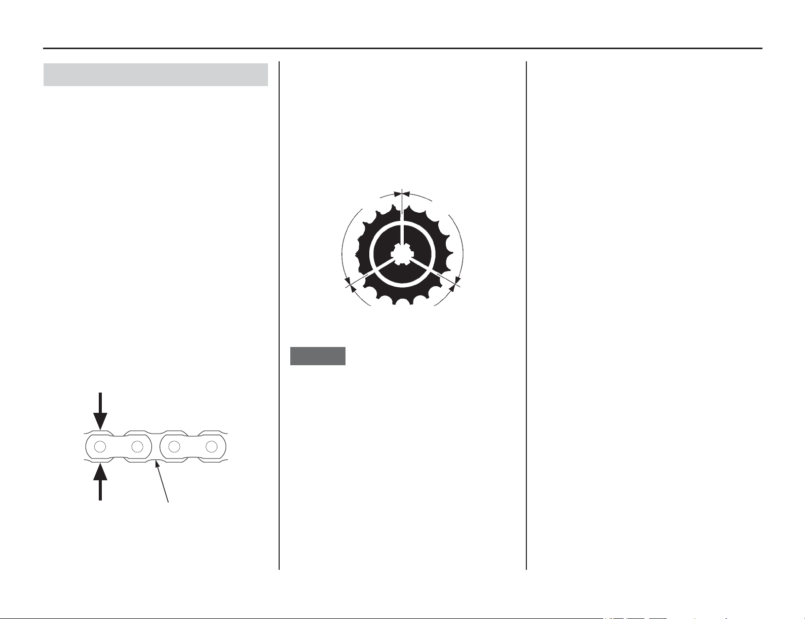
132 Servicing Your Honda
Drive Chain
For maximum service life, the drive chain should
be cleaned, lubricated, and adjusted before each
outing. Your motorcycle has an endless (riveted
master link) type chain. It should only be removed
or replaced by your dealer.
The O-rings can be damaged by steam cleaning,
high pressure washers, and certain solvents.
1. Clean the side surfaces of the chain with a dry
cloth. Use a high flash point solvent such as
kerosene or Pro Honda chain cleaner – not
gasoline. Do not brush the rubber O-rings.
Brushing will damage them. Use of a solvent
may also damage the O-rings.
2. Replace the drive chain if it has damaged
rollers, loose fitting links, damaged O-rings, or
otherwise appears unserviceable.
3. Measure the drive chain plate (1). If the drive
chain plate is worn anywhere to a thickness of
0.52 in (13.3 mm), the drive chain must be
replaced.
Chain:
4. Inspect the sprocket teeth for wear or damage.
We recommend replacing the sprocket
whenever a new chain is installed.
Both chain and sprockets must be in good
condition, or the new replacement chain or
sprocket(s) will wear rapidly.
Excessively worn sprocket teeth have a
hooked, worn appearance. Replace any
sprocket which is damaged or excessively
worn.
NOTICE
Use of a new chain with worn sprockets will cause
rapid chain wear.
5. Lubricate the drive chain (page 131).
6. Recheck chain slack and adjust if necessary.
Removal, Cleaning & Replacement
Size/link:
RK520EXU/116LE
(1) drive chain plate (inner)
(1)
0.52 in (13.3 mm)
Normal Sprocket Teeth
Damaged Sprocket
Teeth
Worn Sprocket
Teeth
REPLACEREPLACE
GOOD
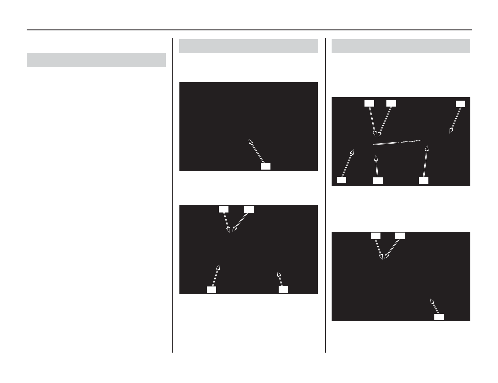
Exhaust Pipe/Muffler
(cont’d)
Servicing Your Honda 133
Refer to Important Safety Precautions on page 33.
Check the mounting bolts and exhaust pipe joint
nut
s for tightness.
Check the exhaust pipe and muffler for cracks or
deformation.
A damaged exhaust pipe and muffler may reduce
engine performance.
1. Remove the seat (page 46).
2. Remove the right side cover (page 47).
3. Loosen the muffler clamp bolt (1).
4. Remove the muffler mounting A bolt (2), B
bolt (3), washer (4), and muffler (5).
1. Remove the gasket (1).
2. Install a new gasket onto the exhaust pipe (2).
3. Align the cutout (3) of the muffler (4) with the
tab (5) of the muffler clamp (6).
4. Install the muffler.
5. Install the washer (7), muffler mounting B bolt
(8)
and A
bolt (9).
Exhaust Pipe/Muffler Inspection
Muffler Removal
(1) muffler clamp bolt
(2) muffler mounting A bolt
(3) muffler mounting B bolt
(4) washer
(5) muffler
(1)
(4)
(3)
(5)
(2)
Muffler Installation
(1) gasket (4) muffler
(2) exhaust pipe (5) tab
(3) cutout (6) muffler clamp
(7) washer
(8) muffler mounting B bolt
(9) muffler mounting A bolt
(4)
(6)
(2)
(3)
(1)
(5)
(7)
(8)
(9)
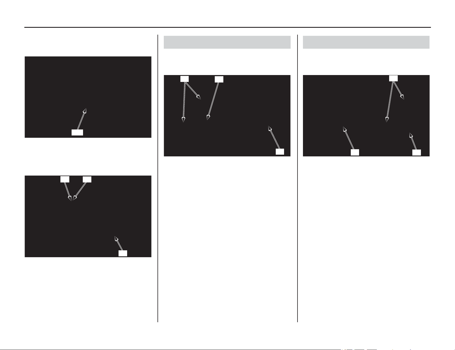
134 Servicing Your Honda
Exhaust Pipe/Muffler
6. Tighten the muffler clamp bolt (10) to the
specified torque:
15 lbf·ft (20 N·m, 2.0 kgf·m)
7. Tighten the muffler mounting B bolt (8) and A
bolt (9) to the specified torque:
19 lbf·ft (26 N·m, 2.7 kgf·m)
8. Install the right side cover (page 47).
9. Install the seat (page 46).
1. Remove the muffler (page 133).
2. Remove the exhaust pipe joint nuts (1),
exhaust pipe (2) and gasket (3).
1. Install a new exhaust pipe gasket (1).
2. Install the exhaust pipe (2) and exhaust pipe
joint nuts (3) but do not tighten the nuts yet.
3. Install the muffler (page 133) but do not
tighten the bolts yet.
4. Tighten the exhaust pipe joint nuts to the
specified torque:
16 lbf·ft (22 N·m, 2.2 kgf·m)
5. Tighten the muffler clamp bolt, muffler
mounting A bolt and B bolt (page 133).
(10) muffler clamp bolt
(7) washer
(8) muffler mounting B bolt
(9) muffler mounting A bolt
(10)
(7)
(8)
(9)
Exhaust Pipe Removal
(1) exhaust pipe joint nuts
(2) exhaust pipe
(3) gasket
(2)
(3)
(1)
Exhaust Pipe Installation
(1) exhaust pipe gasket (new)
(2) exhaust pipe
(3) exhaust pipe joint nuts
(2)
(1)
(3)

Spark Arrester
Servicing Your Honda 135
The spark arrester must be serviced every 1,000 mi
(1,600 km) of running or 100 operating hours to
maintain its efficiency.
Regular servicing prevents carbon buildup (which
can diminish engine performance) and also
complies with USDA regulations for regular
maintenance to assure proper function.
The spark arrester prevents random sparks from
the combustion process in your engine from
reaching the environment.
1. Allow the engine and muffler (1) to cool.
2. Remove the tail cap cover bolts (2), washers
(3) and tail cap cover (4) from the muffler.
3. Remove the spark arrester mounting bolts (5),
spark arrester (6) and gasket (7) from the
muffler (1).
4. Use a brush to remove carbon deposits from
the spark arrester screen. Be careful to avoid
damaging the spark arrester screen (8). The
spark arrester must be free of breaks and holes.
Replace, if necessary.
Check the gasket. Replace, if necessary.
5. Install a new gasket (7) and the spark arrester
(6)
in the muffler (1) and tighten the spark
arrester mounting bolt
s (5) to the specified
torque:
6.6 lbf·ft (9.0 N·m, 0.9 kgf·m)
6. Install the tail cap cover (4), washers (3) and
tighten the tail cap cover bolts (2) to the
specified torque:
3.9 lbf·ft (5.25 N·m, 0.5 kgf·m)
Spark Arrester Inspection
(1) muffler
(2) tail cap cover bolts
(3) washers
(4) tail cap cover
(1)
(2)
(2)
(4)
(3)
(3)
(2)
(3)
(1) muffler
(5) spark arrester mounting bolts
(6) spark arrester
(7) gasket
(8) spark arrester screen
(1)
(5)
(7)(6)(5)
(8)
(1) muffler
(5) spark arrester mounting bolts
(6) spark arrester
(7) gasket
(1) muffler
(2) tail cap cover bolts
(3) washers
(4) tail cap cover
(1)
(5)
(7)(6)(5)
(1)
(2)
(2)
(4)
(3)
(3)
(2)
(3)
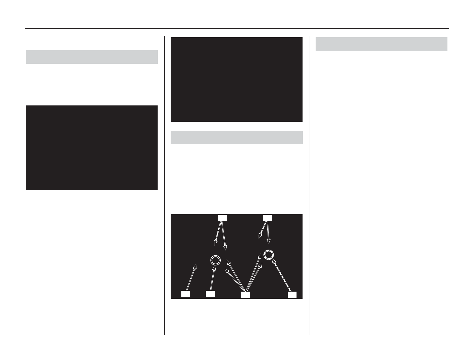
Additional Maintenance Procedures
136 Servicing Your Honda
Additional Maintenance Procedures
Refer to Important Safety Precautions on page 33.
1. With your motorcycle on an optional
workstand or equivalent support (front wheel
elevated), turn the handlebar to the right and
left to check for roughness in the steering head
bearings.
2. Stand in front of your motorcycle, grab the
fork (at the axle), look at the steering head, and
push the fork in and out (toward the engine) to
check for play in the steering head bearings.
If any roughness or play is felt, but you do not see
any movement in the steering head, the fork
bushings may be worn.
Refer to an official Honda Service Manual for
replacement or adjustment procedures, or see your
dealer.
1. Check the handlebar (1) for bends or cracks.
2. Check that the handlebar has not moved from
its original position where the end of the
handlebar holders (2) is aligned with the paint
marks (3).
3. Check the torque of the handlebar upper holder
bolts (4):
16 lbf·ft (22 N·m, 2.2 kgf·m)
Tighten the front bolts first.
Periodically, disconnect the clutch cables at their
upper ends. Thoroughly lubricate the cable pivot
points with a commercially available cable
lubricant. If the clutch lever and throttle operation
is not smooth, replace the cable.
Be sure the throttle returns freely from fully open
to fully closed automatically, in all steering
positions.
Steering Head Bearing Inspection
Handlebar Inspection
(1) handlebar
(2) handlebar holders
(3) paint marks
(4) handlebar upper holder bolts
(1)
(4)
(3)
(2)
(4)
(3)
Control Cables

Servicing Your Honda 137
Additional Maintenance Procedures
Check and tighten nuts, bolts, and fasteners before
every outing.
RIGHT SIDE LEFT SIDE
Nuts, Bolts, Fasteners
ENGINE
Item
Torque
lbf·ft N·m kgf·m
1 Cylinder head cover
socket bolts 7 10 1.0
2 Clutch cover bolts 7 10 1.0
3 Water pump cover bolts 7 10 1.0
4 Crankshaft hole cap 11 15 1.5
5 Oil filter cover bolts 7 10 1.0
6 Cylinder head bolts 37 50 5.1
7 Exhaust pipe joint nuts 16 22 2.2
8 Drive sprocket bolt 23 31 3.2
9 Engine oil drain bolt 13 18 1.8
10 Coolant drain bolt 7 10 1.0
(1) cylinder head cover socket bolts
(2) clutch cover bolts
(3) water pump cover bolts
(4) crankshaft hole cap
(6) cylinder head bolts
(7) exhaust pipe joint nuts
(10) coolant drain bolt
(3)
(4) (10)
(6)
(1)
(7)
(2)
(1) cylinder head cover socket bolts
(5) oil filter cover bolts
(6) cylinder head bolts
(8) drive sprocket bolt
(9) engine oil drain bolt
(6)
(9)
(1)
(8)
(5)
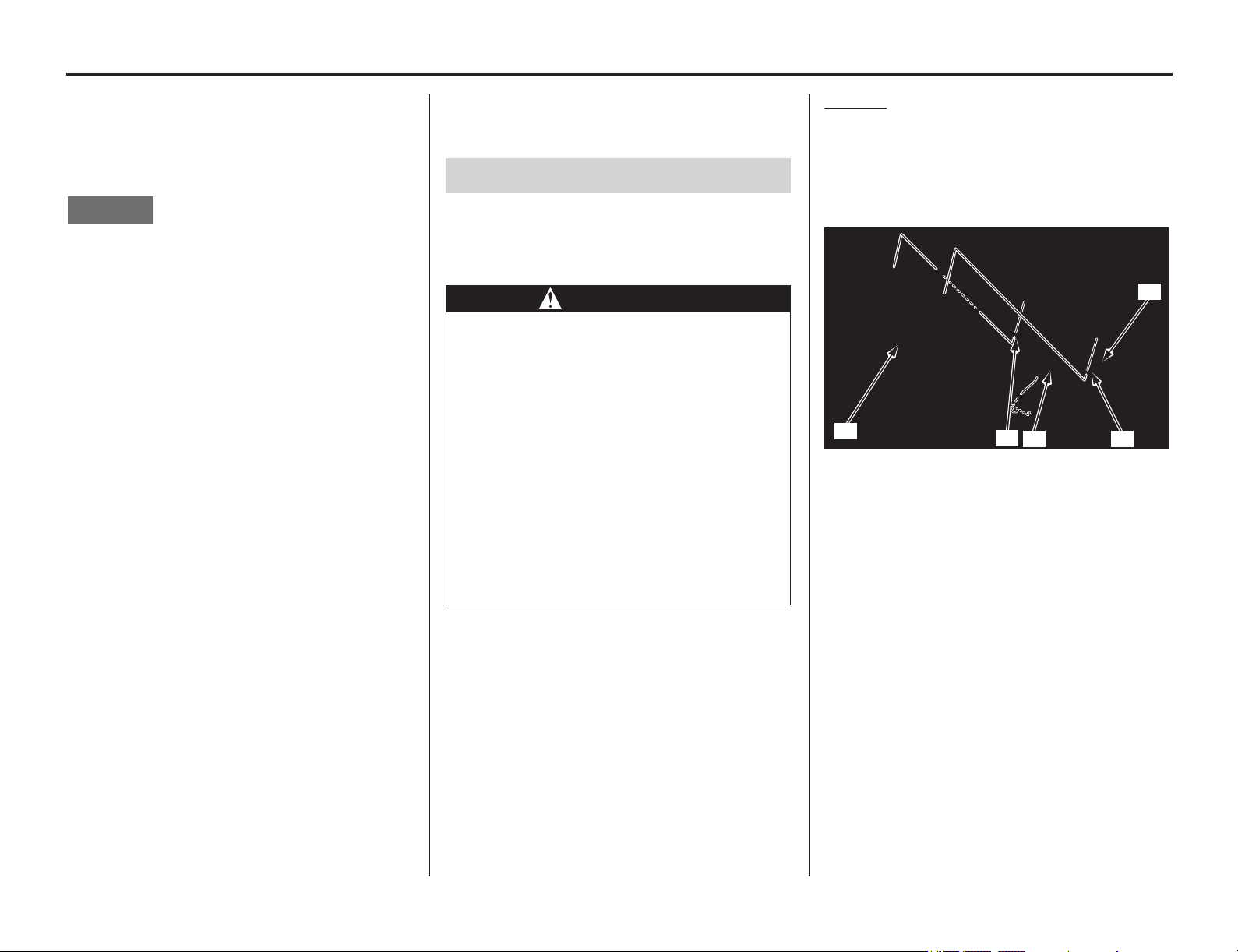
Battery
138 Servicing Your Honda
Refer to Important Safety Precautions on page 33.
Your
motorcycle has a lithium-ion (li-ion) battery.
Clean the battery terminals if they become dirty or
corroded.
NOTICE
An improperly disposed of battery can be harmful
to the environment and human health.
Always confirm local regulations for proper
battery disposal instruction.
The electrical accessories use current from the
battery, even when the ignition is turned to the
OFF position.
Limited operation also allows the battery to
discharge. If you have electrical accessories on
your motorcycle or do not ride frequently, we
recommend that you charge the battery frequently
(see Battery Charging on page 139).
If you plan to store your motorcycle, see Battery
Storage (this page).
If your battery seems weak and/or is leaking
electrolyte (cause slow starting), see your dealer.
If you smell an unusual odor coming from the
lithium-ion (li-ion) battery, park your motorcycle
in a safe place outside and away from flammable
objects, then turn the ignition to the OFF position.
The battery has a limited life span.
Consult your dealer about when you should
replace the battery. Always replace the battery
with another lithium-ion (li-ion) battery of the
same type.
The lithium-ion (li-ion) battery contains a fuse
inside.
If the fuse blows, the battery needs replacement.
The voltage may read above 12V even with a
blown battery fuse when the battery is unmounted
(page 175).
Before you remove the battery, be sure to read all
the information that follows, as well as the
information on the battery label.
If you do not remove the battery, we recommend
disconnecting the battery cables (negative cable
first).
The battery is located under the seat.
Removal
1. Remove the seat (page 46).
2. Remove the battery band (1).
3. Remove the positive terminal cover (2).
4. Disconnect the negative (–) terminal (3) first,
then the positive (+) terminal (4) and remove
the battery (5).
5. Unless you have been riding regularly, charge
the battery (page 139).
6. Store your battery in an easy-to-reach location
off the floor, in an area protected from freezing
temperatures and direct sunlight.
7. Clean the battery box after removing the
battery for storage. Dry the battery box.
8. Slow charge the battery (page 139) once every
30 days.
Battery Storage
WARNING
The battery contains flammable organic
solvent as electrolyte.
You can be burned or seriously injured if
the battery is handled improperly.
• Keep the battery away from heat,
sparks, and flame.
• Keep the battery out of the reach of
children.
• Do not disassemble or modify the
battery or battery terminals.
• Do not short-circuit the battery with
metal tools or other metal objects.
• Do not subject the battery to impacts.
(1) battery band (4) positive (+) terminal
(2) positive terminal cover (5) battery
(3) negative (–) terminal
(3)
(2)
(4)(1)
(5)
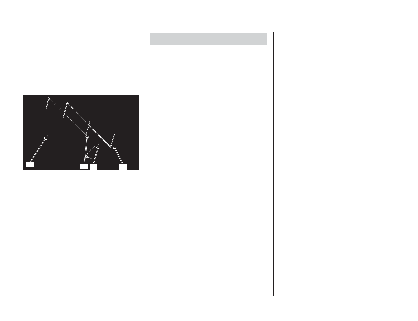
Servicing Your Honda 139
Battery
Installation
1. Reinstall the battery (1) in the reverse order of
removal. Check that the battery rubber in
place. Be sure to connect the positive (+)
terminal first, then the negative (–) terminal.
2. Tighten the positive (+) terminal bolt (2) and
negative (–) terminal bolt (3) to the specified
torque:
1.5 lbf·ft (2.0 N·m, 0.2 kgf·m)
3. Install the battery band (4).
Be sure to read the information that came with
your battery charger and follow the instructions on
the battery. Improper charging may damage the
battery.
We recommend using a charger recommended by
your lithium-ion (li-ion) battery manufacturer
which can be purchased from your dealer. These
units can be left connected for long periods without
risking damage to the battery. However, the
lithium-ion (li-ion) battery may degrade if stored
with a charger connected. Do not intentionally
leave the charger connected longer than the time
period recommended in the charger’s instructions.
Using a battery charger that is not recommended
can cause permanent damage to your battery.
(1) battery (3)
negative (–) terminal bolt
(2)
positive (+) terminal bolt
(4) battery band
(3)
(1)(4)
(1)
Battery Charging
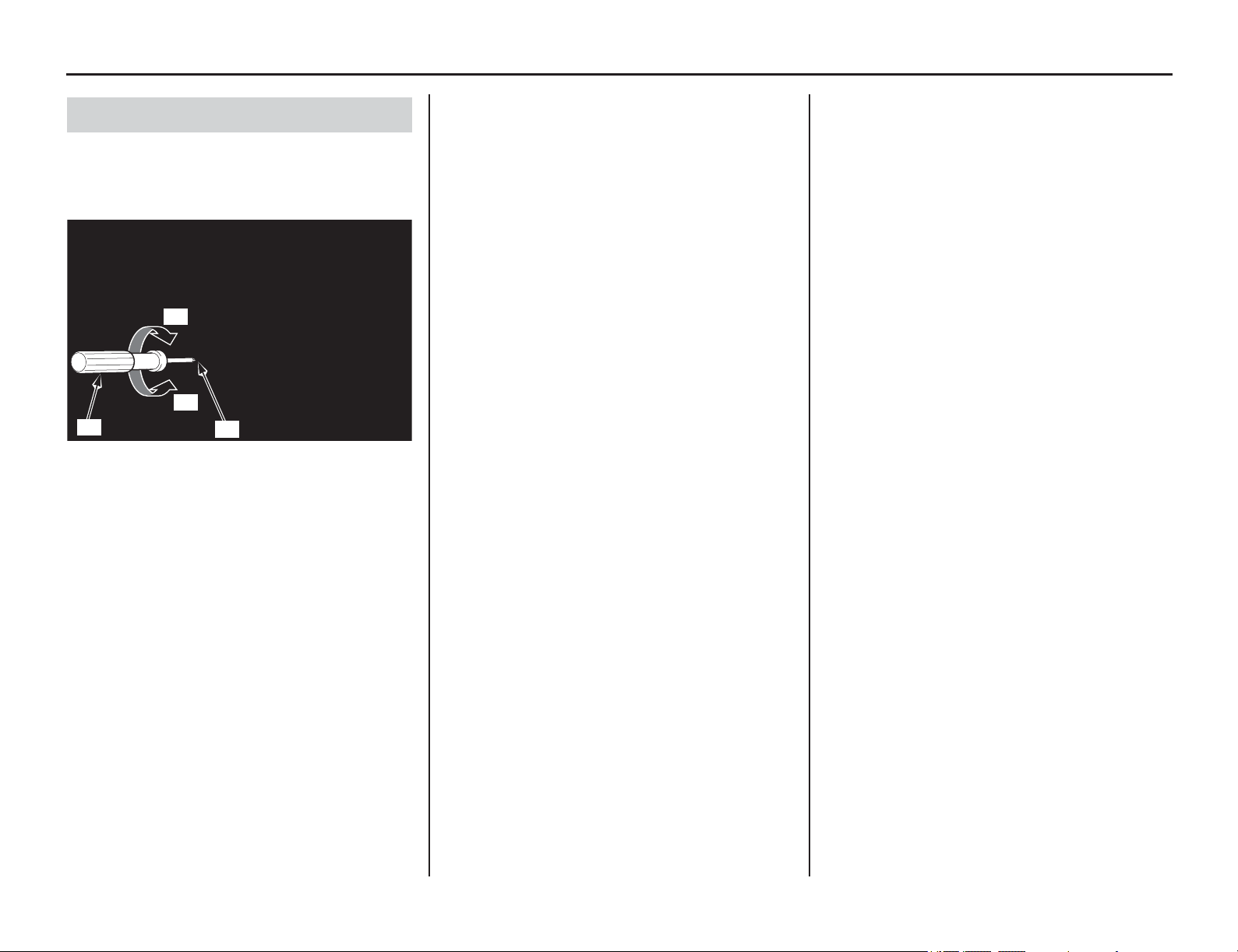
Headlight Aim
140 Servicing Your Honda
Headlight Aim
You can adjust vertical aim of the headlight for
proper alignment. Turn the screw (1) in or out as
necessary using a Phillips screwdriver (2). Obey
local laws and regulations.
Headlight Aim Vertical Adjustment
(1) screw (A) Up
(2) Phillips screwdriver (B) Down
(1)
(2)
(A)
(B)
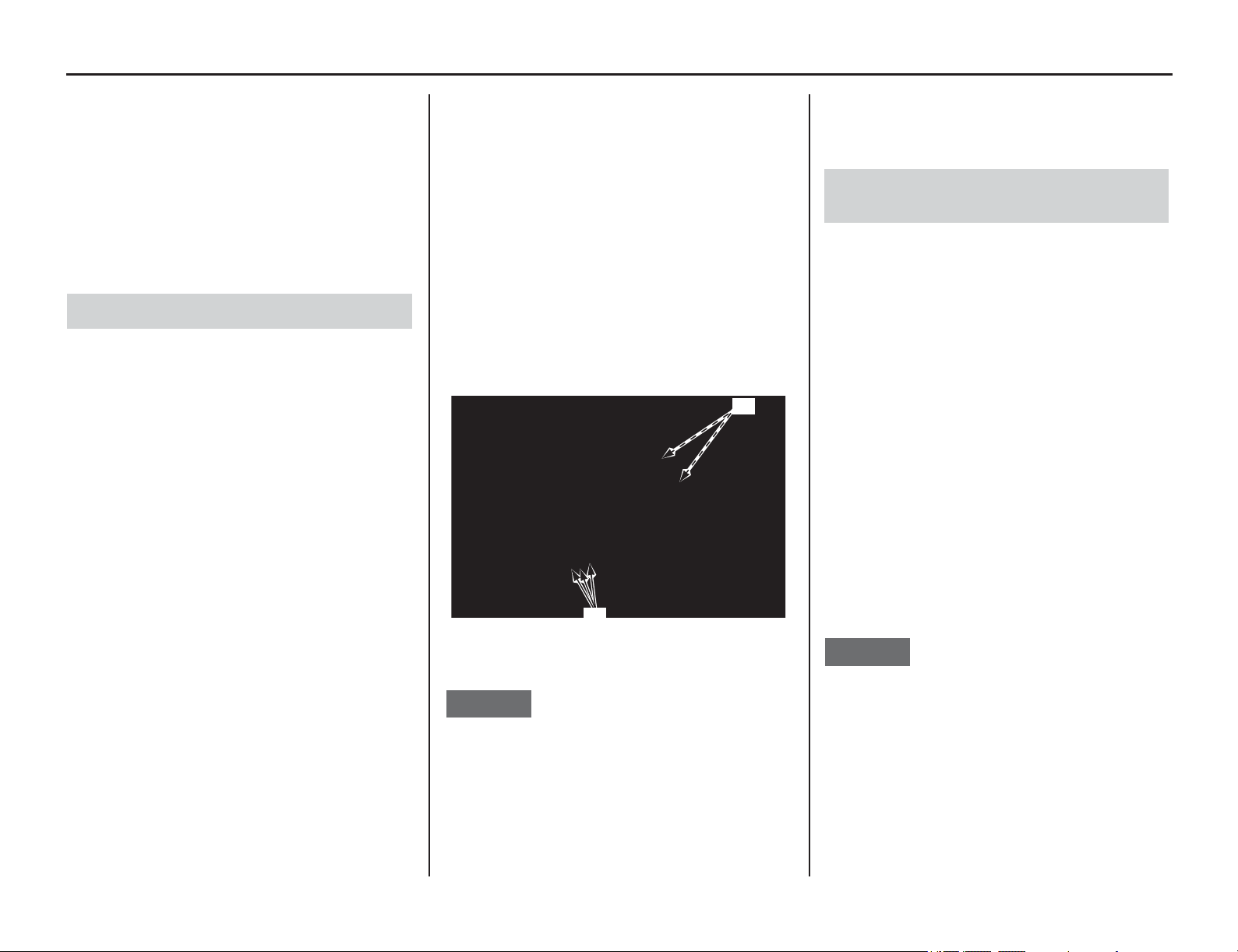
Appearance Care
(cont’d)
Servicing Your Honda 141
Refer to Important Safety Precautions on page 33.
Frequent
cleaning and polishing will keep your
motorcycle looking newer longer. Frequent
cleaning also identifies you as an owner who
values his motorcycle. A clean motorcycle is also
easier to inspect and service.
While you’re cleaning, be sure to look for damage,
wear, and gasoline or oil leaks.
• To clean your motorcycle you may use:
–water
– Hondabrite
– a mild, neutral detergent and water
– a mild spray and wipe cleaner/polisher
– a mild spray and rinse cleaner/degreaser and
water
• Avoid products that contain harsh detergents
or chemical solvents that could damage the
metal, paint, and plastic on your motorcycle or
discolor the seat and decals.
• If your motorcycle is still warm from recent
operation, give the engine and exhaust system
time to cool off.
• Park in a shady area. Washing your motorcycle
in bright sunlight may cause the finish to fade
because water droplets intensify the sun’s
brightness. Spotting is also more likely
because surface water can dry before you have
time to wipe it off.
• Clean your motorcycle regularly to protect
surface finishes.
• We recommend the use of a low pressure
garden hose to wash your motorcycle. High
pressure washers (like those at coin-operated
car washes) can damage certain parts of your
motorcycle. The force of water under extreme
pressure can penetrate the dust seals of the
suspension pivot points and steering head
bearings-driving dirt inside and needed
lubrication out.
If you use a high pressure washer, avoid spraying
the following areas:
brake master cylinders
drive chain
electrical circuit
engine stop button
muffler outlet
steering head bearings
suspension pivot points
throttle body
under fuel tank
under seat
NOTICE
High pressure water (or air) can damage certain
parts of your motorcycle.
You may use Pro Honda Hondabrite, a multi-
surface cleaner/degreaser, to remove both dirt and
petroleum-based grime from paint, alloy, plastic,
and rubber surfaces. Wet any heavy deposits with
water first. Then spray on Pro Honda Hondabrite
and rinse with a low pressure garden hose at full
pressure. Stubborn deposits may require a quick
wipe with a sponge.
Allow the engine, muffler, brakes, and other high-
temperature parts to cool before washing.
1. Rinse your motorcycle thoroughly using a low
pressure garden hose to remove loose dirt.
2. Fill a bucket with cool water. Mix in a mild,
neutral detergent, such as dish washing liquid
or a product made especially for washing
motorcycles or automobiles.
3. Wash your motorcycle with a sponge or a soft
towel.
As you wash, check for heavy grime. If
necessary, use a mild cleaner/degreaser to
remove the grime.
The headlight's inside lens may fog
temporarily after washing or while riding in
the rain. This does not impact the headlight
function.
However, if you see a large amount of water or
ice accumulated inside the lens, have your
vehicle inspected by your dealer.
NOTICE
Do not use steel wool to clean the frame as it could
damage or discolor the frame surface.
Muffler stain remover (Scotch Brite Hand Pad
#7447-maroon) is for removing stains on the non-
coated aluminum frame only.
4. After washing, rinse your motorcycle
thoroughly with plenty of clean water to
remove any residue.
Detergent residue can corrode alloy parts.
General Recommendations
(1) steering head bearings
(2) suspension pivot points
(1)
(2)
Washing Your Motorcycle with a Mild
Detergent
142 Servicing Your Honda
Appearance Care
5. Dry your motorcycle with a chamois or a soft
towel.
Leaving water on the surface to air dry can
cause dulling and water spots. As you dry,
inspect for chips and scratches.
6. Lubricate the drive chain to prevent rusting.
7. Start the engine and let it idle for several
minutes. The engine heat will help dry moist
areas.
8. As a precaution, ride at a slow speed and apply
the brakes several times. This will help dry the
brakes and restore normal braking
performance.
There are some things you should do just after
washing your motorcycle to help prevent rust and
corrosion.
Once your motorcycle is clean and dry, you should
protect any bare steel from rusting by applying a
light coating of a rust-inhibitor. Lubricate the drive
chain and drive sprocket after removing and
thoroughly cleaning in solvent. Be sure the chain is
wiped clean and is dry before applying the chain
lube.
Follow the suggestions given in the pages of this
manual for lubricating items such as the brake and
clutch lever pivot points and footpeg pivot pins.
Follow these guidelines to prevent scratches and
blemishes:
• Wash gently using a soft sponge and plenty of
water.
• To remove stubborn stains, use diluted
detergent and rinse thoroughly with plenty of
water.
• Avoid getting gasoline, brake fluid, or
detergents on the instruments, panels, or
headlight.
Aluminum corrodes when it comes in contact with
dust, mud and road salt.
To remove stains, use Scotch Brite Hand Pad
#7447 (maroon) or an equivalent.
Wet the pad and polish the surface using strokes
parallel to the length of the frame.
Clean the frame using a wet sponge and a mild
detergent, then rinse well with clean water. Dry the
frame with a soft clean cloth, using strokes parallel
to the length of the frame.
NOTICE
Do not use steel wool to clean the frame as it could
damage or discolor the frame surface.
Scotch Brite Hand Pad #7447-maroon is for
removing stains on the non-coated aluminum
frame only.
The fuel tank is made of titanium material.
To remove mud or dust, use a sponge or soft cloth
and a stainless steel kitchen detergent, then rinse
well with clean water.
After washing, rinse with plenty of water and dry
with a clean cloth.
The exhaust pipe and muffler are stainless steel but
may became stained by mud or dust.
To remove mud or dust, use a wet sponge and a
liquid kitchen abrasive, then rinse well with clean
water. Dry with chamois or a soft towel.
If necessary, remove heat stains by using a
commercially available fine texture compound.
Then rinse by the same manner as removing mud
or dust.
After Cleaning Lubrication
Panels
Aluminum Frame Maintenance
Titanium Fuel Tank Maintenance
Exhaust Pipe and Muffler Maintenance

Adjustments
Adjustments 143
This section
tells you how to fine tune your
motorcycle for maximum performance.
Off-Road Use
only
Initial suspension adjustments should be
performed after a minimum of 2 hours of easy
break-in time.
Follow the instructions given in the rear
suspension sag setting section of Rear Suspension
Adjustments to determine if your combined rider
and sprung machine weight (rider fully dressed for
competition and machine coolant, oil and fuel
levels ready for competition).
Front Suspension Adjustments ......................144
Front Suspension Air Pressure...................144
Front Suspension Damping........................145
Rear Suspension Adjustments........................146
Rear Suspension Spring Pre-Load
(Off-Road Use Only) .................................146
Rear Suspension Damping.........................147
Rear Suspension Race Sag
(Off-Road Use Only) .................................148
Suspension Adjustment Guidelines
(Off-Road Use Only) .....................................150
Tuning Tips....................................................153
Spark Plug Reading (Off-Road Use Only)...153
Chassis Adjustments ......................................154
Rear End (Off-Road Use Only) .................154
Fork Height/Angle (Off-Road Use Only)....154
Wheelbase (Off-Road Use Only)...............154
Tire Selection for Track Conditions
(Off-Road Use Only) .....................................155
Personal Fit Adjustments ...............................156
Control Positioning (Off-Road Use Only) ...156
Handlebar Position (Off-Road Use Only) ....156
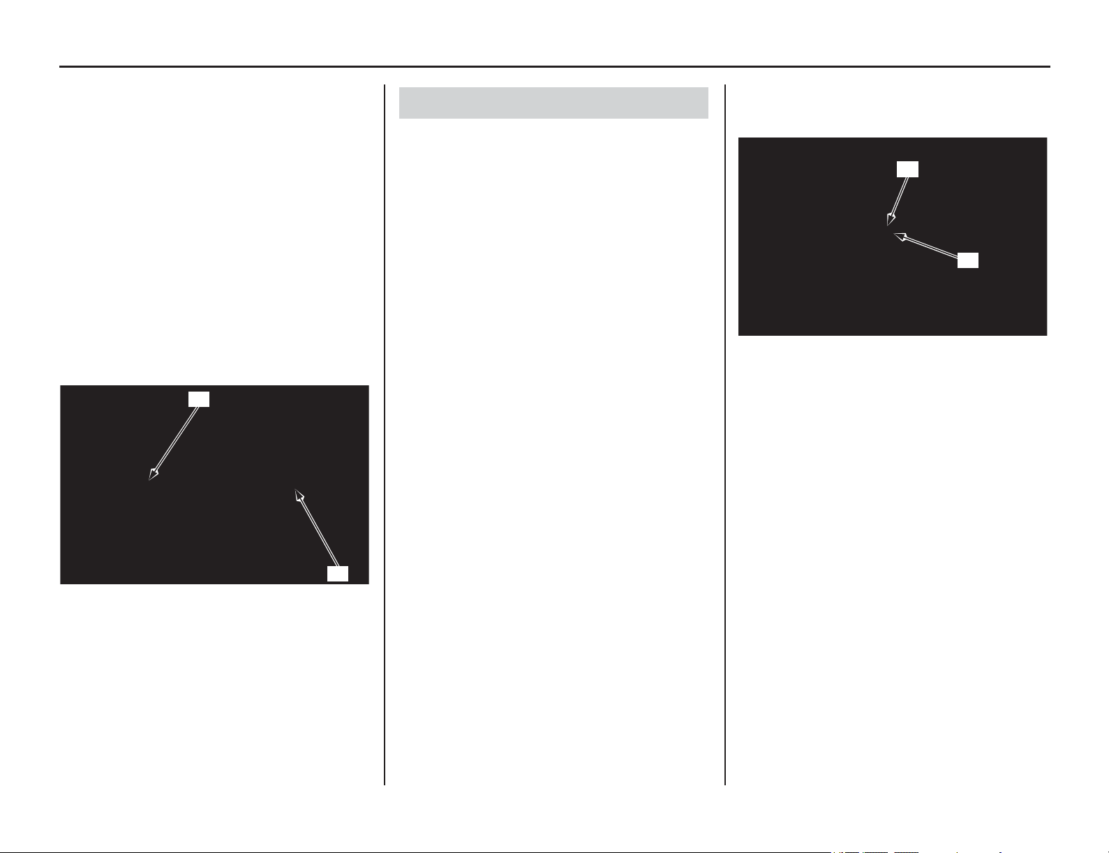
Front Suspension Adjustments
144 Adjustments
Front Suspension Adjustments
The front suspension can be adjusted for the rider's
weight and riding conditions by using one or more
of the following methods:
• Compression damping — Turning the
compression damping adjuster (1) adjusts how
quickly the fork compresses.
• Rebound damping — Turning the rebound
damping adjuster (2) adjusts how quickly the
fork extends.
The inverted fork on your motorcycle features
sealed damper cartridges with dual (separate air
and oil) chambers to prevent aeration. The design
also isolates the oil in each fork/damper, which
may contain air bubbles and/or metal particles,
from the sealed cartridge to provide more
consistent damping.
Air is an unstable gas which builds up pressure as it
is worked (such as in a fork). Air pressure acts as a
progressive spring and affects the entire range of
fork travel. This means the fork action on your
motorcycle will get stiffer during a race. For this
reason, release built-up air pressure in the fork legs
between race. Be sure the fork is fully extended with
the front tire off the ground when you release the
pressure.
The standard air pressure is 0 psi (0 kPa, 0 kgf/cm
2
).
You may relieve accumulated air pressure in the fork
legs by using the pressure release screws. The front
wheel should be off the ground before you release the
pressure. The air pressure should be adjusted
according to the altitude and outside temperature.
1. Place an optional workstand under the engine,
so that the front wheel is off the ground.
Do not adjust air pressure with the front wheel
on the ground as this will give false pressure
readings.
2. Remove the pressure release screw (1).
3. Apply recommended fork oil to a new O-ring
(2), and then install a new O-rings.
4. Install and tighten the pressure release screw to
the specified torque:
1.0 lbf·ft (1.3 N·m, 0.1 kgf·m)
(1) compression damping adjuster
(2) rebound damping adjuster
(1)
(2)
Front Suspension Air Pressure
(1) pressure release screw (2) O-ring (new)
(2)
(1)
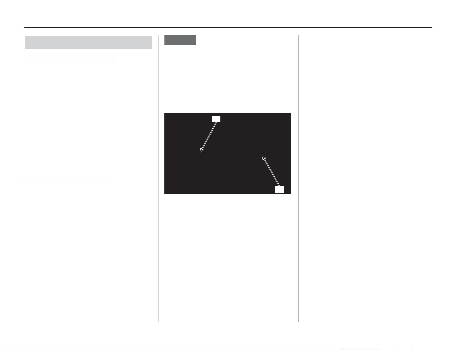
Adjustments 145
Front Suspension Adjustments
Compression Damping Adjustment
This adjustment affects how quickly the fork
compresses. The fork compression damping
adjuster has 16 clicks or more. Turning the
compression damping adjuster screw (1) one full
turn changes the adjuster 4 clicks. To adjust the
adjuster to the standard position, proceed as
follows:
Turn the adjuster clockwise (harder) until it will no
longer turn (lightly seats). Turn the adjuster
counterclockwise (softer) until it clicks. This click
is position 1.
The standard position is 7 clicks.
Make sure that both fork legs are adjusted to the
same position.
Rebound Damping Adjustment
The fork rebound damping adjuster has 16 clicks
or more. Turning the rebound damping adjuster
screw (2) one full turn clockwise advances the
adjuster 4 clicks. To adjust the rebound damping to
the standard setting, proceed as follows:
Turn the adjuster clockwise (harder) until it will no
longer turn (lightly seats). Turn the adjuster
counterclockwise (softer) until it clicks. This click
is position 1.
The standard position is 12 clicks.
Make sure that both fork legs are adjusted to the
same position.
NOTICE
Always start with full hard when adjusting
damping.
Do not turn the adjuster screw more than the given
positions or the adjuster may be damaged.
Be sure that the compression and rebound
adjusters are firmly located in a detent, and not
between positions.
Both compression and rebound damping can be
increased by turning the adjuster clockwise.
Front Suspension Damping
(1) compression damping adjuster screw
(2) rebound damping adjuster screw
(1)
(2)
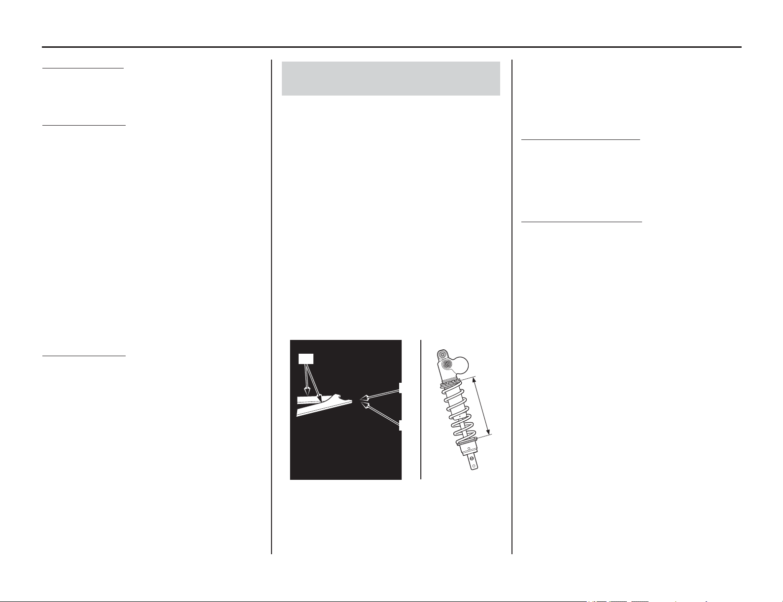
Rear Suspension Adjustments
146 Adjustments
Rear Suspension Adjustments
On-Road Use
only
The rear suspension can be adjusted for the rider’s
weight and riding conditions by changing the
rebound and compression damping.
Off-Road Use
only
The rear suspension can be adjusted for the rider’s
weight and riding conditions by changing the
spring pre-load and the rebound and compression
damping.
The rear suspension assembly includes a damper
unit that contains high pressure nitrogen gas. Do
not attempt to disassemble, service, or dispose of
the damper; see your dealer. The instructions
found in this owner’s manual are limited to
adjustments of the shock assembly only.
Puncture or exposure to flame may also result in an
explosion, causing serious injury.
Service or disposal should only be done by your
dealer or a qualified mechanic, equipped with the
proper tools, safety equipment and an official
Honda Service Manual.
Off-Road Use
only
If your motorcycle is new, put enough part-throttle
break-in time (about 1 hour) on it to ensure that the
suspension has worked in.
Pre-load should be adjusted when the engine is
cold because it is necessary to remove the muffler.
An optional pin spanner is available for turning the
shock spring lock nut and adjusting nut to adjust
spring pre-load.
1. Place your motorcycle on an optional
workstand or equivalent support with the rear
wheel off the ground.
2. Remove the subframe (page 52).
3. Check that the spring pre-load is adjusted to
the standard length. Adjust as necessary by
loosening the shock spring lock nut (1) and
turning the adjusting nut (2).
Each complete turn of the adjusting nut
changes the spring length by 0.06 in (1.5 mm).
After adjustment, hold the adjusting nut and
tighten the shock spring lock nut to the
specified torque:
32 lbf·ft (44 N·m, 4.5 kgf·m)
Refer to the following pages for the installation
procedure of the removed parts:
• air cleaner housing and air cleaner connecting
tube: page 58 (Cylinder Head Installation)
• subframe: page 55
To increase spring pre-load
Loosen the shock spring lock nut with the optional
pin spanners (3) and turn the adjusting nut to
shorten the spring length (4). Do not shorten to less
than:
8.88 in (225.5 mm)
To decrease spring pre-load
Loosen the shock spring lock nut with the optional
pin spanners (3) and turn the adjusting nut to
increase the spring length (4). Do not increase to
more than:
9.41 in (239.0 mm)
Each turn of the adjusting nut changes spring
length and spring pre-load. One turn equals: spring
length/spring pre-load:
Standard: 0.06 in (1.5 mm)/18 lbf (78 N)
Pin spanners should be used for turning the shock
spring lock nut and adjusting nut. See page 190 for
optional pin spanners.
Spring pre-load length
Rear Suspension Spring Pre-Load
(Off-Road Use Only)
(1) shock spring lock nut (3) pin spanners
(2) adjusting nut (4) spring length
(2)
(4)
(1)
(3)
Standard: 9.13 in (232.0 mm)
Max. : 9.41 in (239.0 mm)
Min. : 8.88 in (225.5 mm)
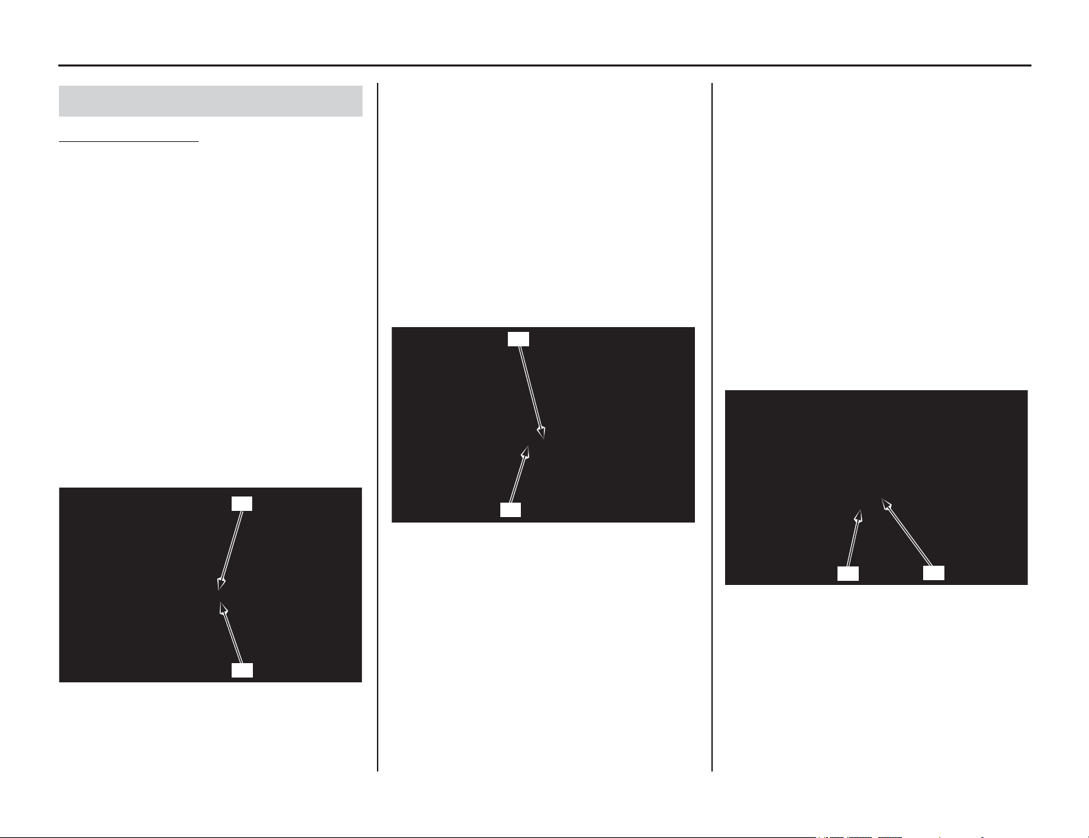
Rear Suspension Adjustments
(cont’d)
Adjustments 147
Compression Damping
Compression damping may be adjusted in two
stages with separate adjusters.
The high speed compression damping adjuster (1)
is effective when damping adjustment is desired
for high speed operation. The low speed
compression damping adjuster (2) should be used
when damping adjustment is desired at relatively
low speeds.
• When adjusting the compression damping
adjusters, make sure to use the proper size tool
to avoid damage.
• Both the high and low speed compression
damping can be increased by turning the
appropriate adjuster clockwise.
• Adjust the high speed compression damping
adjuster in 1/4 turn increments.
• Be sure the high speed compression adjuster is
firmly located in a detent, and not between
positions.
High Speed Damping:
The high speed damping can be adjusted by
turning the hexagonal portion of the compression
damping adjuster.
The high speed compression damping adjuster has
3 1/2 turns or more.
To adjust to the standard position:
1. Turn the adjuster clockwise (harder) until it
will no longer turn (lightly seats).
2. Turn the adjuster counterclockwise (softer) 3
1/4 turns. Further turn it by ± 1/4, align the
punch mark (3) on the adjuster and the punch
mark (4) on the adjuster body.
Low Speed Damping:
The low speed damping can be adjusted by turning
the center screw of the compression damping
adjuster.
The low speed compression damping adjuster has
13 clicks or more.
Turning the adjuster one full turn clockwise
advances the adjuster 4 clicks.
To adjust to the standard position:
1. Turn the adjuster clockwise (harder) until it
will no longer turn (lightly seat). Turn the
adjuster counterclockwise (softer) until it
clicks. This click is position 1.
2. Set the adjuster 11 clicks and adjust it until the
punch mark (5) on the adjuster and the punch
mark (4) on the adjuster body are aligned.
Rear Suspension Damping
(1) high speed compression damping adjuster
(2) low speed compression damping adjuster
(1)
(2)
(3) high speed compression damping adjuster punch
mark
(4) adjuster body punch mark
(3)
(4)
(4) adjuster body punch mark
(5) low speed compression damping adjuster punch
mark
(5)
(4)
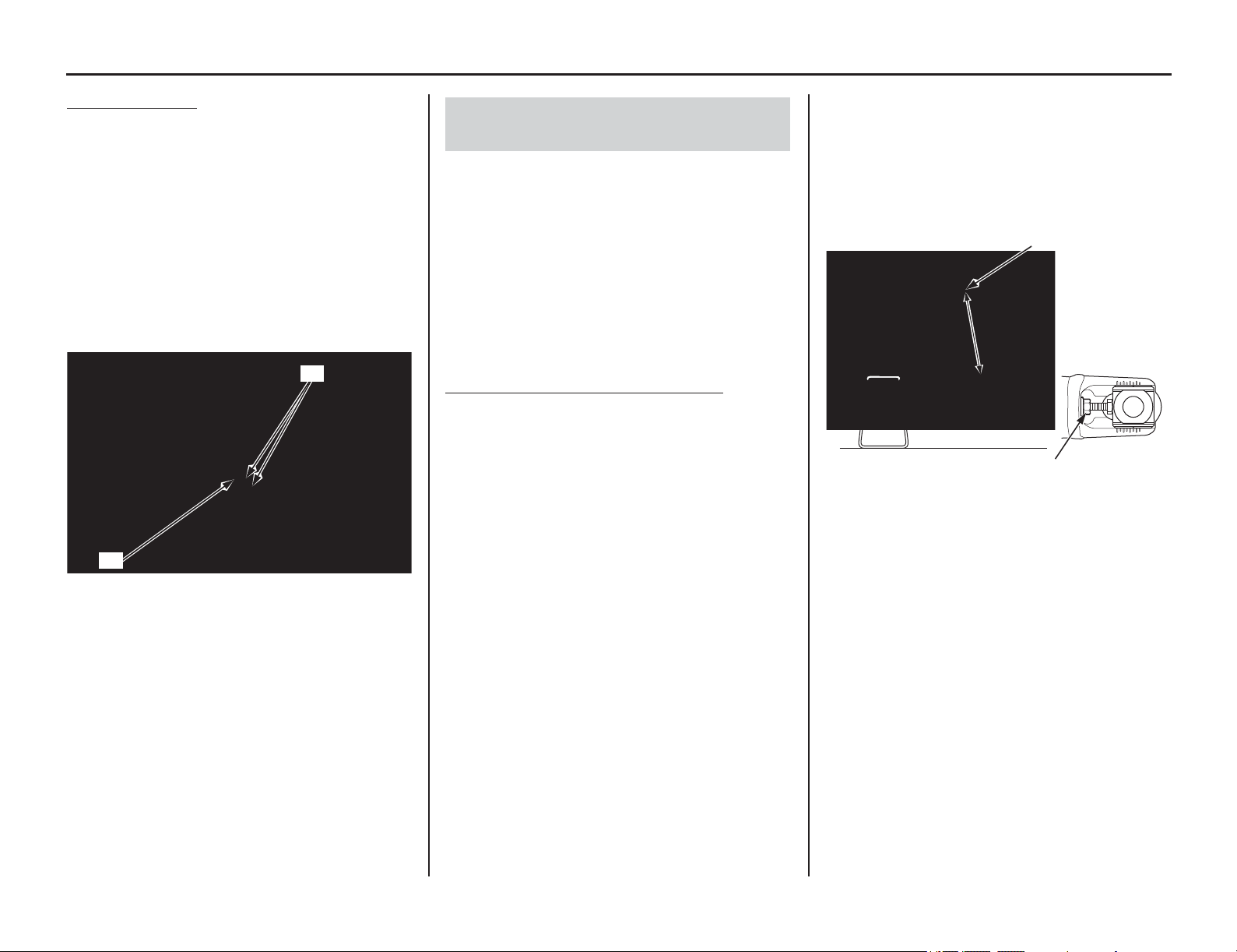
148 Adjustments
Rear Suspension Adjustments
Rebound Damping
The rebound damping adjuster (6) is located at the
lower end of the rear shock absorber.
It has 17 clicks or more. Turning the adjuster one
full turn changes the adjuster 8 clicks.
• When adjusting the rebound damping adjuster,
make sure to use the proper size tool to avoid
damage.
• Rebound damping can be increased by turning
the adjuster clockwise.
• Be sure that the rebound adjuster is firmly
located in a detent, and not between positions.
To adjust to the standard position:
1. Turn the adjuster clockwise (harder) until it
will no longer turn (lightly seat). Turn the
adjuster counterclockwise (softer) until it
clicks. This click is position 1.
2. Set the adjuster 7 to 10 clicks and adjust it until
the punch marks (7) on the adjuster and the rear
shock absorber are aligned.
Setting the proper race sag (ride height) is very
important for off-road use.
Race sag refers to the amount of rear wheel travel
used by your motorcycle at rest, ready to ride, with
you on the seat. As a general rule of thumb, the
race sag dimension should be about one-third of
the maximum travel.
On your motorcycle, ride height is changed by
adjusting the rear suspension spring pre-load.
Spring Pre-load & Race Sag Adjustment
The following adjustment procedure establishes
the correct starting point for any suspension tuning
— the proper rear suspension spring preload
adjustment for your specific needs.
Your motorcycle should be at normal racing
weight, including fuel, oil and coolant. You should
be wearing all your normal protective apparel. You
will need two helpers.
To calculate the proper adjustment, it is necessary
to measure between two fixed points — from the
center of the seat mounting bolt to the center of the
chain adjuster lock nut as illustrated here — for
two different situations:
unloaded: motorcycle on an optional workstand
with rear suspension fully extended, no rider.
loaded with rider: motorcycle on ground, with
rider.
1. Support your motorcycle on an optional
workstand with the rear wheel off the ground.
2. Measure the unloaded dimension.
3. Measure the loaded with rider dimension.
Remove the workstand. With two helpers
available, sit as far forward as possible on your
motorcycle’s seat, wearing your riding
apparel.
Ask one helper to steady your motorcycle
perfectly upright so you can put both feet on
the pegs.
Bounce your weight on the seat a couple of
times to help the suspension overcome any
situation and settle to a good reference point.
(6) rebound damping adjuster (7) punch marks
(6)
(7)
Rear Suspension Race Sag
(Off-Road Use Only)
UNLOADED
MEASUREMENT
(without rider)
EXAMPLE:
24.6 in (625 mm)
SEAT MOUNTING BOLT
CHAIN ADJUSTER LOCK NUT
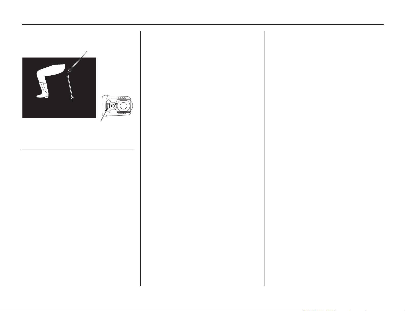
Adjustments 149
Rear Suspension Adjustments
Ask the other helper to measure the loaded
with rider dimension.
Example:
4. Calculate the race sag dimension.
To do this, subtract the loaded with rider
dimension (step 3) from the unloaded
dimension (step 2).
Standard Race Sag: 4.1 in (105 mm)
Adjust spring pre-load as necessary to obtain
the desired handling results.
Decreasing the race sag dimension (example:
3.7 in, 95 mm) improves turning ability for
tight terrain at the cost of slightly reduced
straight line stability.
Increasing the race sag dimension (example:
4.5 in, 115 mm) may improve stability on
faster terrain with less turns, but will reduce
turning performance slightly and may upset the
balance between the front and rear suspension,
producing a harsher ride. This will happen if
the adjustment shifts the effective wheel travel
toward the more progressive end of its range.
Unloaded = 24.6 in (625 mm)
– Loaded = 20.7 in (525 mm)
Race Sag = 3.9 in (100 mm)
LOADED
MEASUREMENT
(with rider)
EXAMPLE:
20.7 in (525 mm)
SEAT MOUNTING BOLT
CHAIN ADJUSTER LOCK NUT
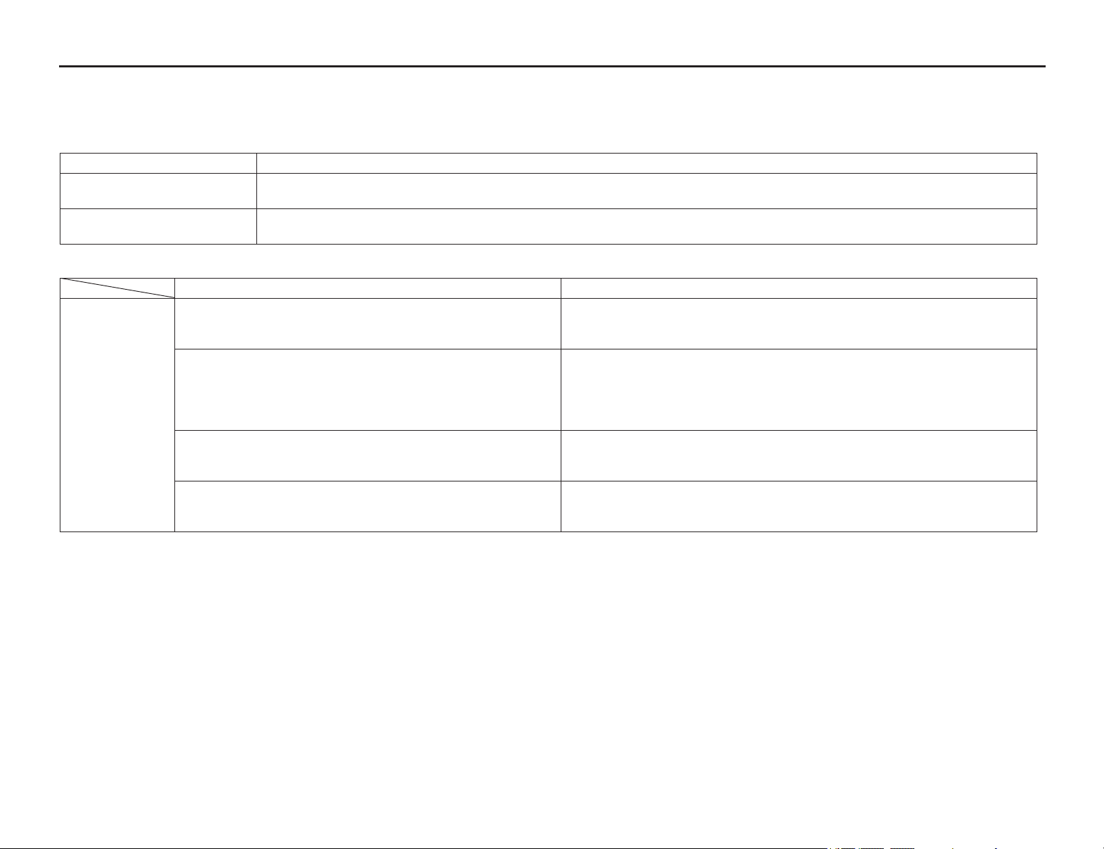
Suspension Adjustment Guidelines (Off-Road Use Only)
150 Adjustments
Follow the
procedures described below to accurately adjust your motorcycle, using the methods described on pages 144 – 148. Remember to make all adjustments
in one-click or 1/12 turn increments. Test ride after each adjustment.
Front Suspension Adjustment
Adjustments for Type of Track
Hard-surfaced track Begin with the standard setting. If the suspension is too stiff/soft, adjust according to the chart below.
Sand track Adjust to a stiffer position.
Example: – Turn the compression damping adjuster to a stiffer position.
Mud track Adjust to a stiffer position because mud build-up increases your motorcycle’s weight.
Example: – Turn the compression damping adjuster to a stiffer setting.
Adjustments for Too Soft/Stiff Damping
Symptom Action
Soft
suspension
Initial travel too soft:
• Steering is too quick.
• Front end darts while cornering or riding in a straight line.
– Test stiffer compression damping adjustments in one-click increments.
– Test stiffer rebound damping in one-click increments.
Middle travel too soft:
• Front end dives when cornering.
If suspension isn’t stiff in initial travel:
– Test stiffer compression damping adjustments in one-click increments.
If initial travel becomes stiff because of the above adjustment:
– Reduce the rebound damping in one-click increments.
– Test softer compression damping adjustments in one-click increments.
Final travel too soft:
• Bottoms on landings.
• Bottoms on large bumps, especially downhill bumps.
If initial and middle travel aren’t stiff:
– Test stiffer compression damping adjustments in one-click increments.
Entire travel too soft:
• Front end shakes.
• Fork bottoms over any type of terrain.
– Test stiffer compression damping adjustments in one-click increments.
– Increase rebound damping in one-click increments.
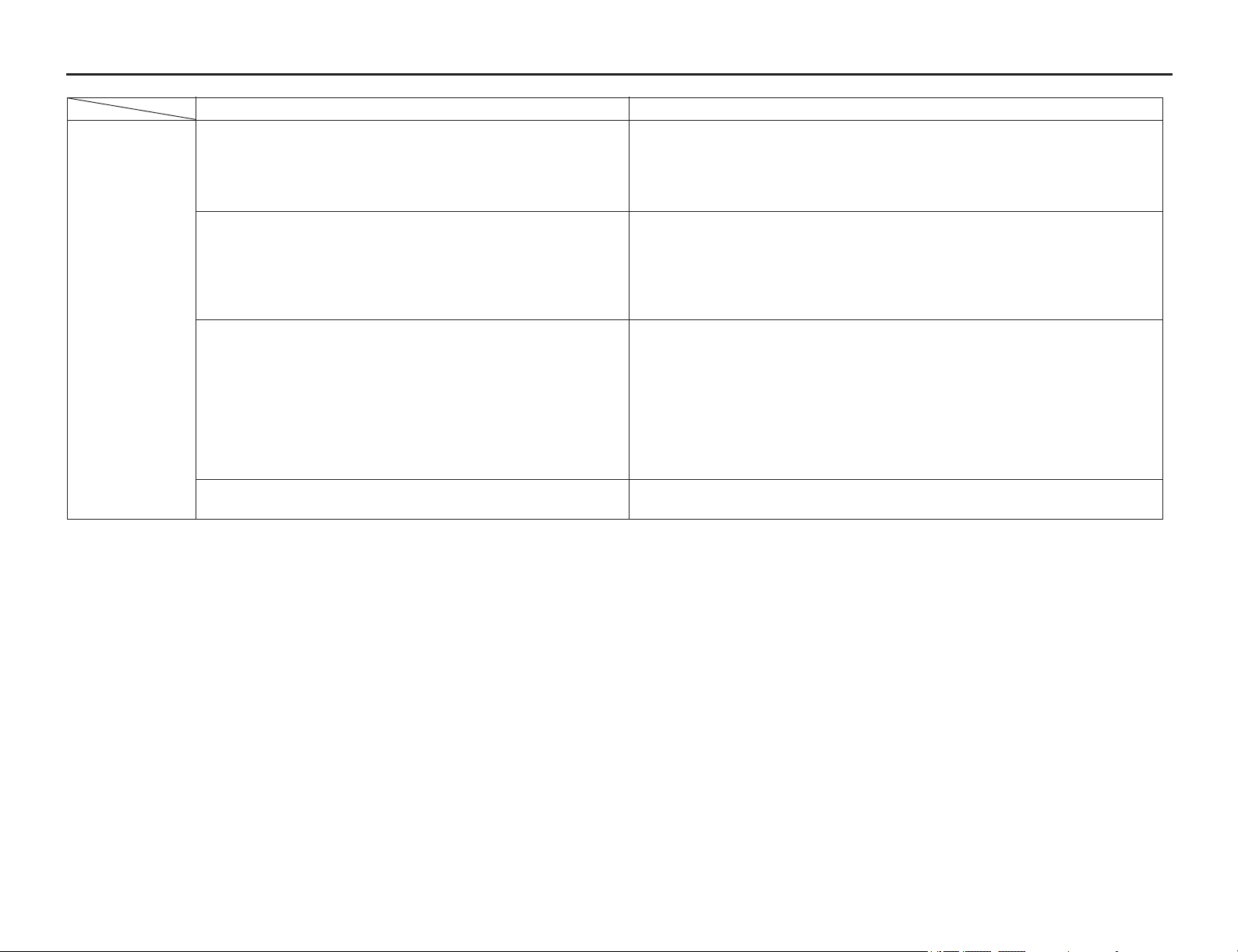
Suspension Adjustment Guidelines (Off-Road Use Only)
Adjustments 151
Symptom Action
Stiff
suspension
Initial travel too stiff:
• Stiff on small bumps while riding at full throttle in a straight line.
• Stiff on small cornering bumps.
• Front end wanders while riding at full throttle in a straight line.
– Test softer compression damping adjustments in one-click increments.
– Reduce the rebound damping adjustments in one-click increments.
– Check for dirt in the dust seals. Check the fork oil for any contamination.
If the front end dives while cornering after the above adjustment:
Reduce the rebound damping in one-click increments.
Middle travel too stiff:
• Stiff on bumps when cornering.
• Front end wanders when cornering.
• Stiff suspension on bumps, especially downhill bumps.
• While braking, front end dives during initial travel, then feels stiff.
If initial travel isn’t stiff:
– Test stiffer compression damping adjustments in one-click increments. (This
should produce smooth fork action from initial to middle travel.)
If initial and middle travel is stiff:
– Test softer compression damping adjustments in one-click increments.
– Reduce the rebound damping in one-click increments.
Final travel too stiff:
• Doesn’t bottom on landings, but feels stiff.
• Stiff on large bumps, especially downhill bumps.
• Stiff on large bumps when cornering.
If initial and middle travel aren’t stiff:
– Test stiffer compression damping adjustments in one-click increments. (This
should produce smooth fork action from initial to middle travel.)
If final travel is still stiff after the above adjustment, or
If initial and middle travel becomes stiff:
– Test softer compression damping adjustments in one-click increments.
If the entire travel feels stiff after the above adjustment:
– Test softer compression damping adjustments in one-click increments until the
desired initial travel compression damping is obtained.
Entire travel too stiff:
• Stiff suspension on any type of terrain.
– Test softer compression damping adjustments in one-click increments.
– Reduce the rebound damping in one-click increments.
Suspension Adjustment Guidelines (Off-Road Use Only)
152 Adjustments
Rear Suspension Adjustment
Adjustments for Type of Track
Hard-surfaced track Begin with the standard settings. If the suspension is too stiff/soft, adjust according to the chart below.
Sand track Lower the rear end (to improve front wheel stability) by increasing Race Sag (reduce spring pre-load).
Example: – Turn the compression damping adjuster and, especially, rebound damping adjuster to a stiffer setting.
– Increase standard Race Sag (+0.2 to 0.4 in/5 to 10 mm).
Mud track Adjust to a stiffer position because mud build-up increases your CRF’s weight.
Example: – Adjust the compression and rebound damping adjusters to stiffer settings.
– Reduce standard Race Sag (–0.2 to –0.4 in/–5 to –10 mm).
Symptoms and Adjustment
• Always begin with the standard settings.
• Turn the low speed compression and rebound adjusters in one-click increments, and the high speed compression adjuster in 1/12 turn increments at a time. Adjusting two or
more clicks or turns at a time may cause you to pass over the best adjustment. Test ride after each adjustment.
• If, after setting, the suspension feels unusual, find the corresponding symptom in the table and test stiffer or softer compression and/or rebound damping adjustments until the
correct settings are obtained as described.
Symptom Action
Stiff suspension Suspension feels stiff on small bumps 1. Test softer low speed compression adjustment.
2. If it still feels stiff, further test softer low and high speed compression adjustments simultaneously.
Suspension feels stiff on large bumps 1. Test softer high speed compression adjustment.
2. If it still feels stiff, further test softer low and high speed compression adjustments simultaneously.
Entire travel too stiff 1. Test softer high and low speed compression adjustments and rebound adjustment simultaneously.
Soft suspension Entire travel too soft 1. Test stiffer high and low speed compression adjustments simultaneously.
Rear end sways 1. Test stiffer high and low speed compression adjustments and rebound adjustment to stiffer settings
simultaneously.
Suspension
bottoms
Suspension bottoms at landing after
jumping
1. Test stiffer high speed compression adjustment.
2. If it still bottoms, test stiffer high and low speed compression adjustments.
Suspension bottoms after landing 1. Test stiffer low speed compression adjustment.
2. If it still bottoms, test stiffer high and low speed compression adjustments.
Suspension bottoms after end of
continuous bumps
1. Test softer rebound damping adjustment.
2. If it still bottoms, test stiffer high and low speed compression adjustments and softer rebound damping
adjustment.
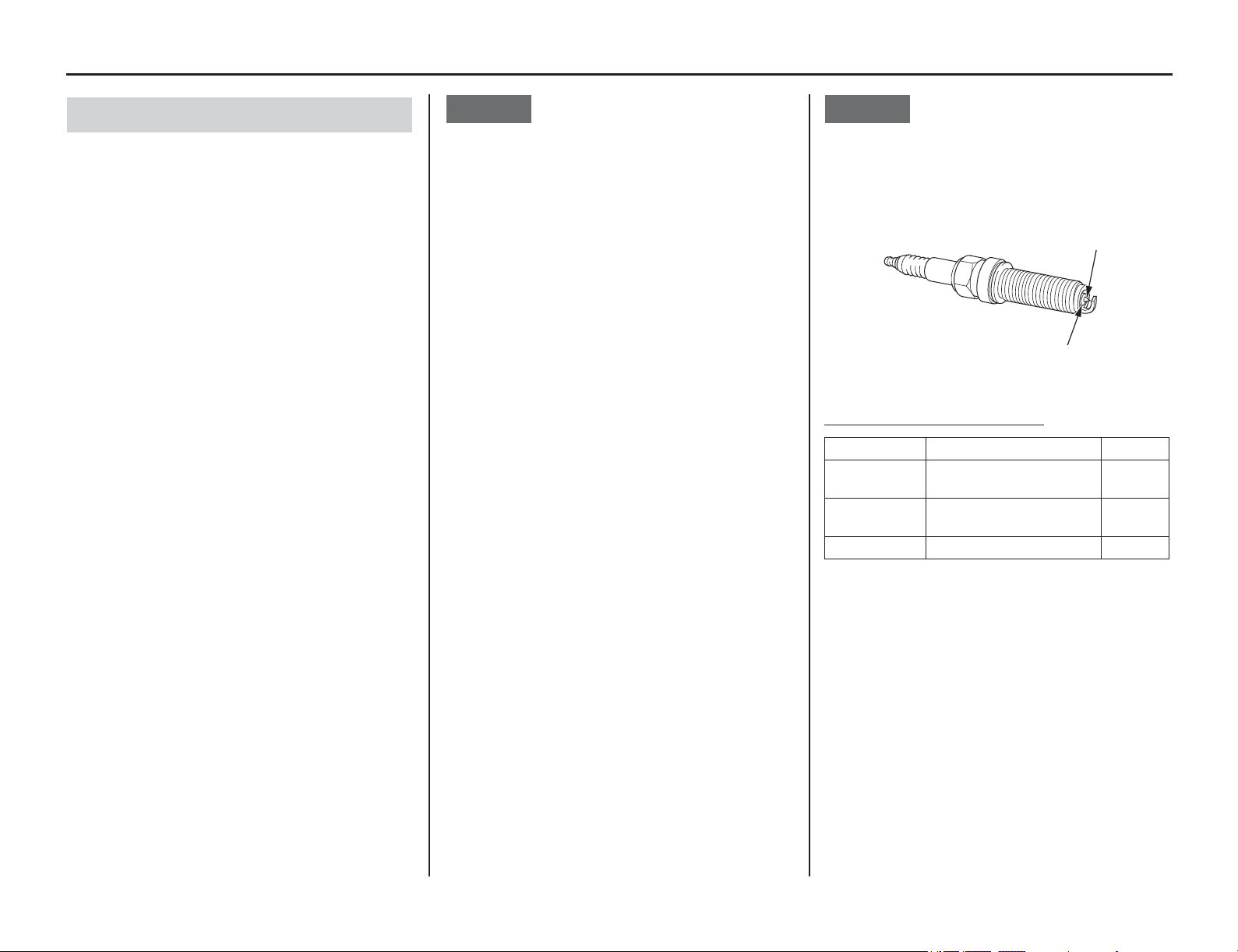
Tuning Tips
Adjustments 153
Refer to Spark Plug on page 86.
The following procedure is recommended.
You may not get an accurate reading if you simply
turn off the engine and pull the plug for inspection.
Use a new spark plug. Inspect the plug before
installing it.
NOTICE
Using spark plugs with an improper heat range or
incorrect reach can cause engine damage.
Ride for 10 – 15 minutes before taking a plug
reading. A new plug will not color immediately.
Before removing the spark plug, clean the spark
plug area thoroughly to prevent dirt from entering
the cylinder.
To obtain an accurate reading of a new spark plug:
1. Accelerate at full throttle on a straight.
2. Depress and hold the engine stop button and
pull the clutch lever in.
3. Coast to a stop.
4. Remove the spark plug.
5. Use a magnifying glass to inspect the spark
plug. The porcelain insulator (1) around the
center electrode (2) should appear clean and
colorless with a gray ring around the center
electrode where it exits the porcelain.
Light gray or white color streaks the porcelain
insulator and center electrode indicate lean air-
fuel mixture. Wet or black sooty streaks on the
porcelain indicate rich air-fuel mixture.
NOTICE
An improperly tightened spark plug can damage
the engine. If a plug is too loose, the piston may be
damaged. If a plug is too tight, the threads may be
damaged.
Spark Plug Coloring Guidelines
Remember that in addition to improper air-fuel
mixture:
• A lean condition can be caused by air leaks in
the inlet tract or exhaust system, the passage of
too much air because of the use of the wrong
air cleaner, or use of a less-restrictive
aftermarket exhaust system.
• A rich condition can be caused by a plugged or
dirty air cleaner, use of a more-restrictive
aftermarket exhaust system, or excessive oil on
the air cleaner.
Excessive smoking will occur.
Spark Plug Reading (Off-Road Use Only)
(1) porcelain insulator (2) center electrode
Condition Spark Plug Appearance Mixture
Normal Dark brown to light tan
color with dry electrode
correct
Overheating
(Lean)
Light gray or white color lean
Wet (Rich) Wet or sooty rich
(2)
(1)
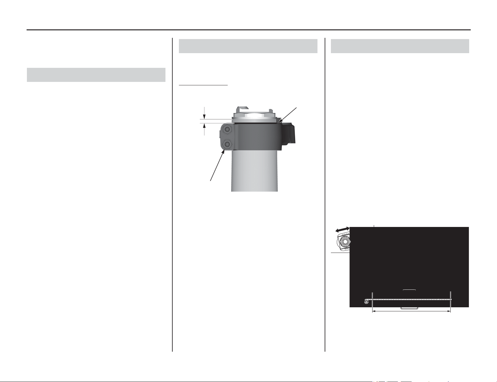
Chassis Adjustments
154 Adjustments
Chassis Adjustments
The following suggestions may improve a specific
concern. Subtle changes in overall handling may
also be noted.
If you have a problem with rear wheel traction,
raise the rear end of your motorcycle by increasing
the rear suspension spring pre-load. Instead of
running 3.9 in (100 mm) of sag, you can run 3.5 in
(90 mm) so the rear of the motorcycle will sit a
little higher. This should produce more traction
because of the change to the swingarm and
location of your motorcycle’s center of gravity.
If you have a problem with the steering head
shaking when you use the front brake hard or if
your motorcycle wants to turn too quickly, lower
the rear of the motorcycle by reducing the rear
suspension spring pre-load. This will increase fork
rake and trail and should improve stability in a
straight line. The effective suspension travel will
be transferred toward the firmer end of wheel
travel.
Keep the race sag adjustment (page 148) in the 3.7
– 4.5 in (95 – 115 mm) range.
The position of the fork in the clamp is not
adjustable.
Standard Position
The groove (1) in the outer tube is aligned with the
top surface of the upper fork bridge (2).
Adjusting your motorcycle’s wheelbase can offer
subtle changes in overall handling. You may adjust
wheelbase by adding or removing links on the
drive chain. If you change the wheelbase, be sure
to recheck race sag and adjust, if necessary.
In the past, a general rule was lengthen the
wheelbase to add straight line stability, shorten the
wheelbase to improve turning. However, we
suggest you do not lengthen the wheelbase of your
motorcycle unless you are racing on a track with
more fast sections than normal.
As a general recommendation, keep the wheelbase
as short as possible. This positions the wheels
closer together, improves turning response,
increases weighting (traction) on the rear wheel,
and lightens weighting on the front wheel.
With your motorcycle, you will probably find that
the standard setting or a shorter wheelbase will
offer more overall benefits.
Rear End (Off-Road Use Only)
Fork Height/Angle (Off-Road Use Only)
(1) groove
(2) upper fork bridge
(2)
(1)
Wheelbase (Off-Road Use Only)

Tire Selection for Track Conditions (Off-Road Use Only)
Adjustments 155
Choosing the correct tire tread pattern and rubber
compound can
affect your placing in off-road use.
The tires on your motorcycle offer a “happy
medium” for the variety of soil conditions the
majority of riders are likely to encounter.
Experienced competitors often switch to tires
developed for specific terrain conditions. If you do
switch, stay with the factory recommended sizes.
Other tires may affect handling or acceleration.
Be aware that tire sizes (width and aspect ratio) do
vary from manufacturer to manufacturer or even
among tires made by the same manufacturer.
Variations in tires, especially the sidewall profile,
can change the attitude of your motorcycle and its
handling. Tire variations that raise or lower the
rear of your motorcycle have a more significant
effect on handling than variations in front tires
which, generally, don’t vary as much.
Often, you can see or feel the change in tire size.
Another way to check is to measure the rolling
circumference of the old and new tires. A higher
profile tire will have a larger rolling
circumference.
If you do switch to tires designed for special terrain
use, remember they will be less acceptable in other
circumstances. For example, an aggressive mud
tire will give excellent grip on wet, loamy terrain,
but less impressive grip on a hard surface.
If you choose a tire with a sticky compound for
added traction, remember that it may transfer
additional loads to the transmission because it
grips so well, especially when riding in situations
that normally place unusual demands on the
transmission.
Complete consumer information can be obtained
from the various tire manufacturer representatives
and dealers.
Some general recommendations for specific
terrain follow:
Hard, Slick Soil
Use tires with many relatively short knobs that are
close together in order to obtain the largest
possible contact patch on the surface. The rubber
compound needs to be softer for hard ground in
order to hook up, but not so soft that the knobs roll
over easily and affect holding a straight line.
These tires tend to wear more quickly than
standard tires because of the combination of soft
rubber and hard terrain.
Muddy Soil
Use a more open tread pattern to avoid clogging.
For these conditions, the relatively long knobs will
probably be made from a harder rubber compound
to reduce any tendency to bend back under
acceleration or wear quickly.
Loose, Sandy Soil
Use a tire that is similar in construction to those
needed for tacky soil and mud, but with a few more
knobs.
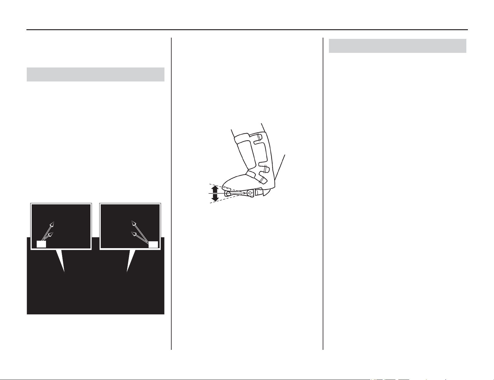
Personal Fit Adjustments
156 Adjustments
Personal Fit Adjustments
The following suggestions may make your ride
both more comfortable and more responsive to
your control input.
• Position the control levers so that you can use
them comfortably when seated and standing.
• Adjust the mounting bolt (1) torque of the
clutch and front brake lever assemblies so that
they can rotate on the handlebar in a fall. If an
assembly does not rotate, it may bend or break
a control lever. Make sure that the bolts are
torqued securely enough to prevent slippage
during normal operation.
Apply Pro Honda Hondalock or an equivalent to
the threads of these bolts prior to adjustment to
help ensure the correct torque is retained.
Tighten the top bolts first.
As an alternative, consider wrapping the handlebar
area under the control assemblies with Teflon tape.
Then tighten the assemblies to their normal torque.
Upon impact, the fully-tightened assemblies
should rotate on the Teflon tape.
• Position the shift lever and rear brake pedal so
they are close to your boot for rapid access, but
not so close that either is depressed when
sitting or standing comfortably on your
motorcycle.
• Position the handlebar so that both gripping the
bar and operating the controls are comfortable
while both seated and standing, while riding
straight ahead and turning.
Tighten the forward handlebar upper holder
bolts first.
• The handlebar position may be moved
backward 0.2 in (6 mm) (by rotating the lower
holders 180 degrees).
Refer to an official Honda Service Manual for
installation instructions. Be sure to check
control cable and wiring harness routing after
the adjustment.
Control Positioning (Off-Road Use Only)
(1) control lever mounting bolts
(1)
(1)
Handlebar Position (Off-Road Use Only)

Tips
Tips 157
Here’s h
elpful advice on how to transport and store
your motorcycle, as well as three troubleshooting
flow charts.
Transporting Your Motorcycle...................... 158
Storing Your Honda ...................................... 159
Preparation for Storage.............................. 159
Removal from Storage .............................. 159
You & the Environment ................................ 160
Troubleshooting............................................. 161
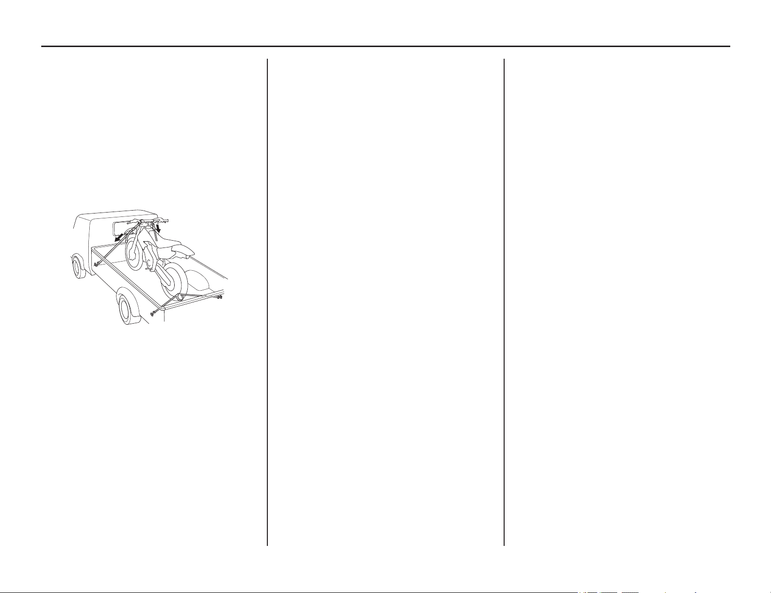
Transporting Your Motorcycle
158 Tips
Transporting Your Motorcycle
If you use a truck or motorcycle trailer to transport
your motorcycle, we recommend that you follow
these guidelines:
• Use a loading ramp.
• Relieve the fuel pressure (page 48) and drain
the fuel from the fuel tank into an approved
gasoline container.
• Secure the motorcycle in an upright position,
using motorcycle tie-down straps. Avoid using
rope, which can loosen and allow the
motorcycle to fall over.
To secure your motorcycle, brace the front wheel
against the front of the truck bed or trailer rail.
Attach the lower ends of two straps to the tie-down
hooks on truck bed or trailer rail. Attach the upper
ends of the straps to the handlebar (one on the right
side, the other on the left), close to the fork.
Check that the tie-down straps do not contact any
control cables or electrical wiring.
Tighten both straps until the front suspension is
compressed about half-way. Too much pressure is
unnecessary and could damage the fork seals.
Use another tie-down strap to keep the rear of the
motorcycle from moving.
We recommend that you do not transport your
motorcycle on its side. This can damage the
motorcycle, and leaking gasoline could be a
hazard.
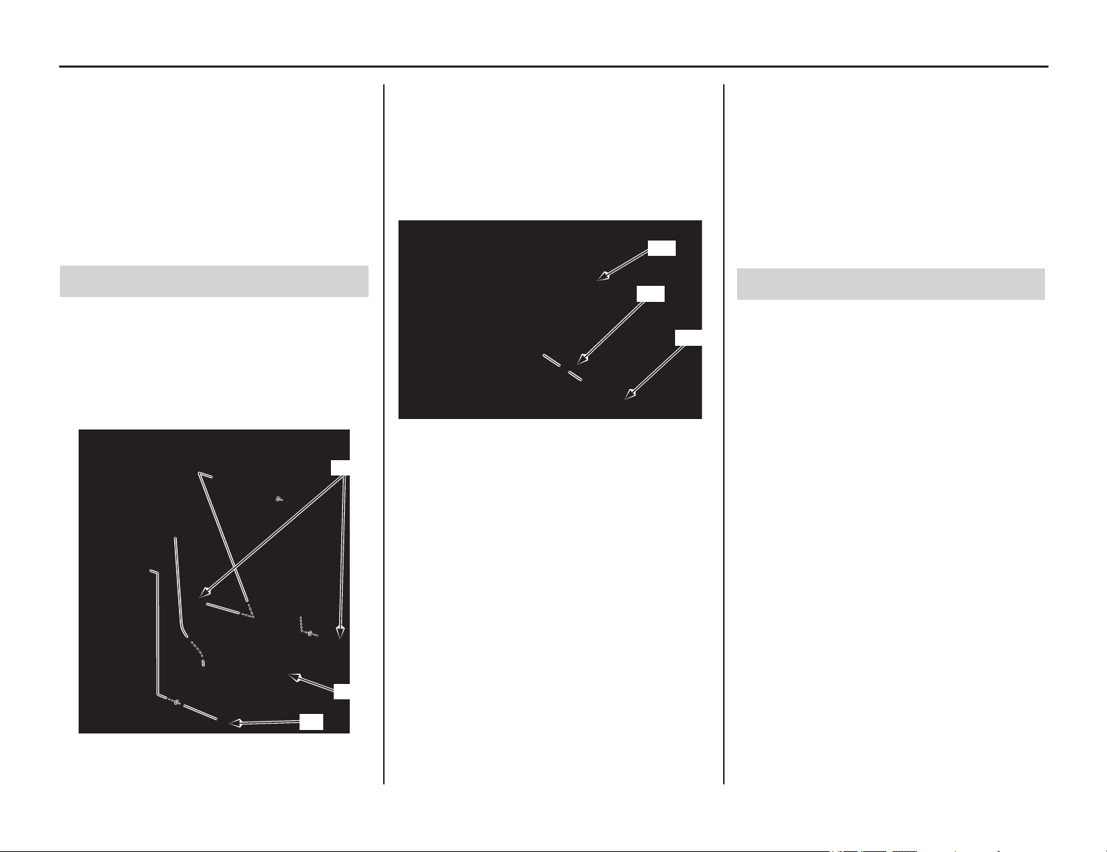
Storing Your Honda
Tips 159
If you
won’t be riding for an extended period, such
as during the winter, thoroughly inspect your
motorcycle and correct any problem before storing
it. That way, needed repairs won’t be forgotten and
it will be easier to get your motorcycle running
again.
To reduce or prevent deterioration that can occur
during storage, also follow the following
procedures.
1. Completely clean all parts of your motorcycle.
If your motorcycle has been exposed to sea air
or salt water, wash it down with fresh water
and wipe dry.
2. Change the engine oil and filter (page 70).
3. Remove the engine guard A bolts/washers (1), B
bolt/washer (2) and engine guard (3).
4. Remove the radiator cap and coolant drain bolt
(4) and sealing washer (5) at the water pump
cover (6) to drain coolant.
After the coolant has been completely drained,
reinstall the drain bolt with a new sealing
washer and radiator cap.
Tighten the drain bolt to the specified torque:
7 lbf·ft (10 N·m, 1.0 kgf·m)
5. Install the engine guard (3), then tighten the
engine guard A bolts/washers (1), B bolt/
washer (2) to the specified torque:
7 lbf·ft (10 N·m, 1.0 kgf·m)
6. Lubricate the drive chain.
7. Relieve the fuel pressure (page 48) and drain
the fuel from the fuel tank into an approved
gasoline container.
8. Remove the battery.
Store in an area protected from freezing
temperatures and direct sunlight. Slow charge
the battery (page 139) once a month.
9. Inflate the tires to their recommended
pressures.
10. Place your motorcycle on an optional
workstand or equivalent to raise both tires off
the ground.
11. Stuff a rag into the muffler outlet. Then tie a
plastic bag over the end of the muffler to
prevent moisture from entering.
12. Store your motorcycle in an unheated area, free
of dampness, away from sunlight, with a
minimum of daily temperature variation.
13. Cover your motorcycle with a porous material.
Avoid using plastic or similar non-breathing,
coated materials that restrict air flow and allow
heat and moisture to accumulate.
1. Uncover and clean your motorcycle.
Change the engine oil if more than 4 months
have passed since the start of storage.
2. Uncover the end of the muffler and remove the
rag from the muffler outlet.
3. Fill the fuel tank with the recommended fuel
(page 60).
4. Charge the battery (page 139) as required.
Install the battery.
5. Pour a fresh recommended coolant mixture
slowly into the radiator filler hole up to the
filler neck (page 72).
Capacity:
1.31 US qt (1.24 ℓ) after disassembly
1.20 US qt (1.14 ℓ) after draining
Remove the radiator reserve tank cap and fill
the reserve tank to the upper level line.
Bleed air from the system (page 73).
6. Increase the fuel pressure (page 68).
7. Perform all maintenance checks (page 19).
Preparation for Storage
(1) engine guard A bolts/washers
(2) engine guard B bolt/washer
(3) engine guard
(1)
(2)
(3)
(4) coolant drain bolt
(5) sealing washer (new)
(6) water pump cover
(6)
(5)
(4)
Removal from Storage
You & the Environment
160 Tips
You & the Environment
Owning and riding a motorcycle can be enjoyable,
but you must do your part to protect nature. When
you show respect for the land, wildlife, and other
people, you also help preserve the sport of off-road
riding.
Following are tips on how you can be an
environmentally responsible motorcycle owner.
• Choose Sensible Cleaners. Use a
biodegradable detergent when you wash your
motorcycle. Avoid aerosol spray cleaners that
contain chlorofluorocarbons (CFCs) which
damage the atmosphere’s protective ozone layer.
Don’t throw cleaning solvents away; see the
following guidelines for proper disposal.
• Recycle Wastes. It’s illegal and thoughtless to
put used engine oil in the trash, down a drain, or
on the ground. Used oil, gasoline, coolant, and
cleaning solvents contain poisons that can hurt
refuse workers and contaminate our drinking
water, lakes, rivers, and oceans.
Before changing your oil, make sure you have
the proper containers. Put oil and other toxic
wastes in separate sealed containers and take
them to a recycling center. Call your local or
state office of public works or environmental
services to find a recycling center in your area
and get instructions on how to dispose of non
recyclable wastes.
NOTICE
Improper disposal of drained fluids is harmful to
the environment.
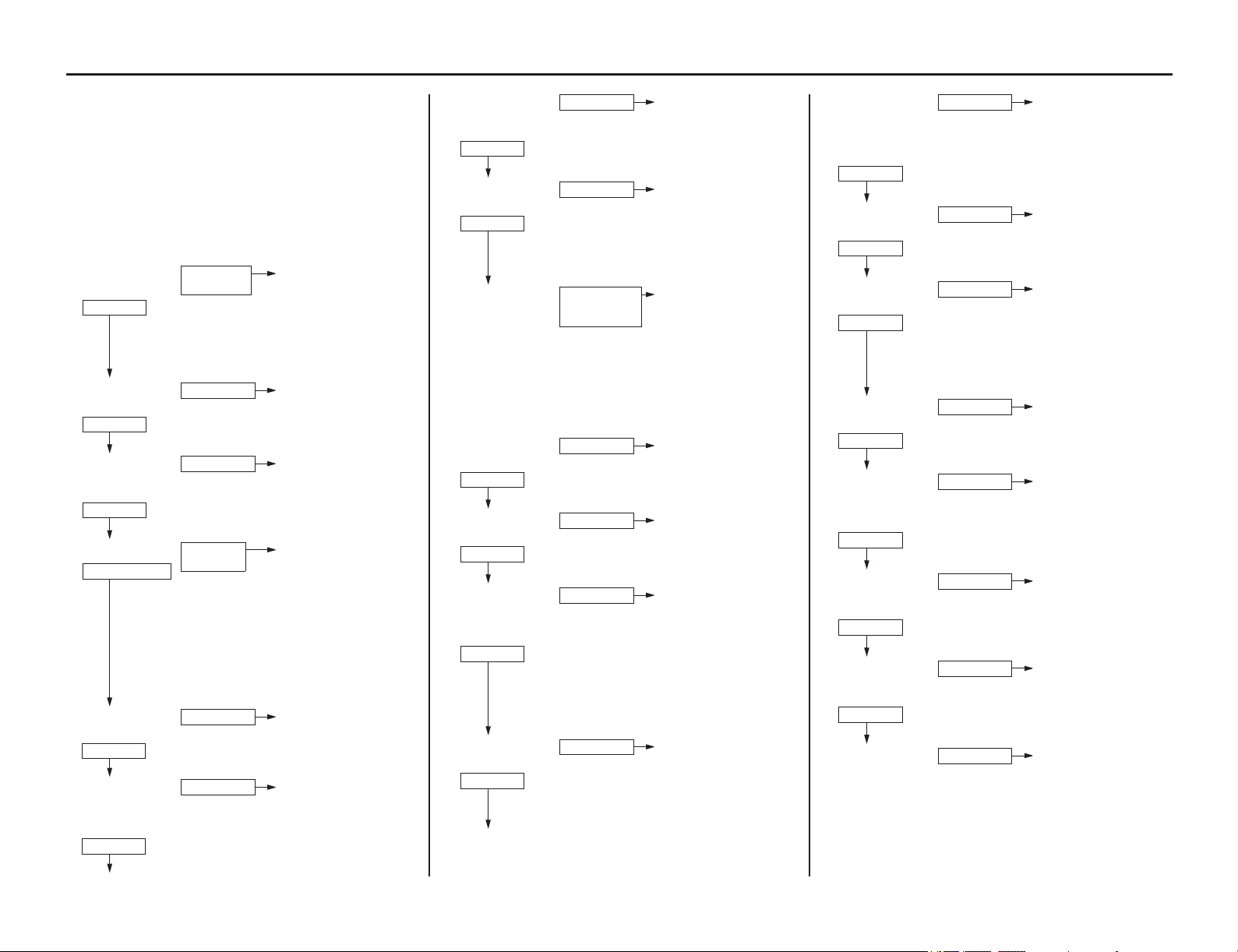
Troubleshooting
(cont’d)
Tips 161
The items that are
serviceable using this Manual
are followed by the page number reference in
parenthesis. The items that require use of an
official Honda Service Manual are followed by an
asterisk (*).
ENGINE DOES NOT START OR IS HARD TO START
Operate the start button with the throttle grip in
fully closed position (page 25).
CHECK POSSIBLE CAUSES
1. Check the starter
motor*
• Loose or disconnected
battery terminals (P.139)
• Blown main fuse (P.172)
• Weak battery (P.139, 175)
• Faulty starter relay switch
or starter motor*
• Faulty start button*
• Faulty clutch switch
• Faulty CKP sensor*
2. Check the starter/
ignition relay*
• Faulty starter/ignition
relay
3. Check the spark
plug condition
(P.86)
• Incorrect spark plug heat
range
• Incorrect spark plug gap
• Dirty air cleaner element
4. Try spark test* • Faulty spark plug (P.86)
• Fouled spark plug (P.86)
• Faulty ECM*
• Broken or shorted spark
plug wire
• Faulty alternator*
• Faulty ignition coil*
• Faulty engine stop
button*
• Loose or disconnected
ignition system wires
• Faulty CKP sensor*
• Faulty regulator/rectifier*
5. Check the PGM-FI
system (P.9)
• Faulty PGM-FI system
6. Check the fuel
pump operation
and inspect the fuel
flow*
• Faulty fuel pump*
• Clogged fuel pump filter
TURN
DOES NOT
TURN
CORRECT
INCORRECT
CORRECT
INCORRECT
GOOD SPARK
WEAK OR
NO SPARK
CORRECT
INCORRECT
CORRECT
INCORRECT
7. Check the fuel
injector operating
sound
• Faulty PGM-FI system
• Faulty fuel injector
8. Test cylinder
compression*
• Valve clearance too small
• Valve stuck open
• Worn cylinder and piston
ring*
• Damaged cylinder head
gasket
• Improper valve timing*
• Seized valve
9. Start by following
normal starting
procedure
• Insulator leaking
• Improper ignition timing
(Faulty ECM or CKP
sensor)*
• Fast idle knob stuck open
or damaged
• Fuel contaminated
ENGINE LACKS POWER
CHECK POSSIBLE CAUSES
1. Check the wheel
spin smoothness
• Brake dragging
• Worn or damaged wheel
bearings
• Bent axle shaft
• Drive chain too tight
2. Check the tire
pressure (P.127)
• Faulty valve core
• Punctured tire
3. Check the engine
speed change
accordingly when
clutch is engaged*
• Clutch slipping
• Improperly adjusted
clutch lever freeplay
(P.81)
• Worn clutch discs/plates
(P.84)
• Warped clutch discs/
plates (P.84)
• Weak clutch springs*
• Sticking clutch lifter
• Additive in engine oil
4. Check the engine
speed increase
• Dirty air cleaner element
• Clogged muffler
• Fast idle knob stuck open
or damaged
• Restricted fuel fill cap
breather tube
• Restricted fuel flow
CORRECT
INCORRECT
CORRECT
LOW
ENGINE
STARTS BUT
SOON STOPS
CORRECT
INCORRECT
CORRECT
INCORRECT
GOOD
NO GOOD
GOOD
NO GOOD
5. Check the engine
knocking when
accelerate or run
the engine at high
speed
• Worn piston and cylinder*
• Use of poor quality fuel
• Excessive carbon build-
up in combustion
chamber
• Ignition timing too
advance (Faulty ECM)*
• Lean fuel mixture
6. Check the ignition
timing*
• Faulty ECM*
• Faulty CKP sensor*
7. Test cylinder
compression*
• Valve clearance too small
• Valve stuck open
• Worn cylinder and piston
ring*
• Damaged cylinder head
gasket
• Improper valve timing*
• Faulty decompressor
system*
8. Check the PGM-FI
system (P.9)
• Faulty PGM-FI system
9. Check the fuel
pump operation
and inspect the fuel
flow*
• Faulty fuel pump unit*
• Clogged fuel pump filter
10.Check the spark
plug condition
(P.86)
• Incorrect spark plug
• Incorrect spark plug gap
• Dirty air cleaner element
11.Check the engine
oil level and
condition (P.70)
• Engine oil level too high
• Engine oil level too low
• Contaminated engine oil
12.Remove the
cylinder head cover
and inspect
lubrication
• Faulty oil pump*
• Faulty pressure relief
valve*
• Clogged oil passage*
• Clogged oil strainer
screen*
NO
YES
CORRECT
INCORRECT
CORRECT
LOW
CORRECT
INCORRECT
CORRECT
INCORRECT
CORRECT
INCORRECT
CORRECT
INCORRECT
INCORRECT
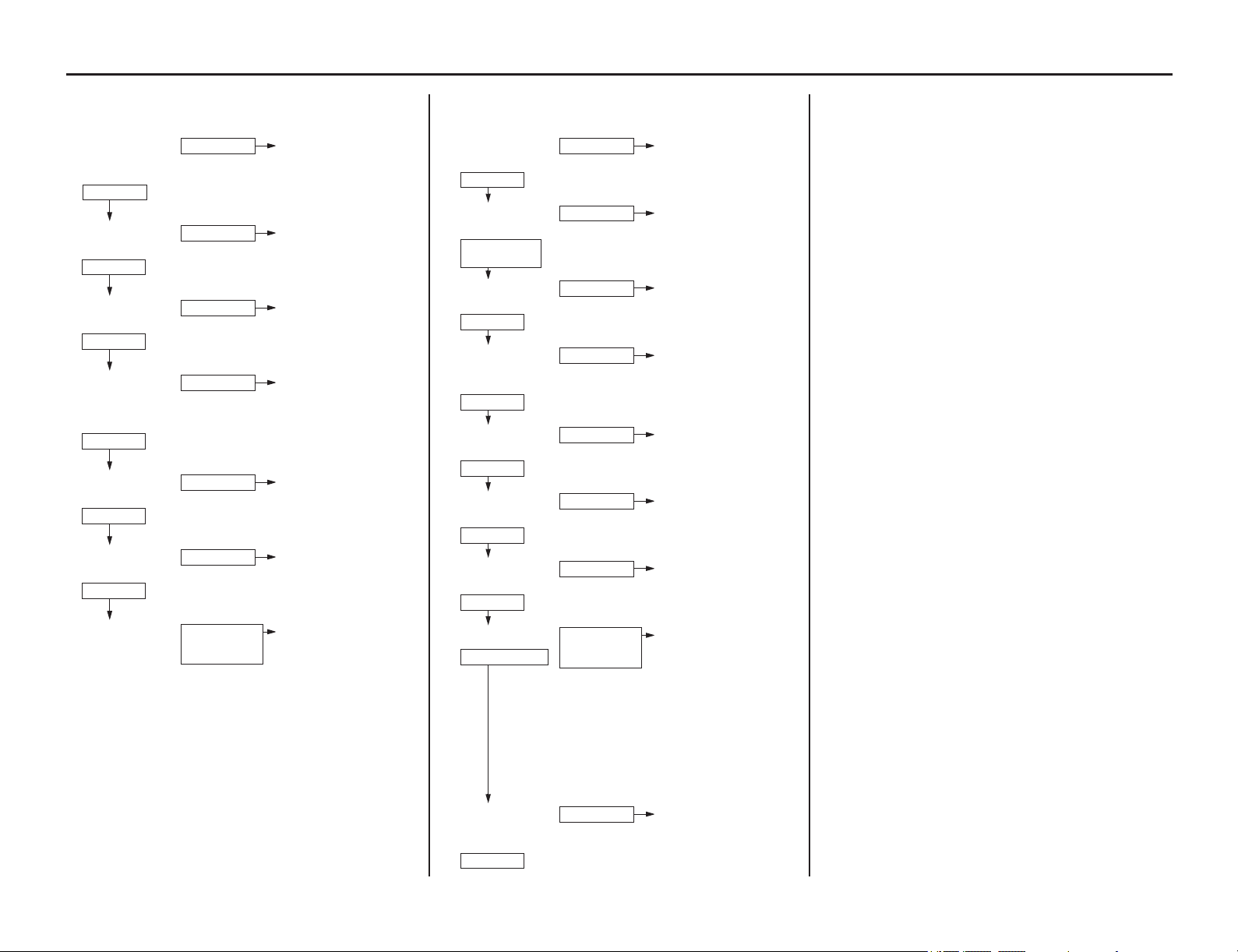
162 Tips
Troubleshooting
POOR HANDLING
Steering is heavy
• Steering stem adjusting nut too tight*
• Damaged steering head bearings
Either wheel is wobbling
• Excessive wheel bearing play
•Bent rim
• Improperly installed wheel hub
• Excessively worn swingarm pivot bearings
• Bent frame
The motorcycle pulls to one side
• Front and rear wheels not aligned
• Bent fork
• Bent swingarm
• Bent axle shaft
• Bent frame
POOR PERFORMANCE AT LOW AND IDLE SPEED
CHECK POSSIBLE CAUSES
1. Check the spark
plug condition
(P.86)
• Incorrect spark plug heat
range
• Incorrect spark plug gap
• Plug not serviced
frequently enough
2. Check the ignition
timing*
• Faulty ECM*
• Faulty CKP sensor*
3. Check the PGM-FI
system (P.9)
• Faulty PGM-FI system
4. Check the fuel
pump operation
and inspect the fuel
flow*
• Faulty fuel pump unit*
• Clogged fuel pump filter
5. Check the insulator
for leaks
• Loose insulator
• Damaged insulator
6. Check the valve
clearance (P.87)
• Faulty valve clearance
• Faulty valve*
• Faulty valve seat*
• Faulty camshaft*
7. Try spark test* • Faulty, carbon or wet
fouled spark plug (P.86)
• Faulty ECM*
• Faulty alternator*
• Faulty ignition coil*
• Broken or shorted spark
plug wire.
• Faulty CKP sensor*
• Loose or disconnected
ignition system wires
• Faulty engine stop
button*
• Faulty regulator/rectifier*
CORRECT
INCORRECT
CORRECT
INCORRECT
CORRECT
INCORRECT
CORRECT
INCORRECT
CORRECT
INCORRECT
CORRECT
INCORRECT
WEAK OR
INTERMITTENT
SPARK
POOR PERFORMANCE AT HIGH SPEED
CHECK POSSIBLE CAUSES
1. Check the ignition
timing*
• Faulty ECM*
• Faulty CKP sensor*
2. Check the air
cleaner (P.75)
• Not cleaned frequently
enough
3. Check the PGM-FI
system (P.9)
• Faulty PGM-FI system
4. Check the fuel pump
operation and
inspect the fuel flow*
• Faulty fuel pump unit*
• Clogged fuel pump filter
5. Check the valve
timing
• Camshaft not installed
properly (P.92)
6. Check the valve
clearance (P.87)
• Faulty valve clearance
• Faulty valve*
• Faulty valve seat*
• Faulty camshaft*
7. Check the valve
springs*
• Faulty valve springs*
8. Try spark test* • Faulty, carbon or wet
fouled spark plug (P.86)
• Faulty ECM*
• Faulty alternator*
• Faulty ignition coil*
• Broken or shorted spark
plug wire.
• Faulty CKP sensor*
• Loose or disconnected
ignition system wires
• Faulty engine stop
button*
• Faulty regulator/rectifier*
9. Remove and
inspect the cam
lobe height*
• Faulty camshaft*
CORRECT
INCORRECT
AIR CLEANER
NOT DIRTY
DIRTY
CORRECT
INCORRECT
CORRECT
INCORRECT
CORRECT
INCORRECT
CORRECT
INCORRECT
GOOD
WEAR
GOOD SPARK
WEAK OR
INTERMITTENT
SPARK
CORRECT
WORN

Taking Care of the Unexpected
Taking Care of the Unexpected 163
This s
ection discusses the more common problems
that can occur with your motorcycle while you’re
riding. It tells you how to evaluate each problem
and what actions you can take to try to resume
riding. If the problem cannot be safely solved, this
section also gives instructions on the proper way to
have your motorcycle transported.
For information about transporting your
motorcycle, see page 158.
General Guidelines ....................................164
If Your Engine Quits or Won’t Start..............165
If You Have a Flat Tire..................................167
Should You Repair or
Replace a Tire or Tube?.............................167
Emergency Front Wheel Removal/
Installation .................................................167
Emergency Rear Wheel Removal/
Installation .................................................169
If the High Coolant Temperature
Indicator Lights..............................................170
If You Have a Burned-out Light Bulb ...........171
Burned-out Light Bulb...............................171
If a Fuse Blows ..............................................172
If You Crash...................................................173
If You Lose Your Key ...................................174
If Your Battery Is Low (or Dead) ..................175

Taking Care of the Unexpected
164 Taking Care of the Unexpected
Taking Care of the Unexpected
Keeping your motorcycle well-maintained is the
best way to reduce the possibility of having a
problem on the road.
Remember to take along your owner’s manual, the
tool kit that came with your motorcycle, and any
other items (such as tire repair supplies and
additional tools) that might help you solve a
problem on your own.
Should you ever have a problem while riding,
please follow these guidelines:
• Always put personal safety first.
• Take time to assess the situation and your
options before deciding what to do.
• If the problem is relatively minor and you have
the tools, supplies, and skills to make a
temporary repair, be sure to have permanent
repairs made as soon as possible.
• Do not continue riding if you are hurt or your
motorcycle is not in safe riding condition.
Additional recommendations for specific
problems follow.
General Guidelines
If Your Engine Quits or Won’t Start
Taking Care of the Unexpected 165
Proper operation and maintenance can prevent start
ing and engine performance problems. In
many cases, the cause of the problem may be a simple operational oversight.
If you have a problem starting the engine – or experience poor engine performance – the
following information may help you. If you can’t correct the problem, see your dealer.
If your motorcycle won’t start, listen as you press the start button. If you don’t hear the starter
motor turning, refer to the Starter motor doesn’t operate symptom. If you can hear the starter
motor working normally, refer to the Starter motor works, but the engine won’t start symptom.
SYMPTOM: Starter motor doesn't operate.
POSSIBLE CAUSE WHAT TO DO
ignition switch OFF Turn the ignition switch ON.
engine stop switch OFF Turn the engine stop switch to (Run) position.
transmission not in neutral Shift into neutral.
side stand down (when
transmission not in neutral)
Put the transmission in neutral or raise the side stand and pull the
clutch lever in.
blown fuse Replace with a new fuse of the same rating (page 172).
battery lead loose Tighten the battery lead.
low (or dead) battery Charge the battery (page 139). If charging doesn’t help, see your
dealer.
faulty starter motor If all possible causes are negative, the starter motor may be faulty. See
your dealer.
SYMPTOM: Starter motor works, but the engine won’t start.
POSSIBLE CAUSE WHAT TO DO
out of fuel Fill the fuel tank.
flooded engine See Flooded Engine (page 26).
loose or unconnected spark
plug cap
Install the spark plug cap securely. If the engine still won’t start, see
your dealer.
loose battery cables Tighten the battery terminal bolts.
weak battery Charge the battery (page 139). If charging doesn’t help, see your
dealer.
SYMPTOM: Engine starts, but stalls as you shift into gear.
POSSIBLE CAUSE WHAT TO DO
side stand down Raise the side stand. Start again.
If Your Engine Quits or Won’t Start
166 Taking Care of the Unexpected
SYMPTOM: Engine starts, but runs poorly.
POSSIBLE CAUSE WHAT TO DO
idles roughly, too fast, stalls Check engine idle adjustment (page 80). If the problem persists, see
your dealer.
overheating Check the coolant temperature indicator. Refer to If the High Coolant
Temperature Indicator Lights, page 170.
runs erratically, misfires May damage catalytic converter. See your dealer.
blubbers (rich fuel mixture) See your dealer.
sooty exhaust (rich fuel
mixture)
See your dealer.
detonates or pings under
load
If applicable, switch to the recommended octane gasoline (page 60) or
change your brand of gasoline. If the problem persists, see your
dealer.
afterfires (backfires) May damage catalytic converter. See your dealer.
pre-ignition (runs on after
ignition switched OFF)
May damage catalytic converter. See your dealer.
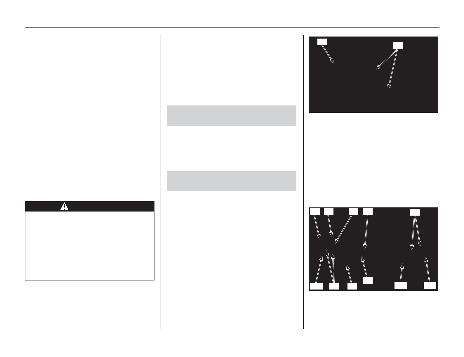
If You Have a Flat Tire
(cont’d)
Taking Care of the Unexpected 167
A flat tire is always unwelcome, especially if you
are far
from help. If you think you are losing air, or
you hit a pothole or hard object, pull safely to the
side of the road so you can inspect the tires and
assess the situation. (Be sure to park on a firm,
level surface and use the side stand for support.)
You should examine the tire treads and sidewalls
for foreign objects or damage.
If a tire has major damage or the bead has come
loose from the rim, there is probably not much you
can do except have your motorcycle transported to
your dealer or other qualified service facility. Even
with a simple puncture, this may be the safest and
least troublesome solution. For transporting
instructions, see page 158
Honda does not recommend that you make a
temporary repair to a tube-type tire. However, if
you decide to make a temporary repair so you can
get to a service facility, ride cautiously at reduced
speed and have the tube and tire replaced before
you ride again.
Due to the uncertainty of any temporary repair,
you should ride slowly (not over 30 mph, 50 km/h)
and carefully (preferably without a cargo) until the
tire and tube are replaced. Stop frequently and
check the air pressure. If the tire is losing pressure,
it may be unsafe to continue riding. As the tire gets
low, it will affect the handling of your motorcycle
(especially with a cargo) and it may overheat and
blow out.
We strongly recommend that you replace, not
repair, any tire or tube that is punctured or
damaged, even if the tire has only a minor
puncture. For a full discussion of repairs and
replacement, see the text beginning on page 127.
Refer to Important Safety Precautions on page 33.
We recommend wheel removal be done only by
your dealer or another qualified mechanic. Do not
attempt to remove the wheel on your own. Wheel
removal requires mechanical skill and professional
tools.
When removing and installing the wheel, be
careful not to damage the wheel speed sensor and
pulser ring (1).
Removal
1. Place your motorcycle on an optional
workstand or equivalent support with the front
wheel off the ground.
2. Remove the disc cover (2) by removing disc
cover socket bolts (3).
3. Remove the speed sensor wire guide plate
screw (4) and guide plate (5). Remove the speed
sensor mounting bolt (6) and speed sensor (7).
4. Remove the front axle nut (8) and loosen the
axle pinch bolts (9) on both forks. Pull the front
axle shaft (10) out of the wheel hub and
remove the front wheel and side collars (11).
• Avoid getting grease, oil, or dirt on the disc
or pad surfaces.
• Do not pull the brake lever while the wheel is
off the motorcycle.
WARNING
Riding your motorcycle with a temporary
tire or tube repair can be risky. If the
temporary repair fails, you can crash and
be seriously injured or killed.
If you must ride with a temporary tire or
tube repair, ride slowly and carefully and
do not exceed 30 mph (50 km/h) until the
tire or tube is replaced.
Should You Repair or Replace a Tire or
Tube?
Emergency Front Wheel Removal/
Installation
(2) disc cover (3) disc cover socket bolts
(1) pulser ring (8) front axle nut
(4) screw (9) axle pinch bolts
(5) plate (10) front axle shaft
(6) bolt (11) side collars
(7) speed sensor
(2)
(3)
(10) (11)
(9)
(5)
(1) (4)(6)(7)
(8)(9)(11)
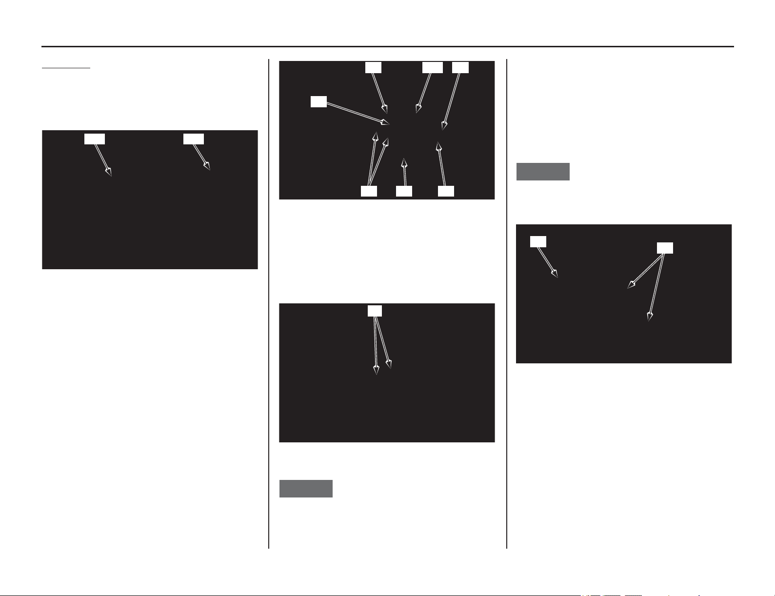
168 Taking Care of the Unexpected
If You Have a Flat Tire
Installation
1. Clean the surfaces where the axle and axle
clamps contact each other. Apply grease to
each dust seal lips of the front wheel.
Install the left side collar (12) and right side
collar (13) into the wheel hub.
2. Install the front wheel between the fork legs
while inserting the disc between the pads,
being careful not to damage the pads.
3. Insert the front axle shaft through the forks and
wheel hub from the right side. Make sure that
the front axle shaft is seated firmly onto the left
fork leg clamp inner surface. Tighten the front
axle nut (8) to the specified torque:
65 lbf·ft (88 N·m, 9.0 kgf·m)
Tighten the left axle pinch bolts (9) to the
specified torque:
15 lbf·ft (20 N·m, 2.0 kgf·m)
4. Route the speed sensor wire (14) properly and
install the speed sensor (7) to the left fork
bracket. Install and tighten the speed sensor
mounting bolt (6).
Install the speed sensor wire guide plate (5)
and tighten the guide plate screw (4).
5. While keeping the forks parallel, alternately
tighten the right axle pinch bolts (9) to the
specified torque:
15 lbf·ft (20 N·m, 2.0 kgf·m)
NOTICE
To avoid damage when torquing the axle pinch
bolts, be sure the axle is seated firmly onto the left
fork leg clamp inner surface.
6. Operate the front brake and pump the fork
several times. Check for free wheel rotation
after the brake is released. Recheck the wheel
if the brake drags or the wheel does not rotate
freely.
7. Install the disc cover (2) and tighten the disc
cover socket bolts (3) to the specified torque:
10 lbf·ft (13 N·m, 1.3 kgf·m)
NOTICE
Do not ride with the disc cover removed. Doing so
may damage the speed snsor wire.
If a torque wrench is not used for installation, see
your dealer as soon as possible to verify proper
assembly. Improper assembly may lead to loss of
braking capability.
(12) left side collar (13) right side collar
(12) (13)
(4) screw (8) front axle nut
(5) plate (9) axle pinch bolts
(6) bolt (14) speed sensor wire
(7) speed sensor
(9) axle pinch bolts
(4)
(5)(8)(9)
(7) (14)
(6)
(9)
(2) disc cover (3) disc cover socket bolts
(2)
(3)
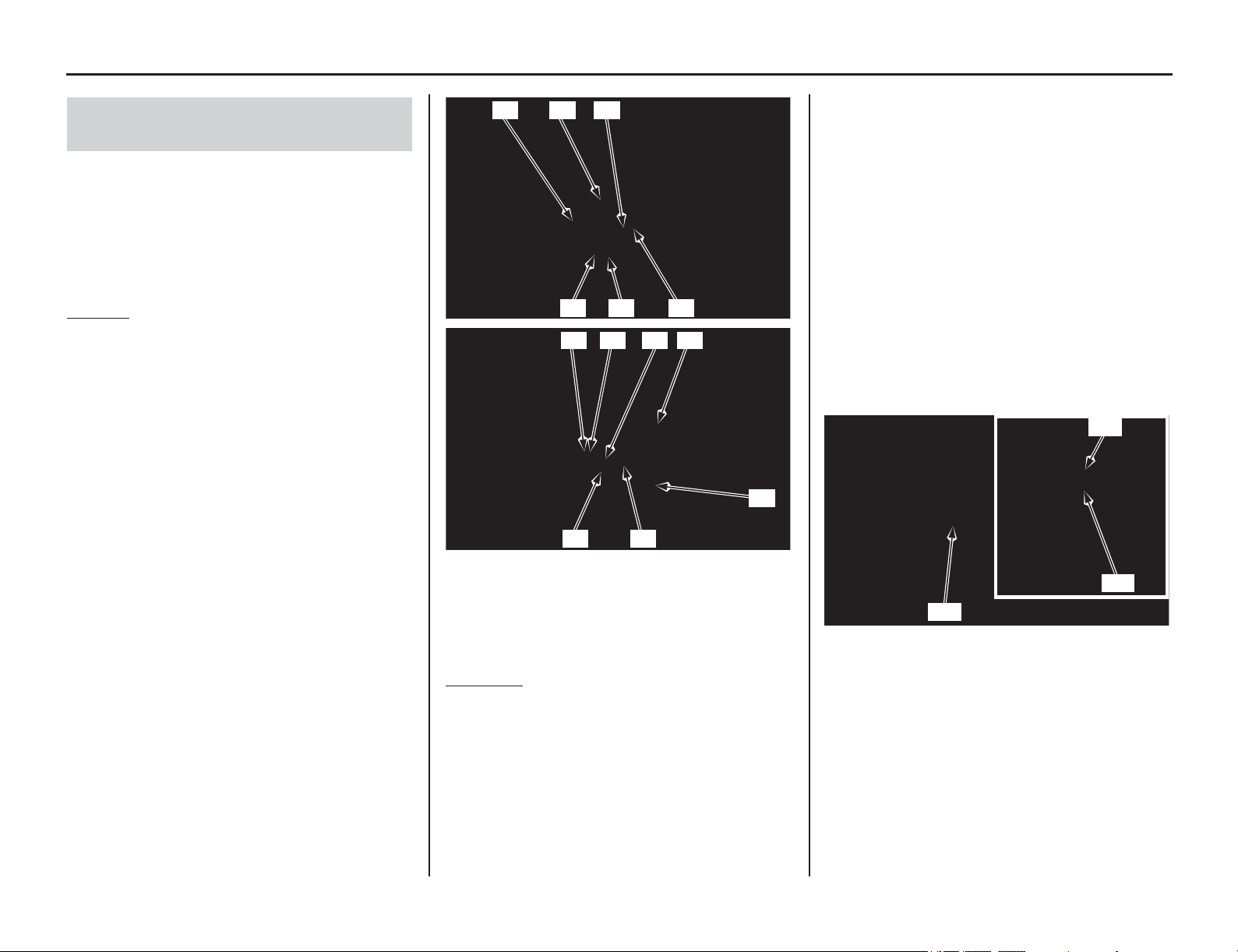
Taking Care of the Unexpected 169
If You Have a Flat Tire
Refer to Important Safety Precautions on page 33.
We recommend wheel removal be done only by
your dealer or another qualified mechanic. Do not
attempt to remove the wheel on your own. Wheel
removal requires mechanical skill and professional
tools.
Removal
1. Place your motorcycle on an optional
workstand or equivalent support with the rear
wheel off the ground.
2. Loosen the rear axle nut (1) and lock nuts (2) ,
and turn the adjusting bolts (3) so the rear
wheel can be moved all the way forward for
maximum drive chain slack.
3. Remove the rear axle nut.
4. Remove the drive chain (4) from the driven
sprocket (5) by pushing the rear wheel
forward.
5. Remove the rear axle shaft (6) and adjusting
plates (7).
6. Remove the brake caliper bracket (8), rear
wheel and side collars (9).
• Support the brake caliper assembly so that it
doesn't hang from the brake hose. Do not
twist the brake hose.
• Avoid getting grease, oil, or dirt on the disc
or pad surfaces.
• Do not push the brake pedal while the wheel
is removed.
Installation
1. Install the side collars and position the wheel
and rear brake bracket.
• While installing the wheel, carefully fit the
brake disc between the brake pads to avoid
damaging the pads.
• Avoid getting grease, oil, or dirt on the disc
or pad surfaces. Any contamination can
cause poor brake performance or rapid pad
wear after reassembly.
2. Make sure that the lug (10) on the caliper
bracket is positioned in the slot (11) on the
swingarm (12).
3. Insert the rear axle shaft from the left side,
through the left swingarm, wheel hub and
caliper bracket.
4. Install the drive chain by pushing the rear
wheel forward.
5. Install the rear axle nut and adjust the drive
chain slack. Refer to drive chain adjustment
(page 131).
6. Tighten the rear axle nut to the specified
torque:
94 lbf·ft (128 N·m, 13.1 kgf·m)
Failure to provide adequate disc-to-rear brake
bracket clearance may damage the brake discs
and impair braking efficiency.
7. After installing the wheel, apply the brakes
several times, then recheck both discs for
caliper holder to disc clearance. Do not operate
the motorcycle without adequate clearance.
If a torque wrench is not used for installation,
see your dealer as soon as possible to verify
proper assembly. Improper assembly may lead
to loss of braking capability.
Emergency Rear Wheel Removal/
Installation
(1) rear axle nut (6) rear axle shaft
(2) lock nuts (7) adjusting plates
(3) adjusting bolts (8) brake caliper bracket
(4) drive chain (9) side collars
(5) driven sprocket
(2)(1)(7)
(3)(9) (8)
(5)
(2) (3) (7) (4)
(9)
(6)
(10) lug (12) swingarm
(11) slot
(11)
(12)
(10)

If the High Coolant Temperature Indicator Lights
170 Taking Care of the Unexpected
If the High Coolant Temperature Indicator Lights
Normally, the temperature of the coolant in the
cooling system will rise to a level about midway
between cold and boiling. Hot weather may cause
the temperature to rise higher than normal. So will
temporary stress such as climbing a hill. If you’re
stuck in stop-and-go traffic, the temperature may
climb some, but the radiator fan is designed to
prevent overheating. Be aware of these variations.
If the high coolant temperature indicator (page 9)
comes on for no apparent reason, pull safely to the
side of the road. If possible, park in a shady area.
NOTICE
Continuing to ride with an overheated engine can
cause serious engine damage.
• A steaming engine indicates a coolant leak.
Shut the engine off and wait until the steaming
stops. Look for a leak, but don’t touch the
engine or radiator system. Let everything cool
off first.
• If there’s no obvious problem, leave the engine
on so the fan and coolant circulating system
can continue working. Monitor the high
coolant temperature indicator. The indicator
may turn off after a brief stop with no load on
the engine.
• Check the radiator fan.
If the fan is not working, turn the engine off.
Open the fuse box (page 172) and check the
radiator fan fuse. If the fuse is blown, replace it
with the proper (same rating) spare fuse. Start
the engine. If the high coolant temperature
indicator comes on and stays on, turn the
engine off.
If the radiator fan is working, visually check
the coolant level in the reserve tank. It isn’t
necessary to touch the radiator system.
• If the reserve tank is low or empty, don’t ride
without adding coolant (page 72). After adding
coolant, turn the engine on and check the high
coolant temperature indicator.
If the indicator doesn’t turn off, do not ride.
The engine needs repair. Transport your
motorcycle to your dealer (page 158).
If the temperature drops to normal, check the
coolant level. If it has gone down, add more
coolant.
If you are able to resume riding, continue to
monitor the high coolant temperature indicator
frequently.
If there’s a mild coolant leak, you can ride for
awhile, carefully watching the high coolant
temperature indicator. Be prepared to stop and add
more coolant or water. If the leak is bad, transport
your motorcycle to your dealer (page 158).
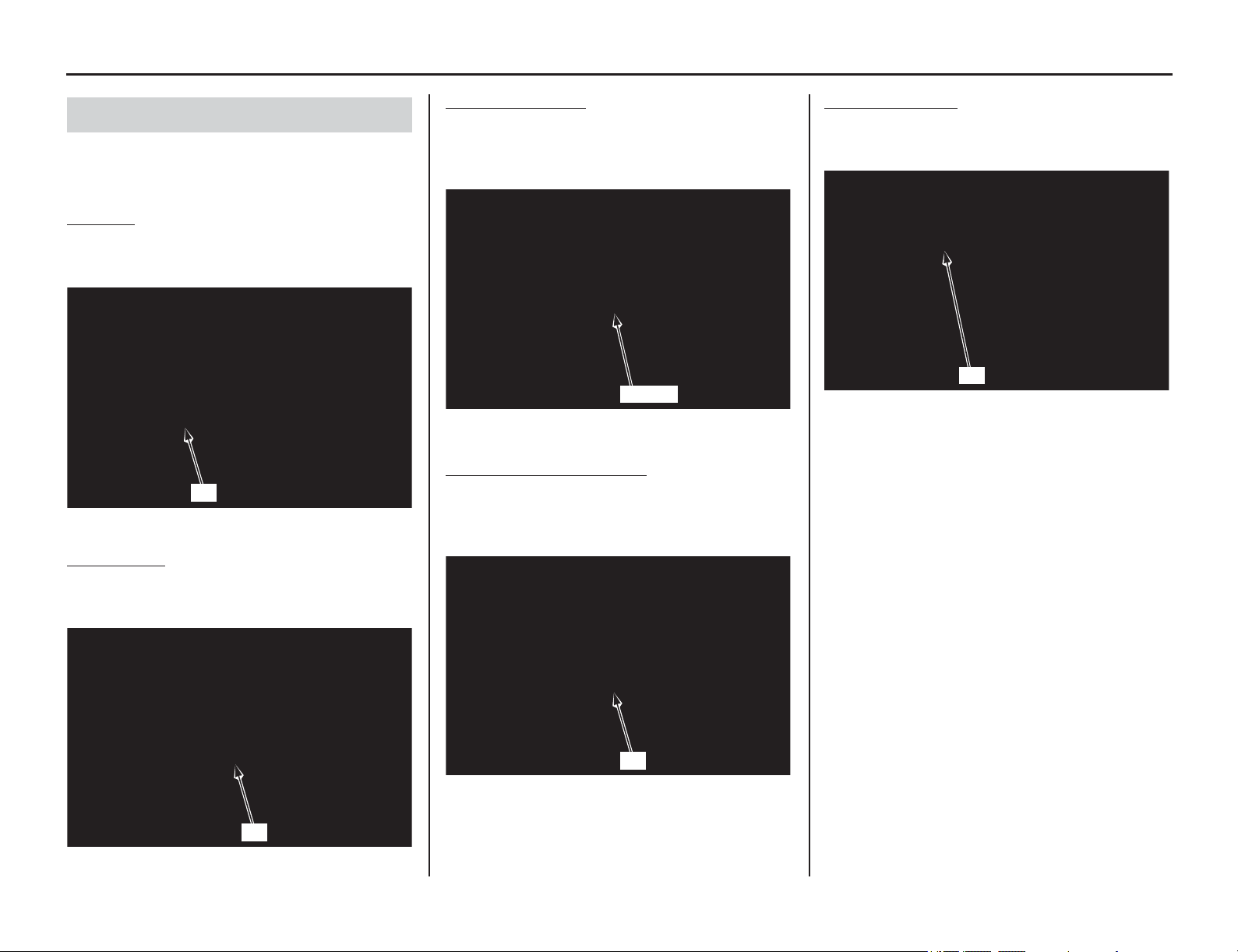
If You Have a Burned-out Light Bulb
Taking Care of the Unexpected 171
All light bulbs on the motorcycle are LEDs. If
there is an LED which is not turned on, see your
dealer for servicing.
Headlight
The headlight (1) uses several LEDs.
If there is an LED which is not turned on, see your
dealer for servicing.
Position Light
The position lights (1) use several LEDs.
If there is an LED which is not turned on, see your
dealer for servicing.
Brake light/Taillight
The brake light (1) and taillight (2) uses several
LEDs.
If there is an LED which is not turned on, see your
dealer for servicing.
Front/Rear Turn Signal Light
The front and rear turn signal lights (1) use several
LEDs.
If there is an LED which is not turned on, see your
dealer for servicing.
License Plate Light
The license plate light (1) uses an LED.
If there is an LED which is not turned on, see your
dealer for servicing.
Burned-out Light Bulb
(1) headlight
(1) position light
(1)
(1)
(1) brake light (2) taillight
(1) turn signal light
(1)(2)
(1)
(1) license plate light
(1)
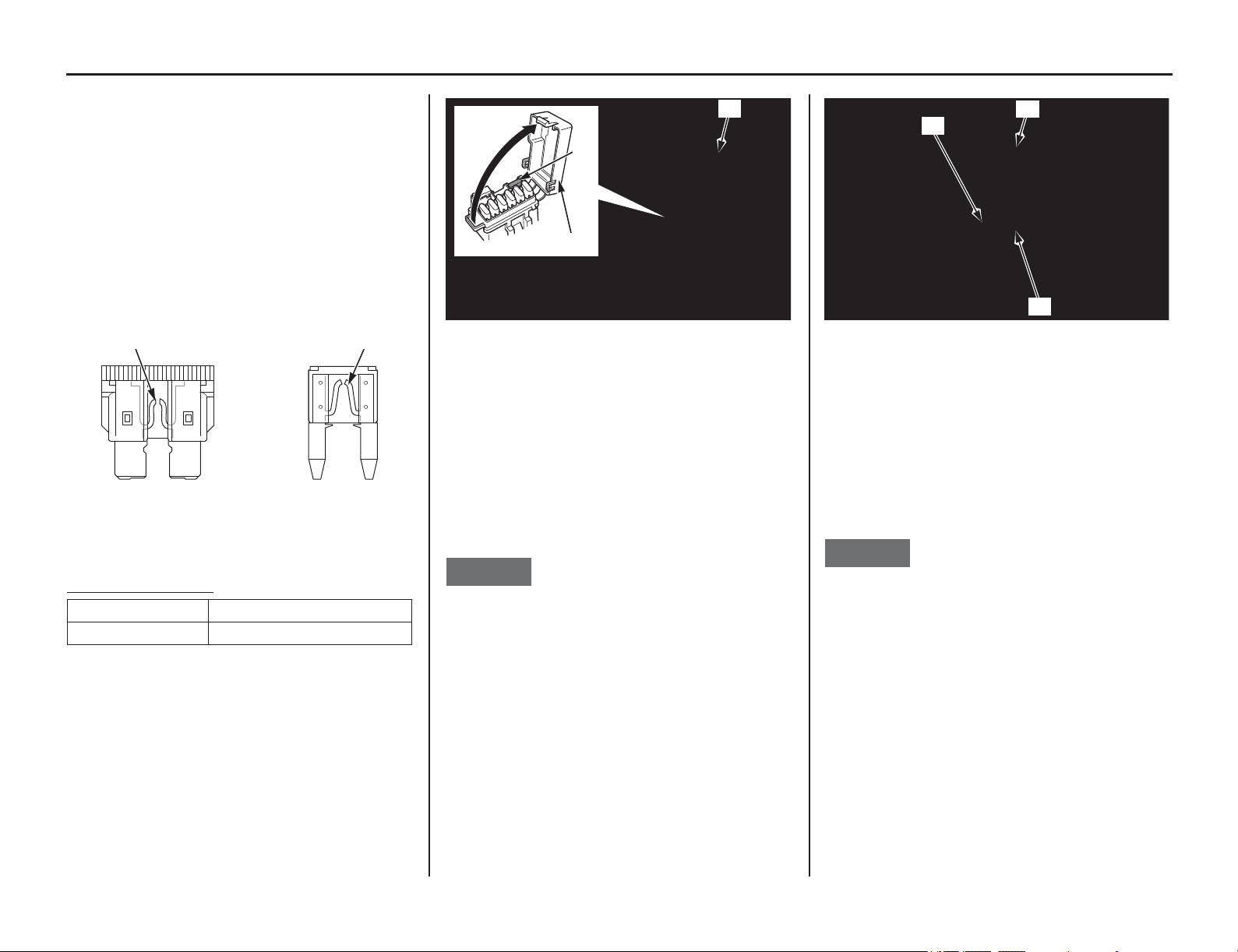
If a Fuse Blows
172 Taking Care of the Unexpected
If a Fuse Blows
All of the electrical circuits on your motorcycle
have a fuse to protect them from damage caused by
excess current flow (short circuit or overload).
If something electrical on your motorcycle stops
working, the first thing you should check for is a
blown fuse (1). Determine from the chart on the
circuit fuse box cover which fuse or fuses control
that component. Check the fuse before looking
elsewhere for another possible cause of the
problem. Replace a blown fuse and check
component operation.
The main fuse and circuit fuses are located on the
behind the left side cover.
Recommended Fuse
s
Circuit Fuses Access:
1. To prevent an accidental short circuit, turn the
ignition switch OFF before checking or
replacing the fuses.
2. Remove the seat (page 46).
3. Remove the left side cover (page 47).
4. Open the rubber fuse box cover (2) and fuse
box cover (3).
5. Pull out the fuses one by one to check for a
blown fuse. Always replace a blown fuse with
a spare of the same rating.
6. Close the fuse box cover and rubber fuse box
cover.
7. Install the left side cover (page 47).
8. Install the seat (page 46).
If you do not have a replacement fuse with the
proper rating for the circuit, install one with a
lower rating.
NOTICE
Replacing a fuse with one that has a higher rating
greatly increases the chance of damage to the
electrical system.
Main Fuse Access:
1. To prevent an accidental short circuit, turn the
ignition switch OFF before checking or
replacing the fuse.
2. Remove the seat (page 46).
3. Remove the left side cover (page 47).
4. Remove the start magnetic switch cover (5).
5. Pull out the main fuse (6) to check for a blown
fuse. Always replace a blown fuse with a spare
of the same rating.
6. Close the start magnetic switch cover.
7. Install the left side cover (page 47).
8. Install the seat (page 46).
If you do not have a replacement fuse with the
proper rating for the circuit, install one with a
lower rating.
NOTICE
Replacing a fuse with one that has a higher rating
greatly increases the chance of damage to the
electrical system.
If you replace a blown fuse with a spare fuse that
has a lower rating, replace the fuse with the correct
rating as soon as you can. Also remember to
replace the spare fuse that was installed.
If the replacement fuse of the same rating burns out
in a short time, there is probably a serious electrical
problem on your motorcycle.
Leave the blown fuse in that circuit and have your
motorcycle checked by your dealer.
(1) blown fuse
Main fuse 20 A
Other fuses 10 A
(1) (1)
(2) rubber fuse box cover
(3) fuse box cover
(4) spare fuse
(2)
(4)
(3)
(5) start magnetic switch cover
(6) main fuse
(7) spare main fuse
(5)
(6)
(7)

If You Crash
Taking Care of the Unexpected 173
Personal safety
is your first priority after a crash. If
you or anyone else has been injured, take time to
assess the severity of the injuries and whether it is
safe to continue riding. Call for emergency
assistance if needed. Also follow applicable laws
and regulations if another person or vehicle is
involved in the crash.
If you decide that you are capable of riding safely,
first evaluate the condition of your motorcycle. If
the engine is still running, turn it off and look it
over carefully; inspect it for fluid leaks, check the
tightness of critical nuts and bolts, and secure such
parts as the handlebar, control levers, brakes, and
wheels.
If there is minor damage, or you are unsure about
possible damage, ride slowly and cautiously.
Sometimes, crash damage is hidden or not
immediately apparent, so you should have your
motorcycle thoroughly checked at a qualified
service facility as soon as possible. Also, be sure to
have your dealer check the frame and suspension
after any serious crash.
If your motorcycle cannot be ridden, see
Transporting Your Motorcycle, page 158.
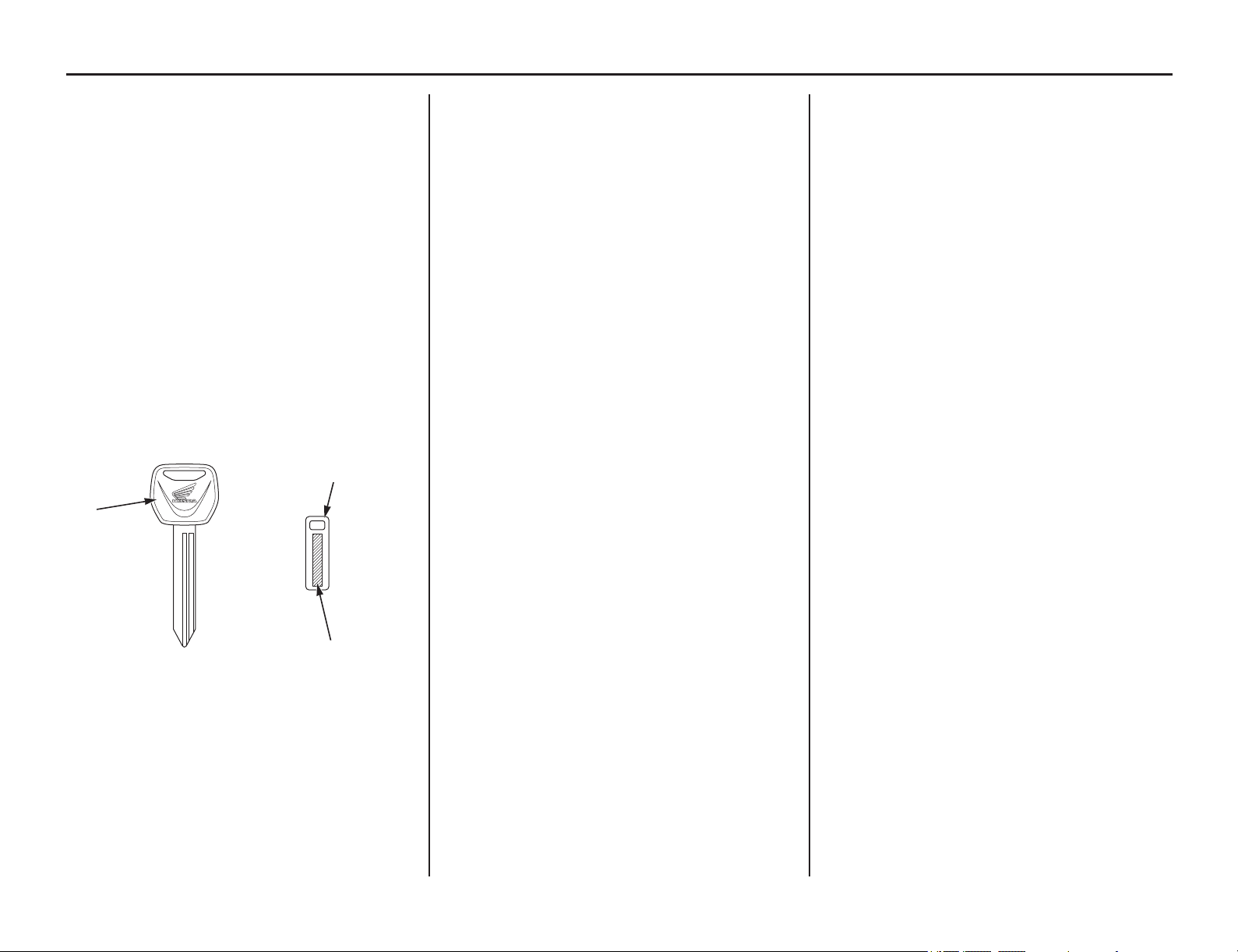
If You Lose Your Key
174 Taking Care of the Unexpected
If You Lose Your Key
Be sure to record your key number (1) provided
with the key number plate (2). Store the spare key
and recorded key number in a safe location. You’ll
need this number to have a duplicate key made.
A lost key won’t be a problem if you take
preventative action. Store one duplicate key in a
safe place at home and carry a second duplicate in
your wallet.
If you lose your key and aren’t carrying a
duplicate, either get your spare or have one made.
If you don’t know your key number, call the dealer
where you purchased your motorcycle. They may
have it listed in their records. If they don’t,
transport your motorcycle to them or the nearest
dealer. The dealer will probably have to remove
the ignition switch assembly to find the key
number so they can make a key for you.
(1) key number (2) key number plate
(3) ignition key
(2)
(1)
(3)

If Your Battery Is Low (or Dead)
Taking Care of the Unexpected 175
If an overvoltage, overcurrent, or short circuit is
applied, the battery fuse may blow.
Do not jump-start as this can damage your
motorcycle's electrical system and battery.
Bump starting is not recommended.
Check the battery voltage usi
ng a digital multi
meter with the cable connected.
Below 1V: The battery has failed; replace the
battery.
Between 1V and 8V: The battery may have
failed; charge the battery and then recheck. If
you can’t charge the battery or it appears
unable to hold a charge, see your dealer.

176 Taking Care of the Unexpected
BLANK PAGE

Technical Information
Technical Information 177
This section contains dimensions, capacities, and
other te
chnical data, plus information on
government requirements.
Vehicle Identification.....................................178
Serial Numbers ..........................................178
Specifications.................................................179
Torque Specifications ....................................181
Nuts, Bolts, Fasteners ................................181
Emission Control Systems .............................184
Exhaust Emission Requirements ...............184
Noise Emission Requirements...................184
Exhaust Emission Control System.............184
Evaporative Emission Control System ......184
Crankcase Emission Control System.........184
Fuel Permeation Emission Control System ...184
Noise Emission Requirements...................184
Problems Affecting Motorcycle Exhaust
Emissions ...................................................185
Catalytic Converter ........................................186
Oxygenated Fuels...........................................187
Off-Road Logbook.........................................188
Optional Parts List .........................................190
Spare Parts & Equipment...............................191
Spare Parts .................................................191
General Tools.............................................191
Honda Special Tools..................................191
Chemical Products .....................................191
Other Products ...........................................191
Wiring Diagram .............................................192
Vehicle Identification
178 Technical Information
Vehicle Identification
The VIN and engine serial number are required
when you register your motorcycle. They may also
be required when ordering replacement parts. You
may record these numbers in the Quick Reference
section at the rear of this manual.
The VIN (vehicle identification number) (1) is
stamped on the right side of the steering head and
also appears on the Safety Certification Label
attached to the right side of the frame.
The engine number (2) is stamped on the right
crankcase.
Serial Numbers
(1) VIN
(1) VIN
(1)
(1)
(2) engine number
(2)
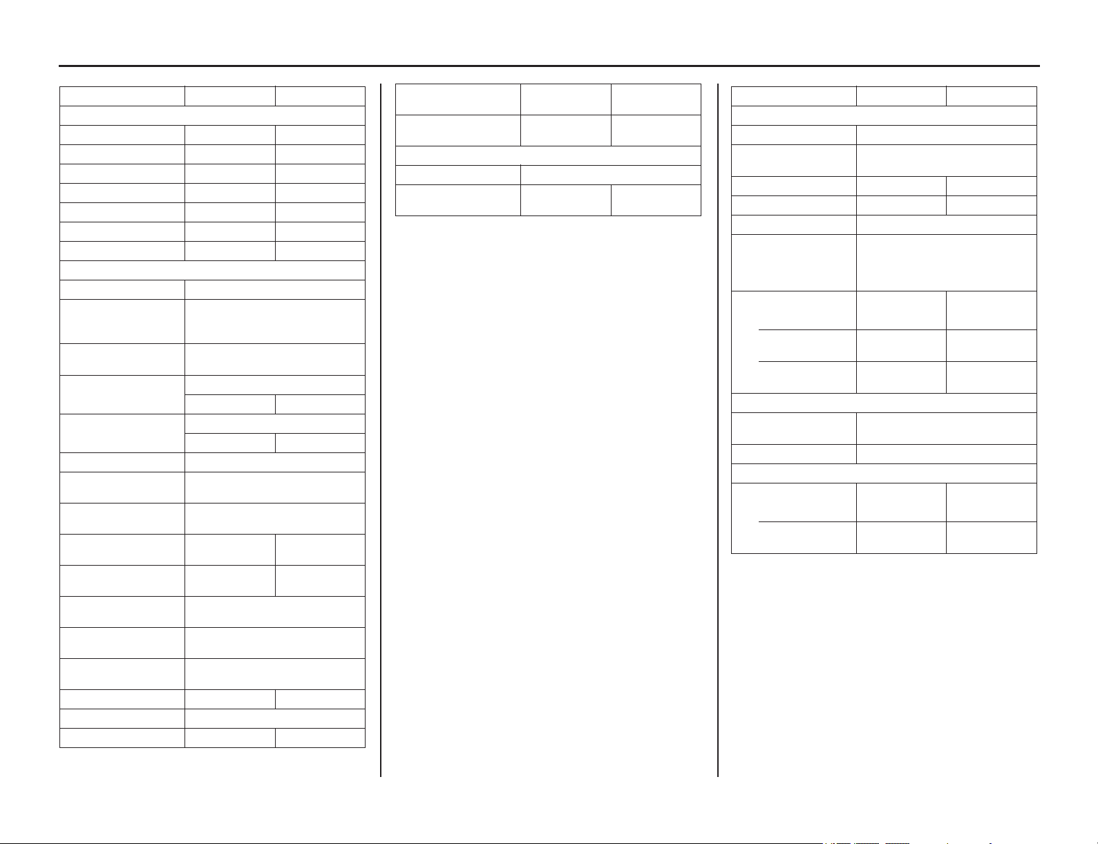
Specifications
(cont’d)
Technical Information 179
Item English Metric
Dimension
Overall length 89.8 in 2,280 mm
Overall width 32.5 in 825 mm
Overall height 49.6 in 1,260 mm
Wheelbase 59.1 in 1,500 mm
Seat height 37.0 in 940 mm
Footpeg height 15.7 in 400 mm
Ground clearance 12.4 in 315 mm
Frame
Type Twin tube
F. suspension
Telescopic fork,
travel 10.55 in (268 mm)
stroke 12.01 in (305 mm)
R. suspension
Pro-link,
travel 11.81 in (300 mm)
Tire size, front
80/100-21 M/C 51P
IRC GP-21F
Tire size, rear
120/80-18 M/C 62P
IRC GP-22R
Tire type bias-ply, tube
Tire pressure, front
(cold)
22 psi (150 kPa, 1.50 kgf/cm
2
)
Tire pressure, rear
(cold)
22 psi (150 kPa, 1.50 kgf/cm
2
)
Minimum tread
depth, front
0.12 in 3.0 mm
Minimum tread
depth, rear
0.12 in 3.0 mm
F. brake, swept area
Single disc brake
56.0 in
2
(361.0
cm
2
)
R. brake, swept
area
Single disc brake
60.5 in
2
(390.3
cm
2
)
Fuel
unleaded gasoline, pump octane
number of 91 or higher
Fuel tank capacity
2.01 US gal
7.6 ℓ
Caster angle 28°30’
Trail length 4.8 in 122 mm
Fork oil capacity
(except damper)
12.0 US oz 355 cm
3
Fork oil capacity
(damper)
8.2 US oz 243 cm
3
Capacities
Passenger capacity Operator only
Maximum weight
capacity
220 lb 100 kg
Item English Metric
Engine
Type Liquid cooled, 4-stroke
Cylinder
arrangement
Single 10° inclined
from vertical
Bore and stroke 3.78 x 2.44 in 96.0 x 62.1 mm
Displacement 27.4 cu-in 449 cm
3
Compression ratio 12.0 : 1
Valve clearance
(cold)
Intake: 0.004 ± 0.001 in
(0.11 ± 0.03 mm)
Exhaust:0.011 ± 0.001 in
(0.28 ± 0.03 mm)
Engine oil capacity
after draining 1.16 US qt 1.10 ℓ
after draining and
oil filter change
1.22 US qt 1.15 ℓ
after
disassembly
1.53 US qt 1.45 ℓ
Throttle body
Identification
number
GQ2HA
Idle speed 1,800 ± 100 rpm
Cooling system
Cooling capacity
after draining 1.20 US qt 1.14 ℓ
after
disassembly
1.31 US qt 1.24 ℓ
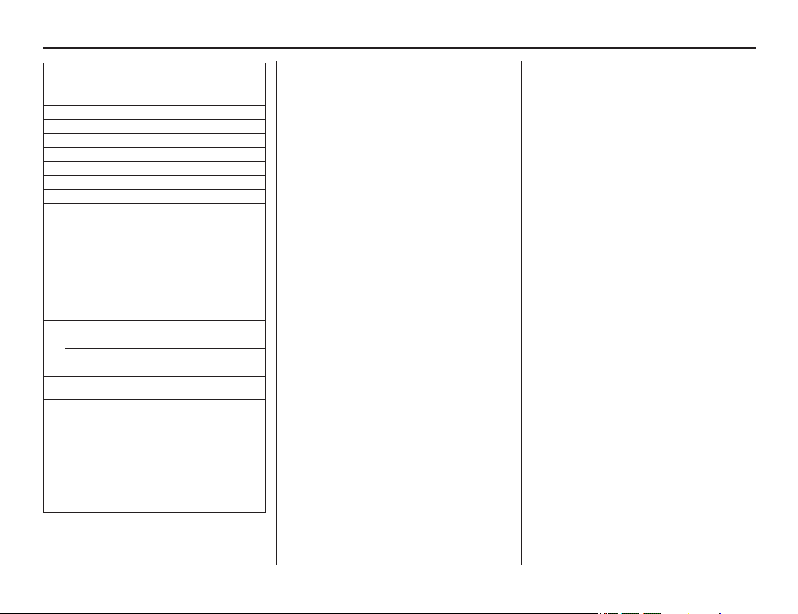
180 Technical Information
Specifications
Item English Metric
Drive train
Clutch type Wet, multi-plate type
Transmission 6-speed, constant mesh
Primary reduction 2.357
Gear ratio I 2.357
Gear ratio II 1.705
Gear ratio III 1.300
Gear ratio IV 1.090
Gear ratio V 0.916
Gear ratio VI 0.793
Final reduction 3.923
Gear shift pattern
Left foot-operated return
system 1-N-2-3-4-5-6
Electrical
Battery
HY93-C lithium-ion (li-ion)
12 V-4.5 Ah (20HR)
Ignition ECM
Starting system Electric
Spark plug NGK
Standard SILMAR9A-9S
For extended high
speed riding
NGK
SILMAR10A-9S
Spark plug gap
0.031 – 0.035 in
(0.8 – 0.9 mm)
Lights
Headlight LED
Brake/taillight LED
Turn signal light LED
Position light LED
Fuse
Main fuse 20 A
Other fuse 10 A
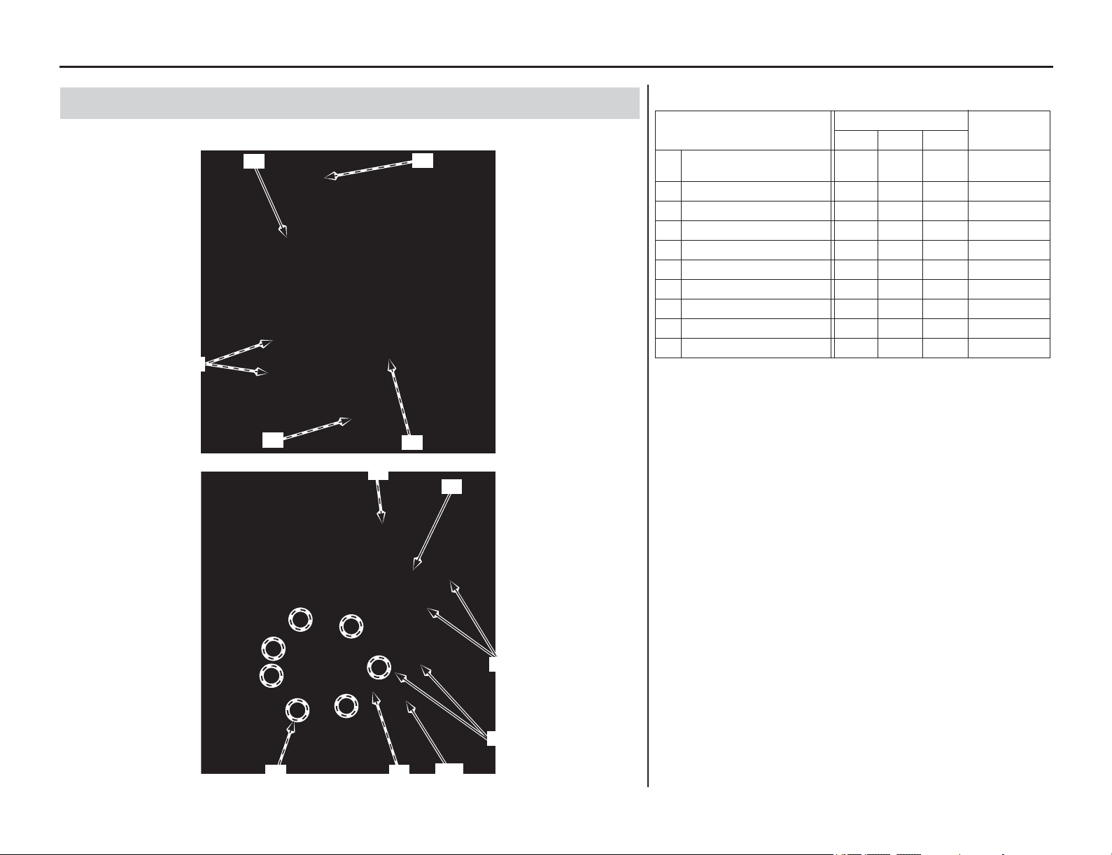
Torque Specifications
Technical Information 181
(cont’d)
Ch
eck and tighten nuts, bolts, and fasteners before every outing.
Nuts, Bolts, Fasteners
LEFT SIDE
(6)
(9)
(1)
(8)
(5)
RIGHT SIDE
(3)
(10)
(6)
(1)
(7)
(2)
(4)
ENGINE
Item
Torque
Remarks
lbf·ft N·m kgf·m
1 Cylinder head cover
socket bolts 7 10 1.0
2 Clutch cover bolts 7 10 1.0
3 Water pump cover bolts 7 10 1.0
4 Crankshaft hole cap 11 15 1.5 NOTE 1
5 Oil filter cover bolts 7 10 1.0
6 Cylinder head bolts 37 50 5.1 NOTE 2
7 Exhaust pipe joint nuts 16 22 2.2
8 Drive sprocket bolt 23 31 3.2
9 Engine oil drain bolt 13 18 1.8 NOTE 2
10 Coolant drain bolt 7 10 1.0
NOTES: 1. Apply grease to the threads.
2. Apply engine oil to the threads and seating surface.
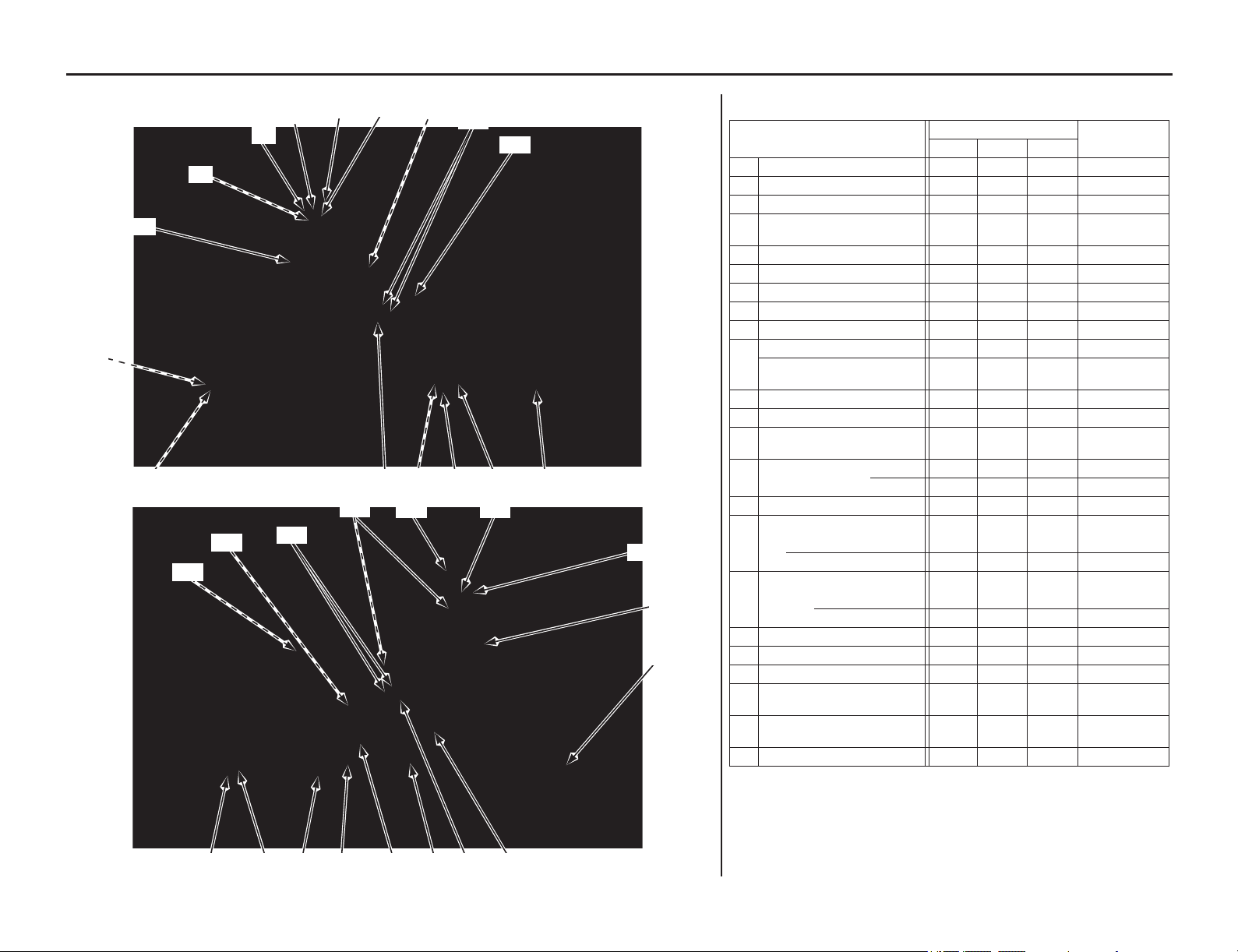
Torque Specifications
182 Technical Information
LEFT SIDE
(4)
(14)
(9)(14)(12)(6)
(3)
(7)
(5)
(2)
(1)
(21)
(18) (17)
(16)
(13)
RIGHT SIDE
(16)
(2)
(3)
(19)
(9)(8) (17)
(22)
(10)(18) (15)
(20)
(11)
(7)
(23)
(12)
(13)
FRAME
Item
Torque
Remarks
lbf·ft N·m kgf·m
1 Steering stem nut 80 108 11.0
2
Fork bridge upper pinch bolts
15 20 2.0
3
Fork bridge lower pinch bolts
15 20 2.0
4 Handlebar upper holder
bolts 16 22 2.2
5
Handlebar lower holder nuts
32 44 4.5 NOTE 1
6 Front axle nut 65 88 9.0
7 Axle pinch bolts 15 20 2.0
8 Rear axle nut 94 128 13.1 NOTE 1
9 Chain adjuster lock nuts 20 27 2.8 NOTE 2
10 Front engine hanger nuts 40 54 5.5
Front engine hanger plate
nuts 19 26 2.7
11 Lower engine hanger nut 40 54 5.5
12
Cylinder head hanger bolts
40 54 5.5
13 Cylinder head hanger
plate bolts 24 32 3.3
14 Rear suspension (upper) 32 44 4.5 NOTE 1
(lower) 32 44 4.5 NOTE 1
15 Swingarm pivot nut 65 88 9.0 NOTE 1
16 Fork
(fork damper assembly)
56 76 7.7
(fork bolt assembly) 22 30 3.1
17 Rear shock arm nuts
(swingarm side) 38 52 5.3 NOTE 1, 5
(shock link side) 38 52 5.3 NOTE 1, 5
18 Rear shock link bolts 27 37 3.8 NOTE 1, 5
19
Rear shock spring lock nut
32 44 4.5
20 Battery terminal bolts 1.5 2.0 0.2
21 Fuel pump mounting nuts/
cap nut
8111.1
22 Front brake master cylinder
holder bolts 7.3 9.9 1.0
23
Fuel tank bolts
7101.0
NOTES: 1. U-nut
2. UBS nut
5. Apply molybdenum oil to the threads and flange surface.
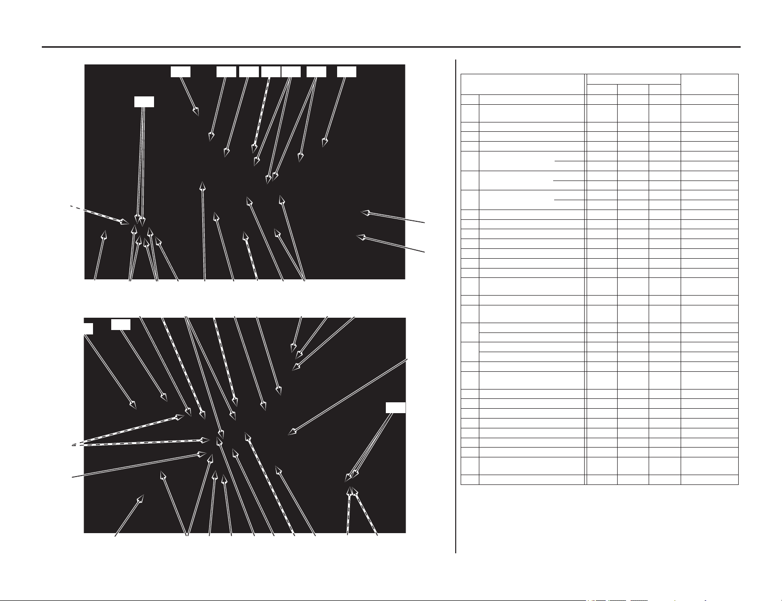
Torque Specifications
Technical Information 183
LEFT SIDE
(41) (53)
(29)
(37)
(38)(51)
(29)
(26)
(25)(34) (24) (46) (49) (50) (54) (30)
(31)(47)(48)
(35)
RIGHT SIDE
(28)
(46)
(48)
(47)
(41)
(24)
(24) (45)
(31) (53)(52)(51)
(51) (49)(36) (32)(33)
(35)
(38)
(39)
(40)
(44)
(42)
(27)
(43)
FRAME
Item
Torque
Remarks
lbf·ft N·m kgf·m
24 Brake hose oil bolts 25 34 3.5
25 Front brake caliper
mounting bolts 22 30 3.1 NOTE 4
26 Front brake disc nuts 12 16 1.6 NOTE 1
27 Rear brake disc nuts 12 16 1.6 NOTE 1
28 Brake pedal pivot bolt 27 36 3.7
29 Spokes (front) 2.7 3.7 0.4
(rear) 2.7 3.7 0.4
30 Drive chain roller (upper) 9 12 1.2 NOTE 4
(lower) 9 12 1.2 NOTE 1
31
Subframe bolts
(upper) 24 32 3.3
(lower) 36 49 5.0
32 Fork center bolt 51 69 7.0
33 Fork center bolt lock nut 21 28 2.9
34 Disc cover bolts 10 13 1.3
35 Fork protector socket bolts 5.2 7.0 0.7 NOTE 4
36
Muffler clamp bolt
15 20 2.0
37 Driven sprocket nuts 24 32 3.3 NOTE 1
38 Seat mounting bolts 19 26 2.7
39 Front brake reservoir cap
screws 0.7 1.0 0.1
40
Rear brake reservoir cap bolts
0.7 1.0 0.1
41 Fork air pressure release
screw 1.0 1.3 0.1
42 Muffler mounting bolt A 19 26 2.7
Muffler mounting bolt B 19 26 2.7
43
Tail cap cover bolts
6.6 9.0 0.9
Spark arrester mounting bolts
3.95.250.5
44
Throttle cable adjuster lock nuts
3.0 4.0 0.4
45 Rear master cylinder push
rod lock nut 4.4 5.9 0.6
46 Shroud A bolts 7 10 1.0
47 Shroud B bolts 7 10 1.0
48 Shroud C bolts 3.8 5.2 0.5
49
Engine guard A bolts/washers
7101.0
50 Engine guard B bolt/washer 7 10 1.0
51 Side cover bolts 7 10 1.0
52 Air cleaner retaining bolt 1.8 2.4 0.2
53 Seat support base
mounting bolts 7 10 1.0
54 Starter motor terminal bolt 5.2 7 0.7
NOTES: 1. U-nut
4. Alock bolt: replace with a new one.
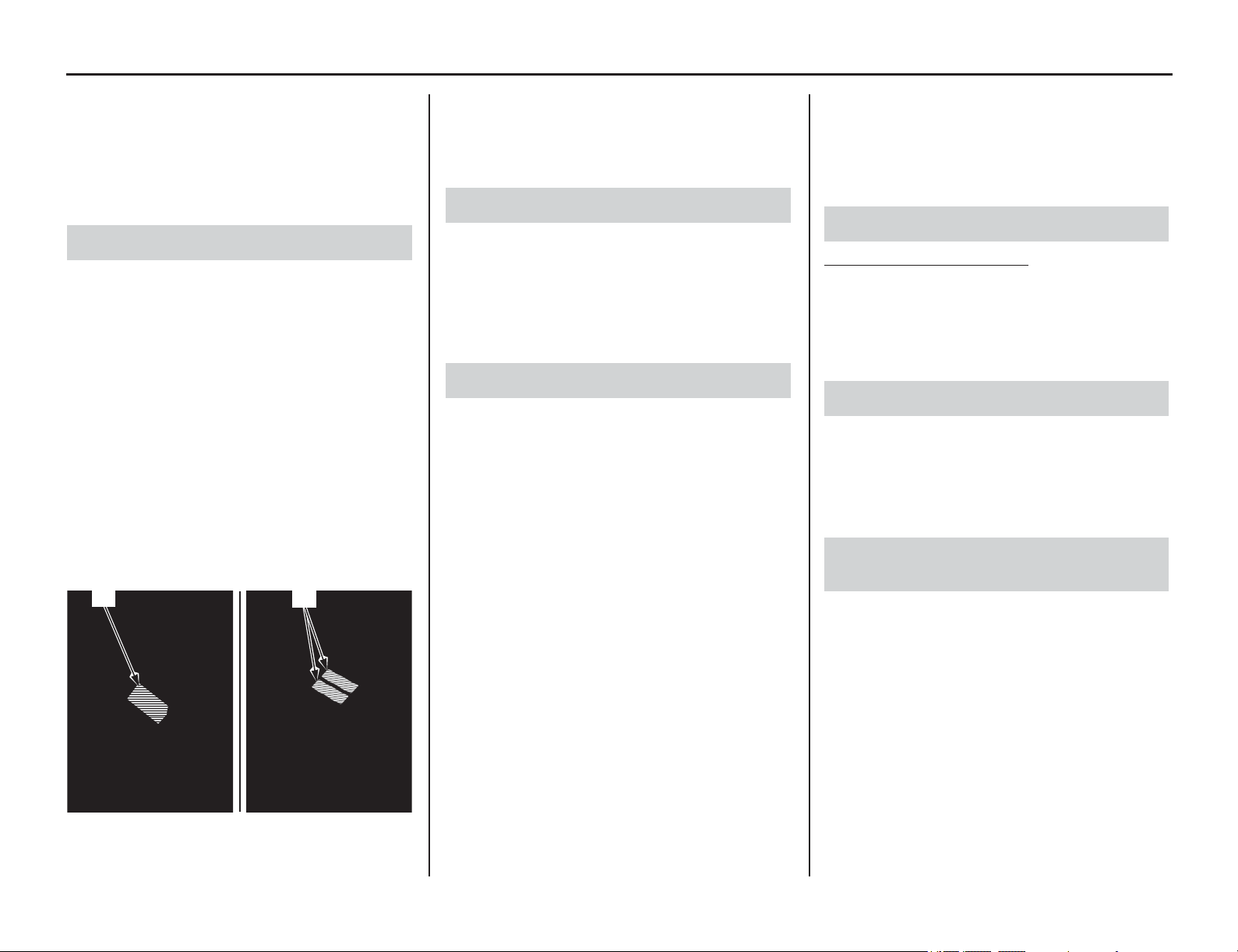
Emission Control Systems
184 Technical Information
Emission Control Systems
Your motorcycle engine emits combustion
byproducts, including carbon monoxide (CO),
oxides of nitrogen (NOx), and hydrocarbons (HC).
Gasoline evaporation also emits hydrocarbons.
Controlling the production of NOx, CO, and HC is
important for the environment.
The U.S. Environmental Protection Agency
(EPA), the California Air Resources Board
(CARB), and Environment and Climate Change
Canada (ECCC) require that your motorcycle
comply with applicable exhaust, crankcase, and
fuel permeation emission standards during its
useful life, when operated and maintained
according to the instructions provided. CARB also
requires that your motorcycle comply with
applicable evaporative emission requirements
during its useful life, when operated and
maintained according to the instructions provided.
Compliance with the terms of the Distributor's
Warranties for Honda Motorcycle Emission
Control Systems is necessary in order to maintain
a valid emissions system warranty. (USA only)
The Vehicle Emission Control Information label is
attached to the left side of the frame. (USA only)
The Vehicle Emission Control Information labels
are attached on the rear fender. (Canada only)
The EPA requires that motorcycles built after
January 1, 1983 comply with applicable noise
emission standards for one year or 3,730 miles
(6,000 km) after the time of purchase when
operated and maintained according to the
instructions provided.
The exhaust emission control system includes the
following components that should not need
adjustment, although periodic inspection by your
dealer is recommended.
PGM-FI System
The PGM-FI (programmed fuel injection) system
uses sequential multiport fuel injection, and is
comprised of air intake, engine control, fuel
control, and exhaust control subsystems. The
engine control module (ECM) uses sensors to
determine how much air enters the engine, and
then controls how much fuel to inject.
Ignition Timing Control System
The ignition timing control system adjusts the
ignition timing to reduce the amount of HC, CO,
and NOx produced.
Secondary Air Injection System
The secondary air injection system adds filtered air
into the exhaust gas to help improve emission
control performance.
Catalytic Converter
The exhaust system contains a catalytic converter.
Catalytic converter uses a catalyst to convert most
of the harmful exhaust gas compounds into
harmless compounds.
50 STATE (meets California)
An evaporative emissions control system uses a
canister filled with charcoal to adsorb fuel vapor
from the fuel tank while the engine is off. The
vapor is drawn into the engine and burned while
riding.
The engine is equipped with a closed crankcase
system to prevent discharging emissions into the
atmosphere. Blow-by gas is returned to
combustion chamber through the air cleaner
housing and throttle body.
The fuel tank, fuel hoses, and fuel vapor charge
hoses use fuel permeation control technologies to
prevent fuel vapor emissions. Tampering with
these components to reduce or defeat the
effectiveness of the fuel permeation technologies
is prohibited.
Exhaust Emission Requirements
(1) vehicle emission control information label (USA only)
(2) vehicle emission control information labels
(Canada only)
(1)
(2)
Noise Emission Requirements
Exhaust Emission Control System
Evaporative Emission Control System
Crankcase Emission Control System
Fuel Permeation Emission Control
System
Technical Information 185
Emission Control Systems
TAMPERING WITH THE NOISE CONTROL
SYSTEM IS PROHIBITED:
U. S. federal law prohibits, or Canadian provincial
laws may prohibit the following acts or the causing
thereof: (1) The removal or rendering inoperative
by any person, other than for purposes of
maintenance, repair or replacement, of any device
or element of design incorporated into any new
vehicle for the purpose of noise control prior to its
sale or delivery to the ultimate purchaser or while
it is in use; or (2) the use of the vehicle after such
device or element of design has been removed or
rendered inoperative by any person.
AMONG THOSE ACTS PRESUMED TO
CONSTITUTE TAMPERING ARE THE
FOLLOWING ACTS:
• Removal of, or puncturing the muffler, baffles,
header pipes or any other component which
conducts exhaust gases.
• Removal of, or puncturing of any part of the
intake system.
• Lack of proper maintenance.
• Removing or disabling any emissions
compliance component, or replacing any
compliance component with a noncompliant
component.
Have your motorcycle inspected and repaired by
your dealer if you experience any of the following
symptoms:
• Hard starting or stalling after starting
• Rough idling
• Misfiring or backfiring during acceleration
• Poor engine performance and poor fuel
economy
Noise Emission Control System Problems Affecting Motorcycle Exhaust
Emissions

Catalytic Converter
186 Technical Information
Catalytic Converter
This motorcycle is equipped with a three-way
catalytic converter. The catalytic converter
contains precious metals that serve as catalysts in
high temperature chemical reactions that convert
hydrocarbons (HC), carbon monoxide (CO), and
oxides of nitrogen (NOx) in the exhaust gasses into
safe compounds.
A defective catalytic converter contributes to air
pollution and can impair your engine's
performance. A replacement unit must be an
original Honda part or equivalent.
Follow these guidelines to protect your
motorcycle's catalytic converter.
• Always use unleaded gasoline. Leaded
gasoline will damage the catalytic converter.
• Keep the engine in good running condition. A
poorly running engine can cause the catalytic
converter to overheat causing damage to the
converter or the motorcycle.
• If your engine is misfiring, backfiring, stalling,
or otherwise not running properly, stop riding
and turn off the engine. Have your motorcycle
serviced as soon as possible.
Oxygenated Fuels
Technical Information 187
Some conventional gasolines are being blended
with alcohol or an ether compound. These
gasolines are
collectively referred to as oxygenated
fuels. To meet clean air standards, some areas of
the United States and Canada use oxygenated fuels
to help reduce emissions.
If you use an oxygenated fuel, be sure it is
unleaded and meets the minimum octane rating
requirement.
Before using an oxygenated fuel, try to confirm the
fuel’s contents. Some states/province require this
information to be posted on the pump.
The following fuel blends are EPA-approved and
have been approved for use in your motorcycle:
ETHANOL (ethyl or grain alcohol) up to 10% by
Volume
You may use gasoline containing up to 10%
ethanol by volume. Gasoline containing ethanol
may be marketed under the name “Gasohol”.
METHANOL (methyl or wood alcohol) up to 5%
by Volume
You may use gasoline containing up to 5%
methanol by volume as long as it also contains
cosolvents and corrosion inhibitors to protect the
fuel system. Gasoline containing more than 5%
methanol by volume may cause starting and/or
performance problems.
It may also damage metal, rubber, and plastic parts
of your fuel system.
If you notice any undesirable operating symptoms,
try another service station or switch to another
brand of gasoline.
Fuel system damage or performance problems
resulting from the use of an oxygenated fuel
containing more than the percentages of
oxygenates mentioned above are not covered
under warranty.
Oxygenated fuels can damage paint and plastic.
Be careful not to spill fuel when filling the fuel
tank. Wipe up any spills immediately.
NOTICE
Oxygenated fuels can damage paint and plastic.
Damage caused by spilled fuel is not covered by
warranty.

Off-Road Logbook
188 Technical Information
Off-Road Logbook
Any serious off-road effort relies heavily on the
knowledge gained and compiled from previous
racing events. The best way to organize the many
bits of information is to record them in a logbook.
Your logbook can include such information as
suspension adjustments, gearing, and tire
selection. This detailed information, along with
your comments, can prove valuable when you
compete at the same track or on similar terrain.
Your logbook can also tell you when maintenance
was performed and when it will be necessary
again. Your logbook also lets you record any
repairs and lets you keep track of the running time
on the engine and suspension components.
If you choose to sell your motorcycle, the accurate
maintenance records in your logbook might be the
deciding deal-maker for a potential buyer.
Consider using different color pens or pencils to
record important information on specific subjects.
For example, record results in black, suspension/
chassis settings in blue, and gearing selections in
green.
Color codes will help you identify the information
you want with a glance.
Tuning & Adjustment Records
Keep track of the settings and adjustments that
worked best at a particular location. These items
include:
• basic track conditions, altitude, and
temperature
• suspension settings
• chassis adjustments tested and selected
•gearing
• tire selection
• air pressure
Off-Road Records
• your placings
• thoughts to improve performance next time:
both yours and your motorcycle’s
• strategy notes
Maintenance Records
• regular interval maintenance
• repairs
• running time on engine
• running time on suspension components
Timekeeping
This Manual lists maintenance intervals for every-
so-many races or every-so-many hours of running.
Because all races are not the same, the most
effective way to schedule maintenance is by the
hours you have run your motorcycle.
An official “guesstimate” is close enough for our
timekeeping purposes. You may choose to record
your time the same way aircraft operators do (but
without the benefit of an electrical hourmeter).
All running time is broken down into hours and
tenths of an hour (each 6 minutes represents one
tenth of an hour).
Racing Records
Information worth recording for this section of
your logbook may include:
• Your placing in each race and overall finishing
position.
• Thoughts on what you could do to improve
your performance next time.
• Notes on any patterns noted in choice of
starting gate positions or in riding portions of
the course as the day progressed that may
prove helpful in future events.
• Any places on the course where you chose the
wrong line and were passed too easily.
• Notes on strategy used by your competition or
by riders in another event that are worth
remembering.
Maintenance Records
Regular maintenance items you’ll want to record
in your logbook should include:
• Dates and results of cylinder, piston and ring
examinations
• Patterns for frequency of need for
decarbonization with a particular oil
• When you last performed shock linkage and
swingarm pivot bearing maintenance
• Engine and suspension oil changes
• Chain, sprocket, chain roller and slider
replacements
• Coolant changes and related component
replacements
• Spark plug, brake pad and control cable
replacements
In addition, you should record any irregularities
noted in component wear so you’ll remember to
keep a close eye on these areas in the future.
Off-Road Logbook
Technical Information 189
Date Running
Time
Location/Event Comments (Suspension Settings, Gearing, Chassis Adjustments, Maintenance Performed, etc.)
(Make several photocopies of this page for future use)
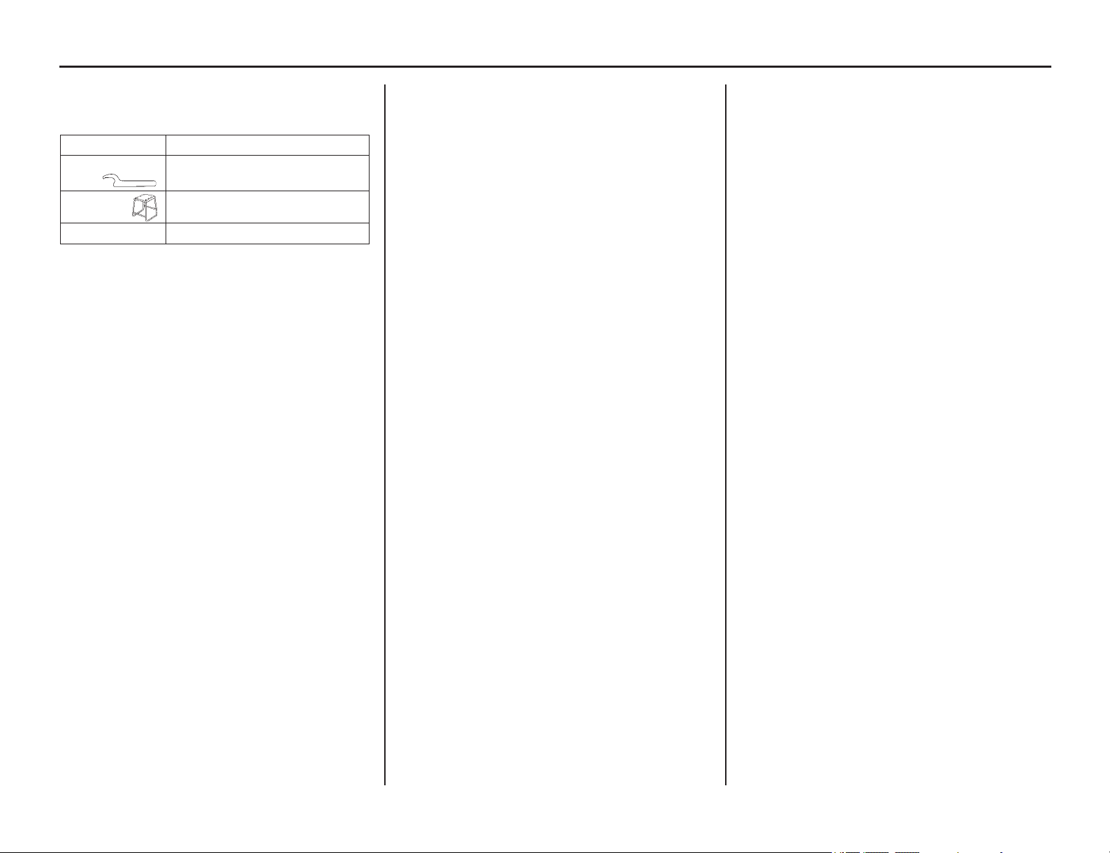
Optional Parts List
190 Technical Information
Optional Parts List
These tools may be ordered from your authorized
dealer.
TOOLS Remarks
Pin spanner A To adjust spring preload.
(two spanners required)
Workstand For maintenance
Air gauge For checking tire air pressure

Spare Parts & Equipment
Technical Information 191
There are
numerous spare parts you can take to an
event to help ensure you get in a full day of riding.
In addition to the usual nuts and bolts, consider the
following:
spark plugs
air cleaner (clean & oiled, sealed in a plastic bag)
chain & masterlinks
chain guide slider
chain guide
chain rollers
tire tubes (front & rear)
fenders
footpegs
fuel feed hose
fuel pump filter
number plate & side covers
handlebar
grips
levers (brake & clutch)
clutch lever handlebar mount
clutch cable
throttle assembly
throttle cable
shift lever
brake pedal
spokes (front & rear, each side)
sprockets (larger & smaller than standard)
assorted nuts, bolts, washers, screws, cotter pins
Additional Spares
fuel pump
front brake master cylinder
rear brake assembly
wheels & tires (front & rear, mounted)
clutch discs and plates
engine oil
seat
ignition components
radiator hoses
radiator shrouds (L & R)
brake hoses (front & rear)
sockets (3/8 in drive)
screwdrivers: blade & Phillips No. 1, 2, 3
wrench, large adjustable
wrenches: open end & box
wrenches: hex (Allen)
wrench, spoke
torque wrench (metric scale, click-stop style)
pliers: standard, needle-nose, channel-lock set
hammer, plastic head
syringe with adjustable stop
air pressure gauge
tire irons
tire pump or air tank
feeler gauge set
vernier caliper (metric)
pressure/vacuum testing equipment
Any special tools for your motorcycle purchased
from your dealer.
• Tensioner stopper 07AMG-001A100
• Lock Nut Wrench 07WMA-KZ30100
• Spoke Wrench 07JMA-MR60100
• Spoke Wrench 070MA-KZ30100
• Piston Base 07958-2500001
• Fork Rod Holder 07AMB-KZ3A100
(USA only)
Pro Honda GN4 4-stroke Oil
(Engine Oil)
Pro Honda HP Fork Oil, SS-19
Honda DOT 4 Brake Fluid
Pro Honda HP Chain Lube
Pro Honda Foam Air Filter Oil
Pro Honda Hondabrite
Pro Honda Dielectric Grease
Pro Honda Handgrip Cement
Pro Honda Hondalock
Molybdenum disulfide grease (containing more
than 3% molybdenum disulfide additive Moly
Paste 77)
Pro Honda Foam Air Filter Sealer
Multi-Purpose Grease
Rust-inhibiting oil
Cable lubricant
Pro Honda HP Coolant
Urea based multi-purpose grease designed for high
temperature, high pressure performance
(example: EXCELITE EP2 manufactured by
KYODO YUSHI, Japan or equivalent)
pliers-safety wire
safety wire
mechanic’s wire
duct tape
plastic wire bands
hose clamps
drop light
electrical tape
Scotch-Brite Hand Pad #7447 (maroon)
Teflon tape
Spare Parts
General Tools
Honda Special Tools
Chemical Products
Other Products
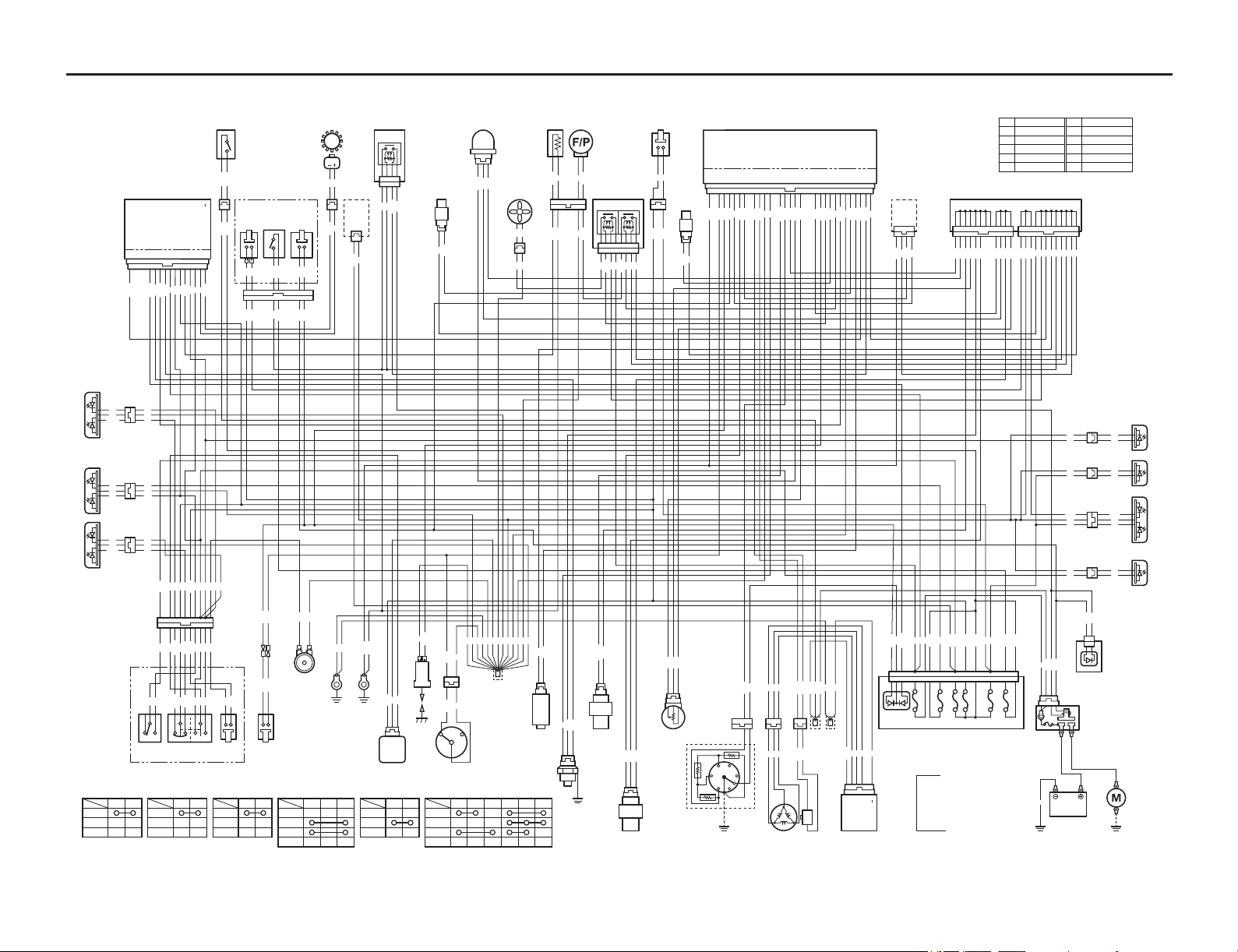
Wiring Diagram
192 Technical Information
2P (O)
3P
2P
2P (Lb)
OUT
Vcc
GND
IGN
GND
ST
IG
BAT
BAT
IGN
GND
LOAD
IG BAT
HL
LO
HI
PR
P
PL
L
W
R
UP
DOWN
1
N
2
34
6
5
V
(
+
)
CHARGE
CHARGE
CHARGE
V
()
1
2
3
4
5
6
7
8
9
10
11
12
13
14
15
16
LG
SSTAND
NL SW
START SW
SCS
PB
K-LINE
PCP
PCM
PG 2
TW
TA
GPAD
SG
BA
THL
VCC
IGPLSE
FANC
PCS
FLR
FI IND
PG 1
EX-AI
INJ 1
FLCNT
START RELAY
IGP
A-33
A-32
A-31
A-30
A-29
A-28
A-27
A-26
A-25
A-24
A-23
A-22
A-21
A-20
A-19
A-18
A-17
A-16
A-15
A-14
A-13
A-12
A-11
A-10
A-9
A-8
A-7
A-6
A-5
A-4
A-3
A-2
A-1
FUEL PULSE
(TxD)
(RxD)
(NS TEST)
NEUTRAL
TEMP
ENG
GROUND
BATTERY
HIGH BEAM
IGNITION
FUEL RES
TURN RIGHT
TURN LEFT
SPEED SENSOR
(
+
)
SPEED SENSOR
()
WPC
4P
(
R
)
WPC
33P
(
Bl
)
GND
IGN
K-LINE
SCS
WPC
24P
(
W
)
WPC
24P
(
W
)
WPC
2P
(
Bl
)
WPC
2P
WPC
2P
(
Bl
)
WPC
2P
(Bl)
WPC
2P
WPC 7P (G)
WPC 7P (G)
10P
(Gr)
WPC 3P (Bl)
WPC
2P
(Bl)
2P
(Br)
8P
(Gr)
16P
(Gr)
4P
WPC
3P
(Bl)
WPC
8P
(Gr)
WPC
5P
3P
MINI
(
Bl
)
WPC
2P
(
Gr
)
WPC
2P
(
Bl
)
WPC
3P
(
Gr
)
WPC
3P
(Bl)
WPC
2P
(
Bl
)
WPC
3P
(
Bu
)
WPC
5P
(
Bl
)
WPC
2P
(Bl)
WPC
2P
(Bl)
WPC
3P
(Gr)
Y/BlCOLOR
FREE
PUSH
R/Bl
STBAT
Bl/WCOLOR
FREE
PUSH
R/Y
IGBAT
R/WCOLOR
OFF
ON
Bl/R
IGBAT
Bl/YCOLOR
PUSH
FREE
Lg
HOBAT
WCOLOR
(
N
)
LO
Bu
HIHL
-
LO
HI
GrCOLOR
N
R
OBl
Lb/W O/W
L P PR PLW
Lb
R
L
WPC
4P
(Bl)
2P
O
G
O
G
G
G/Y
G
G/Y
G
Br
G
Br
G
Br
Bl
G
Lb
G
Lb
G
W
Lb
G
Lb/W
Br
Bl
Gr
W
G
Bu
O
G
W
R/Bl
Gr
W
Br
W
Bl/Y
Bu
O
Lb
Lg
Lb
O
W
Gr
Lb/W
Bl
O/W
Bl/Y
Bu
O
Lb
Lg
O
G
O/W
Lb/W
Bl
O/W
O
Gr
Lb
Bl/Y
G
Gr
P
G/R
Y/G
G/Y
G/R
R/Y
Y/G
G/R
R/Y
Y
Y
Y
R/W
R/W
R/W
R/W
Y
Y
Y
G
G/Bl
Lg
Lg/Bl
R
R
R
Bl/R
R
R/W
Y/R
Br/Y
Br/Y
Y/R
W
R/Bl
R/Bl
Bl/Y
Bl/R
G
G
G/W
G
G/O
G
W
Bu
Lg
Bl/Y
G/Bl
G/O
G/Bl
G/O
G
G
G
Y/Bu
Bl
P/W
Gr/Bu
G/R
Bl/G
Lg
Bu/Y
W/Y
Y
Y
Y
Bu/Y
W/Y
G
G
G
G
G
G
G
G
G
G
G
G
G
G/W
G/W
Lg
G
Lb
BATTERY
12V 4.5AH
Bl
Bl
R/W
Bl/R
R/W
Bl/R
Bl/W
Bl/G
Br/Y
Y/R
W/R
P
R/Bl
G
Bl
P/Bl
R/Bu
R/Y
G/R
Bu
G
Y/W
G
G
Br/R
Y/W
G/W
G
Br/R
Bl
Bl
G/W
G/O
G/Bl
Br/Y
Bu
G/Y
O/Bl
W/Y
Bu/Y
G
P
Gr/Bu
Bl/O
G/R
R/Bu
Y/G
R/Y
Y/Bu
Br/W
Y/Bl
W
W/Bu
G
P/Bl
P/W
Bu/R
Lg/Bl
Bl
Y/Bl
Bl
G/W
Bl
O/Bl
Bu
G/R
G/R
G/R
G/R
G/R
G/R
R/Y
R/Y
R/Y
R/Y
G/Y
G/Y
G/Y
Bl
Bl
Bl
Bl
Bl
Bl
Bl
Bl
Bl
Bl/Y
G/Y
Bu
G
Bu
Br/W
Bl
R
Br/R
W
Bl
Bl
Bl
Bl
Lg/Bl
Y/R
W
Bu
Bl/Y
G/Y
Bu/R
Lg/Bl
Y/G
W/Bu
G/W
R
Bu
Br
Y/W
Lb
O
P
W/R
Bl
Bl/G
Br/Y
G/Bl
Br
Br
Bl/G
Bl/R
REAR RIGHT
TURN SIGNAL LIGHT
REAR LEFT
TURN SIGNAL LIGHT
LICENSE LIGHT
FRONT RIGHT
TURN SIGNAL LIGHT
FRONT LEFT
TURN SIGNAL LIGHT
HEADLIGHT
BRAKE/TAIL LIGHT
STARTER
MOTOR
MAIN
FUSE
(20A)
STARTER
RERAY
SWITCH
ENGINE
GROUND
ENGINE
GROUND
COLOR COMB : GROUND / MARKING
Bl
Br
Bu
G
Gr
Lb
Black
Brown
Blue
Green
Gray
Light Blue
Lg
O
P
R
W
Y
Light Green
Orange
Pink
Red
White
Yellow
JUNCTION
STARTER
RERAY
DIODE
DIODE
ABCDEF
FUEL
PUMP
RELAY
FAN
RELAY
BANK ANGLE
SENSOR
EXHAUST
AIR INJECT
SOLENOID
VALVE
STARTER
SWITCH
ENGINE
STOP
SWITCH
FRONT
BRAKE
LIGHT
SWITCH
REAR BRAKE
LIGHT SWITCH
FRONT WHEEL
SPEED SENSOR
COMBINATION METER
IGNITION SWITCH
ACCESSORY
RIGHT HANDLE SWITCH
LEFT HANDLE SWITCH TURN SIGNAL
RELAY
INJECTOR
SIDE STAND
SWITCH
REGULATOR/
RECTIFIER
FUSE BOX
WELDING
JOINT
WELDINGJOINT
FRAME
GROUND
FRAME
GROUND
GROUND
GROUND AC
GENERATOR
CKP
SENSOR
TP SENSOR
IAT SENSOR
IGNITION
COIL
ECT
SENSOR
MAP SENSOR
HORN
DLC
ECM
PURGE
CONTROL
SOLENOID
VALVE
FAN
MOTOR
FUEL
PUMP
THERMISTOR
FUSE
A 10A FAN,CLOCK
B 10A HEADLIGHT LO
C 10A HEADLIGHT HI
D 10A TURN SIGNAL,STOP
E 10A ILLUMI
F 10A FI
STARTER SWITCH ENGINE STOP SWITCH IGNITION SWITCH HORN SWITCHDIMMER SWITCH TURN SIGNAL SWITCH
DIMMER
SWITCH
TURN SIGNAL
SWITCH
HORN
SWITCH
CLUTCH
SWITCH
GEAR
POSITION
SWITCH

Consumer Information
Consumer Information 193
This sect
ion contains information about contacting
Honda and how to get an official Honda Service
Manual.
Authorized Manuals.......................................194
Warranty Coverage ........................................195
Warranty Service ...........................................196
Contacting Honda ..........................................197
Your Honda Dealer ........................................198
Reporting Safety Defects (USA only) ...........199
Authorized Manuals
194 Consumer Information
Authorized Manuals
The Service Manual used by your authorized dealer is available from your
Honda dealer or Helm, Inc. (USA only, Canada: See your dealer to order
authorized manuals.)
Also available but not necessary to service your model is the Honda Common
Service Manual which explains theory of operation and basic service
information for various systems on Honda motorcycles, scooters and ATV.
The Winter Storage Guide in conjunction with the Owner's Manual and
Service Manual can help you prepare your Honda motorcycle, scooter, ATV,
and SxS for winter storage (USA only).
These Honda manuals are written for the professional technician, but most
mechanically-capable owners should find them helpful if they have the proper
tools and skills. Special Honda tools are necessary for some procedures.
USA only: Order On-Line: www.helminc.com
Order Toll Free: 1-888-CYCLE93 (1-888-292-5393)
(NOTE: For Credit Card Orders Only)
Monday - Friday 8:00 AM - 6:00 PM EST
Publication Item No. Description
61MKE50 2019 CRF450L Service Manual
61CSM00 Common Service Manual
S9507 Winter Storage Guide
31MKE900 2019 CRF450L Owner’s Manual

Warranty Coverage
Consumer Information 195
Your new Honda
is covered by the following
warranties:
• Motorcycle Limited Warranty
• Emission Control System Warranty
• Noise Control Warranty (USA only)
The responsibilities, restrictions, and exclusions
that apply to these warranties are explained in the
Warranties Booklet given to you by your Honda
dealer at the time of purchase. Always keep your
Honda owner's card with your Warranties Booklet.
Canada: Please refer to the Warranty Booklet
posted on our website at www.honda.ca.
It is important to realize that your warranty applies
only to defects in material or workmanship of your
Honda. Your warranty coverage does not apply to
the normal wear and deterioration associated with
use of the motorcycle.
Your warranty coverage is not voided if you
perform your own maintenance. However, failures
that occur due directly to improper maintenance
are not covered by these warranties.
You can extend almost all of your warranty
coverage through the Honda Protection Plan. For
more information, see your Honda dealer. (USA
only)

Warranty Service
196 Consumer Information
Warranty Service
Please remember that maintenance recommended
in the Maintenance Schedule is not included in
your warranty coverage. If you believe you have a
problem with your motorcycle, call the service
department of your Honda dealer. Make an
appointment for an inspection and diagnosis. You
will be asked to authorize that inspection, and your
dealer will return the results of the inspection. If a
problem exists and is covered under warranty, your
dealer will perform the warranty repairs. If you
have any questions about your warranty coverage
or the nature of the repair, talk to the Service
Manager of your Honda dealer.
If a misunderstanding occurs and you aren't
satisfied with your dealer's handling of the
situation, we suggest you discuss your problem
with the appropriate member of the dealership's
management team. If you are still not satisfied,
contact the owner of the dealership or their
designated representative.

Contacting Honda
Consumer Information 197
Your owner’s manual was written to cover most of
the questions you might ask about your motorcycle.
Any questions not answered in the owner’s manual
can be answered by your dealer. If your dealer
doesn’t have the answer right away, they will get it
for you.
If you have a difference of opinion with your
dealer, please remember that each dealership is
independently owned and operated. That’s why
it’s important to work to resolve any differences at
the dealership level.
If you wish to comment on your experiences with
your motorcycle or with your dealer, please send
your comments to the following address:
Motorcycle Division,
American Honda Motor Co., Inc.,
P.O. Box 2200, Torrance,
CA 90509- 2200
Mailstop: 100-4C-7B,
Telephone: (866) 784-1870.
Canada: Honda Canada Inc.
Customer Relations Department,
180 Honda Boulevard
Markham, Ontario
L6C 0H9
Telephone: (888) 946–6329
Fax: (877) 939–0909
E-mail: [email protected]
Please include the following information in your
letter:
• Name, address, and telephone number
• Product model, year, and VIN
• Date of purchase
• Dealer name and address
We will likely ask your Honda dealer to respond, or
possibly acknowledge your comments directly.

Your Honda Dealer
198 Consumer Information
Your Honda Dealer
Once you purchase your new Honda, get familiar
with the organization of your Honda dealer so you
can utilize the full range of services available.
The service department is there to perform regular
maintenance and unexpected repairs. It has the
latest available service information from Honda.
The service department will also handle warranty
inspections and repairs.
The parts department offers Honda Genuine Parts,
Pro Honda products, Honda Genuine Accessories
(USA only), and Honda accessories and products
(Canada only). The same quality that went into
your Honda can be found in Honda Genuine
replacement parts. You’ll also find comparable
quality in the accessories and products available
from the parts department.
The sales department offers the Honda Protection
Plan to extend almost all of your warranty
coverage (USA only).
Your Honda dealer can inform you about
competition and other riding events in your area.
You’ll also find that your dealer is a source of
information about safety training available in your
local area.
We’re sure you’ll be as pleased with the service
your Honda dealer continues to provide after the
sale as you are with the quality and dependability
of your Honda.

Reporting Safety Defects (USA only)
Consumer Information 199
If you believe that your vehicle has a defect which
could cause a crash or could cause injury or death,
you should immediately inform the National
Highway Traffic Safety Administration (NHTSA) in
addition to notifying American Honda Motor Co.,
Inc.
If NHTSA receives similar complaints, it may open
an investigation, and if it finds that a safety defect
exists in a group of vehicles, it may order a recall and
remedy campaign. However, NHTSA cannot
become involved in individual problems between
you, your dealer, or American Honda Motor Co., Inc.
To contact NHTSA, you may call the Vehicle Safety
Hotline toll-free at 1-888-327-4236 (TTY: 1-800-
424-9153); go to http://www.safercar.gov; or write
to: Administrator, NHTSA, 1200 New Jersey
Avenue, SE., Washington, DC 20590.
You can also obtain other information about motor
vehicle safety from http://www.safercar.gov.
Index
200 Index
accessories
.................................................... 3
adjustments............................................... 143
adjustments,
chassis
................................................. 154
control freeplay ...................... 78, 81, 122
personal fit ........................................... 156
suspension, front................................... 144
suspension, rear .................................... 146
tire selection, track condition................. 155
after competition maintenance...................... 44
air cleaner ................................................... 75
air pressure,
front suspension
................................... 144
tires ..................................................... 127
always carry this manual and tool kit ............ 18
appearance care......................................... 141
authorized manuals.................................... 194
backlight brightness adjustment.................... 13
bank angle sensor ignition cut-off system...... 26
basic operation ............................................ 23
battery ...................................................... 138
before riding ............................................... 17
between races & practice maintenance.......... 43
brakes,
fluid level
............................................. 123
lever, front adjustment .......................... 122
pad wear .............................................. 125
pedal height.......................................... 122
braking ....................................................... 28
break-in guidelines ...................................... 30
burned-out light bulb ................................. 171
capacity, fuel............................................... 60
care, appearance........................................ 141
catalytic converter ..................................... 186
chain drive................................................ 130
changing the fuel mileage unit...................... 14
changing the speed and mileage unit............. 14
chassis adjustments ................................... 154
cleaner, air .................................................. 75
cleaning, appearance care........................... 141
consumer information................................ 193
contacting Honda ...................................... 197
controls ........................................................ 7
coolant........................................................ 72
customer service........................................ 198
cylinder system ........................................... 98
damping adjustments,
front
.................................................... 145
rear...................................................... 147
dealer, your Honda .................................... 198
diagram, wiring......................................... 192
digital clock setting ..................................... 13
drive chain ................................................ 130
emission control systems ........................... 184
engine stop switch ....................................... 15
engine,
does not start
........................................ 161
flooded .................................................. 26
idle speed............................................... 80
lacks power .......................................... 161
number ................................................ 178
oil.......................................................... 69
pinging .................................................. 60
starting................................................... 25
environment, protecting ............................. 160
filter,
air
.......................................................... 75
fuel pump............................................... 63
oil.......................................................... 70
flooded engine, starting................................ 26
fork,
front suspension adjustment
.................. 144
front suspension inspection ................... 105
oil recommendation .............................. 108
front brake lever adjustment....................... 122
front suspension maintenance..................... 144
fuel............................................................. 60
fuel mileage meter....................................... 12
fuel system ................................................. 60
fuel tank ..................................................... 48
fuel,
line inspection
........................................ 61
line replacement ..................................... 61
oxygenated........................................... 187
pump filter ............................................. 63
refueling ................................................ 60
tank capacity .......................................... 60
A
B
C
D
E
F
(cont’d)
Index 201
Index
gap, spark plug............................................ 86
gasohol..................................................... 187
guidelines,
suspension adjustment
........................... 150
handlebar inspection.................................. 136
headlight dimmer switch.............................. 15
Honda,
contacting
............................................ 197
service manual...................................... 194
your dealer ........................................... 198
horn button ................................................. 15
identification, vehicle ................................ 178
idle knob, fast ...................................... 25, 80
idle speed, engine ........................................ 80
if the high coolant temperature indicator lights ...
170
if you have a burned-out light bulb ............. 171
if your engine quits or won’t start ............... 165
ignition switch ............................................ 15
indicator,
fuel reserve indicator
................................ 9
high beam indicator .................................. 9
high coolant temperature indicator ............. 9
MIL indicator ........................................... 9
neutral indicator ....................................... 9
turn signal indicator .................................. 9
inspection, pre-ride...................................... 19
instruments ................................................... 7
labels, safety ................................................. 5
load limits................................................... 21
load limits & guidelines ............................... 21
loading ....................................................... 21
loading guidelines ....................................... 21
maintenance record (on-road use only).......... 38
maintenance,
after competition
.................................... 44
before & after competition ...................... 43
between races & practice......................... 43
component locations ............................... 45
general competition ................................ 39
importance ............................................. 32
safety..................................................... 33
schedule................................................. 35
manual, service ......................................... 194
modifications ................................................ 3
multi-function display.................................. 10
odometer .................................................... 12
Off-Road Logbook .................................... 188
off-road safety............................................... 4
oil,
engine
.................................................... 69
fork ..................................................... 108
operating instructions .................................. 23
operation component locations ....................... 8
optional,
parts list
............................................... 190
oxygenated fuels ....................................... 187
pads, brake................................................ 125
parking ....................................................... 29
parts, optional ........................................... 190
passing light control switch.......................... 15
personal fit adjustments ............................. 156
pinging, engine ........................................... 60
plug, spark .................................................. 86
pre-load, rear suspension............................ 146
pre-ride inspection....................................... 19
protective apparel................................... 2, 18
rear suspension adjustment......................... 146
reporting safety defects (USA only)............ 199
riding,
apparel
..................................................... 2
basic operation ....................................... 23
before .................................................... 17
important safety information ..................... 2
safety precautions ..................................... 2
G
H
I
L
M
O
P
R
202 Index
Index
safety,
a few words about
..................................... 5
important information ............................... 2
important precautions................................ 2
labels ....................................................... 5
maintenance ........................................... 33
riding precautions ................................... 24
schedule, maintenance ................................. 35
seat............................................................. 46
serial numbers........................................... 178
service,
customer
.............................................. 198
manuals ............................................... 194
shifting gears .............................................. 27
side cover ................................................... 47
side stand.................................................. 129
spare parts................................................. 191
spark plug,
maintenance
........................................... 86
reading................................................. 153
specifications ............................................ 179
speedometer................................................ 12
spring pre-load, rear suspension.................. 146
start Button ................................................. 15
starting,
engine
.................................................... 25
troubleshooting..................................... 161
steering stem inspection............................. 136
stopping engine ........................................... 26
storage...................................................... 159
subframe..................................................... 52
suspension adjustment,
front
.................................................... 144
guidelines............................................. 150
rear ...................................................... 146
suspension,
front
.................................................... 105
rear ...................................................... 121
taking care of the unexpected ..................... 164
theft-prevention tips .................................... 29
throttle,
freeplay
.................................................. 78
inspection............................................... 79
lubrication.............................................. 79
tires,
air pressure
........................................... 127
flat....................................................... 127
selection............................................... 128
tools ......................................................... 191
torque specifications,
engine
.................................................. 181
frame .......................................... 182, 183
transporting............................................... 158
tripmeter..................................................... 12
troubleshooting ......................................... 161
tubes, replacing ......................................... 127
tuning tips................................................. 153
turn signal switch ........................................ 15
valve clearance............................................ 87
vehicle identification no. (VIN).................. 178
warranty coverage ..................................... 195
warranty service ........................................ 196
washing your motorcycle ........................... 141
wheels ...................................................... 126
wiring diagram.......................................... 192
S T
V
W
Quick Reference
Quick Reference
The following is a brief,
but important collection
of information you need to know about your
motorcycle. You'll also find space to record
important notes.
The engine of your motorcycle can be the most
expensive component to repair. Proper
maintenance, especially the use of the
recommended fluids and filters, prevents
premature wear and damage.
Frequent causes of costly engine repairs are:
• Engine oil: insufficient quantity, improper oil.
• Air cleaner: dirty, leaking because of improper
installation (poor seal)
How To Avoid Costly Repairs
Record important information here:
VIN
Engine No.
Owner's:
Name
Address
City/State
Phone
Dealer's:
Name
Address
City/State
Phone
Service Mgr.
Maintenance On-Road use:
Initial: 100 miles (150 km)
Regular: every 600 miles (1,000 km)
Off-Road use:
The maintenance schedule (page 37) lists service frequencies for:
each race or about 3.5 hours, every 4 races or about 15.0 hours and every 8 races or about
30.0 hours
Pre-ride Inspection Check the items listed on the Pre-ride Inspection checklist each time before you ride
(page 19)
Periodic Checks Check the items listed on the Periodic Checks checklist each time before you ride
(page 34)
Fuel/Tank Capacity unleaded gasoline, pump octane number of 91 or higher
tank: 2.01 US gal (7.6 ℓ)
Engine Oil/Capacity Pro Honda GN4 4-stroke Oil or an equivalent motorcycle oil.
1.22 US qt (1.15 ℓ) after draining and filter change
1.16 US qt (1.10 ℓ) after draining
Maximum Weight Capacity 220 lb (100 kg)
rider, all cargo and accessories
Tires Front 80/100-21 M/C 51P Rear 120/80-18 M/C 62P
IRC GP-21F IRC GP-22R
Type bias-ply, tube
Tire Pressure (cold) Front: 22 psi (150 kPa, 1.50 kgf/cm
2
)
Rear: 22 psi (150 kPa, 1.50 kgf/cm
2
)
Spark Plug standard: SILMAR9A-9S (NGK)
optional: SILMAR10A-9S (NGK)
Coolant ethylene glycol antifreeze (silicate-free) for aluminum engines in 50/50 solution with
Pro Honda HP Coolant or an equivalent distilled water.
Fuse main: 20 A
other: 10 A
Drive Chain Size/Link RK520EXU/116LE
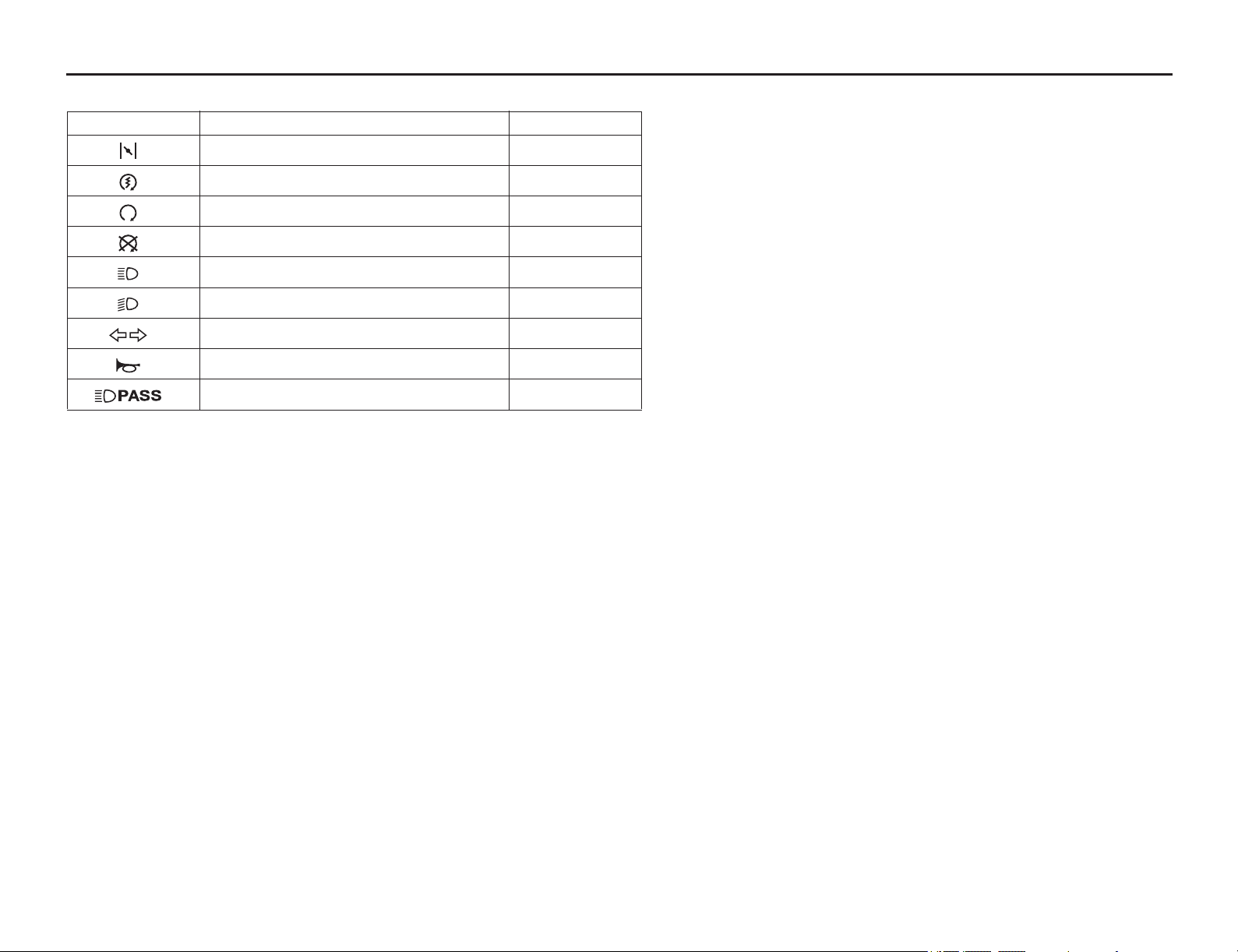
Quick Reference
Quick Reference
These symbols are used in Operating Controls and Basic Operating Instructions sections:
SYMBOL COMPONENT SEE PAGE
fast idle knob 25
START button 15
RUN – engine stop switch 15
STOP – engine stop switch 15
HI – headlight dimmer switch 15
LO – headlight dimmer switch 15
turn signal switch 15
horn button 15
PASS – headlight dimmer switch 15
California Proposition 65 Warning
WARNING
Operating, servicing and maintaining a passenger vehicle or off-highway motor vehicle can expose you
to chemicals including engine exhaust, carbon monoxide, phthalates, and lead, which are known to the
State of California to cause cancer and birth defects or other reproductive harm. To minimize exposure,
avoid breathing exhaust, do not idle the engine except as necessary, service your vehicle in a well-
ventilated area and wear gloves or wash your hands frequently when servicing your vehicle. For more
information go to www.P65Warnings.ca.gov/passenger-vehicle.