
Owner’s Manual
2022
2022
CB500XA


Welcome
●
●
●
2
2
Canada
A Few Words About Safety
●
●
3DANGER
You WILL be KILLED or SERIOUSLY
HURT if you don’t follow instructions.
3WARNING
You CAN be KILLED or SERIOUSLY
HURT if you don’t follow instructions.
3CAUTION
You CAN be HURT if you don’t follow
instructions.
Other important information is
provided under the following titles:
NOTICE

Safety Guidelines.................................................
Safety Labels.........................................................
Safety Precautions...............................................
Riding Precautions ............................................
Accessories & Modifications...........................
Loading ................................................................
This section contains important information for safe riding of your vehicle.
Please read this section carefully.
Vehicle Safety

Safety Guidelines
●
●
●
Always Wear a Helmet
2
Before Riding
Take Time to Learn & Practice
Safety Guidelines
Vehicle Safety
3
Continued

USA
Ride Defensively
Make Yourself Easy to See
Ride within Your Limits
Don't Drink or Use Drugs and Ride
Safety Guidelines
Vehicle Safety
4

Keep Your Honda in Safe Condition
2
2
If You are Involved in a Crash
Safety Guidelines
Vehicle Safety
5
Continued
Carbon Monoxide Hazard
3WARNING
Running the engine of your vehicle
while in an enclosed or even partially
enclosed area can cause a rapid build-
up of toxic carbon monoxide gas.
Breathing this colorless, odorless gas
can quickly cause unconsciousness and
lead to death.
Only run your vehicle's engine when it
is located in a well ventilated area
outdoors.
Safety Guidelines
Vehicle Safety
6
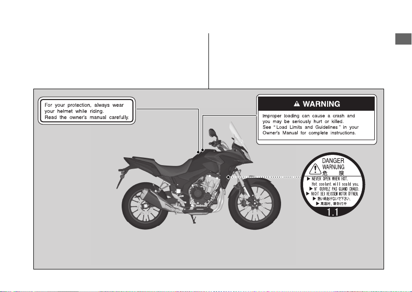
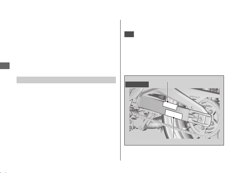
Safety Labels
Safety Labels
Vehicle Safety
7
Continued
Safety Labels
Vehicle Safety
8
Safety Precautions
●
●
●
Protective Apparel
#
Helmet
●
●
USA
3WARNING
Not wearing a helmet increases the
chance of serious injury or death in a
crash.
Make sure that you and any passenger
always wear an approved helmet and
protective apparel.
#
Gloves
Safety Precautions
Vehicle Safety
9
Continued

#
Boots or Riding Shoes
#
Jacket and Pants
Riding Precautions
Break-in Period
●
●
●
Brakes
●
u
u
Riding Precautions
Vehicle Safety
10

●
u
●
u
●
#
Anti-lock Brake System (ABS)
●
●
●
●
Riding Precautions
Vehicle Safety
11
Continued

#
Engine Braking
#
Wet or Rainy Conditions
Parking
●
●
●
●
●
#
Parking with the Side Stand
1.
2.
Riding Precautions
Vehicle Safety
12

3.
4.
u
5.
2
Refueling and Fuel Guidelines
●
●
●
2
●
●
Riding Precautions
Vehicle Safety
13

Accessories &
Modifications
3WARNING
Improper accessories or modifications
can cause a crash in which you can be
seriously hurt or killed.
Follow all instructions in this owner's
manual regarding accessories and
modifications.
Accessories & Modifications
Vehicle Safety
14

Loading
●
●
Maximum weight capacity 2
●
●
3WARNING
Overloading or improper loading can
cause a crash and you can be seriously
hurt or killed.
Follow all load limits and other loading
guidelines in this manual.
Loading
Vehicle Safety
15
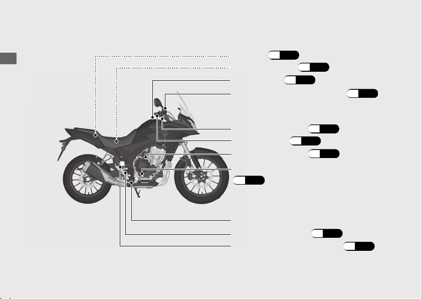
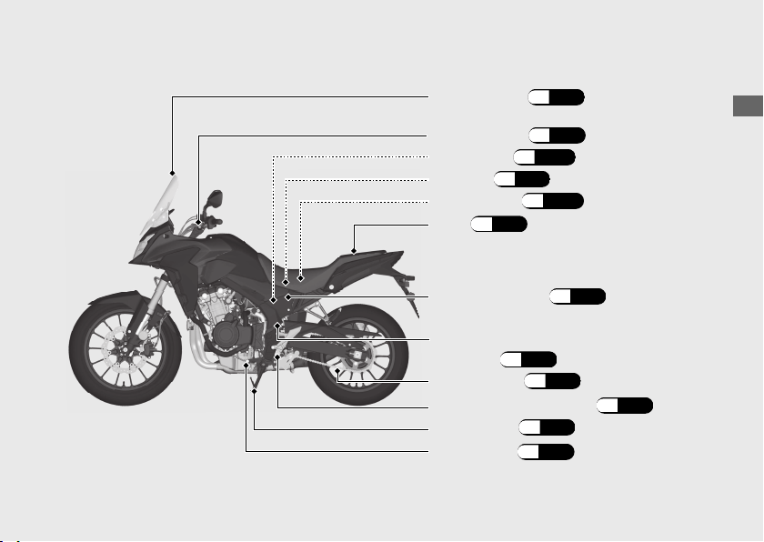
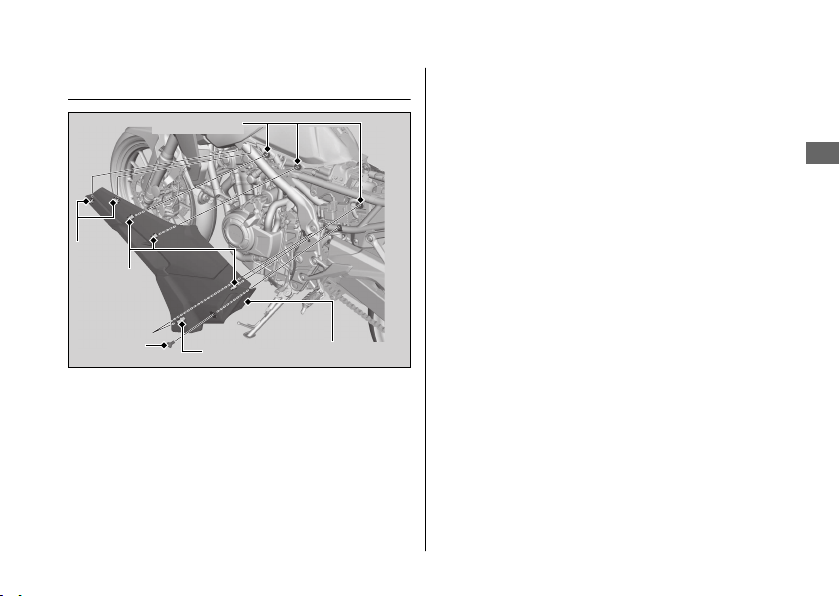
Parts Location
Operation Guide
16
Front brake lever
(P.93)
Throttle grip(P.92)
Rear brake fluid reservoir
(P.84)
Rear brake pedal
Engine oil fill cap
(P.80)
Engine oil level inspection window
(P.80)
Tool kit(P.56)
Document bag(P.56)
Front brake fluid reservoir(P.84)
Fuel fill cap(P.54)
Brake light switch
(P.86)
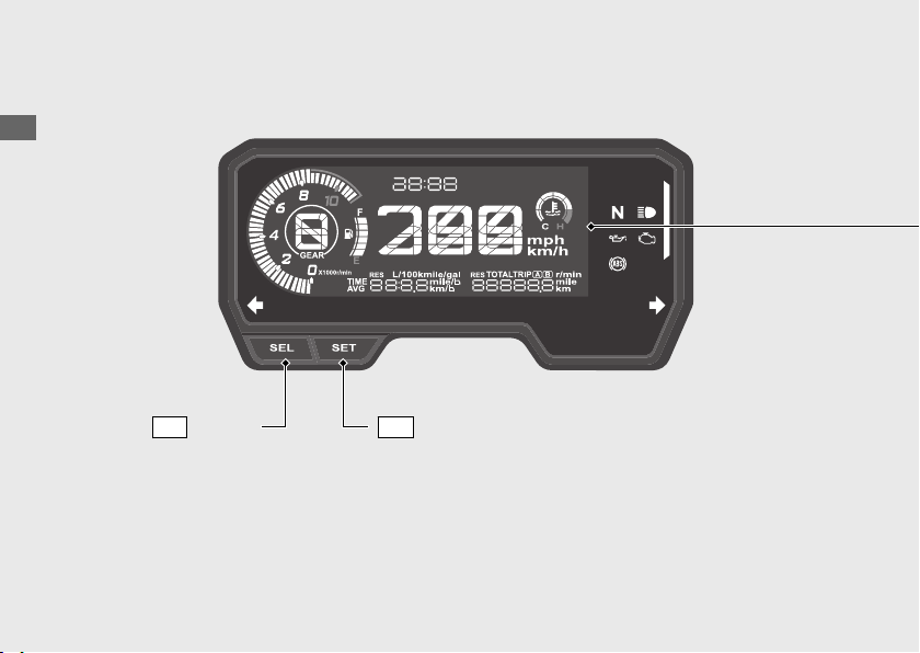
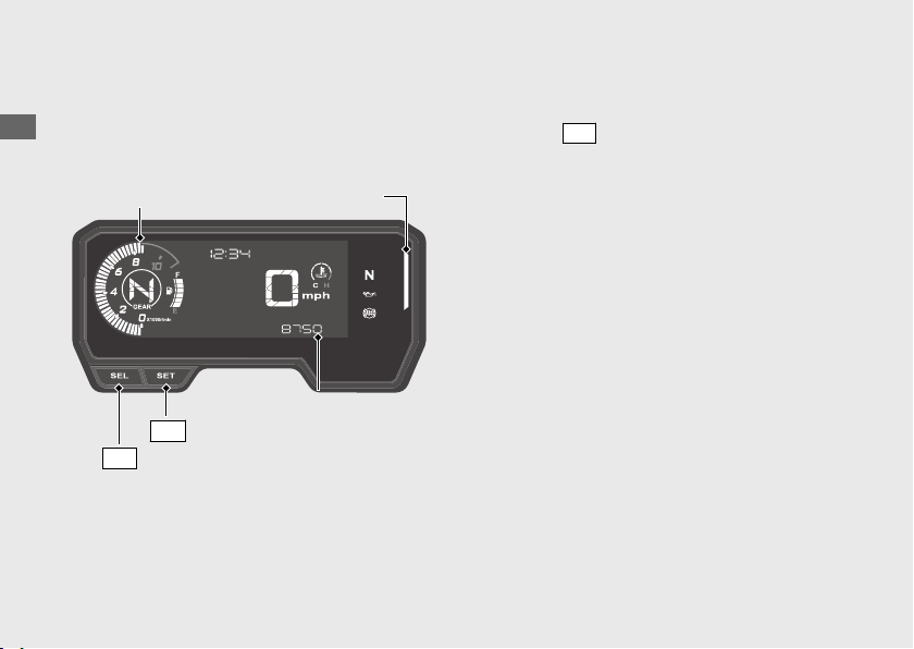
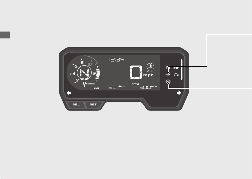
Instruments
Operation Guide
18
Display Check
SEL
button
SET
button
Operation Guide
19
Continued
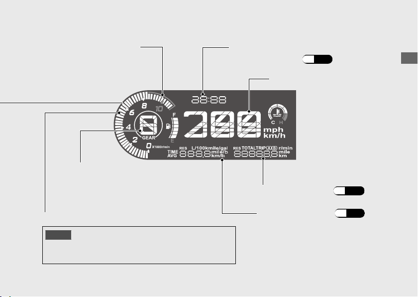
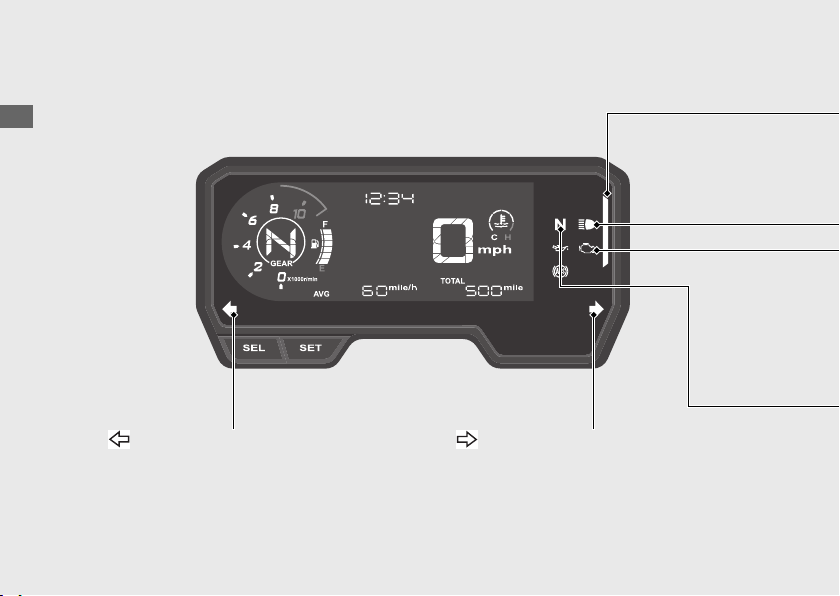
Speedometer
Tachometer red zone
NOTICE
Tachometer
To set the clock:
(P.31)
Clock (12-hour or 24-hour display)
Section A display
(P.21)
Section B display
(P.25)
u
Gear position indicator
Operation Guide
20
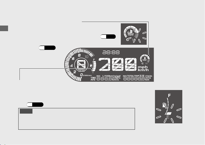
Instruments (Continued)
If the segment H flashes while riding:
(P.99)
If the coolant temperature gauge indicator
flashes: (P.103)
Coolant temperature gauge
Fuel gauge
If the fuel gauge indicator flashes in a repeat pattern or turns
off:
(P.102)
NOTICE
#
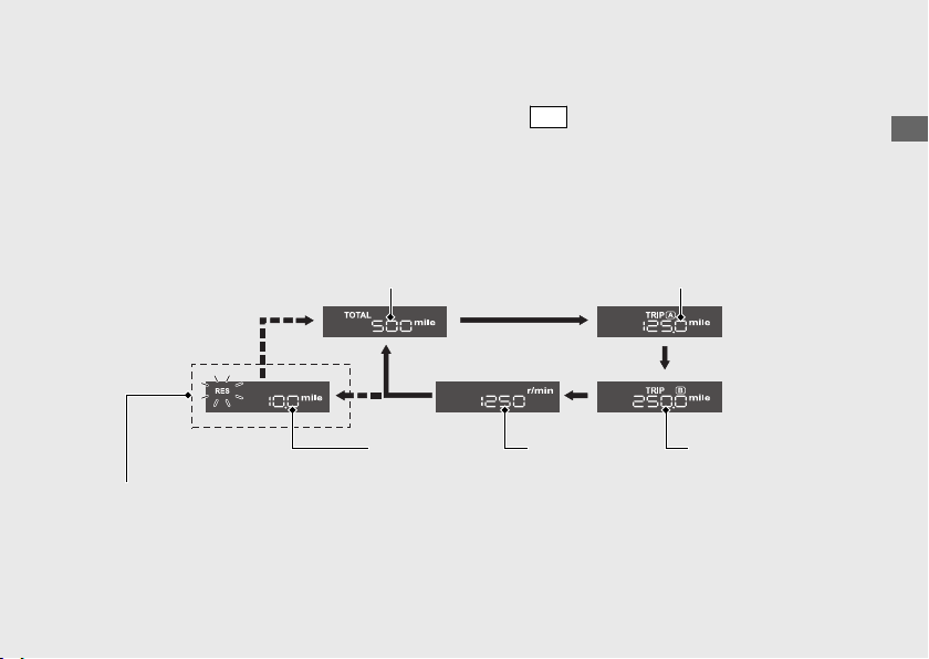
Section A display
●
●
●
●
●
●
#
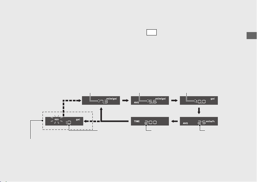
Changing the section A display
SEL
Operation Guide
21
Continued
When the 1st (E) segment of
the fuel gauge starts flashing
Current fuel
mileage
Average fuel
mileage
Fuel
consumption
Average
speed
Reserve fuel
consumption
Elapsed
time

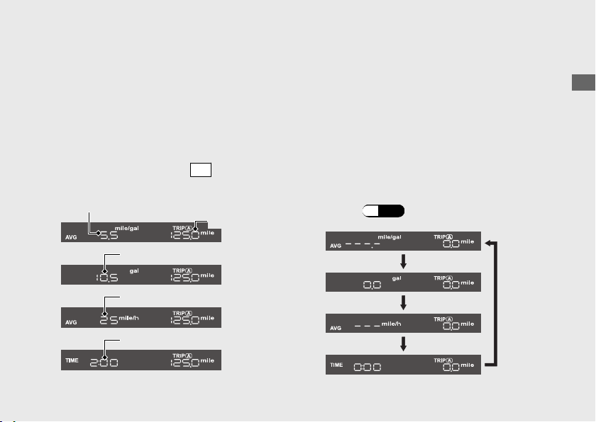
#
Current fuel mileage
•
•
#
Average fuel mileage [AVG]
•
•
To reset the average fuel mileage:
(P.27)
Operation Guide
22
Instruments (Continued)

#
Fuel consumption
•
To reset the fuel consumption:
(P.27)
#
Average speed [AVG]
•
•
•
Operation Guide
23
Continued

To reset the average speed:(P.27)
#
Elapsed time [TIME]
●
To reset the elapsed time:
(P.27)
#
Reserve fuel consumption [RES]
●
u
Operation Guide
24
Instruments (Continued)
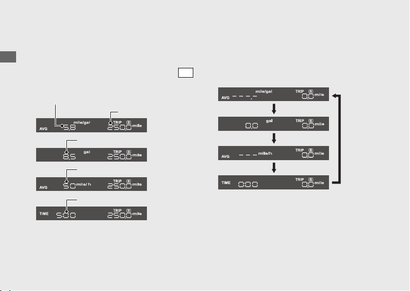
#
Section B display
●
●
●
●
#
Changing the section B display
SET
Operation Guide
25
Continued
When the 1st (E) segment of
the fuel gauge starts flashing
Odometer Tripmeter A
Reserve
tripmeter
Numerical
tachometer
Tripmeter B

#
Odometer [TOTAL]
#
Tripmeter [TRIP A/B]
To reset the tripmeter:(P.27)
#
Numerical tachometer
#
Reserve tripmeter [RES]
Operation Guide
26
Instruments (Continued)
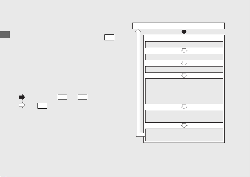
#
To reset the tripmeter [TRIP A/B],
average fuel mileage [AVG], fuel
consumption, average speed [AVG]
and elapsed time
SET
(P.33)
Operation Guide
27
Continued
Tripmeter A
Fuel consumption A
Elapsed time A
Average speed A
Average fuel mileage A
SET
Operation Guide
28
Instruments (Continued)
Tripmeter B
Fuel consumption B
Elapsed time B
Average speed B
Average fuel mileage B

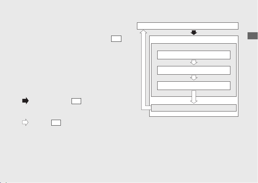
Display Setting
Setting Mode A
(P.30)
•
•
•
•
•
•
Setting Mode B
(P.35)
•
-
-
-
•
Operation Guide
29
Continued
Setting Mode A
SET
Operation Guide
30
Instruments (Continued)
SEL
SET
SET
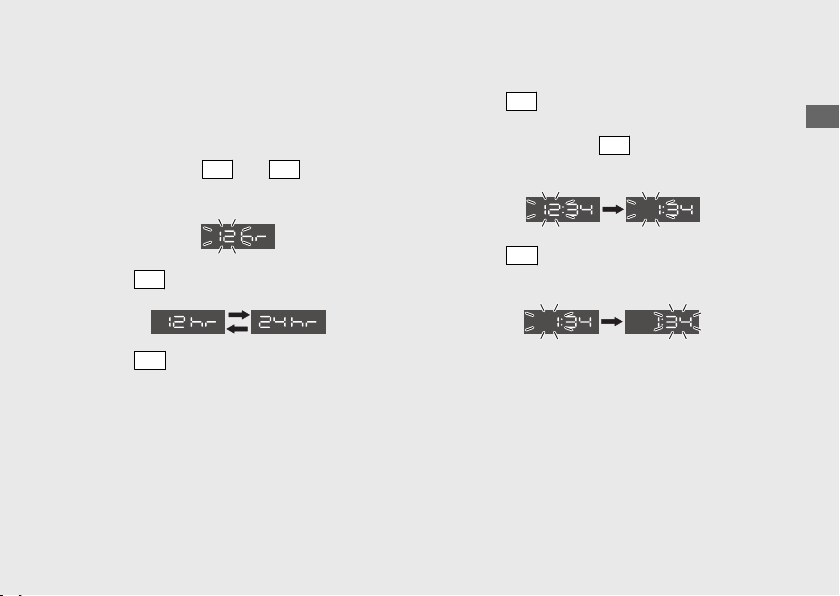
1 Time format setting:
a
b
SEL
SET
c
SEL
d
SET
2 Clock setting:
a
SEL
u
SEL
b
SET
Operation Guide
31
Continued
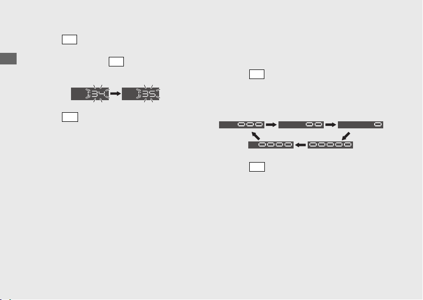
c
SEL
u
SEL
d
SET
3 Backlight brightness adjustment:
a
SEL
u
b
SET
Operation Guide
32
Instruments (Continued)
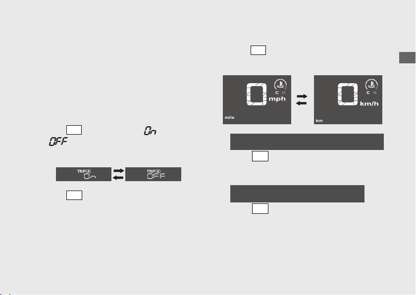
4 Activating/deactivating of tripmeter
A, average fuel mileage, fuel
consumption, average speed and
elapsed time automatic reset mode:
a
SEL
b
SET
5 Changing of speed and mileage unit:
a
SEL
b
When “km/h” for speed and “km” for mileage
are selected
SET
When “mph” for speed and “mile” for
mileage are selected
SET
Operation Guide
33
Continued

6 Changing the fuel mileage meter unit:
a
SEL
b
SET
Operation Guide
34
Instruments (Continued)
Setting Mode B
SET
Operation Guide
35
Continued
SEL
SET
1 Setting of REV indicator:
a
SEL
u
Operation Guide
36
Instruments (Continued)
SET
button
SEL
button
Tachometer
REV indicator
Numerical
tachometer
b
SEL
u
SEL
Operation Guide
37
Continued
Numerical
tachometer
Tachometer
c
SET
d
SEL
Operation Guide
38
Instruments (Continued)
Tachometer
Numerical tachometer
e
SET
f
SEL
u
g
SET
Operation Guide
39
Continued
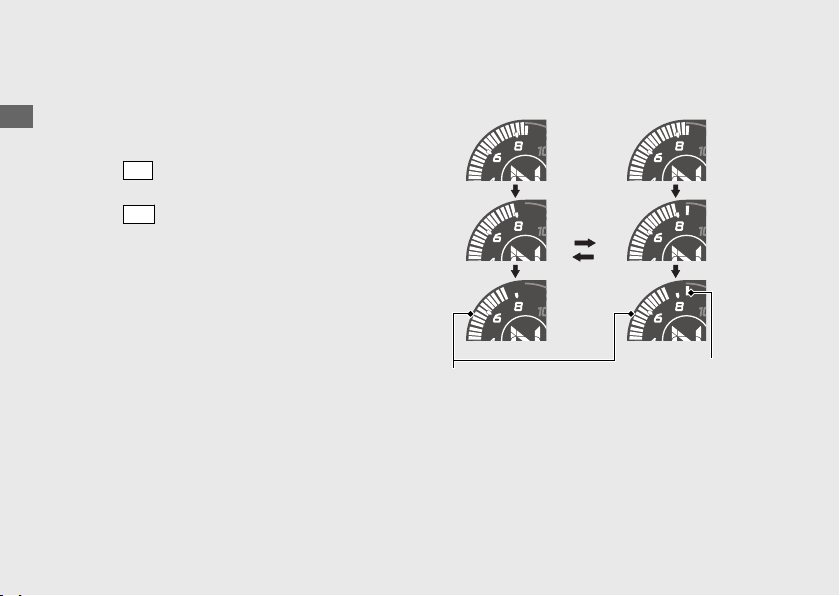
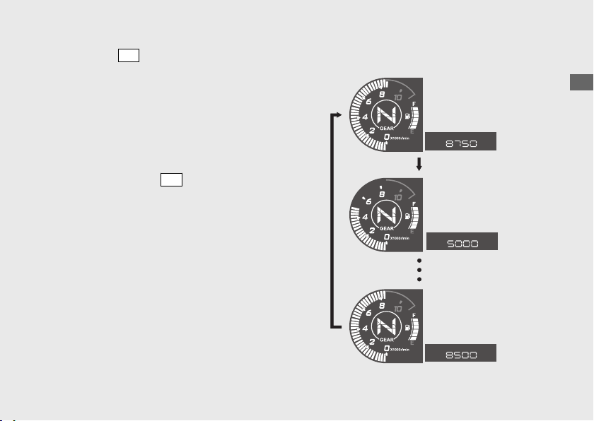
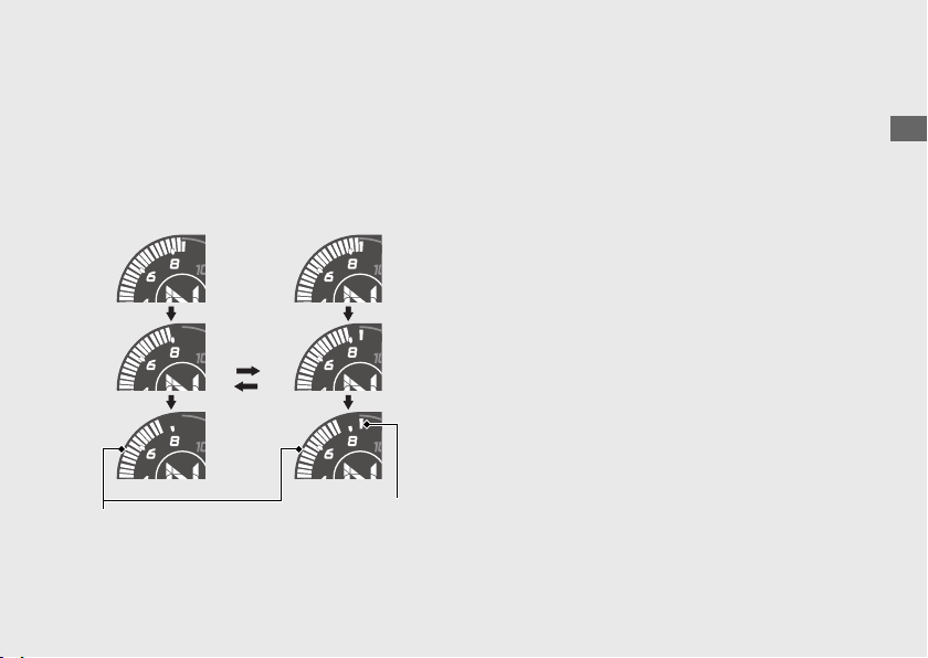
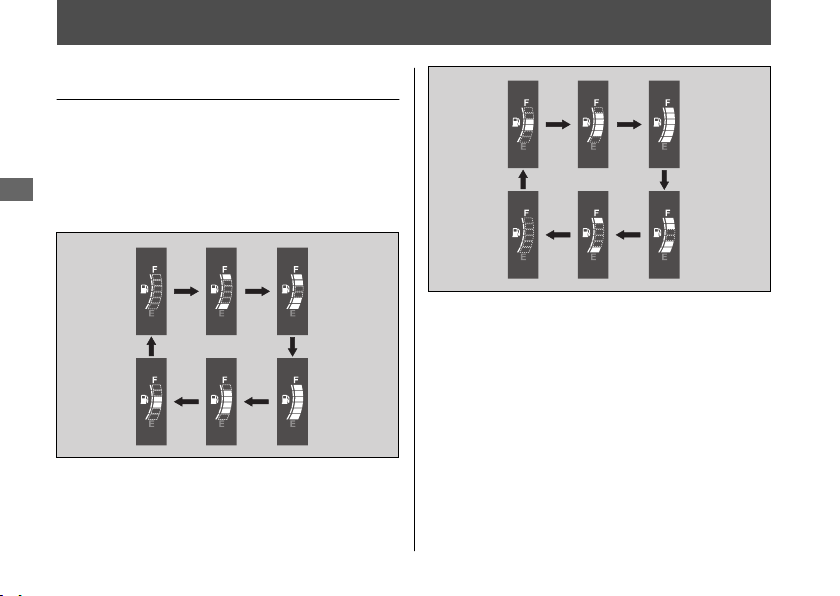
2 Changing of tachometer display
mode:
a
SEL
b
SET
Conventionaldisplay
Peak hold display
Operation Guide
40
Instruments (Continued)
Conventional
display
Peak
hold
segment
Peak hold
display
Tachometer
bar segment
Operation Guide
41
Conventional
display
Peak
hold
segment
Peak hold
display
Tachometer
bar segment
Indicators
Operation Guide
42
Right turn signal indicatorLeft turn signal indicator
Operation Guide
43
Continued
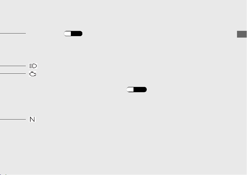
High beam indicator
Neutral indicator
REV indicator
(P.46)
PGM-FI (Programmed FuelInjection) malfunction indicator lamp (MIL)
If it comes on while engine is running:(P.100)
Operation Guide
44
Indicators (Continued)
Operation Guide
45
Continued
●
●
If it comes on while engine is running:
(P.100)
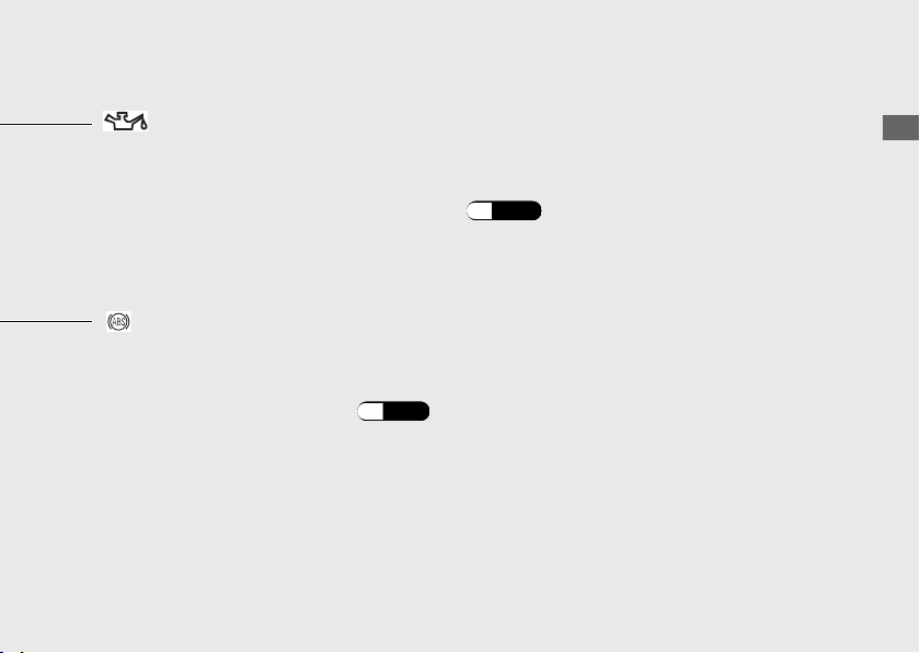
Low oil pressure indicator
●
●
ABS (Anti-lock Brake System) indicator
If it comes on while riding: (P.101)
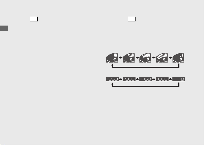
REV Indicator
●
Initial setting
To set the shift up rev setting:
(P.36)
To set the shift width setting: (P.38)
Operation Guide
46
Indicators (Continued)

Operation Guide
47
This page intentionally left blank.
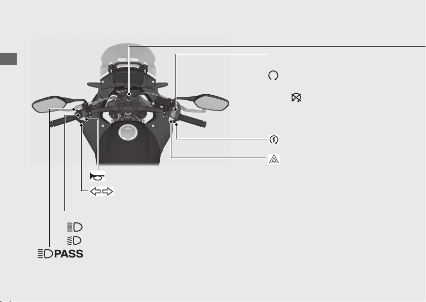
Switches
Operation Guide
48
Headlight dimmer switch
•
•
Turn signal switch
Horn button
u
Engine stop switch
u
Start button
Hazard switch
Passing light control switch
Operation Guide
49
Continued
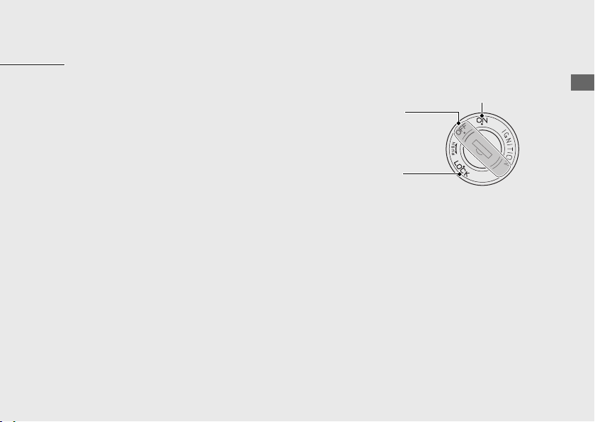
Ignition Switch
u
ON
OFF
LOCK
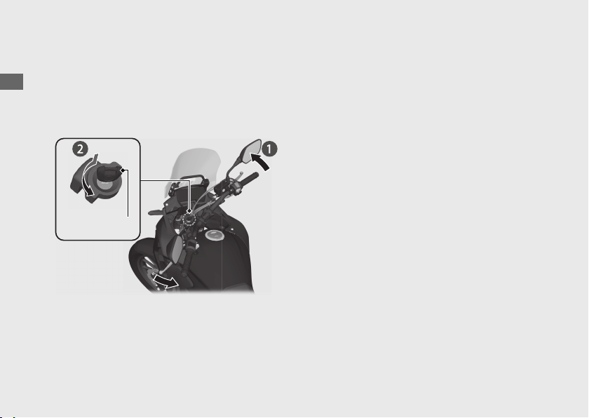
Steering Lock
#
Locking
a
b
u
c
#
Unlocking
Operation Guide
50
Switches (Continued)
Ignition key
Push
Turn
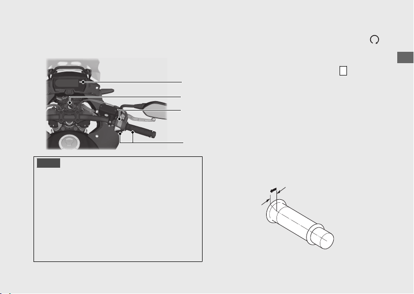
Starting the Engine
NOTICE
•
•
•
•
a
b
c
d
u
Operation Guide
51
Continued
a
b
c
d
About 1/8 in (3 mm), without freeplay

If the engine does not start:
a
b
c
d
ab
#
If Engine Will Not Start (P.98)
Operation Guide
52
Starting the Engine (Continued)
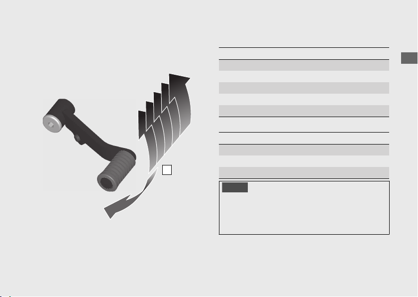
Shifting Gears
#
Recommended Shift Points
Shifting Up
Shifting Down
NOTICE
Operation Guide
53
2
3
4
5
6
1
N
Refueling
Fuel type:
Recommended fuel octane number:
Tank capacity:
#
Refueling and Fuel Guidelines (P.13)
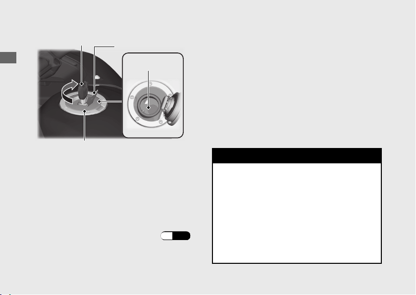
Opening the Fuel Fill Cap
Closing the Fuel Fill Cap
a
b
u
3WARNING
Gasoline is highly flammable and
explosive. You can be burned or
seriously injured when handling fuel.
• Stop the engine, and keep heat,
sparks, and flames away.
• Only handle fuel outdoors.
• Wipe up spills immediately.
Operation Guide
54
Ignition key
Level plate
Fuel fill cap
Lock cover
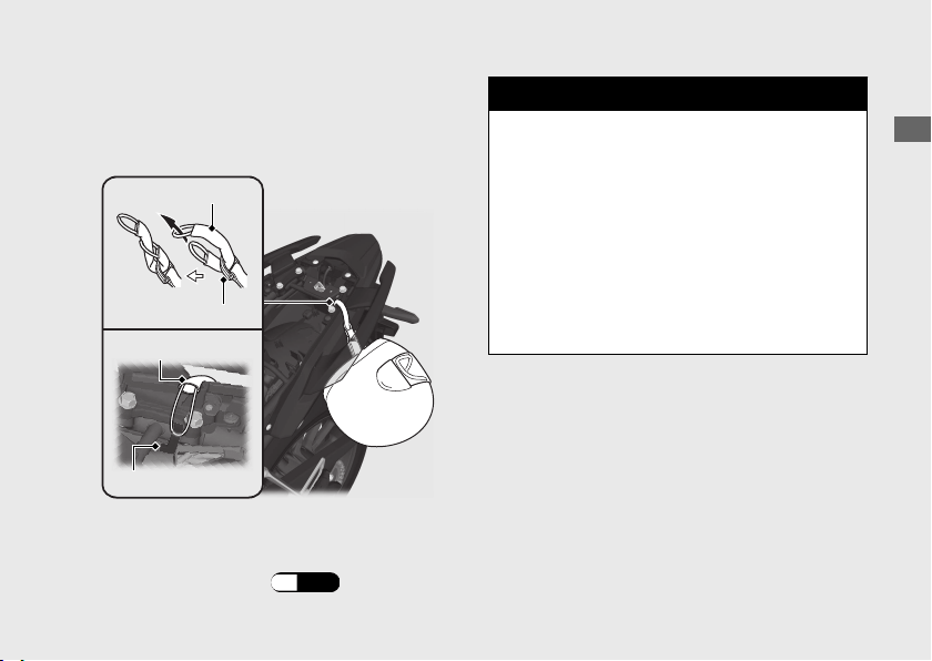
Storage Equipment
Helmet Holder
u
#
Removing the Seat (P.78)
3WARNING
Riding with a helmet attached to the
holder can interfere with the rear wheel
or suspension and could cause a crash
in which you can be seriously hurt or
killed.
Use the helmet holder only while
parked. Do not ride with a helmet
secured by the holder.
Operation Guide
55
Continued
Helmet holder
Helmet D-ring
Helmet set wire
Helmet set wire

Importance of Maintenance ...........................
Maintenance Schedule.....................................
Maintenance Record.........................................
Maintenance Fundamentals ...........................
Removing & Installing Body Components..
Engine Oil ............................................................
Coolant.................................................................
Brakes...................................................................
Side Stand ...........................................................
Drive Chain..........................................................
Clutch ...................................................................
Throttle ................................................................
Other Adjustments............................................
Please read “Importance of Maintenance” and “Maintenance Fundamentals” carefully
before attempting any maintenance. Refer to “Specifications” for service data.
An optional larger tool kit may be available.
Check with your Honda dealer's parts department.
Maintenance
Importance of Maintenance
Importance of Maintenance
2
3WARNING
Improperly maintaining your vehicle or
failing to correct a problem before you
ride can cause a crash in which you can
be seriously hurt or killed.
Always follow the inspection and
maintenance recommendations and
schedules in this owner's manual.
2
USA
Maintenance, replacement or repair of the
emission control devices and systems may
be performed by any vehicle repair
establishment or individual using parts
that are certified to EPA standards.
Maintenance
58

Maintenance Safety
●
●
●
●
Importance of Maintenance
Maintenance
59

Maintenance Schedule
2
Maintenance
60
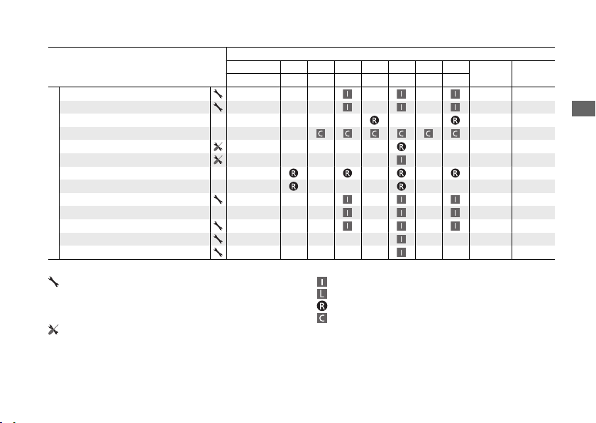
Items
Frequency
*1
× 1,000 mi 0.6 4 8 12 16 20 24
Regular
Replace
Refer to
page
× 1,000 km 1.0 6.4 12.8 19.2 25.6 32.0 38.4
Emission-Related Items
Fuel Line –
Throttle Operation 92
Air Cleaner
*2
–
Crankcase Breather
*3
–
Spark Plug –
Valve Clearance –
Engine Oil 1 Year –
Engine Oil Filter –
Engine Idle Speed –
Radiator Coolant
*5
3 Years 82
Cooling System –
Secondary Air Supply System –
Evaporative Emission Control System
*4
–
Maintenance Level Maintenance Legend
2
Maintenance Schedule
Maintenance
61
Continued
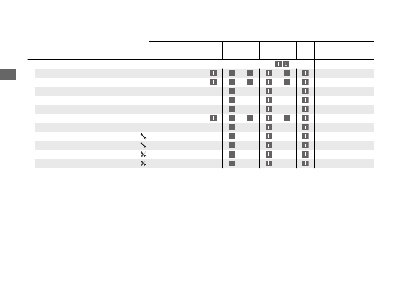
Items
Frequency
*1
× 1,000 mi 0.6 4 8 12 16 20 24
Regular
Replace
Refer to
page
× 1,000 km 1.0 6.4 12.8 19.2 25.6 32.0 38.4
Non-Emission-Related Items
Drive Chain
Every 600 mi (1,000 km):
88
Brake Fluid
*5
2 Years 84
Brake Pads Wear 85
Brake System 64
Brake Light Switch 86
Headlight Aim –
Clutch System 89
Side Stand 87
Suspension –
Nuts, Bolts, Fasteners –
Wheels/Tires 73
Steering Head Bearings –
Notes:
Maintenance Schedule
Maintenance
62
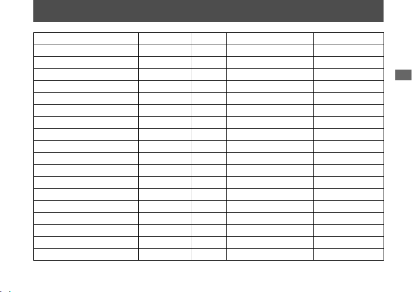
Maintenance Record
Distance Odometer Date Performed By: Notes
Maintenance
63

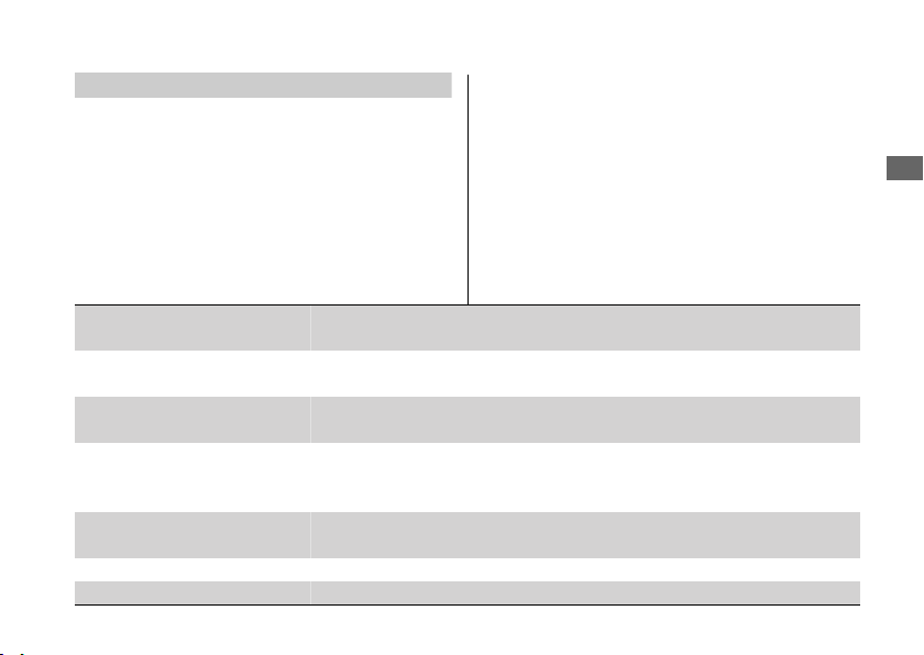
Maintenance Fundamentals
Pre-ride Inspection
●
2
●
●
2
●
2
●
● 2
●
2
●
●
2 2
●
2
●
2
●
2
2
●
2
● 2
Maintenance
64
2
2
2 2
2
2
2 2
2 2
Periodic Checks
2
Maintenance Fundamentals
Maintenance
65
Replacing Parts
2
3WARNING
Installing non-Honda parts may make
your vehicle unsafe and cause a crash in
which you can be seriously hurt or
killed.
Always use Honda Genuine Parts or
equivalents that have been designed
and approved for your vehicle.
Maintenance Fundamentals
Maintenance
66
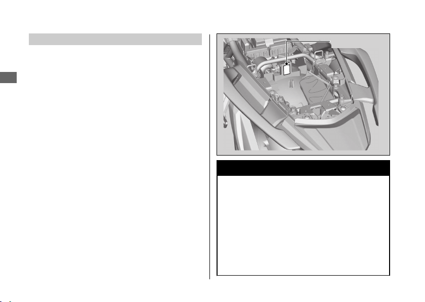
Color label
Battery
NOTICE
#
What to do in an emergency
●
u
●
u
●
u
3WARNING
The battery gives off explosive hydrogen gas
during normal operation.
A spark or flame can cause the battery to explode
with enough force to kill or seriously hurt you.
Wear protective clothing and a face shield, or
have a skilled mechanic do the battery servicing.
WARNING:
Wash your hands after handling.
Maintenance Fundamentals
Maintenance
67
Continued
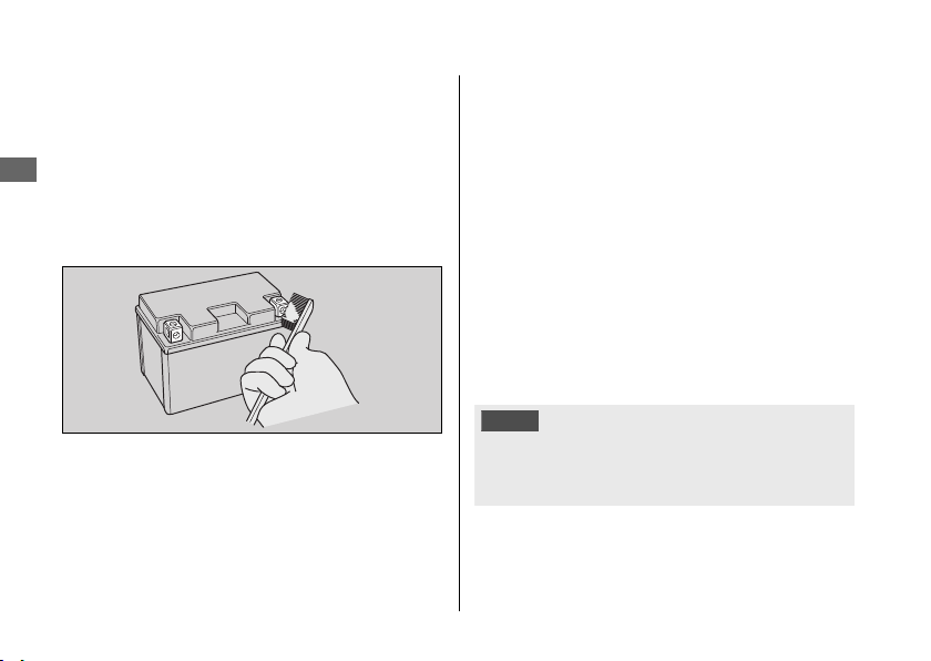
#
Cleaning the Battery Terminals
1.
2
2.
3.
4.
#
Charging
NOTICE
Maintenance Fundamentals
Maintenance
68
NOTICE
NOTICE
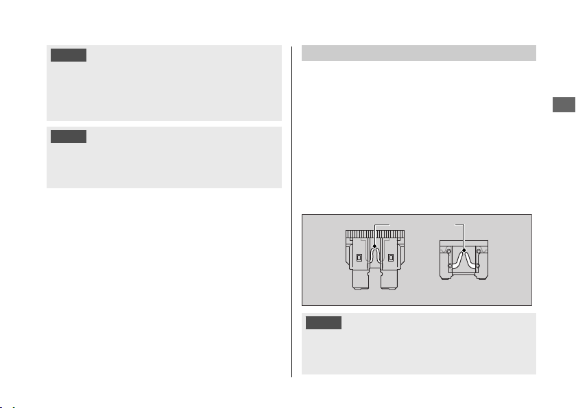
Fuses
2
#
Inspecting and Replacing Fuses
2
NOTICE
Maintenance Fundamentals
Maintenance
69
Continued
Blown fuse
Engine Oil
#
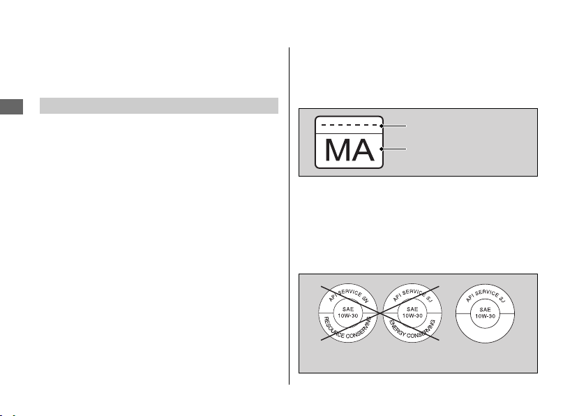
Selecting the Engine Oil
2
●
●
●
Maintenance Fundamentals
Maintenance
70
Oil code
Oil classification
Not recommended Recommended
Brake Fluid
NOTICE
Recommended brake fluid:
3WARNING
Clean filler cap before removing. Use
only DOT 4 fluid from a sealed
container.
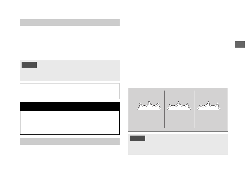
Drive Chain
2
NOTICE
Maintenance Fundamentals
Maintenance
71
Continued
Normal
(GOOD)
Worn
(REPLACE)
Damaged
(REPLACE)
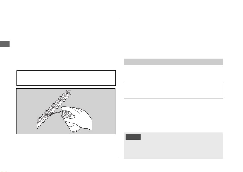
#
Cleaning and Lubricating
Recommended lubricant:
Recommended Coolant
Concentration:
NOTICE
Maintenance Fundamentals
Maintenance
72
Crankcase Breather
Tires (Inspecting/Replacing)
#
Checking the Air Pressure
#
Inspecting for Damage
Maintenance Fundamentals
Maintenance
73
Continued
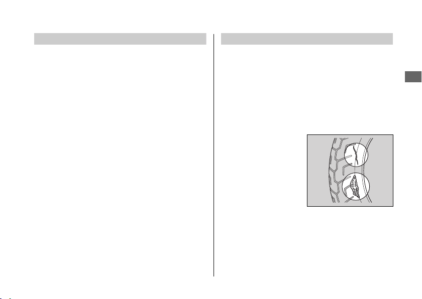
#
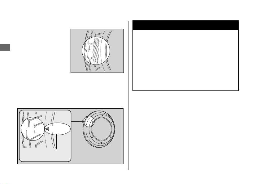
Inspecting for Abnormal Wear
#
Inspecting Tread Depth
3WARNING
Riding on tires that are excessively worn
or improperly inflated can cause a crash
in which you can be seriously hurt or
killed.
Follow all instructions in this owner's
manual regarding tire inflation and
maintenance.
Maintenance Fundamentals
Maintenance
74
Wear indicator
location mark
or TWI

2
●
●
●
●
3WARNING
Installing improper tires on your vehicle
can adversely affect handling and
stability, and can cause a crash in which
you can be seriously hurt or killed.
Always use the size and type of tires
recommended in this owner's manual.
Maintenance Fundamentals
Maintenance
75
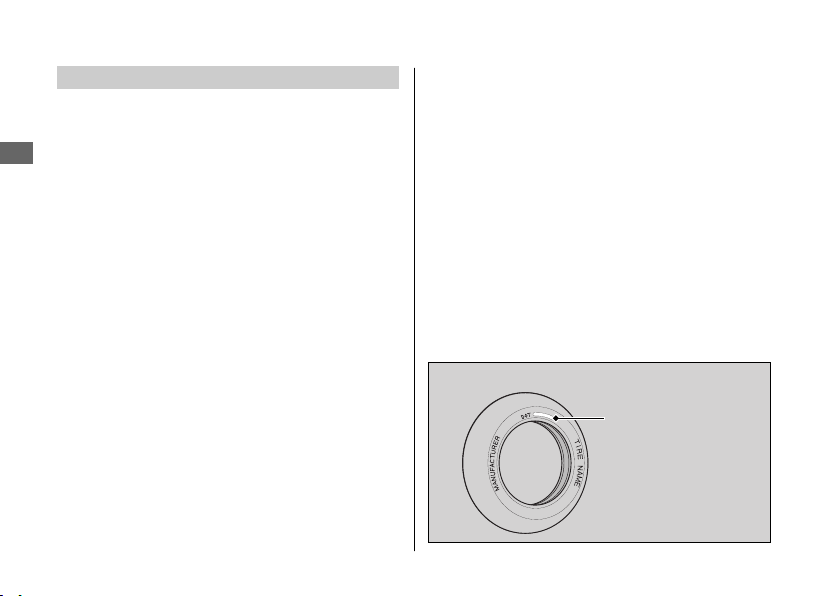
Tire Service Life
#
Tire Identification Number (TIN)
a b c
DOT XXXX XXXX 22 09
a
b
c
Maintenance Fundamentals
Maintenance
76
Tire Labeling Example
Tire identification
number (TIN)
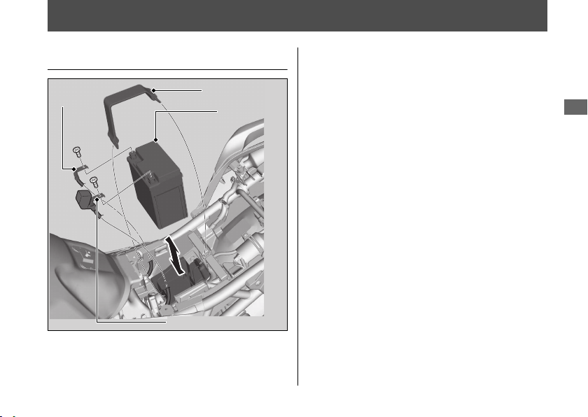
Removing & Installing Body Components
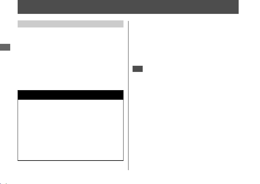
Battery
#
Removal
1.
2
2.
3.
-
4.
+
5.
#
Installation
+
2
2
2
Maintenance
77
Rubber strap
Positive terminal
Negative
terminal
Battery
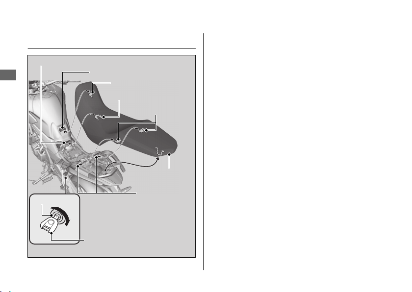
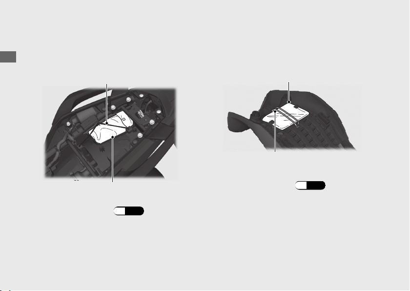
Seat
#
Removal
1.
2.
#
Installation
1.
2.
Removing & Installing Body Components u Seat
Maintenance
78
Ignition key
Seat lock
Tab
Recess
Front prong
Rear prongs
Seat
Rear stays
Front stay
Left Side Cover
#
Removal
1.
2
2.
3.
#
Installation
Removing & Installing Body Components u Left Side Cover
Maintenance
79
Left side cover
Bolt
Grommets
Prongs
Hooks
Hook
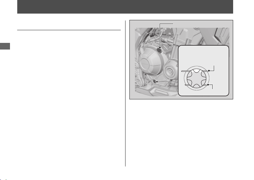
Engine Oil
Checking the Engine Oil
1.
2.
3.
4.
Maintenance
80
Oil fill cap
Oil level inspection
window
Upper level
Lower level
Adding Engine Oil
2 2
1.
u
u
u
u
2.
NOTICE
2
Engine Oil u Adding Engine Oil
Maintenance
81
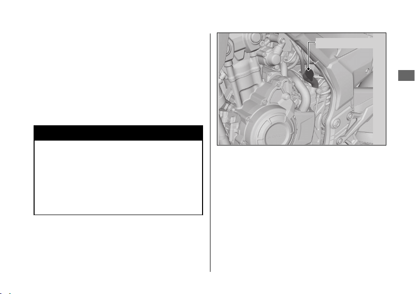
Coolant
Checking the Coolant
1.
2.
3.
Adding Coolant
2
Maintenance
82
UPPER level
mark
LOWER level
mark
Reserve tank
1.
u
u
2.
3WARNING
Removing the radiator cap while the
engine is hot can cause the coolant to
spray out, potentially scalding you.
Always let the engine and radiator cool
down before removing the radiator cap.
Coolant u Adding Coolant
Maintenance
83
Reserve tank cap
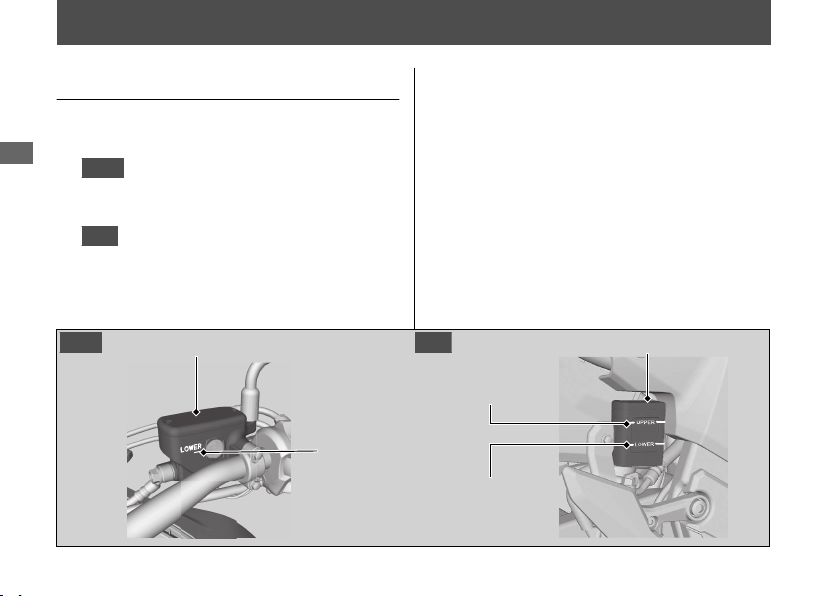
Brakes
Checking Brake Fluid
1.
2.
Front
Rear
Maintenance
84
Front brake fluid reservoir
LOWER level
mark
UPPER level
mark
LOWER level
mark
Rear brake fluid reservoir
Front Rear
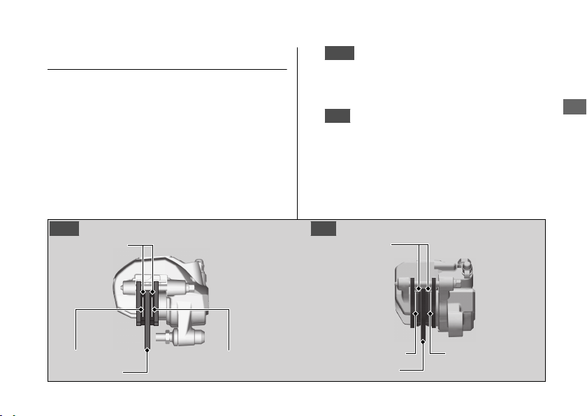
Inspecting the Brake Pads
1.
Front
u
2.
Rear
Brakes u Inspecting the Brake Pads
Maintenance
85
Front Rear
Pads
Disc
Wear indicator
Pads
Wear indicator
Disc
Wear indicator
Wear indicator
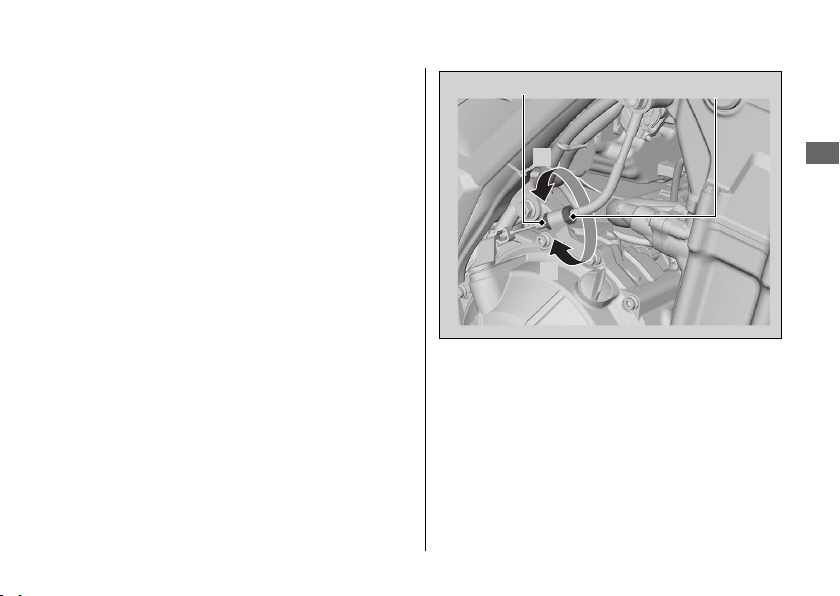
Adjusting the Brake Light
Switch
Brakes u Adjusting the Brake Light Switch
Maintenance
86
Brake light switch
Adjusting nut
B
A
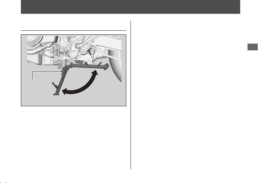
Side Stand
Checking the Side Stand
1.
2.
3.
4.
5.
Maintenance
87
Side stand
spring
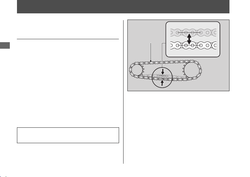
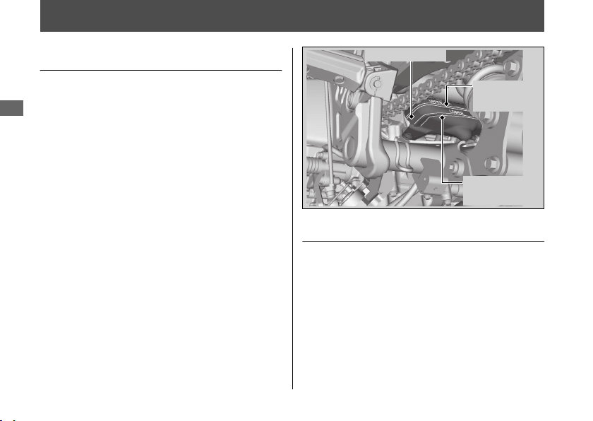
Drive Chain
Inspecting the Drive Chain
Slack
1.
2.
3.
Drive chain slack:
u
4.
5.
2
6.
2
Maintenance
88
Drive chain
Clutch
Checking the Clutch
#
Checking the Clutch Lever Freeplay
Freeplay at the clutch lever:
NOTICE
Maintenance
89
Clutch lever
Freeplay
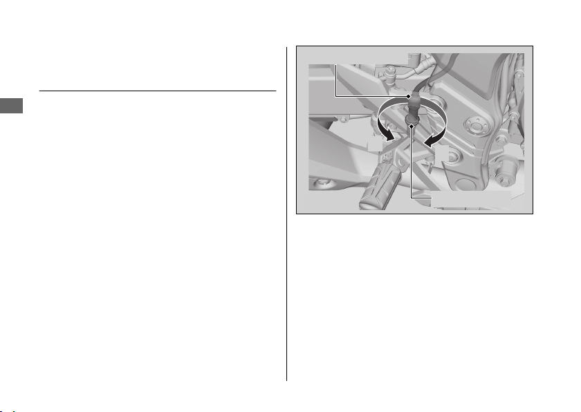
Adjusting the Clutch Lever
Freeplay
#
Upper Adjustment
1.
2.
3.
#
Lower Adjustment
Clutch u Adjusting the Clutch Lever Freeplay
Maintenance
90
Upper lock nut
Upper clutch cable adjuster
+
–
1.
2.
3.
4.
5.
Clutch u Adjusting the Clutch Lever Freeplay
Maintenance
91
Lower lock nut Adjusting nut
+
–
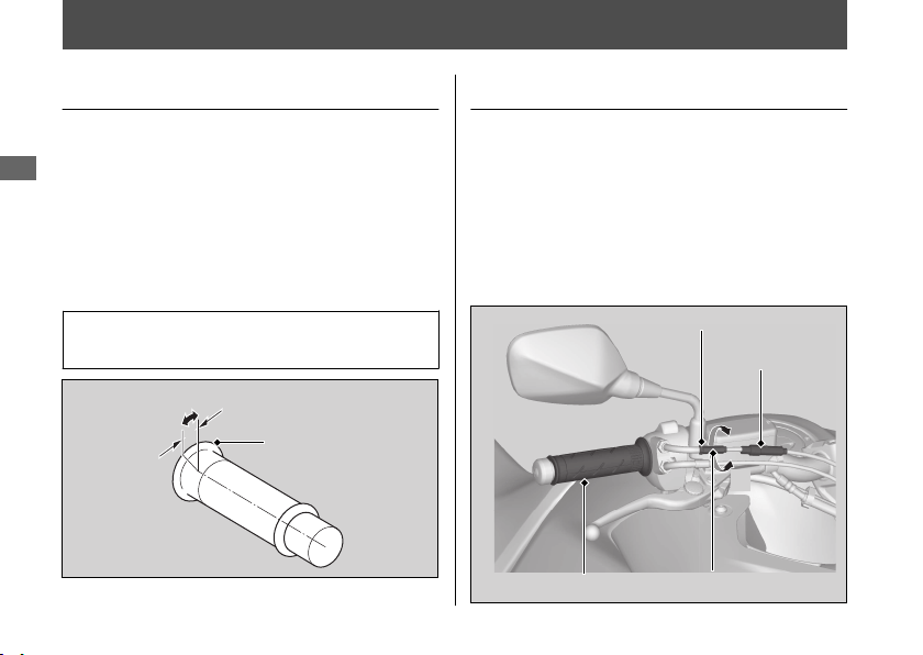
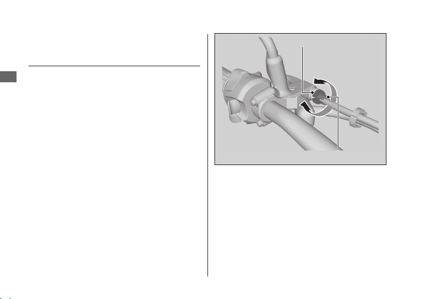
Throttle
Checking the Throttle
Freeplay at the throttle grip flange:
Adjusting the Throttle Freeplay
1.
2.
3.
4.
Maintenance
92
Freeplay
Flange
Lock nut
Cable boot
Throttle grip
Adjuster
–
+
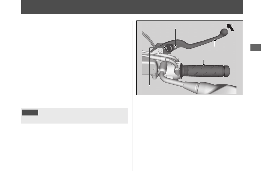
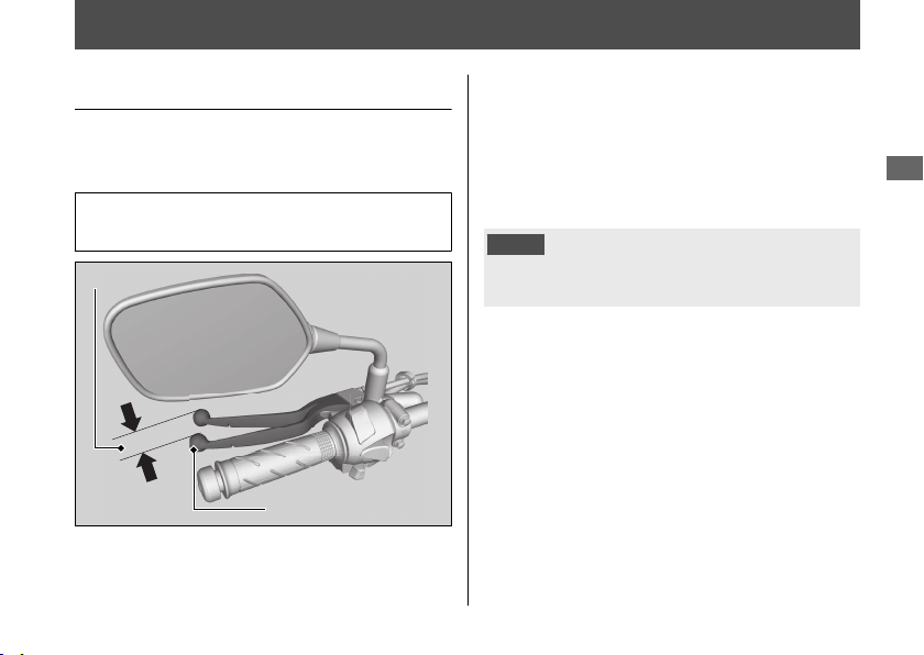
Other Adjustments
Adjusting the Brake Lever
#
Adjustment method
NOTICE
Maintenance
93
Index mark
Adjuster
Forward
Brake lever
Handle grip
Adjusting the Rear Suspension
#
Spring Preload
NOTICE
NOTICE
NOTICE
Other Adjustments u Adjusting the Rear Suspension
Maintenance
94
Adjuster
1234 5
Pin spanner
Extension bar
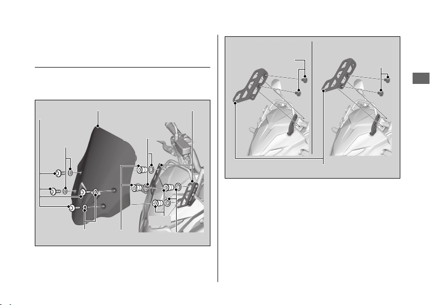
Adjusting the Windscreen
Height
1.
2.
3.
4.
Other Adjustments u Adjusting the Windscreen Height
Maintenance
95
Continued
Windscreen
Washers B
Bolts A
Washers A
Nuts
Nuts
Windscreen
stays
Washers A
Washers B
High positionLow position
Bolts B
Bolts B
Windscreen stay

5.
u
6.
7.
Other Adjustments u Adjusting the Windscreen Height
Maintenance
96

Engine Will Not Start........................................
Overheating (Segment H flashes in coolant
temperature gauge) .......................................
Warning Indicators On or Flashing.............
Other Warning Indications ...........................
Tire Puncture ....................................................
Electrical Trouble.............................................
Troubleshooting

Engine Will Not Start
Starter Motor Operates But
Engine Does Not Start
●
2
●
●
u
Starter Motor Does Not
Operate
●
2
●
2
● 2
●
2
2
●
2
Troubleshooting
98

Overheating (Segment H flashes in coolant temperature gauge)
●
●
NOTICE
1.
2.
If the fan is not operating:
If the fan is operating:
3.
2
If there is a leak:
4.
2
u
5.
Troubleshooting
99
Warning Indicators On or Flashing
Low Oil Pressure Indicator
NOTICE
1.
2 2
2.
u
PGM-FI (Programmed Fuel
Injection) Malfunction
Indicator Lamp (MIL)
Troubleshooting
100

ABS (Anti-lock Brake System)
Indicator
●
●
●
Warning Indicators On or Flashing u ABS (Anti-lock Brake System) Indicator
Troubleshooting
101
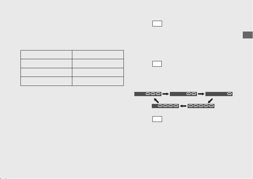
Other Warning Indications
Fuel Gauge Failure Indication
Troubleshooting
102
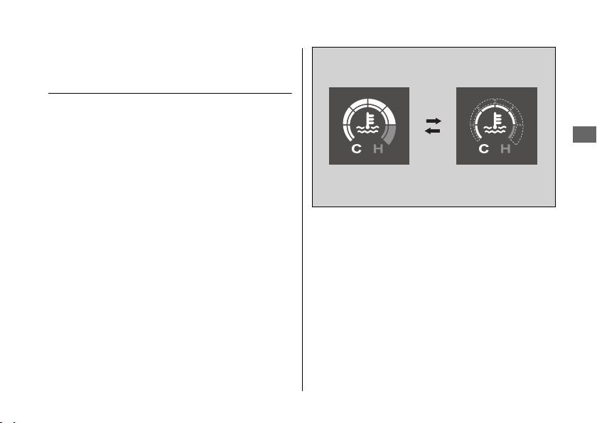
Coolant Temperature Gauge
Failure Indication
Other Warning Indications u Coolant Temperature Gauge Failure Indication
Troubleshooting
103

Tire Puncture
Emergency Repair Using a Tire
Repair Kit
3WARNING
Riding your vehicle with a temporary
tire repair can be risky. If the temporary
repair fails, you can crash and be
seriously injured or killed.
If you must ride with a temporary tire
repair, ride slowly and carefully and do
not exceed 30 mph (50 km/h) until the
tire is replaced.
Troubleshooting
104
Electrical Trouble
Battery Goes Dead
NOTICE
Troubleshooting
105
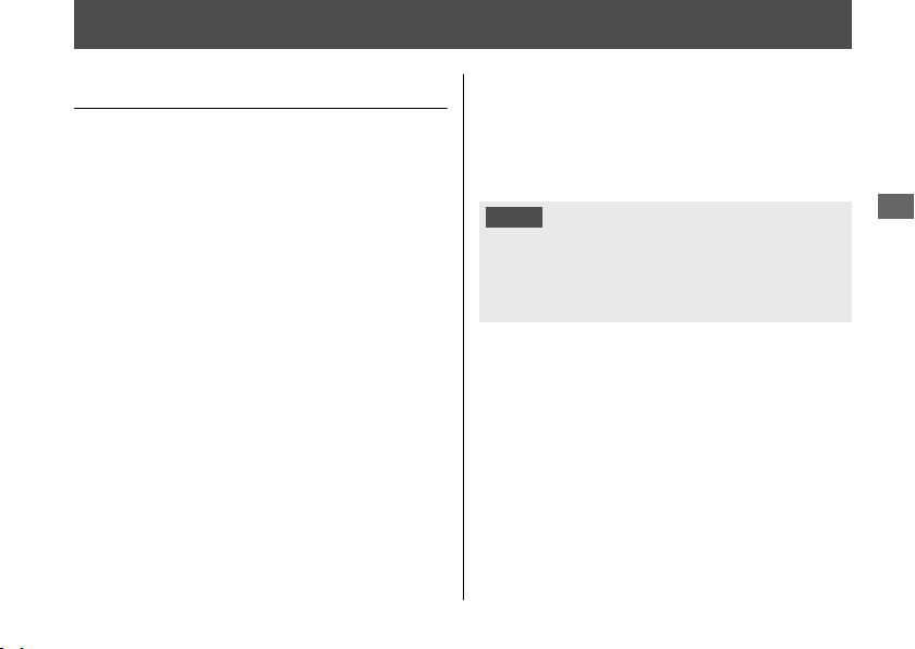
Burned-out Light Bulb
2
#
License Plate Light Bulb
1.
2.
3.
Electrical Trouble u Burned-out Light Bulb
Troubleshooting
106
Cover packing
Screws
License light
cover
Bulb
Continued
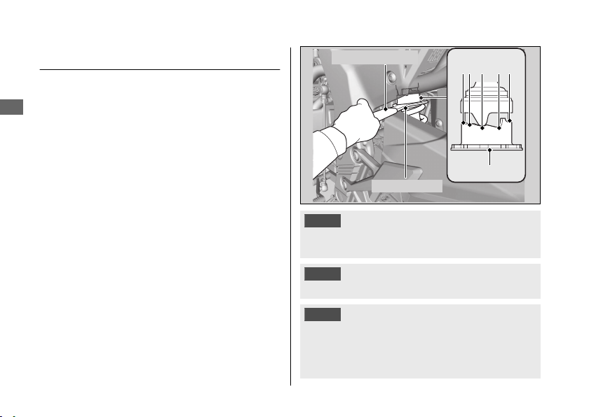
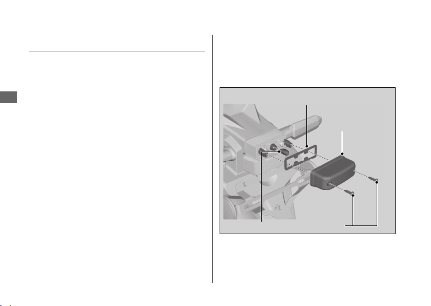
Blown Fuse
2
#
Fuse Box Fuses
1.
2
2.
3.
4.
5.
Electrical Trouble u Blown Fuse
Troubleshooting
107
Fuse box covers
Spare fuses
#
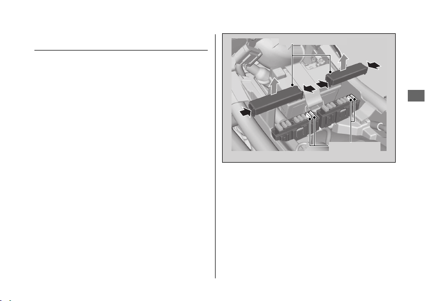
Main Fuse
1.
2
2.
3.
u
4.
NOTICE
Electrical Trouble u Blown Fuse
Troubleshooting
108
Starter magnetic
switch
Spare main fuse
Main fuse
Wire connector

Keys.....................................................................
Instruments, Controls, & Other Features...
Caring for Your Vehicle..................................
Storing Your Vehicle.......................................
Transporting Your Vehicle ............................
You & the Environment .................................
Vehicle Identification Number.....................
Emission Control Systems .............................
Catalytic Converter .........................................
Oxygenated Fuels............................................
Authorized Manuals .......................................
Warranty Coverage and Service ..................
Honda Contacts ...............................................
Reporting Safety Defects ..............................
Information
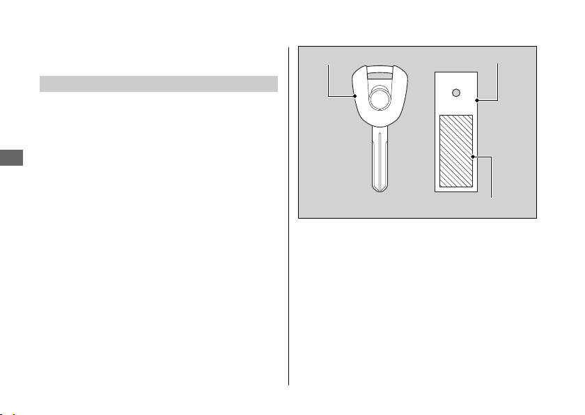
Keys
Ignition Key
Keys
Information
110
Ignition key Key tag
Key number and bar code

Instruments, Controls, &
Other Features
Ignition Switch
Engine Stop Switch
Odometer
Tripmeter
Document Bag
2
Instruments, Controls, & Other Features
Information
111
Continued

Ignition Cut-off System
Assist-slipper Clutch System
Instruments, Controls, & Other Features
Information
112

Caring for Your Vehicle
Washing
1.
2.
u
3.
4.
u
5.
6.
u
u
Caring for Your Vehicle
Information
113
Continued

#
Washing Precautions
●
u
u
●
u
●
u
●
u
●
u
●
u
●
u
Caring for Your Vehicle
Information
114

Aluminum Components
●
●
Panels
●
●
●
Caring for Your Vehicle
Information
115
Continued
Windscreen
NOTICE
Caring for Your Vehicle
Information
116
Exhaust Pipe and Muffler
NOTICE
Caring for Your Vehicle
Information
117

Storing Your Vehicle
●
● 2
●
●
● 2
u
-
USA
Honda Winter Storage Guide
Canada
Storing Your Vehicle
Information
118

Transporting Your Vehicle
NOTICE
Transporting Your Vehicle
Information
119

You & the Environment
Choose Sensible Cleaners
Recycle Wastes
You & the Environment
Information
120
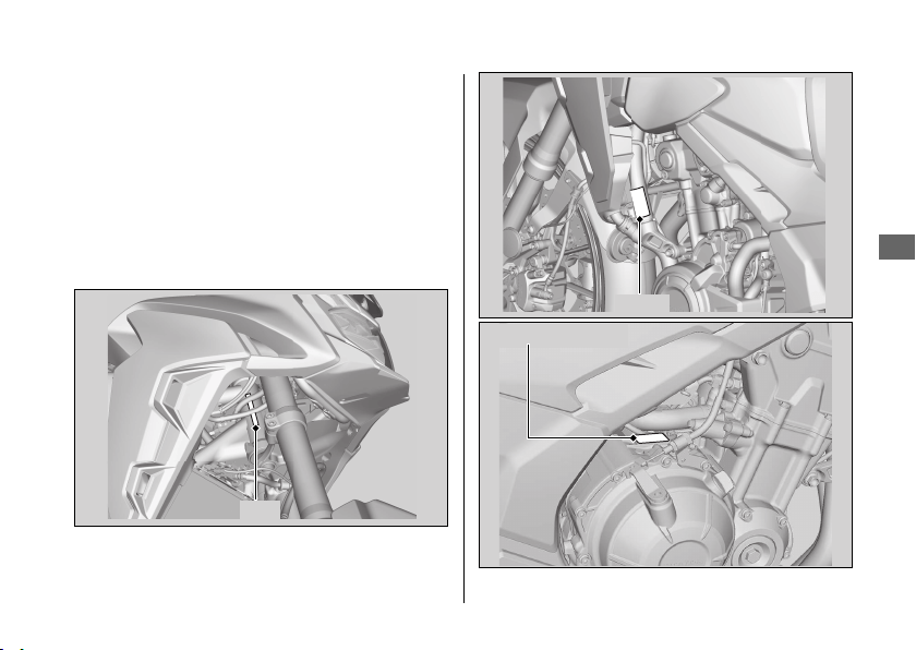
Vehicle Identification
Number
Vehicle Identification Number
Information
121
VIN
VIN
Engine number
Emission Control Systems
Exhaust Emission Requirements
USA
Emission Control Systems
Information
122
Vehicle emission control information label
Canada only
Vehicle emission control information label
Noise Emission Requirements
Exhaust Emission Control System
#
PGM-FI System
#
Ignition Timing Control System
#
Secondary Air Injection System
#
Catalytic Converters
Evaporative Emission Control System
50 STATE (meets California)
Emission Control Systems
Information
123
Continued

Crankcase Emissions Control System
Fuel Permeation Emission Control
Noise Emission Control System
#
TAMPERING WITH THE NOISE CONTROL
SYSTEM IS PROHIBITED:
#
AMONG THOSE ACTS PRESUMED TO
CONSTITUTE TAMPERING ARE THE
FOLLOWING ACTS:
●
●
●
●
Emission Control Systems
Information
124

Problems Affecting Vehicle Exhaust
Emissions
●
●
●
●
Emission Control Systems
Information
125

Catalytic Converter
●
●
●
Catalytic Converter
Information
126
Oxygenated Fuels
●
u
●
NOTICE
Oxygenated Fuels
Information
127
Description
USA
Authorized Manuals
USA
Canada
USA
USA
Order online: www.helminc.com
Order Toll Free: 1-888-CYCLE93
Authorized Manuals
Information
128
Warranty Coverage and
Service
Coverage
●
●
●
USA
Canada
USA
Warranty Coverage and Service
Information
129
Continued

Statement on Warranty Coverage for
Aftermarket and Recycled Parts
Warranty Coverage and Service
Information
130

Service
Warranty Coverage and Service
Information
131
Honda Contacts
American Honda Motor Co., Inc.
https://powersports.honda.com/
contact-us
Canada
●
●
●
●
Honda Contacts
Information
132
Your Honda Dealer
USA
Honda Contacts
Information
133

Reporting Safety Defects
USA
https://www.safercar.gov;
https://www.safercar.gov.
Reporting Safety Defects
Information
134

Canada
www.tc.canada.ca/recalls
www.tc.canada.ca/rappels
https://www.tc.gc.ca/roadsafety
Reporting Safety Defects
Information
135
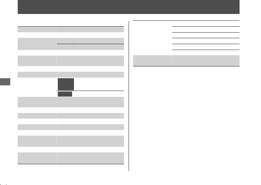
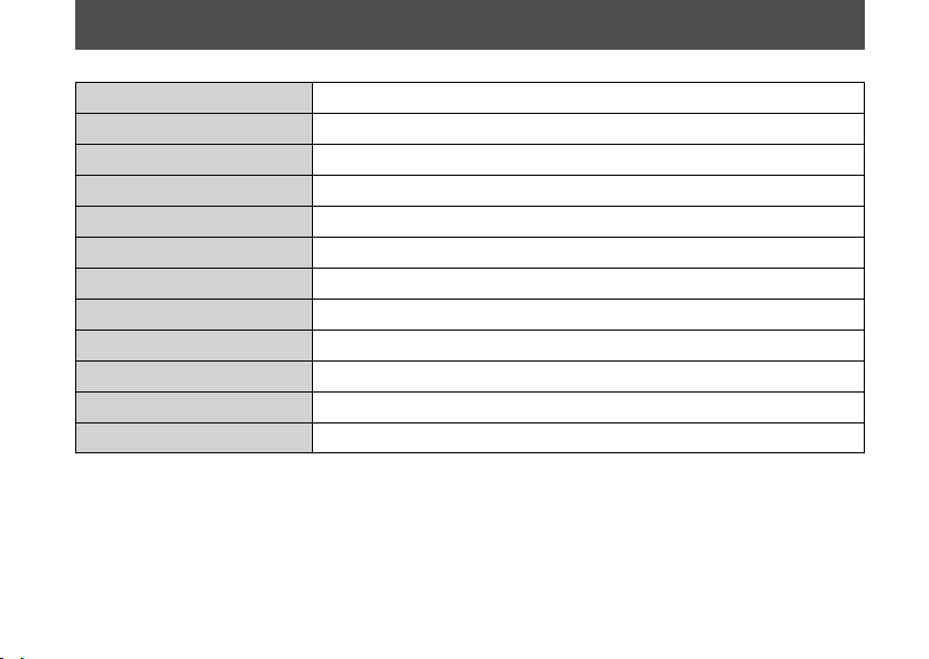
Specifications
■ Main Components
Overall length 84.8 in (2,155 mm)
Overall width 32.7 in (830 mm)
Overall height
Lowest 55.5 in (1,410 mm)
Highest 56.9 in (1,445 mm)
Wheelbase 56.9 in (1,445 mm)
Minimum ground
clearance
7.1 in (180 mm)
Caster angle 27.5°
Trail 4.3 in (108 mm)
Curb weight
50 STATE
(meets
California)
439 lb (199 kg)
Canada
437 lb (198 kg)
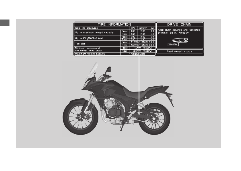
Maximum weight
capacity
*1
386 lb (175 kg)
Passenger capacity Rider and 1 passenger
Minimum turning radius
7.9 ft (2.40 m)
Displacement 28.7 cu-in (471 cm
3
)
Bore x stroke
2.64 x 2.63 in (67.0 x 66.8 mm)
Compression ratio 10.7:1
Fuel
Unleaded gasoline
Recommended: 86 PON or higher
Tank capacity 4.62 US gal (17.5 L)
Battery
YTZ8V
12 V- 7.0 Ah (10 HR)
Gear ratio
1st 3.285
2nd 2.105
3rd 1.600
4th 1.300
5th 1.150
6th 1.043
Reduction ratio
(primary / final)
2.029 / 2.733
Specifications
136
■ Service Data
Tire size
Front 110/80R19M/C 59H
Rear 160/60R17M/C 69H
Tire type Radial, tubeless
Recommended
Tire
Front DUNLOP MIXTOUR
Rear DUNLOP MIXTOUR
Tire air pressure
Front 29 psi (200 kPa, 2.00 kgf/cm
2
)
Rear 41 psi (280 kPa, 2.80 kgf/cm
2
)
Minimum tread
depth
Front 0.06 in (1.5 mm)
Rear 0.08 in (2.0 mm)
Spark plug (standard) CPR8EA-9 (NGK)
Spark plug gap
0.03 - 0.04 in (0.8 - 0.9 mm)
Idle speed
(non-
adjustable)
1,200 ± 100 rpm
Recommended
engine oil
API Service Classification SJ or higher
except oils labeled as energy conserving or
resource conserving on the circular API
service label, SAE 10W-30, JASO T 903
standard MA, Pro Honda GN4 4-stroke oil
(USA & Canada) or Honda 4-stroke oil, or
an equivalent motorcycle oil
Engine oil
capacity
After draining
2.5 US qt (2.4 L)
After draining
& engine oil
filter change
2.7 US qt (2.6 L)
After
disassembly
3.3 US qt (3.1 L)
Recommended
brake fluid
Honda DOT 4 Brake Fluid
Cooling system
capacity
1.39 US qt (1.32 L)
Recommended
coolant
Pro Honda HP Coolant
Recommended
drive chain
lubricant
Pro Honda HP Chain Lube or equivalent
Drive chain slack 1 1/4 - 1 5/8 in (30 - 40 mm)
Standard drive
chain
DID520VF or RK520MOZX
No. of links 112
Standard sprocket
size
Drive sprocket 15T
Driven sprocket 41T
Specifications
Specifications
137
■ Bulbs
Headlight LED
Brake light/Taillight LED
Front turn signal/Position light LED
Rear turn signal LED
License plate light 12 V-5 W
■ Fuses
Main fuse 30 A
Other fuse 30 A, 15 A, 10 A, 7.5 A
Specifications
Specifications
138
Information Record
139
WARNING:

PRINTED IN USA
00X31-MKP-C300
31MKPC30