Loading ...
Loading ...
Loading ...

TwK-88 & TwK-D8 Installation Manual
1
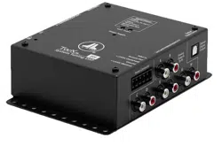
Power Connections
The TwK
™
has a 5-pin “Power Connector” jack located next to the “Analog
Outputs”. The Power Connector jack accepts the removable 5-pin plug and is
used to make the connections below.
Plug Connection Description
Power Connector
+12VDC (Battery) Positive (+12V) Power Connection
Ground Negative (GND) Ground Connection
+12VDC (Switched) Positive (+12V) Turn-On Input
Remote Out Positive (+12V) Turn-On Output
Valet In Negative (GND) Ground Input (used to activate Valet Mode)
Never make power connections with a “live” wire. Always disconnect
the vehicle’s negative battery post before making any connections or
adjustments to 12V power connections! Failure to make safe, tight,
high-integrity connections can result in fire and extensive damage.
1. Disconnect the vehicle’s NEGATIVE battery post connection and secure the
disconnected cable to prevent accidental reconnection during installation.
This is an essential safety precaution during installation!
2. +12VDC (Battery): Connect to a constant positive (+12V) source. The
internal circuitry of this connection is equipped with a self-resetting fuse
designed to protect the unit internally. To protect the vehicle and its
electrical system from damage, always install an appropriate fuse within
18 inches (45 cm) of the +12V connection point. If this is the only device
using the connection point, we recommend using a 1A fuse.
3. Ground: Connect to a clean, solid metal grounding point. Ideally, the
+12VDC (Battery) and Ground connections should be run to the same
distribution points that the amplifiers use for their power and ground
connections. This will minimize the possibility of noise in the system.
4. +12VDC (Switched): This connection is used to turn-on the TwK
™
and
should be connected to the positive (+12V) remote turn-on output of your
source unit or FiX
™
82 OEM Integration DSP.
5. Remote Out: This connection provides a positive (+12V) turn-on voltage
(100 mA limit) to activate other aftermarket signal processors or amplifiers
(similar to an aftermarket head unit’s remote turn-on lead). If your
equipment requires more than 100 mA total for activation, this connection
can be used to trigger a relay to control the equipment in your system.
6. Valet In: When connected to negative ground, this input activates the
Valet Mode Preset and will remain active until the ground connection is
removed. This allows you to activate a single preset using an alternate, user
defined method, without using the DRC-200 Digital Remote Controller.
When active, this preset will override any preset currently selected
by the DRC-200. Refer to the TwK
™
-TüN
™
Overview included with the
downloaded TüN
™
Software for detailed info about the Valet Mode Preset.
Loading ...
Loading ...
Loading ...