31-5000335 Rev. 0 03-19 GEA
Installation Instructions
for your new
Before you begin - Read these instructions completely and carefully.
IMPORTANT – OBSERVE ALL GOVERNING CODES AND ORDINANCES.
Note to Installer – Be sure to leave these instructions with the Consumer.
Note to Consumer – Keep these instructions with your Owner’s Manual for future reference.
RAK4002D
Junction Box Kit
For AZ45/AZ65 Series Zoneline
WARNING
RISK OF ELECTRIC SHOCK.
Disconnect the electrical power supply before
wiring connections.
Tools Needed
• 5/16” Nut Driver
• 1/4” Nut Driver
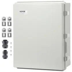
Parts Included
• 2 Junction box assemblies
• Mounting screws (4 for steel, and 3 for molded
plastic BMC)
• Wire retaining clip
Important Notes
• This unit must be properly grounded.
• Connections are made inside this junction box
assembly.
• This kit provides for connection of 1/2” trade
size electrical conduit and connection to a
wiring system in accordance with the National
Electric Code. ANSI/NFPA No. 70-2014.
It also provides for use with optional sub-
base and chaseway RAK204U/RAK205CW,
RAK204D15*, RAK204D20*, RAK204D30*,
RAK204E15*, RAK204E20*, and RAK204E30*.
• This kit contains 2 junction boxes, one for use
on AZ45/AZ65 series Zonelines with steel
control box cover and one for use on units with
molded plastic BMC control box cover.
* All Series
INSTALLATION NOTES
Reference Installation Instructions in the Zoneline
Owner’s Manual.
A. Branch Circuit Connection 230/208 volt
To connect branch circuit to unit using
direct wiring, use properly rated wire nuts
and enclose fully within junction box.
B. For use with sub-base and chaseway
Branch circuit wires can be run from the
sub-base, up the chaseway and into the
junction box where connections are made.
Electrical connections can be made directly
to the branch circuit with properly rated
wire nuts or by plug through receptacle
of appropriate sub-base. See additional
Installation Instructions with the sub-base kit.
Power supply kits or unit cords can be run
from the junction box, down the chaseway
and into the sub-base.
2
2C. ATTACH WIRING USING A SUB-BASE
AND CHASEWAY (sold separately)
1. Remove the rectangular knockout at the bottom
of the junction box. Remove the rectangular
knockout at the right end of the sub-base.
2. Wiring is placed between the two halves of
the chaseway. Observe the orientation of the
chaseway.
3. Align the screw holes and secure the halves
together using two screws provided with
chaseway.
4.
Slide the upper end of chaseway with wiring protruding
into rectangular knockout opening in the junction box.
Be sure chaseway side flanges are on the inside of
the box. Drive one screw (provided with chaseway)
through the junction box bottom into the chaseway side
flange. Insert lower end of chaseway into rectangular
hole in sub-base and slide to right into the rectangular
knockout making sure chaseway side flanges are inside
the sub-base. Route wire toward the center of the
sub-base. Drive one screw (provided with sub-base/
chaseway kit) through the sub-base slotted hole into
chaseway side flange hole.
ZONELINE SERIES – DIRECT ELECTRICAL CONNECTION
Installation Instructions
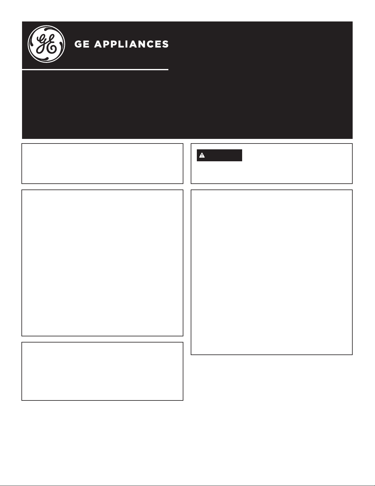
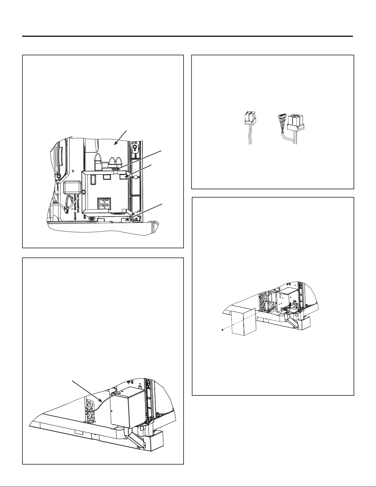
STEP 1A. ALL MODELS
Remove the room cabinet by pulling it out at the bottom
to release it (1); then lift it up to clear the rail along the
unit top (2).
STEP 1B.
Check the control box cover on the front of the
Zoneline, just below the unit controls.
• If steel, use junction box labeled RAK4002C.
Proceed to step 2.
• If molded plastic BMC, use junction box labeled
RAK4002D. Proceed to step 3.
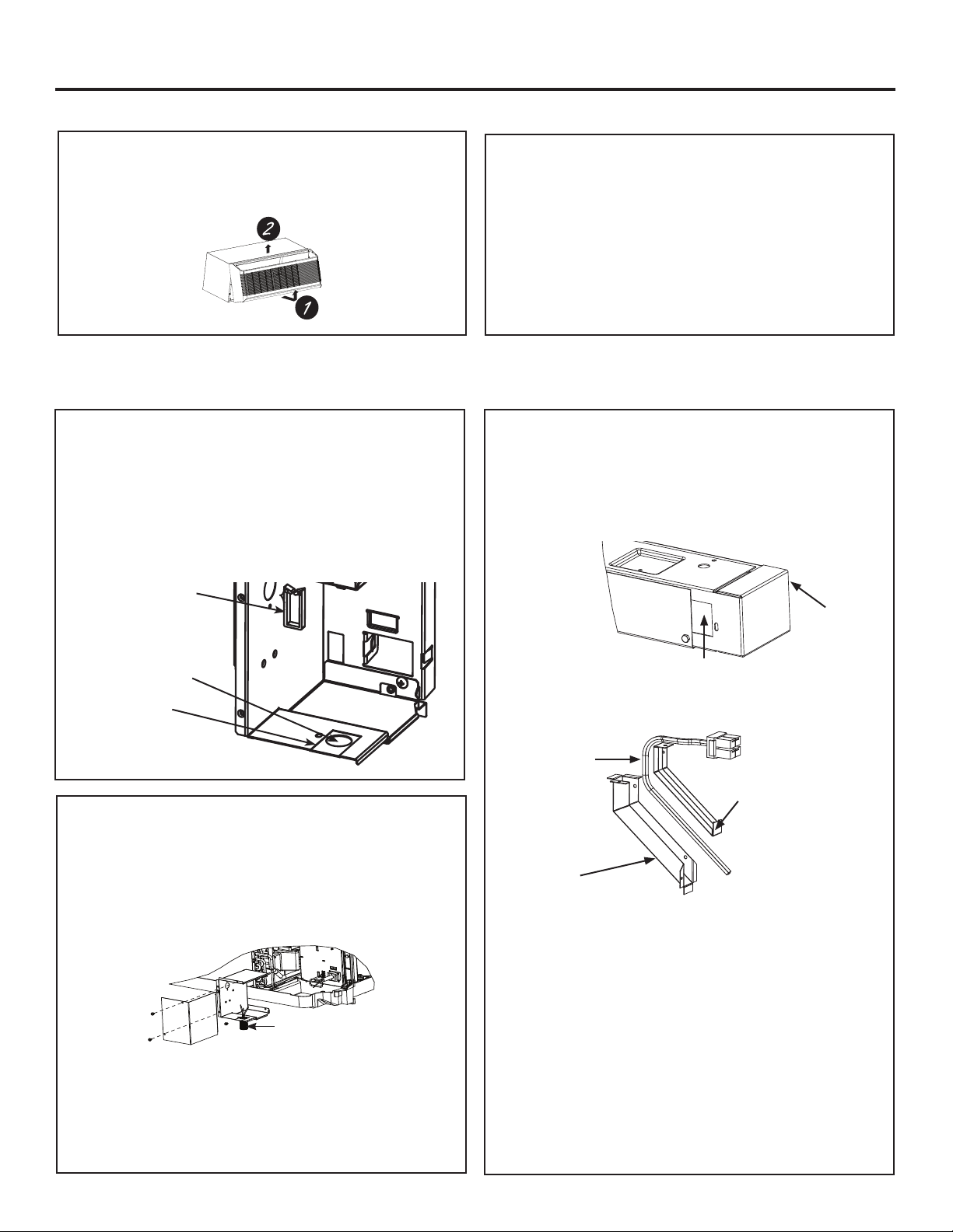
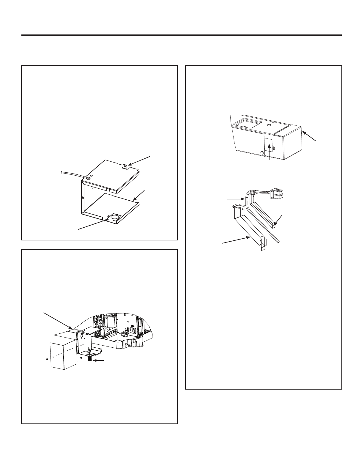
2A. JUNCTION BOX KNOCKOUT
For conduit installation: Use the round hole in the
bottom of the junction box base. Proceed to Step 2B.
For sub-base/chaseway installation: Remove
rectangular knockout from junction box base.
Proceed to Step 2C.
Round
Conduit
Knockout
Rectangular
Chaseway
Knockout
Mount wire
retaining
clip through
this hole
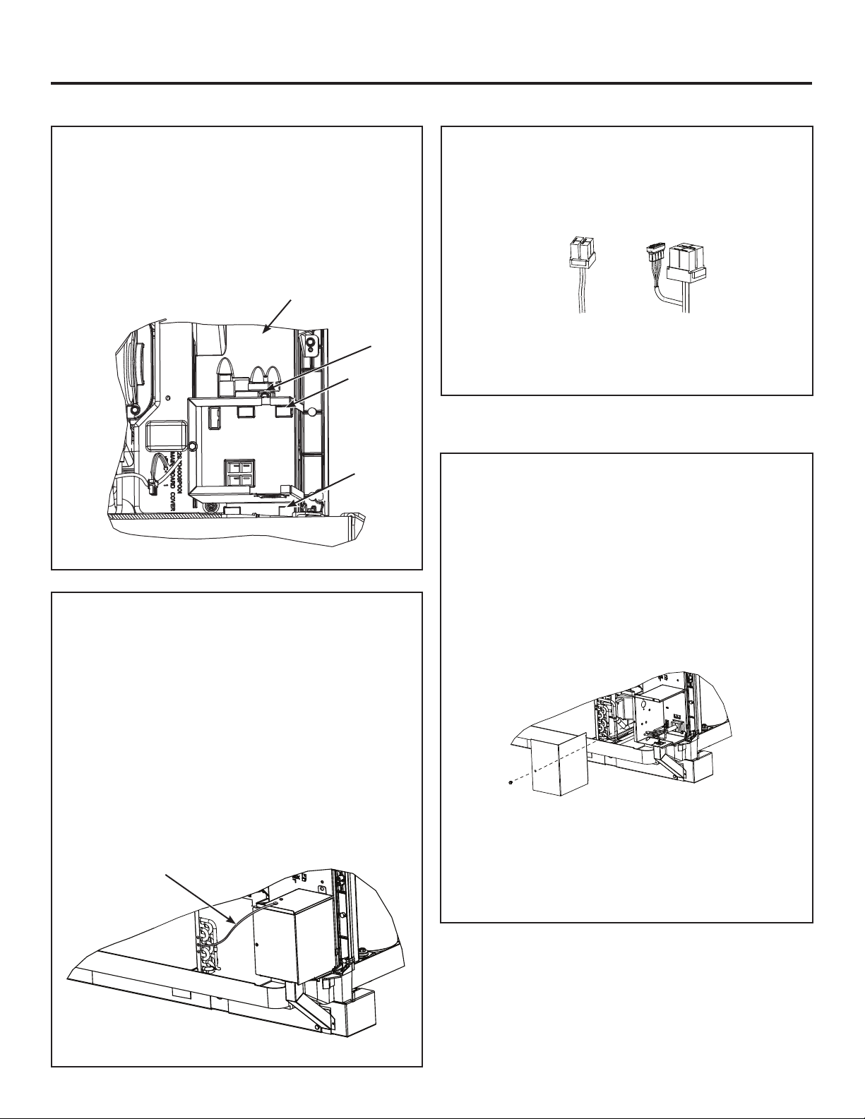
STEP 2: ZONELINE MODELS WITH STEEL CONTROL BOX COVER
2B. ATTACH WIRING USING A
CONDUIT
1. Use the round hole at the bottom of the junction box to
attach conduit coming from the branch circuit. Attach
the conduit using proper conduit connector and bring
wires into the junction box. Leave 6” of wire free at the
end of the conduit to allow connections to be made.
2. If a fuse and fuse holder are to be used, the
knockout at the side of the box is for mounting
a Buss Fuse holder. Be sure the fuse and fuse
holder are of the same rating as the branch circuit.
Leadwires at the fuse can be either soldered in
place or attached using UL-listed 1/4” female
(receptacle) crimp connectors.
Conduit
Knockout
Sub-base
Wiring
Chaseway cover
Chaseway
3
2F.
INSTALL JUNCTION BOX COVER
1. Carefully tuck all wires and connections back
inside the junction box. Be sure there are no
loose connections or stray uninsulated wires
exposed.
2. Align junction box cover ensuring mating tabs
base are inserted into slots on cover. Drive
screw securing cover in place.
3. Check to ensure all wires are inside junction box
and no wires are pinched between cover and
base.
4. Turn power back on to the installed unit and
check operation.
5. Replace the Zoneline front cabinet.
DIRECT ELECTRICAL CONNECTION
Installation Instructions
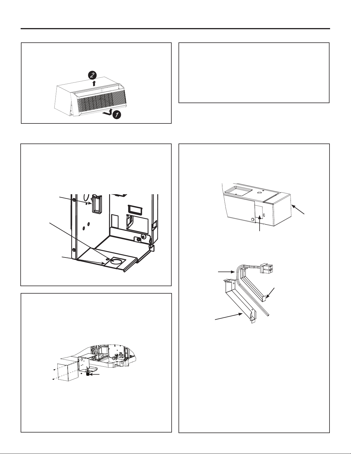
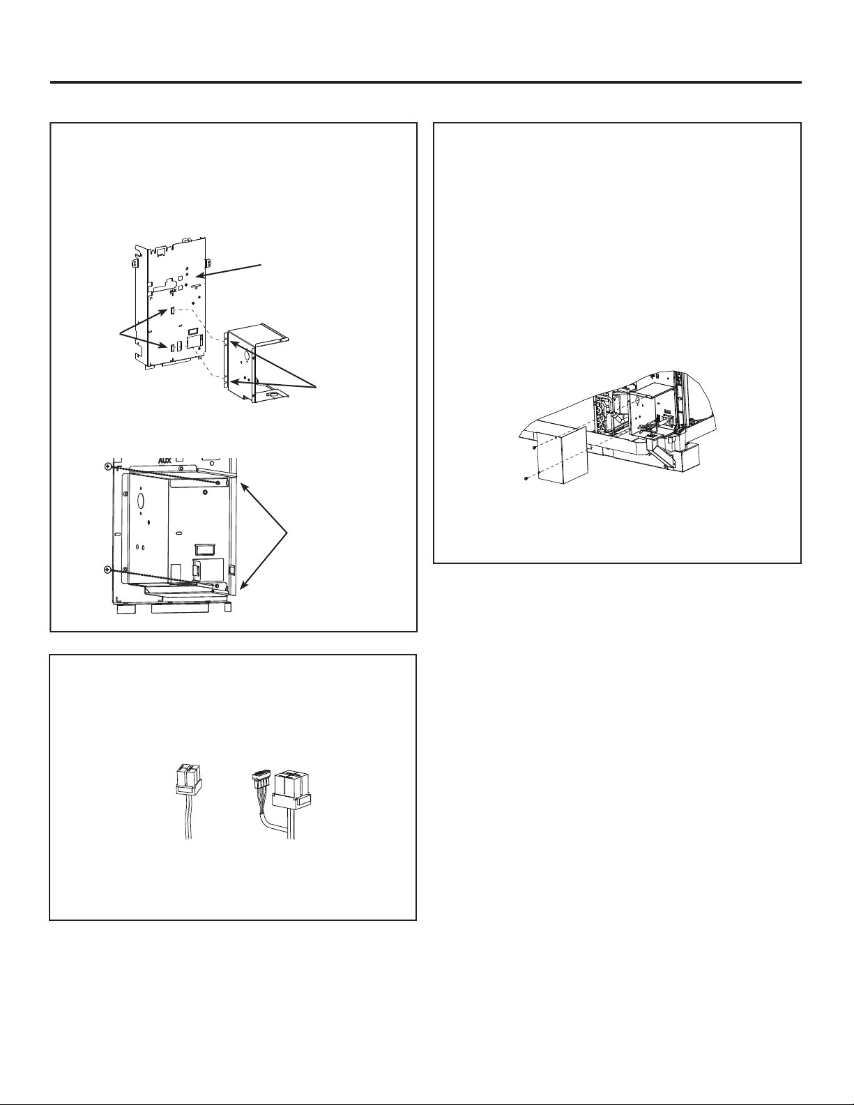
2D. INSTALL JUNCTION BOX
Install the junction box by inserting the left tabs
into control box cover slots, and aligning two screw
holes inside the upper and lower enclosure.
Tabs on
Junction
Box
Slots on
Control
Box Cover
Drive the two screws until they are secure.
Screws
Steel
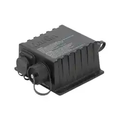
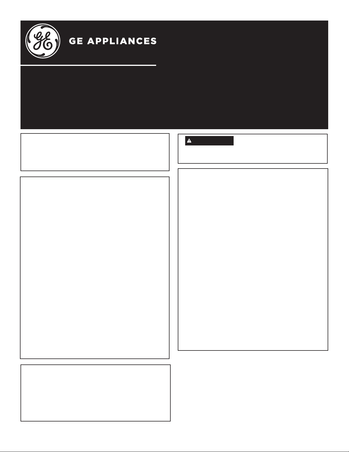
2E. CONNECT THE POWER SUPPLY KIT
Plug the power connectors, ensuring plug is fully seated
and locking tabs are engaged.
15A 20A and 30A
For 20 AMP and 30 AMP power supply kits, a
second smaller plug must also be plugged into its
corresponding mating connector.

4
3C. ATTACH WIRING USING A SUB-BASE
AND CHASEWAY (sold separately)
1. Remove the rectangular knockout at the bottom of
the junction box. Remove the rectangular knockout
at the right end of the sub-base.
2. Wiring is placed between the two halves of
the chaseway. Observe the orientation of the
chaseway.
3. Align the screw holes and secure the halves
together by using a Type A screw in the lower or
longer section of the chaseway. The top screw
must be inserted in the next step.
4.
Slide the upper end of chaseway with wiring protruding
into rectangular knockout opening in the junction box.
Be sure chaseway side flanges are on the inside of the
box. Drive one screw (provided with chaseway) through
the junction box bottom into the chaseway side flange*.
Insert lower end of chaseway into rectangular hole in
sub-base and slide to right into the rectangular knockout
making sure chaseway side flanges are inside the sub-
base. Route wire toward the center of the sub-base.
Drive one screw (provided with sub-base/chaseway kit)
through the sub-base slotted hole into chaseway side
flange hole.
* Align the upper screw holes and use a Type A screw to
complete the chaseway assembly.
Installation Instructions
3A. SELECT ELECTRICAL
CONNECTION METHOD
• For Conduit Installation: Use the hole in the bottom
of the junction box to connect flexible conduit. Hole
is designed for 1/2” connector. Proceed to Step 3B.
• For Sub-Base Installation: Remove the rectangular
knockout in the bottom of the junction box base to
accept the chaseway from the sub-base. Proceed to
Step 3C.
STEP 3: INSTALL JUNCTION BOX ON MOLDED PLASTIC BMC
CONTROL BOX COVER
Screw
Tab
Junction Box
Base
Rectangular
knockout
3B. ATTACH WIRING USING A
CONDUIT
1. Use the round hole at the bottom of the junction box to
attach conduit coming from the branch circuit. Attach
the conduit using proper conduit connector and bring
wires into the junction box. Leave 6” of wire free at the
end of the conduit to allow connections to be made.
2. If a fuse and fuse holder are to be used, the
knockout at the side of the box is for mounting
a Buss Fuse holder. Be sure the fuse and fuse
holder are of the same rating as the branch circuit.
Leadwires at the fuse can be either soldered in
place or attached using UL-listed 1/4” female
(receptacle) crimp connectors.
Conduit
Knockout
Sub-base
Wiring
Chaseway cover
Chaseway
Ground wire
5
Installation Instructions
3G.
INSTALL JUNCTION BOX COVER
1. Carefully tuck all wires and connections back
inside the junction box. Be sure there are no
loose connections or stray uninsulated wires
exposed.
2. Install junction box cover by rotating the cover to
the right to locate the rear slots onto the mating
tabs on the rear of the junction box base. Rotate
back left to align the screw holes on the front
and install he screw.
3. Check to ensure all wires are inside junction box
and no wires are pinched between cover and
base.
4. Turn power back on to the installed unit and
check operation.
5. Replace the Zoneline front cabinet.
ZONELINE SERIES – DIRECT ELECTRICAL CONNECTION
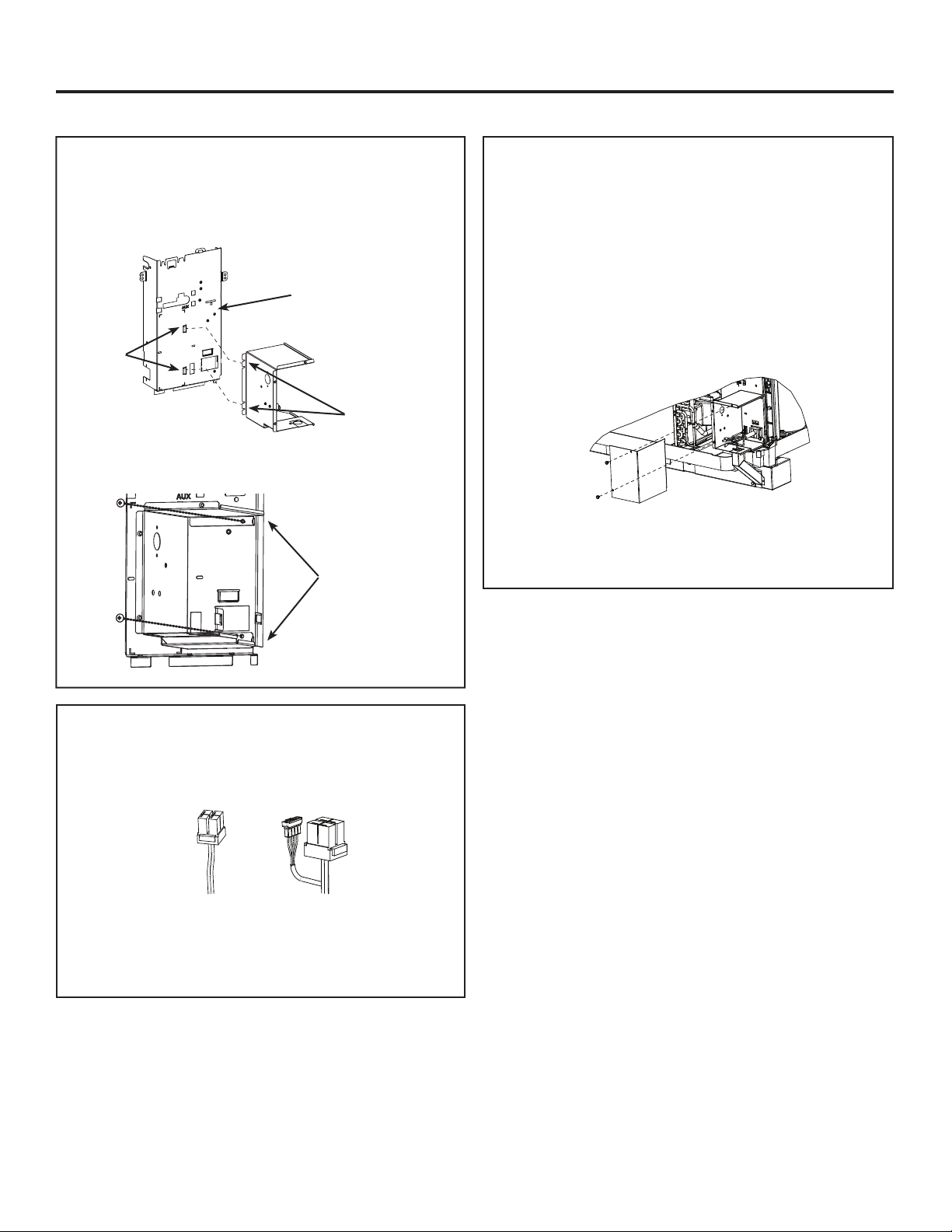
3E. ATTACH JUNCTION BOX
GROUND WIRE
It is critical to attach the junction box ground wire to
the end sheet of the indoor coil. If the end sheet only
has two holes with attached ground wires, remove
the LOWER ground wire, add the loose end of the
junction box ground wire and attach both wires to the
end sheet using the same screw.
On some models, there will be an empty screw hole
between the two attached ground wires. On these
models, attach the loose end of the junction box
ground wire to this empty hole using the included
green fine threaded screw.
3D.
• Install the junction box base by inserting the upper
and lower tabs into the upper and lower slots on the
molded control box cover.
• Use provided 5/16” double helix screw to fasten
the tab on the top of the junction box base to the
molded front control box cover.
Lower
Slots
Upper
Slots
Screw
Boss
Molded Plastic Cover
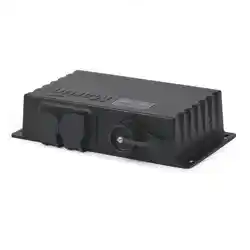
3F. CONNECT THE POWER
SUPPLY KIT
Plug the power connectors, ensuring plug is fully
seated and locking tabs are engaged.
15A 20A and 30A
For 20 AMP and 30 AMP power supply kits, a
second smaller plug must also be plugged into its
corresponding mating connector.
Ground wire
31-5000335 Rev. 0 03-19 GEA
Outil nécessaire
• Tournevis à douille 5/16 po
• Tournevis à douille 1/4 po
NOTES D’INSTALLATION
Les instructions d’installation de référence
se trouvent dans le manuel d’utilisation du
Zoneline.
A. Branchement du circuit de dérivation
230/208 volt
Pour brancher le circuit de dérivation à
l’appareil à l’aide d’une connexion directe,
utilisez des capuchons de connexion du
calibre approprié et insérez-les complètement
à l’intérieur de la boîte de jonction.
B. Utilisation avec un socle et un chemin de
câble
L’acheminement du câble du circuit de
dérivation se fait depuis le socle vers le
haut par le chemin de câble jusque dans
la boîte de jonction où les connexions sont
effectuées. Les connexions peuvent se
faire directement sur le circuit de dérivation
à l’aide de capuchons de connexion du
calibre approprié ou de fiches passant par le
réceptacle de socle approprié. Consultez les
instructions d’installation livrées avec le socle.
Pièces incluses
• Ensemble de boîte de jonction (2)
• Vis de montage (4 pour acier, et 3 pour
plastique moulé BMC).
• Pince de retenue de câble
Remarques importantes
• Cet appareil doit être mis à la terre
correctement.
• Les connexions sont effectuées à l’intérieur de
cette boîte de jonction.
• Cet ensemble permet de brancher un conduit
électrique d’un diamètre nominal de ½ po
à un circuit de câblage en conformité avec
le National Electric Code. ANSI/NFPA No.
70-2014. L’ensemble permet aussi l’utilisation
avec un socle et un chemin de câble en option,
modèles RAK204U/RAK205CW, RAK204D15*,
RAK204D20*, RAK204D30*, RAK204E15*,
RAK204E20*, et RAK204E30*.
• Cette trousse contient 2 boîtes de jonction,
l’une pour utilisation avec boîtes Zoneline des
séries AZ45/AZ65 dotées d’un couvercle de
boîte de commande en acier, et l’autre pour
utilisation avec celles dotées d’un couvercle
de boîte de commande en plastique moulé
préimprégné (BMC).
* Toutes les séries
Instructions d’installationde
votre nouvel ensemble de boîte
de jonction
Avant de commencer – Lisez ces instructions attentivement et en totalité.
IMPORTANT – OBSERVEZ TOUS LES CODES ET RÈGLEMENTS EN VIGUEUR.
Remarque à l’installateur – Assurez-vous de remettre ces instructions au consommateur.
Remarque au consommateur – Conservez ces instructions avec le manuel d’utilisation pour
consultation ultérieure.
RAK4002D
Modèles Zoneline Séries AZ45/AZ65
AVERTISSEMENT
Risque de choc électrique.
Coupez l’alimentation électrique avant de
connecter les fils.
2
2C. ATTACHER LE CÂBLE À L’AIDE D’UN
SOCLE ET D’UN CHEMIN DE CÂBLE
(VENDUS SÉPARÉMENT)
1. Enlevez la débouchure rectangulaire dans le bas de
la boîte de jonction. Enlevez aussi la débouchure
rectangulaire à l’extrémité droite du socle.
2. Le câble est placé entre les deux moitiés du chemin de
câble. Observez l’orientation du chemin.
3. Alignez les trous de vis et fixez les moitiés ensemble à
l’aide des deux vis fournies avec le chemin de câble.
4.
Glissez l’extrémité supérieure du chemin, en faisant
dépasser le câble dans la boîte de jonction par l’orifice de
la débouchure. Assurez-vous que les rebords du chemin
se trouvent à l’intérieur de la boîte de jonction. Vissez une
vis (fournie avec le chemin de câble) à travers le fond de la
boîte de jonction jusque dans le rebord du chemin. Insérez
l’extrémité inférieure du chemin dans l’orifice rectangulaire
du socle et glissez-la vers la droite dans la débouchure
rectangulaire, en vérifiant que les rebords du chemin se
trouvent dans le socle. Acheminez le câble vers le centre du
socle. Vissez une vis (fournie avec l’ensemble socle-chemin
de câble) à travers la fente du socle jusque dans le trou du
rebord du chemin de câble.
SÉRIE ZONELINE – CONNEXION ÉLECTRIQUE DIRECTE
Instructions d’installation
ÉTAPE 1B.
Vérifiez le couvercle du boîtier de commande situé
à l’avant de la Zoneline, juste en dessous des
commandes de l’appareil.
• S’il s’agit d’acier, utilisez une boîte de jonction
étiquetée RAK4002C. Passez à l’étape 2.
• Si le plastique BMC est moulé, utilisez une boîte de
jonction étiquetée RAK4002D. Passez à l’étape 3.
2A. RETIRER LA DÉBOUCHURE POUR
CÂBLE DE LA BOÎTE DE JONCTION
Pour l’installation avec conduit électrique : Utilisez
l’orifice rond dans le fond de la base de la boîte de
jonction.Allez à l’étape 2B..
Pour l’installation avec socle/passage pour câble :
Retirez la débouchure rectangulaire pour câble de
la base de la boîte de jonction. Allez à l’étape 2C.
débouchure de
conduit rond
Knock chasse
rectangulaire /
knock-out
montez le fil
retaing clip à
travers ce trou
ÉTAPE 2 : MODÈLES ZONELINE AVEC COUVERCLE DE
BOÎTE DE COMMANDE EN ACIER
2B. ATTACHER LE CÂBLE À L’AIDE D’UN
CONDUIT
1. Utilisez l’orifice rond dans le bas de la boîte de jonction
pour attacher le conduit provenant du circuit de dérivation.
Attachez le conduit à l’aide d’un raccord pour conduit
approprié et faites passer les fils dans la boîte de jonction.
Laissez une longueur de fils de 15 cm (6 po) à l’extrémité
du conduit pour effectuer les connexions.
2. Si un fusible ou un porte-fusible est utilisé, la débouchure
sur le côté de la boîte sert à monter un porte-fusible de
type Buss. Assurez-vous que le fusible et le porte-fusible
sont du même calibre que le circuit de dérivation. Les
fils de connexion au fusible peuvent être soudés ou fixés
à l’aide de raccords à sertir femelles (prises) de ¼ po
homologués UL.
Conduit
Knockout
sous base
câblage
couverture de chasse
Chaseway
ÉTAPE 1A. RETIRER LE PANNEAU
FRONTAL DU LOGEMENT
Pour retirer le panneau frontal, tirez sa partie inférieure vers
l’extérieur et soulevez le panneau pour le dégager du rail dans
le haut de l’appareil (2).
3
2F.
POSER LE COUVERCLE DE LA
BOÎTE DE JONCTION
1. Placez avec précaution tous les fils et les connexions
à l’intérieur de la boîte de jonction. Vérifiez l’absence
de connexions lâches et de fils dénudés exposés
sans isolant.
2. Alignez le couvercle de la boîte de jonction en vous
assurant que les languettes sont insérées dans les
fentes correspondantes du couvercle. Vissez la vis qui
fixe le couvercle.
3. Vérifiez que tous les fils se trouvent à l’intérieur de la
boîte de jonction et qu’aucun fil n’est coincé entre le
couvercle et la base.
4. Rétablissez l’alimentation électrique à l’appareil et
vérifiez le bon fonctionnement de celui-ci.
5. lacez le panneau frontal du Zoneline.
CONNEXION ÉLECTRIQUE DIRECTE
Instructions d’installation
2D. POSER LA BOÎTE DE JONCTION
Poser la boîte de jonction en insérant les languettes
de gauche dans les fentes du couvercle de la boîte de
commande, puis alignez les deux trous de vis à l’intérieur
de l’enveloppe inférieure et supérieure.
Languettes
sur la boîte
de jonction
Fentes sur le
couvercle de
la boîte de
commande
Vissez les deux vis jusqu’à ce qu’elle soient bien serrées.
Vis
acero
2E. BRANCHER LES CONNECTEURS
ÉLECTRIQUES
Branchez les connecteurs électriques, en vous assurant que
la fiche est insérée à fond, avec les languettes de verrouillage
enclenchée.
15A 20A and 30A
Pour les connecteurs de 20 et 30 ampères, une deuxième
fiche plus petite doit aussi être branchée dans la prise
correspondante.
4
Instructions d’installation
3A. SÉLECTIONNER LA MÉTHODE DE
BRANCHEMENT ÉLECTRIQUE
• Pour l’installation du conduit : Utilisez le trou dans le
bas de la boîte de jonction pour connecter le conduit
flexible. Le trou est conçu pour un connecteur 1/2
po. Allez à l’étape 3B.
• Pour l’installation du socle : Retirez la débouchure
rectangulaire dans le bas de la base de la boîte de
jonction afin d’accepter le chemin de câble du socle.
Allez à l’étape 3C.
ÉTAPE 3: INSTALLERLA BOÎTE DE JONCTION SUR LE COUVER-
CLE DE BOÎTE DE COMMANDE EN PLASTIQUE MOULÉ BMC
languette
à vis
base de la
boîte de
jonction
KO rectangulaire
3B. ATTACHER LE CÂBLE À L’AIDE
D’UN CONDUIT
1. Utilisez l’orifice rond dans le bas de la boîte de jonction
pour attacher le conduit provenant du circuit de dérivation.
Attachez le conduit à l’aide d’un raccord pour conduit
approprié et faites passer les fils dans la boîte de jonction.
Laissez une longueur de fils de 15 cm (6 po) à l’extrémité
du conduit pour effectuer les connexions.
2. Si un fusible ou un porte-fusible est utilisé, la débouchure
sur le côté de la boîte sert à monter un porte-fusible de type
Buss. Assurez-vous que le fusible et le porte-fusible sont
du même calibre que le circuit de dérivation. Les fils de
connexion au fusible peuvent être soudés ou fixés à l’aide de
raccords à sertir femelles (prises) de ¼ po homologués UL.
¿OGHWHUUH
3C. ATTACHER LE CÂBLE À L’AIDE D’UN
SOCLE ET D’UN CHEMIN DE CÂBLE
(VENDUS SÉPARÉMENT)
1. Enlevez la débouchure rectangulaire dans le bas de
la boîte de jonction. Enlevez aussi la débouchure
rectangulaire à l’extrémité droite du socle.
2. Le câble est placé entre les deux moitiés du chemin de
câble. Observez l’orientation du chemin.
3. Alignez les trous de vis et fixez les moitiés ensemble à
l’aide d’une vis de type A dans la section inférieur ou
plus longue du chemin de câble. La vis supérieure sera
insérée à l’étape suivante.
4.
Glissez l’extrémité supérieure du chemin, en faisant
dépasser le câble dans la boîte de jonction par l’orifice de
la débouchure. Assurez-vous que les rebords du chemin
se trouvent à l’intérieur de la boîte de jonction. Vissez une
vis (fournie avec le chemin de câble) à travers le fond de la
boîte de jonction jusque dans le rebord du chemin*. Insérez
l’extrémité inférieure du chemin dans l’orifice rectangulaire
du socle et glissez-la vers la droite dans la débouchure
rectangulaire, en vérifiant que les rebords du chemin se
trouvent dans le socle. Acheminez le câble vers le centre du
socle. Vissez une vis (fournie avec l’ensemble socle-chemin
de câble) à travers la fente du socle jusque dans le trou du
rebord du chemin de câble.
* Alignez les trous de vis supérieurs et utilisez une vis de type A
pour compléter l’assemblage du chemin de câble.
Knockout
sous base
câblage
couverture de chasse
Chaseway
Conduit
5
Instructions d’installation
3G.
POSER LE COUVERCLE DE LA BOÎTE
DE JONCTION
1. Placez avec précaution tous les fils et les connexions
à l’intérieur de la boîte de jonction. Vérifiez l’absence
de connexions lâches et de fils dénudés exposés
sans isolant.
2. Installez le couvercle de la boîte de jonction en le
faisant pivoter vers la droite afin de repérer les fentes
arrière sur les languettes correspondantes à l’arrière
de la base de la boîte de jonction. Faites pivoter vers
la gauche en retour pour aligner les trous de vis sur le
devant et posez la vis.
3. Vérifiez que tous les fils se trouvent à l’intérieur de la
boîte de jonction et qu’aucun fil n’est coincé entre le
couvercle et la base.
4. Rétablissez l’alimentation électrique à l’appareil et
vérifiez le bon fonctionnement de celui-ci.
5. Lacez le panneau frontal du Zoneline.
ZONELINE SERIES – DIRECT ELECTRICAL CONNECTION
3E. FIXER LE FIL DE TERRE DE LA
BOÎTE DE JONCTION
Il est crucial de fixer le fil de terre de la boîte de jonction
sur la tôle d’extrémité du serpentin intérieur. Si cette tôle
n’est dotée que de deux trous où sont fixés des fils de terre,
retirez le fil de terre INFÉRIEUR, ajoutez l’extrémité lâche
du fil de terre de la boîte de jonction et fixez les deux fils à
la tôle d’extrémité à l’aide de la même vis.
Sur certains modèles, un trou de vis libre se trouvera entre
les deux fils de terre fixés. Sur ces modèles, fixez l’extrémité
lâche du fil de terre de la boîte de jonction dans ce trou libre
à l’aide de la vis verte au filetage fin.
3D.
• Installezla base de la boîte de jonction en insérant
les languettes supérieure et inférieure dans les fentes
supérieure et inférieure sur le couvercle de la boîte de com-
mande moulée.
• Utilisez la vis en double hélice 5/16 po fournie pour fixer la
languette dans le haut de la base de la boîte de jonction sur
le couvercle de la boîte de commande moulée.
fentes
inférieures
fentes
supérieures
patron
de vis
moule en plastique
¿OGHWHUUH
3F. BRANCHER LES CONNECTEURS
ÉLECTRIQUES
Branchez les connecteurs électriques, en vous assurant que
la fiche est insérée à fond, avec les languettes de verrouillage
enclenchée.
15A 20A and 30A
Pour les connecteurs de 20 et 30 ampères, une deuxième
fiche plus petite doit aussi être branchée dans la prise
correspondante.