1 GR
ΕΝΤΟΙΧΙΖΟΜΕΝΟΣ ΦΟΥΡΝΟΣ ΚΑΙ ΕΣΤΙΕΣ
ΕΓΧΕΙΡΙΔΙΟ ΧΡΗΣΤΗ
GR
PCV 6422 X
FCO 607 /6 XL
FCO 827 /6 XL

2 GR
ΠΕΡΙΕΧΟΜΕΝΑ GR

3 GR
ΟΔΗΓΙΕΣ ΑΣΦΑΛΕΙΑΣ
-
-
-
-
-
-
-
-
-
-

4 GR
1. ΓΕΝΙΚΕΣ ΠΡΟΕΙΔΟΠΟΙΗΣΕΙΣ
-
-
-
1.1 ΔΗΛΩΣΗ ΣΥΜΒΑΤΟΤΗΤΑΣ
-
-
-
-
-
-
-
1.4 ΤΟΠΟΘΕΤΗΣΗ ΣΤΟ ΕΠΙΠΛΟ ΚΟΥΖΙΝΑΣ
-
1.2 ΟΔΗΓΙΕΣ ΑΣΦΑΛΕΙΑΣ
-
-
Όταν χρησιμοποιείτε μια ηλεκτρική συσκευή
θα πρέπει να ακολουθείτε ορισμένους βασικούς κανόνες.
-
-
-
-
1.5 ΣΗΜΑΝΤΙΚΟ
-
-
-
Απομακρύνετε το πίσω μέρος του επίπλου για να διασφαλίσε-
τε ο φούρνος αερίζεται επαρκώς. Οι εστίες θα πρέπει να έχουν
κενό προς τα πίσω τουλάχιστον 45 χιλιοστών.
1.3 ΕΓΚΑΤΑΣΤΑΣΗ
-
-
1.6 ΗΛΕΚΤΡΙΚΗ ΣΥΝΔΕΣΗ
Ο φούρνος πρέπει να γειωθεί σωστά
-
-
-
-
-
-
-
-
Σημαντικό:-
-
-
Οι κατασκευαστές δεν μπορούν να φέρουν καμία ευθύνη για
οποιαδήποτε βλάβη ή τραυματισμό ατόμων, ζώων ή αντικειμέ-
νων που προκαλούνται από τη μη σωστή γείωση του φούρνου.
-
-
-
-
-
Σημείωση: -

5 GR
06 GB
The drip tray catches the juices from grilled foods. It is only used
with the Grill, Rotisserie, or Fan Assisted Grill ; remove it from the
oven for other cooking methods.
Never use the drip tray as a roasting tray as this creates smoke
and fat will spatter your oven making it dirty.
The tray holder
The tray holder shelf is ideal for grilling. Use it in conjunction with
the drip tray. A handle is included to assist in moving the both
accessories safely. Do no leave the handle inside the oven.
3. OVEN EQUIPMENT (according to the model)
It is necessary to do an initial cleaning of the equipment
before the first use of each of them.Wash them with a sponge.
Rinse and dry off.
The simple shelf can take moulds and dishes.
The tray holder shelf is especially good for grilling things. Use it
with the drip tray.
The special profile of the shelves means they stay horizontal even
when pulled right out. There is no risk of a dish sliding or spilling.
Figure 4
Figure 5
Figure 6
Figure 7
The pizza set is designed for pizza cooking. In order to obtain the
best results the set must be used together with Pizza function.
2. INTRODUCTION OF PRODUCT
VITROCERAMIC HOB: PCV 6422 X
MAIN PARTS
1. Ø 202 Radiant Zone (1000+1200W)
2. Ø 147 Radiant Zone (1200W)
3. Ø 260 Radiant Zone (1500+900W)
4. Ø 147 Radiant Zone (1200W)
5. Vitroceramic Surface
6. Lower Casing
Figure 1
Figure 2
Figure 3
Table 1
√√
Hob - Oven
Combination Possibility
PCV 6422 X
FCO 607/6 XL FCO 827/6 XL
2
1
3
4
5
1200 W
1500+900 W
1000 W
+
1200 W
1200 W
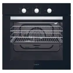
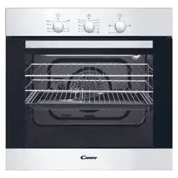
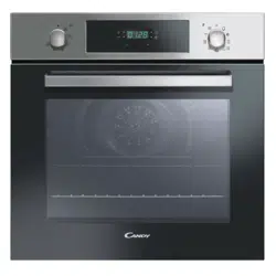
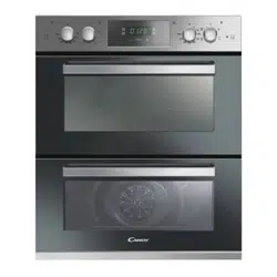
MAIN PARTS
1. Control Panel
2. Oven Door Handle
3. Oven Door
4. Tray
5. Lower Heating
Element
6. Upper Heating
Element
7. Grid
8. Racks
ΒΑΣΙΚΑ ΜΕΡΗ
2. ΠΑΡΟΥΣΙΑΣΗ ΤΟΥ ΠΡΟΪΟΝΤΟΣ
Εικόνα 1
Εικόνα 2
Εικόνα 3
Εικόνα 4
Πίνακας 1
Εστία-Φούρνος
Δυνατότητα
συνδυασμού
FCO 607/6 XL FCO 827/6 XL
PCV 6422 Χ
√ √
VITROCERAMIC HOB: PCV 6422 X
Εικόνα 5
Εικόνα 6
Εικόνα 7
δίσκος -
Ποτέ μην χρησιμοποιείτε το δίσκο συλλογής υγρών ως ταψί ψησίματος
καθώς δημιουργεί καπνούς και τα λίπη θα πιτσιλίσουν και θα λερώσουν
το φούρνο σας.
σκεύος πίτσας-
ΒΑΣΙΚΑ ΜΕΡΗ
3. ΕΞΟΠΛΙΣΜΟΣ ΦΟΥΡΝΟΥ (ανά μοντέλο)
Είναι απαραίτητο να κάνετε έναν αρχικό καθαρισμό του εξοπλι-
σμού πριν τον χρησιμοποιήστε για πρώτη φορά. Πλύνετε τα με
ένα σφουγγάρι, ξεβγάλετε και στεγνώστε. απλό ταψί -
σχάρα
Το ιδιαίτερο χαρακτηριστικό των ραφιών είναι ότι μένουν οριζόντια ακό-
μα κι όταν τραβηχτούν έξω. Δεν υπάρχει κίνδυνος να γλιστρήσει ή να πέ-
σει κάποιο σκεύος.
Η σχάρα συνδυασμού
-

6 GR
Εικόνα 8
4.1 ΣΥΣΤΗΜΑ ΑΣΦΑΛΕΙΑΣ ΤΑΨΙΩΝ
4.ΧΡΗΣΙΜΕΣ ΣΥΜΒΟΥΛΕΣ
-
4.2 ΓΚΡΙΛ
-
4.3. ΧΡΟΝΟΣ ΜΑΓΕΙΡΕΜΑΤΟΣ
-
4.4. ΚΑΘΑΡΙΣΜΟΣ ΚΑΙ ΣΥΝΤΗΡΗΣΗ
-
-
-
-
-
-
-
-
4.5 ΚΕΝΤΡΟ ΕΞΥΠΗΡΕΤΗΣΗΣ
-
Πριν καλέσετε να σημειώσετε τον σειριακό αριθμό που βρίσκε-
ται στον πίνακα με τις προδιαγραφές (βλ. εικόνα σελ. 7).
5. ΠΡΟΕΤΟΙΜΑΣΙΑ ΓΙΑ ΕΚΑΤΑΣΤΑΣΗ ΚΑΙ
ΧΡΗΣΗ
5. PREPARATION FOR INSTALLATION AND USE
Manufactured with best quality parts and materials, this modern,
functional and practical oven will meet your needs in all respects.
Make sure to read this manual to obtain successful results and not
to experience any problems in the future. The information given
below contain rules that are necessary for correct positioning and
service operations. They should be read without fail especially by
the technican who will install the appliance.
5.1 CHOOSING A PLACE FOR THE OVEN
There are several points to pay attention to when choosing a place
for your oven. Make sure to take into account our
recommendations below in order to prevent any problems and
dangerous situations, which might occur later!
• When choosing a place for the oven, attention should be
paid that there are no flammable or combustible materials in the
close vicinity, such as curtains, oilcloth etc., Which quickly catch
fire.
• Required changes to wall cabinets and exhaust fans
above the built-in combined product as well as minimum height
from the oven board are show in Figure 10.
Accordingly, the exhaust fan should be at a minimum
height of 65 cm from the worktop. If there is no exhaust fan the
height should not be less than 70 cm.
Figure 10
5.2 OVEN and HOB INSTALLATION
Figure 11 - Regular Installation of Oven
510mm
580mm
40mm
4x3.5x25
BUILDING-IN HOBS
VITRO
4E
560
560
490
480
A
B
Table 2
07 GB
Rating Plate
A
B
545
-
-
-
5.1 ΕΠΙΛΟΓΗ ΜΕΡΟΥΣ ΕΓΚΑΤΑΣΤΑΣΗΣ
-
-
ΑΠΟΡΡΟΦΗΤΗΡΑΣ
Εικόνα 9

7 GR
5.2.4. Προειδοποίηση
-
-
-
-
-
-
-
-
-
-
5.2 OVEN and HOB INSTALLATION
Figure 10 - Regular Installation of Oven
4x3.5x25
BUILDING-IN HOBS
VITRO
560
490
A
B
Table 2
08 GB
1.Place the hob into the opening on worktop. The size of opening is
given in Figure 10. Fordetails, see the headings either Fixing the
vitroceramic hob.
.2.Connect the hob to the oven using the the plug given on the hob.
The socket for plug is placed on the rear panel of oven.
3.Connect the oven to the electrical supply.
4.Place the oven into its built-in niche. Either placement in Figure10 is
applicable depending on the size of cabinet opening. For details, see
the heading Fixing the oven.
5.2.1. Installation Steps
5.2.2. Fixing the vitroceramic hob
• Apply the one-sided self-adhesive sealing tape supplied all the way
round the lower edge of the cooking surface along the outer edge of
the glass ceramic panel. Do not stretch it.
• Screw the 4 worktop mounting brackets on the side walls of product.
• Place the hob into the opening on the worktop.
Figure 11
Worktop mounting braket
5.2.3. Fixing the oven
Fit the oven into the space provided in the kitchen unit; it may be
fitted underneath a work top or into an upright cupboard. Fix the
oven in position by screwing into place, using the two fixing holes
in the frame. To locate the fixing holes, open the oven door and
look inside.
To allow adequate ventilation, the measurements and distances
indicated in the diagram on last page must be adhered to when
fixing the oven.
The dimensions and material of the cabinet in which the oven will
be installed must be correct and resistant to increases in
temparature. In a correct installation, contact with electrical or
insulated parts must be prevented. Insulating parts need to be
fitted in a way to ensure that they cannot be removed by using any
kind of tool. Installing the appliance in the close vicinity of a
refrigerator or a deep-freezer is not recommended. Otherwise, the
performance of the above-mentioned appliances will be
negatively affected due to emanating heat.
2
60 cm
2
240 cm
2
120 cm
2
180 cm
5.2.4. Warning
Warning regarding the installation of built-in oven without cooling
fan. Prior inserting the oven, it is necessary to remove the rear
kitchen element panel in the area of the oven opening. Equally, the
front part of the element must have an opening.
• When a cooktop burner knob is brought to another position than
the ‘’0’’ position, the operation light will be on.
• Use only pots which fit the burner diameter.
• Before placing the pot on the burner, be sure that its bottom is not
wet.
• Never operate a cooktop burner while empty. Pot temperature
may be high when the appliance is in use. Therefore, it is
recommended that you keep children and pets away from the hob
both during and after operation.
• In case you notice any crack on the ceramic glass , it must be
immediately switched off and replaced by the Authorised Service.
• After use (in order to ensure its continuously effective operation
and long service life), hotplates need to be thoroughly cleaned
using appropriate cleaning materials. In order to prevent any
formation of rust and preserve their initial appearance, it is
recommended to clean the hotplates rubbing them with a piece of
cloth that is slightly damped by oil. Never use steam cleaners.
• In order to prevent waste of energy, the pots to be used should
not be smaller or larger than the burner surfaces.
• Take the necessary measures so that small children will not come
close to the burner surface in any way, as it will be hot in operating
position.
• Due to the flammable nature of hot oil, operations such as frying
should be performed with the container lids closed.
• Do not cut anything, bread etc., on the glass. Do not use pots with
aluminium bottoms. Avoid placing too heavy materials on your
hob.
• Do not place materials such as plastic, aluminium on the ceramic
glass surface. If for any reason there should be a plastic or
aluminium material melted on it, clean it up with a spatula
immediately.
• Do not wipe the ceramic surface with materials such as dish cloth
or sponge. Residues of detergents may lead to fire as well as
cause the glass colour to fade.
Figure 12
Rating Plate
A
B
545
Εντοιχιζόμενες εστίες
ΤΖΑΜΙ
Α
Β
Πίνακας 2
Πίνακας προδιαγραφών
5.2 ΕΓΚΑΤΑΣΤΑΣΗ ΦΟΥΡΝΟΥ ΚΑΙ ΕΣΤΙΩΝ
Εικόνα 10 – συνηθισμένη εγκατάσταση φούρνου
5.2.1. Βήματα εγκατάστασης
-
-
-
-
5.2.2. Εγκατάσταση υαλοκεραμικών εστιών
5.2.3. Εγκατάσταση του φούρνου
-
-
-
-
-
Εικόνα 11
Εικόνα 12

8 GR
Εικόνα 15
5.3 ΗΛΕΚΤΡΙΚΗ ΣΥΝΔΕΣΗ ΚΑΙ ΑΣΦΑΛΕΙΑ
ΤΟΥ ΕΝΤΟΙΧΙΖΟΜΕΝΟΥ ΦΟΥΡΝΟΥ
5.4 ΥΑΛΟΚΕΡΑΜΙΚΕΣ ΕΣΤΙΕΣ ΧΩΡΙΣ
ΚΟΥΜΠΙ ΕΛΕΓΧΟΥ
-
-
-
-
-
Για να απελευθερώσετε το καλώδιο παροχής:
Για να κάνετε την νέα σύνδεση:
-
-
-
-
-
-
Για να προχωρήσει η σύνδεση πρέπει να ταιριάξετε τους αρσε-
νικούς συνδετήρες 1 και 2 με τους θηλυκούς συνδετήρες 3 του
φούρνου ή του πίνακα ελέγχου.
Εικόνα 13 Εικόνα 14 Εικόνα 15
•Before making the connection, make sure that the installation is
protected by a suitable fuse, see table, and that it is fitted with
wires of a large enough section to supply the appliance normally.
•Turn over the hob, glass side against the work top, taking care to
protect the glass.
•Open the cover in the following sequence;
5.3 WIRING AND SAFETY OF THE BUILT-IN
COMBINED OVEN
Figure 17 Figure 18 Figure 19
• Unscrew the cable clamp “1”,
• Find the two tabs located on the sides,
• Put the blade of a flat screw-driver in front of each tab “2” e “3”,
push in and press,
• Remove the cover.
To release the power supplying cord.
• Remove the screws retaining the terminal block which contains
the shunt bars and the conductors of the supply cord,
• Pull out the supply cord.
•Operations to be carried out to make a mew connection:
-Choose the power supply cable in accordance with the
recommendations in the table.
-Pass the power supply cable in to the clamp.
-Strip the end of each conductor of the supply
cord on a 10 mm length, by taking in account
the requested length of the cord for the
connection to the terminal block.
-According to the installation and with the help
of shunt bars which you should have recovered
in the first operation, fix the conductor as
shown on the chart.
-Fix the cover.
-Screw the cable clamp.
Note: make sure the terminal board screws are
tight.
Shunt
Connection to the electrical circuit, on the oven or glass ceramic
hob, should be made via the oven.
The ceramic hob without controls, has been developed to be used
only in conjunction with specific separate control units or built in
ovens with integral hob controls.
A detailed table (supplied with ovens with integral hob control or
with independent control units) shows clearly how the hobs are to
be connected to the specified units.
Under no circumstances must the hob be connected with any
other control or oven not specified in the list.
To proceed with the connection, it is necessary to joint male
connectors 1 and 2 of the hob with the “female”
connectors 3 of the oven or of the control panel.
5.4 VITROCERAMIC HOB WITHOUT
CONTROL KNOB
550x10
22 mini
Bult-in oven "apertures" : Refer to
instructon booklet concerned.
the
OVEN
HOB
INSTALLATION WITH OVEN
This connection can be made before or after the oven is
screwed into place.
Figure 22
L1: Phase
shunt 1-2 and
shunt 2-3
N: Neutral
shunt 4-5
T: Earth
L1: Phase
shunt 1-2 and
shunt 2-3
L2: Phase
shunt 4-5
T: Earth
L1: Phase
shunt 1-2
L2: Phase
shunt 3
L3: Phase
shunt 4-5
T: Earth
L1: Phase
L2: Phase
L3: Phase
N: Neutral
shunt 4-5
T: Earth
Figure 20
Figure 21
09 GB
MONOPHASE TWO-PHASE THREE-PHASE THREE-PHASE
VOLTAGE
CABLE-SECTION
CABLE-TYPE
220 - 240 V~ 220 - 240 V2~ 220 - 240 V3~ 380 - 415 V3N~
2
3 G 2.5 mm
2
3 G 2.5 mm
2
4 G 1.5 mm
2
5 G 1.5 mm
HO5VV-F HO5VV-F HO5VV-F HO5VV-F
3
2
1
4
5
3
2
1
4
5
3
2
1
4
5
3
2
1
4
5
Εικόνα 20
Εικόνα 21
220-240 V 220-240 V2
2
2
2
2
Εικόνα 18
Αυτή η σύνδεση μπορεί να γίνει είτε πριν είτε μετά
την εγκατάσταση του φούρνου.

9 GR
6. USING THE OVEN
6.1 CONTROL PANELS
Figure 19
Figure 20
10 GB
Timer Control Knob
Electric Burner Control Knob
Electric Burner Control Knob
00:00
Electric Burner Control Light
Oven Thermostat Light
Oven Thermostat Knob
Oven Thermostat Knob
Oven Function Control Knob
Oven Function
Control Knob
6. ΧΡΗΣΗ ΤΟΥ ΦΟΥΡΝΟΥ
6.1. ΠΙΝΑΚΕΣ ΕΛΕΓΧΟΥ
Εικόνα 19
Εικόνα 20

10 GR
6.2 ΧΡΗΣΗ ΗΛΕΚΤΡΟΝΙΚΟΥ ΠΡΟΓΡΑΜΜΑΤΙΣΤΗ
6.3 ΡΥΘΜΙΣΗ ΤΗΣ ΣΩΣΤΗΣ ΩΡΑΣ
-
ΠΡΟΣΟΧΗ: ο φούρνος λειτουργεί μόνο με τη χειροκίνητη λειτουργία ή αν προγραμματιστεί για συγκεκριμένο χρόνο.
ΣΗΜΕΙΩΣΗ: σε κάποια μοντέλα τα σύμβολα έχουν αντικατασταθεί από τα σύμβολα + και -
ΛΕΙΤΟΥΡΓΙΑ
ΠΩΣ ΝΑ ΤΗΝ
ΕΝΕΡΓΟΠΟΙΗΣΕΤΕ
ΠΩΣ ΝΑ ΤΗΝ ΚΛΕΙΣΕΤΕ ΤΙ ΚΑΝΕΙ ΧΡΗΣΙΜΕΥΕΙ ΓΙΑ
ΧΡΟΝΟΜΕΤΡΗΤΗΣ
-
-
-
-
-
-
-
-
-
ΧΕΙΡΟΚΙΝΗΤΗ
ΛΕΙΤΟΥΡΓΙΑ
-
-
-
Ο
-
ΧΡΟΝΟΣ
ΜΑΓΕΙΡΕΜΑΤΟΣ
-
-
-
-
-
-
-
-
-
-
-
ΤΕΛΟΣ
ΜΑΓΕΙΡΕΜΑΤΟΣ
-
-
-
-
-
-
-
-
-
-
-
-
-
-
-
-
-
-

11 GR
Εικόνα 23 Εικόνα 24 Εικόνα 25
Εικόνα 25
Εικόνα 22
-
-
-
-
Η λυχνία ένδειξης εναπομένουσας θερμότητας ανάβει όταν η
θερμοκρασία της επιφάνειας μαγειρέματος φτάνει ή υπερβαίνει
τους 60
0
.
Προειδοποίηση:-
-
Η οβάλ ζώνη θερμότητας αποτελείται από δύο περιοχές θερ-
μότητας, μια στρογγυλή περιοχή και μια συμπληρωματική οβάλ
περιοχή.
-
-
Η περιοχή θερμότητας αποτελείται από δύο ομόκεντρες ζώνες.
-
6.4 XΡΗΣΗ ΤΩΝ ΕΣΤΙΩΝ
6.5 ΧΡΗΣΗ ΤΟΥ ΦΟΥΡΝΟΥ
-
-
-
-
-
-
-
-
ΕΠΕΞΗΓΗΣΗ
Ενεργειακή
κλάση με βάση
το CENELEC EN
50304
—
—
FCO 607/6 XL
FCO 827/6 XL
FCO 827/6 XL
—
—
—
—
—
ΣΥΜΒΟΛΟ
Πίνακας 3
Θέση Ορισμένες Συμβουλές
1 1-2
2
3
4 7-8
5
6 11-12

12 GR
-
6.6 ΛΕΙΤΟΥΡΓΙΕΣ
Λειτουργία απόψυξης
-
-
-
-
-
-
-
κέικ, για παντεσπάνια, γλυκά, ζυμαρικά φούρνου, λαζάνια
και πίτσα.-
-
-
-
-
Ιδανικό για μαγείρεμα σε ένα επίπεδο.
-
-
-
-
Κατά τη λειτουργία του γκριλ η πόρτα του φούρνου πρέπει να
είναι κλειστή και η θερμοκρασία του φούρνου να ρυθμίζεται
στους 190
0
C.
-
-
-
-
Κατά τη
λειτουργία του γκριλ η πόρτα του φούρνου πρέπει να είναι κλει-
στή και η θερμοκρασία του φούρνου να ρυθμίζεται στους 190
ο
C.
-
-
-
-
Λειτουργία άνω-κάτω αντίστασης
(στατικό μαγείρεμα)
Λειτουργία αέρα άνω-κάτω αντίστασης
(στατικό μαγείρεμα με αέρα)
Λειτουργία γκριλ
Λειτουργία γκριλ και αέρα
Λειτουργία άνω αντίστασης
Λειτουργία κάτω αντίστασης
ΦΑΓΗΤΑ
ΑΝΩ-ΚΑΤΩ ΑΝΩ-ΚΑΤΩ ΑΕΡΑΣ ΓΚΡΙΛ
Θέση
θερμο-
στάτη
(
ο
C)
θέση
σχά-
ρ ας
Χρόνος
για να
κρυώ-
σει
Θέση
θερμο
-
στάτη
(
ο
C)
θέση
σχά-
ρ α ς
Χρόνος
για να
κρυώ-
σει
Θέση
θερμοστά-
τη (
ο
C)
θέση
σχά
-
ρ α ς
Χρόνος
για να
κρυώ-
σει
200
200 200 200
200
200
Λειτουργία ψησίματος με αέρα
-
-
-
-
-

13 GR
7. ΚΑΘΑΡΙΣΜΟΣ ΚΑΙ ΣΥΝΤΗΡΗΣΗ
7.1 ΓΕΝΙΚΑ
-
-
-
-
-
-
-
-
-
-
-
-
-
-
-
-
-
-
-
-
-
-
-
7.2 ΚΑΘΑΡΙΣΜΟΣ ΤΟΥ ΦΟΥΡΝΟΥ
7.3 ΚΑΘΑΡΙΣΜΟΣ ΤΩΝ ΚΕΡΑΜΙΚΩΝ ΕΣΤΙΩΝ
7.4 ΣΥΝΤΗΡΗΣΗ
Αντικατάσταση του λαμπτήρα του φούρνου.
-
-
-
-
8.1 ΠΡΟΥΠΟΘΕΣΕΙΣ ΠΡΙΝ ΕΠΙΚΟΙΝΩΝΗΣΕΤΕ
ΓΙΑ ΕΠΙΣΚΕΥΗ
Αν ο φούρνος δεν λειτουργεί;
-
Αν ο φούρνος δεν θερμαίνεται;
-
Αν o λαμπτήρας του φούρνου δεν λειτουργεί, δεν ανάβει;
Αν κατά το μαγείρεμα η κάτω και πάνω αντίσταση δεν μαγειρεύ
-
ουν εξίσου;
-
-
-
8.2 ΠΛΗΡΟΦΟΡΙΕΣ ΣΧΕΤΙΚΑ ΜΕ ΤΗ
ΜΕΤΑΦΟΡΑ
Αν χρειάζεστε οποιαδήποτε μεταφορά
Αν η αρχική συσκευασία δεν είναι διαθέσιμη
-
8. ΕΠΙΣΚΕΥΗ ΚΑΙ ΜΕΤΑΦΟΡΑ

GB
This appliance is marked according to the European directive 2012/19/EU on Waste Electrical and Electronic Equipment (WEEE). WEEE
contains both polluting substances (which can cause negative consequences for the environment) and basic components (which can be re-
used). It is important to have WEEE subjected to specific treatments, in order to remove and dispose properly all pollutants, and recover and
recycle all materials.
Individuals can play an important role in ensuring that WEEE does not become an environmental issue; it is essential to follow some basic rules:
• WEEE shall not be treated as household waste.
• WEEE shall be handed over to the relevant collection points managed by the municipality or by registered companies. In many countries, for
large WEEE, home collection could be present.
• When you buy a new appliance, the old one may be returned to the retailer who has to collect it free of charge on a one-to-one basis, as long as
the equipment is of equivalent type and has the same functions as the supplied equipment.
DE
Dieses Gerät ist in Übereinstimmung mit der europäischen Richtlinie 2012/19/EU zu elektrischen und elektronischen Altgeräten (WEEE)
gekennzeichnet. Elektrische und elektronische Altgeräte enthalten sowohl Schadstoffe (die negative Auswirkungen auf die Umwelt haben
können) als auch Basiskomponenten (die wiederverwendet werden können). Es ist wichtig, dass elektrische und elektronische Altgeräte
spezifischer Handhabung unterliegen, damit alle Schadstoffe angemessen entfernt und entsorgt und alle Materialien wiederverwertet und
recycelt werden.
Verbraucher spielen eine wichtige Rolle bei der Gewährleistung, dass elektrische und elektronische Altgeräte nicht zu Umweltproblemen
werden; es ist wichtig, einige grundlegende Regeln zu befolgen:
• Elektrische und elektronische Altgeräte können nicht als Haushaltsabfall behandelt werden.
• Elektrische und elektronische Altgeräte sollten an relevante Sammelpunkte übergeben werden, die von der Stadtverwaltung oder
eingetragenen Unternehmen verwaltet werden. In vielen Ländern können bei großen elektrischen und elektronischen Altgeräten heimische
Sammeldienste verfügbar sein.
• Wenn Sie ein neues Gerät erwerben, kann das alte Gerät möglicherweise an den Händler übergeben werden, der es kostenlos auf einer 1:1-
Basis sammeln muss, solange das Gerät von dem gleichen Typ ist und dieselben Funktionen hat wie das gelieferte Gerät.
01.2015 • REV:0 • 42816673
The manufacturer will not be responsible for any inaccuracy resulting from printing or transcript errors contained in this brochure. We reserve the right to carry
out modifications to products as required, including the interests of consumption, without prejudice to the characteristics relating to safety or function.
GB
Der Hersteller übernimmt keine Hauftung für eventuelle Druck-oder Übersetzungsfehler dieser Bedienungsanleitung. Der Hersteller behält sich vor,
technische Änderungen zur Verbesserung der Produktqualität im Interesse des Endverbrauchers vorzunehmen.
DE