Loading ...
Loading ...
Loading ...
- 11 - - 12 -
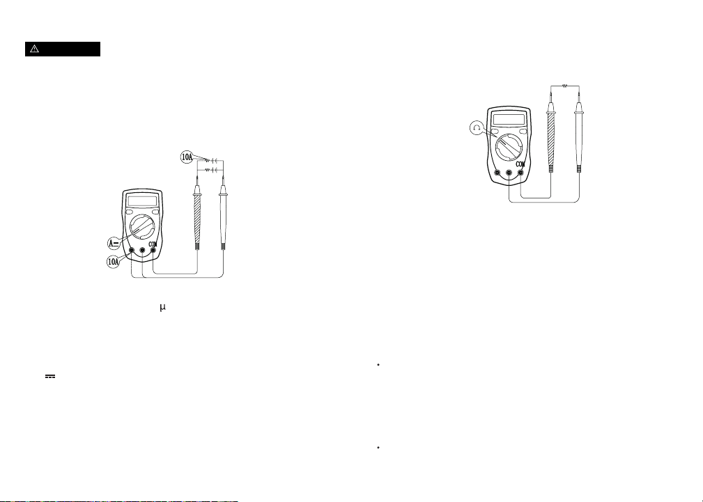
DC Current Ranges: 2000
A, 20mA, 200mA, 10A
1. Turn off the power to the circuit and discharge all high-
voltage capacitors.
2. Plug the red test lead into the VΩmA or 10A terminal,
then plug the black test lead into the COM terminal.
3. Set the rotary switch to the appropriate measurement in
A
range.
4. Break the current path to be tested.
5. Connect the red test lead to the most positive side of the
break and the black test lead to the most negative side of
the break.
6. Turn on the circuit power.
7. When measurement is completed, disconnect the test
leads from the object of measurement.
Figure 3
Figure 4
Resistance Ranges: 200Ω, 2000Ω, 20kΩ, 200kΩ, 20MΩ,
200MΩ
1. Plug the red test lead into the VΩmA terminal, then plug
the black test lead into the COM terminal.
2. Set the rotary switch to the appropriate measurement in
Ω range.
3. Connect the test leads to the object of measurement, the
measured value will appear on the display.
4. When measurement is completed, disconnect the test
leads from the object of measurement.
NOTE
The test leads can add 0.1Ω to 0.3Ω of error to the
resistance measurement. To obtain precise readings in low-
resistance measurement (200Ω), short-circuit the input
terminals beforehand and record the reading obtained
(reading X). This is the additional resistance from the test
lead. Then use the equation:
Measured resistance value (Y) - (X) = resistance result
For high-resistance measurements (>1MΩ), it may take a
few seconds for the reading result to stabilize.
DC Current Measurement
Never attempt an in-circuit current measurement where the
voltage between the terminals and ground is greater than
60V. If the fuse burns out during measurement, this may
cause harm to the user and/or damage to the device. Use
proper terminals, functions, and range for measurement.
When the testing leads are connected to the current
terminals, do not parallel them across any circuit.
Resistance Measurement
WARNING
NOTE
If the value of voltage is unknown, use the maximum
measurement position (10A) and reduce the range until
proper readings are obtained.
Loading ...
Loading ...