Loading ...
Loading ...
Loading ...
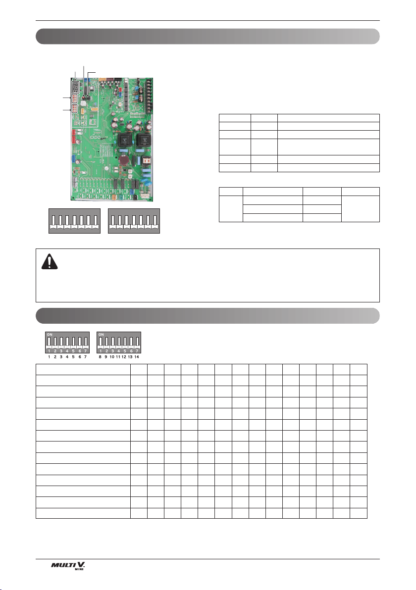
Electrical Wiring
48 Outside Unit
1234567891011121314
Short Pipe Length
Long Pipe Length
Refrigerant Auto Charging
Refrigerant Checking
Cool/Heat Selector
Snow (Heat Pump model)
Forced Defrosting (Heat Pump model)
Snow + Forced Defrosting (Heat Pump model)
Night Silent Operation
Pump Down
Pump Out (Heat Pump model)
Forced Oil Return
Vacuum Mode
l5
5l
ll l
ll l l
ll5
5l5
55l
5ll
ll
l5
ll
55 l
ll
Location of DIP Switch
Configuration of DIP Switch
SW01B
1234567
ON
SW02B
<Initial shipping condition of DIP Switch>
1234567
ON
Main PCB
SW01B
(DIP S/W)
SW02B
(DIP S/W)
7 - Segment
SW02V
Auto addressing
SW01V
Data confirm
SW01B SW02B
1.
When outdoor unit is powered on after configuring the DIP switch, prop-
er input of configuration value can be verified through 7-Segment.
2.
This function is shown only for 2 seconds after turning on the power.
n Verification of outdoor unit configuration
- After power is turned on, number are shown on
7-Segment consecutively
- These numbers show the configuration status
Model Code
In case of 1Φ, 5HP(48kBtu/h) model
Seqence NO. Content
1 121 Model code, 1~255
2 5 Total capacity (HP)
32
2 : heatpump
No display : cooling only
4 25 Normal
5 122 Model type, 1~255
WARNING
•
Main PCB power should be reset in order to recognize the changed function after handling the DIP switch for configuration of additional functions.
•
Main PCB power should be reset after resetting the DIP switch for cancellation of additional function
•
Please configure DIP switch properly. Otherwise, It can overstrain product during operation
4(36) 120
5(48) 121
6(53) 122
Phase Capacity(HP,kBtu/h) Model code Model type
1ø
122
Loading ...
Loading ...
Loading ...