15‐W06,50‐SHW06,50‐SHW06L,
50‐TRW06
INSTALLATION&OPERATION
MANUAL
CAUTION
Pleasereadthisentiremanualbeforeinstallationanduseofthiswood
fuel‐
burning
appliance. Keepchildren,furniture,fixturesandallcombustibles
away
from
anyheating
appliance.
SAVETHESEINSTRUCTIO NS
SAFETY
NOTICE
Failuretofollowtheseinstructionscanresultinpropertydamage,bodily
injury
orevendeath. Foryoursafetyandprotection,followthe
installation
instructionsoutlined
inthismanual. Contactyourlocalbuildingorfire
officials
aboutrestrictionsand
installationinspectionrequirements(including
permits)
inyour
area.
PFSFileNumber
20‐607
Rev10/2020
THISWOODHEATERNEEDSPERIODICINSPECTIONANDREPAIRFORPROPEROPERATION.
CONSULTTHEOWNER’SMANUALFORFURTHERINFORMATION.ITISAGAINSTFEDERAL
REGULATIONSTOOPERATETHISWOODHEATERINAMANNERINCONSISTENTWITHTHE
OPERATINGINSTRUCTIONSINTHEOWNER’SMANUAL.
Manufactured
By:
England’sStoveWorks,
Inc.
POBox
206
Monroe,VA
24574
www.heatredefined.com
Parts(800)516‐3636
Questions(800)245‐6489
Laversionfrançaisedecemanuelsuitlaversionanglaise.
Page | 2
IMPORTANT:IFYOUHAVE APROBLEMWITHTHISUNIT,DO
NOTRETURNITTOTHEDEALER. CONTACTTECHNICAL
SUPPORT@1‐800‐245‐6489
MobileHomeUse(ApprovedforU.S.ONLY):
Thisfreestandingwoodunitisapprovedformobilehomeor
doublewideinstallationwiththeoutsidecombustionairhook‐
up. Seethe“Installation”sectionofthismanualfordetails
pertainingtomobilehomeinstallations. Mobilehome
installationmustbeinaccordancewiththeManufactured
HomeandSafetyStandard(HUD),CFR3280,Part24.
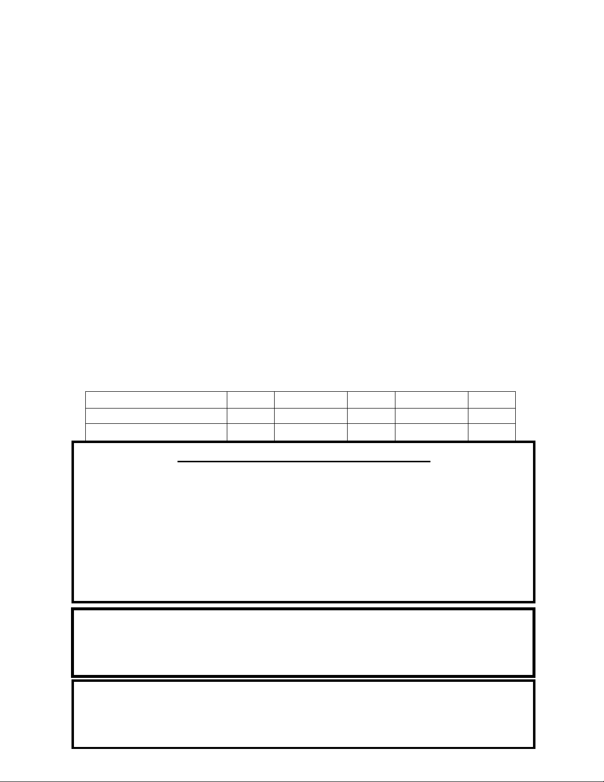
Retainforyour
files
Model
Number
Date
of
Purchase
Date
ofManufacture
Serial
Number
*Thisinformationcanbefoundonthesafetytagattachedtotherearoftheunit.
Havethisinformationon handifyouphonethefactoryoryourdealerregardingthis
product.
•
Keepchildrenaway.
CAUTION
•
Supervisechildreninthesameroomasthisappliance.
•
Alertchildrenandadultstothehazardsofhightemperatures.
•
DoNOToperatewithprotectivebarriersopenorremoved.
•
Hotwhileinoperation!Keepclothing,furniture,draperiesandother
combustiblesaway. Contactmaycauseskinburns!
DoNOTover‐fireyourunit.
•
InstallationMUSTcomplywithlocal,regional,stateandnationalcodesand
regulations.
•
Consultlocalbuilding,fireofficialsorauthoritieshavingjurisdictionabout
restrictions,installationinspection,andpermits.
Page | 3
WELCOME!
Introduction
•
ThankYou...................................4
Specifications
•
HeatingSpecifications..................5
•
Dimensions...................................5
•
EPACompliance...........................5
Installation
•
Installation
Overview
...................6
•
ClearancestoCombustibles.........7
•
VentingIntroduction....................8
•
VentingGuidelines.......................8
•
AdditionalVenting
Informatio n
...9
•
Wall
Pass
‐Throughs.....................10
•
ApprovedVentingMethods
o ThroughtheWall...........11
o ThroughtheCeiling........12
o MasonryChimney...........13
o MasonryFireplace..........14
•
MobileHomeInstallation...........15
•
OutsideAir
Hook‐Up
...................15
•
FloorProtection..........................16
Operation
•
Break‐InFires.............................17
•
ContinuousOperation...........17‐18
•
Safety
Notes
..........................19‐20
Maintenance
•
StoveMaintenance....................21
•
Inspecting
Gaskets
......................22
•
Finish..........................................22
Replacing Components
•
Glass...........................................23
•
BurnerTubes..............................24
•
CeramicFiberboard....................24
•
HeatShield…… … ……………...........24
Optional Accessories
•
AC‐16/AC‐30
Blower
..................25
ImportantInformation
EPAandSafetyInfo………………26
Troubleshooting Guide
•
Troubleshooting.........................31
Illustrated Parts Detail
•
PartsList.....................................32
•
BrickLayout................................33
Warranty
•
SampleTag..................................34
•
Warranty
Details
.........................35
•
ImportantNo
tice
.........................36
•
WarrantyregistrationForm........37
This manual is available for free download on the manufacturer’s web site. It is a copyrighted document and resale is
strictly prohibited. The manufacturer may update this manual occasionally and cannot be responsible for problems
including injuries or damages resulting from the use of information found in any manual from unauthorized sources.
PLEASE NOTE: If you purchased this model from certain stores, their model number may end in “L” “LC” “H” “CT”,
etc. This manual does apply to those models as well.
CAUTION:Stoveisheavy.
Inaddition,whenhandlinganysheetmetalproducts,beawarethattheremaybesharpedgesorburrs.
Althoughwemakeeveryefforttoeliminateanysharpedges,pleaseusecautionwhenhandlinganymetalparts.
Remembertodisconnect(unplug)thestovefromthepowersourceand
allowittocompletelycooldown
beforeperforminganymaintenance.
Page | 4
Thank you for purchasing this fine product from England’s Stove Works!
England's Stove Works was started, and is still owned by, a family that believes
strongly in a "Do It Yourself" spirit – that’s one reason you found this product at
your favorite “Do It Yourself” store.
We intentionally design and build our stoves so that any homeowner can maintain
his or her unit with basic tools, and we're always more than happy to show you
how to do the job as easily and as inexpensively as possible.
From our free, downloadable service sheets to our "wizard-style," click-through
Troubleshooting guide on our web site, we have always tried to help our customers
stay "heat-ready," especially when oil and electricity prices continue to skyrocket.
Please look at our vast Help section on our web site and call our Technical Support
department at (800) 245-6489 if you need any help with your unit. We are nearly
always able to help “walk you through” any repairs, problems or questions you
may have.
PLEASE NOTE: While information obtained on our web site and through our 800
number is always free of charge, there will be a service charge incurred with any
“on-site” repairs or maintenance that we may arrange.
Wishing you years of efficient, quality and “comfy” heating,
England’s Stove Works
Technical Support Department
www.HeatRedefined.com
(800) 245-6489
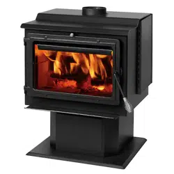
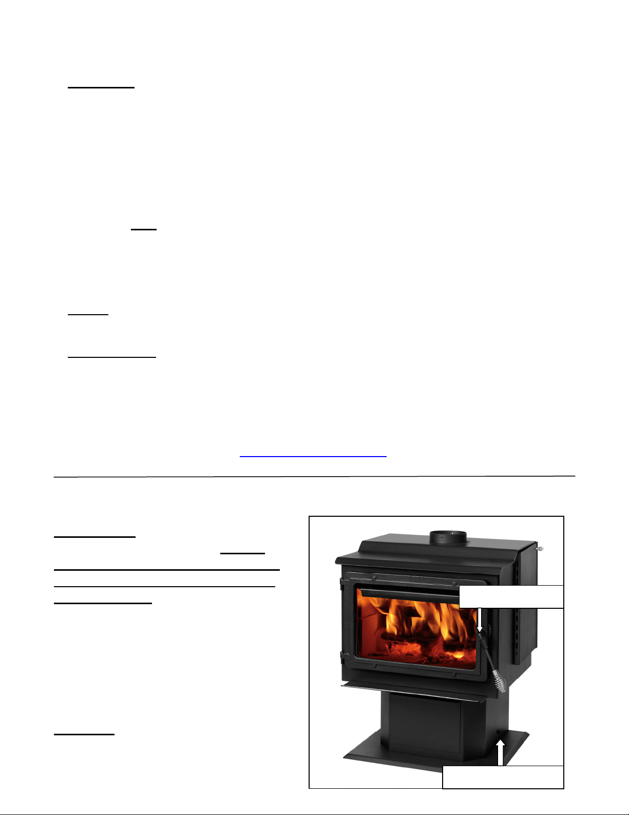
REMOVABLE DOOR HANDLE
Please Note: This unit comes with a
removable door handle, which
must be removed from the stove
when not being used to open or
close the door.
To use the handle, simply place it
onto the door handle rod that is
located on the stove door.
The handle may then be stored in
the hole that is located on the right
side of the pedestal when not in
use.
CAUTION – Handle will get HOT if left
on stove.
DoorHandleRod
HandleStorageHole
Page | 5
SPECIFICATIONS
Heating Specificatio ns
•
MaximumBurnTime**
.............................................................................Upto14
hours
•
ApproximateSquareFootageHeated***
...............................................
2,400sq.ft.
•
FlueCollar
.................................................................................................
6.0in.round
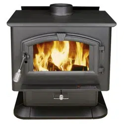
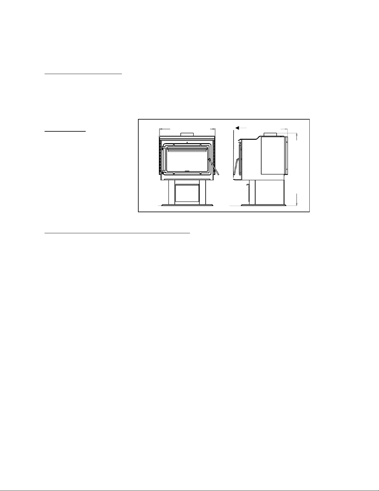
Dimensions(Inches)
Dimensionsareapproximate.Besuretolocateyourstoveintheinstallationareabeforeinstallingpipe,etc.
EPA and Safety Compliance Specifications
EPAComplianceStatus…….................Certifiedtocomplywith2020particulateemission
standardsusingcordwood.
EPATestStandard………………………………….ASTME3053‐17,EPAAlt125,CSAB415.1‐10
•
Particulate
Emissions............................................................................1.8
grams/hr
COEmissions……………………………………………………………………..………….1.9grams/min
HeatOutputRange…………………………………………….……………………..17500–65900Btu/hr
•
Efficiency*
...................................................................................................72%HHV
CertifiedTo…………………………………………UL1482‐2011(R2015)andULC‐S627‐00(R2016)
**‐Maximumburntimesareheavilydependentonthetypeofwoodburnedinthestove;assuch,thesenumbers
mayvary.
***‐Themaximumheatingcapacityofthisunitcanvarygreatlybasedonclimate,constructionstyle,insulation
andamyriadofotherfactors.Usethisinformationinconjunctionwith
aBTUlosscalculationforyourhometo
determineifthisunitwillbesufficientforyourneeds.
TAMPERWARNING:“Thiswoodheaterhasamanufacturer‐setminimumlowburnratethat
mustnotbealtered.Itisagainstfederalregulationstoalterthissettingorotherwise
operatethiswoodheaterinamannerinconsistentwithoperatinginstructionsinthis
manual.”
“Thiswoodheaterneedsperiodicinspectionandrepairforproperoperation.Itisagainst
federalregulationstooperatethiswoodheaterinamannerinconsistentwithoperating
instructionsinthismanual.”
34
1
/
4
35
3
/
4
27
3
/
8
23
3
/
4
36‐in.High
26‐in.Deep
27‐in.Wide

Page | 6
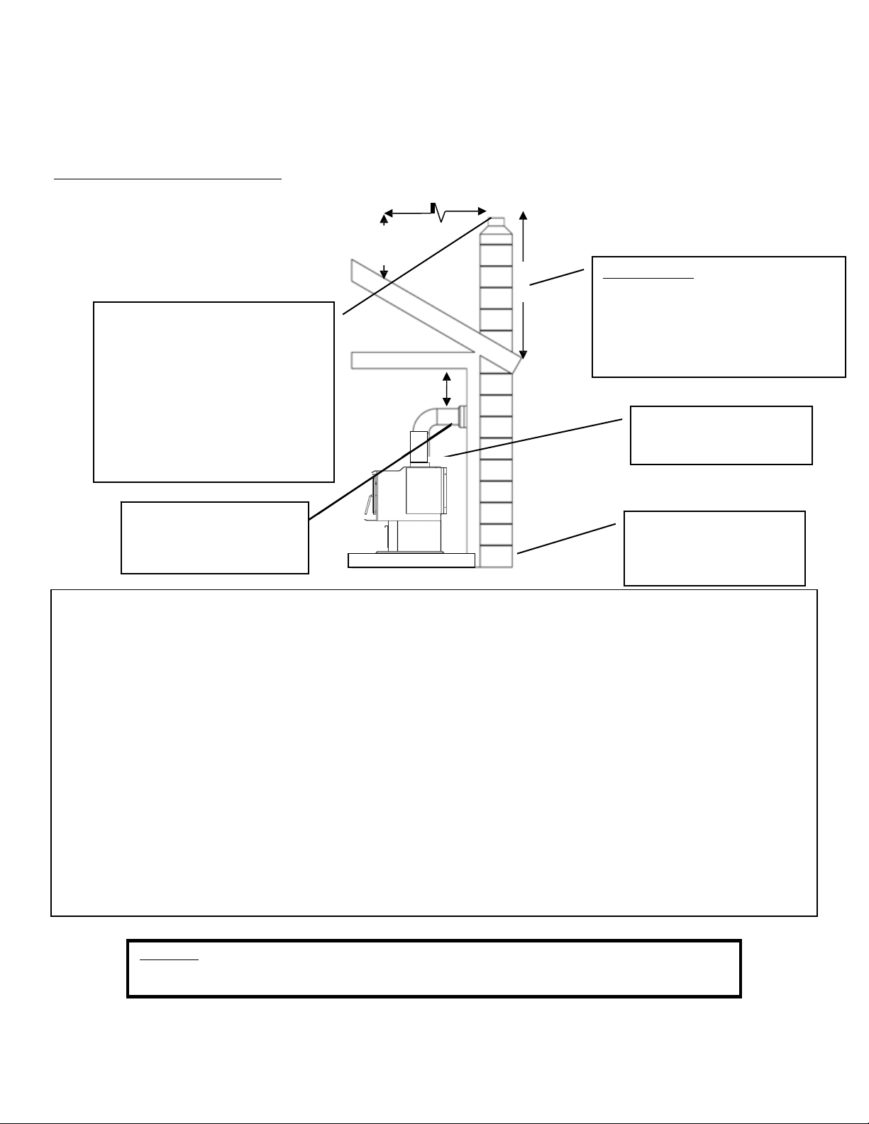
INSTALLATION
Installation Overview
Whenchoosingalocationforyournewstove,thereareamultitudeoffactorsthat
shouldbetakenintoaccountbeforebeginningtheinstallation.
1.TrafficPatterns–Tohelppreventaccidents,thestoveshouldbeplacedinalocation
whereitisoutofthewayofnormaltravelthroughthehome.
2.HeatFlowandEfficiency–Whendecidingonalocationforthestove,consider the
wayheatmovesthroughoutyourhome.Installthestovewhereyouneedtheheat;
basementinstallationsoftendonotallowsufficientheattoflowtotheupper floors
andatopfloorinstallationwillnotallowanyheattoreachthefloorsbelow. Always
considerthatheatrisesandwilltakethepathofleastresistancewhileitisstillhot.
3.ExhaustLocation–Theenginewhichdrivesawoodstoveisthechimneysystem,so
itisimportanttoconsiderpreciselyhowthechimneysystemwillbeintegratedinto
thestoveinstallation. Ideally,awoodstovechimneywillruncompletelyvertical
fromthefluecollaroftheunitallthewaytotheterminationpointabovetheroof
line. Keepingtheentirechimneysysteminsidetheheatedenvelopeofthehome
willensureastrong,easytoinitiatedraftinthechimney. Althoughexteriorchimney
systemsoftenfunctionproperly,theyaremorelikelytosufferfromcolddowndrafts
atstartuporprovideweakdrafttotheunit. Also,considerthecross‐sectionalarea
ofthechimney;althoughexistingmasonrychimneyscanoftenbeused,alarge
externalmasonrychimneywillresultinaunitthatisdifficultorimpossibleto
operateproperly. Inthatcase,aninsulatedchimneylinerwilloftenberequiredto
supplythenecessarydraft.
4.WallConstruction–Locatingthestovesothattheexhaustsystemcanpassbetween
studswillsimplifytheinstallationandeliminatethe needtoreframeanysectionsof
thewallorceilingtoaccommodatethewallthimbleorceilingbox.
WARNING
•
Donotstoreorusegasolineorotherflammablevaporsandliquidsinthe
vicinityofthisoranyotherappliance.
•
DoNotOver‐fire–Ifanyexternalpartstartstoglow,youareover‐firing.
Reduceintakeairsupply. Over‐firingwillvoidyourwarranty.
•
Complywithallminimumclearancestocombustiblesasspecified.
Failureto complymayresultinahousefire.
•
Testedandapprovedforcordwoodonly. Burninganyotherfuelwill
voidyourwarranty.
Page | 7
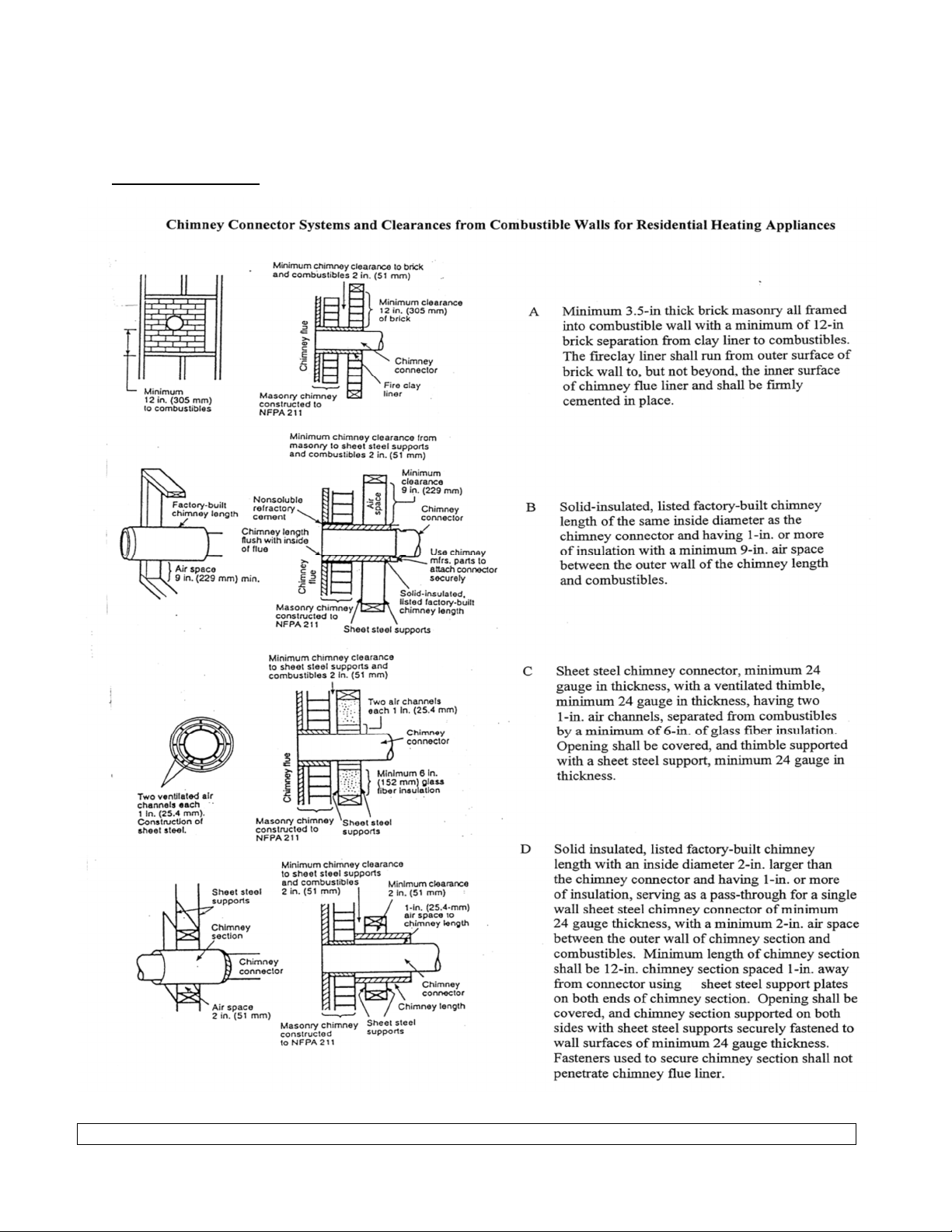
INSTALLATION
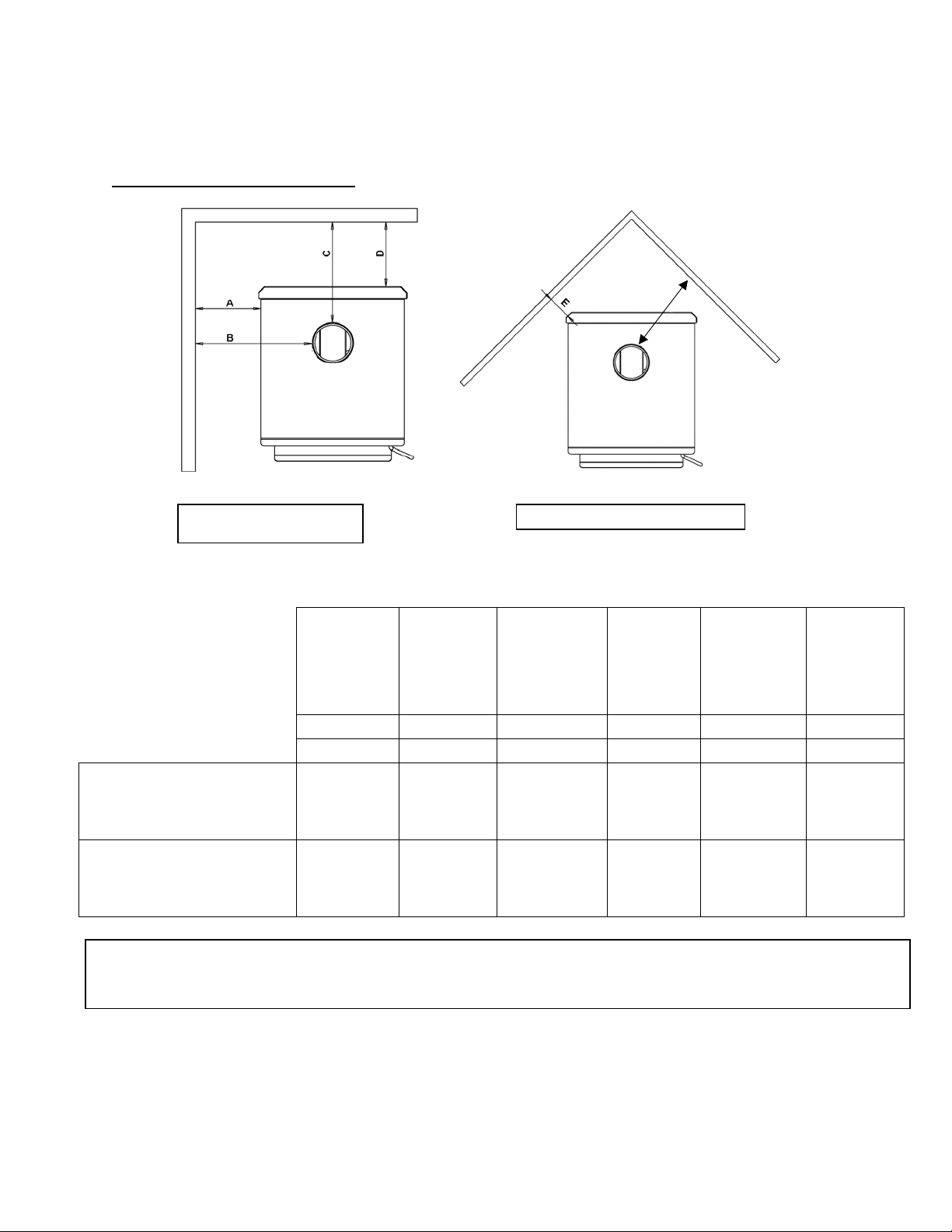
Clearances to Combustibles
Parallel
Wall
Installation
CornerInstallation
WARNING‐INSTALLVENTATCLEARANCESSPECIFIEDBYTHEVENTMANUFACTURER
Unitto
Side
Wall
Chimney
Connector
to
Side
Wall
Chimney
Connector
to
Rear
Wall
Unit
to
Rear
Wall
Unitto
Corner
Chimney
Connector
to
Corner
A
B
C
D
E
F
in(cm)
in(cm)
in(cm)
in(cm)
in(cm)
in(cm)
SingleWall
Chimney
Connector
Unprotected
Surfacewithside
shields
19
(48.3)
30
(76.2)
12
(30.5)
6
(15.2)
5
(12.7)
17
(43.2)
DoubleWallChimney
ConnectorUnprotected
Surfacewithsideshields
19
(48.3)
30
(76.2)
12
(30.5)
6
(15.2)
5
(12.7)
17
(43.2)
Notesforthisunit:Theproductmaydifferslightlyfromthediagrams.Theclearancesaretheminimumforthisunitandmay
needtobeincreasedforblowerinstallationortohaveproperventilationclearances.
Observeallventilationmanufacturerclearancesandlocalcodes.
F
Page | 8
Venting Introduction
INSTALLATION
Venting Guidelines
Thiswoodstoveoperatesona
naturaldraftsystem,inwhichthechimney
systempullsairthroughthestove. Thisunit
mustbeinstalledinaccordancewiththe
followingdetaileddescriptionsofventing
techniques;notinstallingthestovein
accordancewiththedetailslistedherecan
resultinpoorstoveperformance,property
damage,bodilyinjuryordeath. Avoid
make‐shiftcompromiseswheninstallingthe
ventingsystem. England’sStoveWorksis
notresponsibleforanydamageincurred
duetoapoororunsafeinstallation.
Becertainthatallaspectsofthe
ventingsystemareinstalledtotheventing
manufacturer’sinstructions,particularlythe
requiredclearancestocombustibles. Also,
becertaintouseanatticradiationshieldto
preventinsulationfromcontactinga
chimneywhichpassesthroughanattic.
Thechimneysystemisthe“engine”
whichdrivesawoodstove,soitis
imperativeforproperunitfunctionthatthe
ventingsystembeinstalledexactlyas
describedinthefollowing section.
Ifquestionsarisepertainingtothe
safeinstallationofthestove,ourTechnical
Supportline(800‐245‐6489)isavailable.
Contactyourlocalcodeofficialtobecertain
yourinstallationmeetslocalandnational
firecodes,andifyou’reuncertainabout
howto safelyinstall thestove,we strongly
recommendcontactingalocal NFIcertified
installertoperformtheinstallation.
•
ALWAYSinstallventpipeinstrict
adherencetotheinstructionsand
clearancesincludedwithyour
ventingsystem.
•
DONOTCONNECTTHISUNITTOA
CHIMNEYFLUESERVINGANOTHER
APPLIANCE.
•
DONOTinstallafluepipedamper
oranyotherrestrictivedeviceinthe
exhaustventingsystemofthisunit.
•
USEanapprovedwallthimblewhen
passingandaceilingsupport/fire
stopwhenpassingthroughaceiling.
•
INSTALLthreesheetmetalscrewsat
everychimneyconnectorjoint.
•
AVOIDexcessivehorizontalrunsand
elbows,asbothwillreducethedraft
of the venting systemand will result
inpoorstoveperformance.
•
INSPECTyourventingsystemoften,
tobecertainitisclearofcreosote,
fly‐ashandotherrestrictions.
•
CLEANtheventingsystemas
detailedinthemaintenancesection
ofthismanual.
•
ADHEREtothe10‐3‐2ruleregarding
chimneyterminations.
•
INSTALLsinglewallchimney
connectorwiththemaleenddown
topreventcreosoteleakage. Follow
doublewallchimneyconnector
manufacturer’sinstructions
regardingproperpipeinstallation.
WARNING:VentingsystemsurfacesgetHOT,andcancauseburnsif
touched. Noncombustibleshielding orguardsmayberequired.
Where passage through a wall or partition of combustible construction is desired, the
installation shall conform with CAN/CSA-B365.
Page | 9
FlueGasDirection
Additional Venting Information
INSTALLATION
•
Donotmixandmatchcomponentsfromdifferentpipemanufacturerswhenassembling
yourventingsystem(i.e.DoNOTuseventingpipefromonemanufacturerandathimble
fromanother).
•
Werequireaminimumchimneyheightof15.0ft. Chimneysystemsshorterthanthis
maynotcreatetheamountofdraftwhichisrequiredtooperatethiswoodburningunit.
•
Donotusemakeshiftcompromiseswheninstallingtheventingsystem;haveexisting
chimneysystemsinspectedbeforeuseandbecertainallnewchimneysystemsare
installedtothemanufacturer’sspecificationsandwithonlyULlistedcomponents(ULCif
Canada).
•
Prefabricatedventingsystemsusedforthisstovemustbe listedtoULCS629(Canada)
andUL103HT(US).
•
Neverinstalladraftinduceroranyothersystemwhichincreasesthenaturaldraftofthe
chimney;similarly,donotinstallabarometricorstovepipedamperwiththisunit.
•
Neverusesinglewallordoublechimneyconnectorasachimneysystem;neverpass
eithertypeofchimneyconnectorthroughacombustiblewallwithoutcarefullyfollowing
themanufacturer’sinstructions andthose listedinthefollowingpageonWallPass‐
Throughs.NEVERpasschimneyconnectorthroughanattic,floor,closetorroof.
•
Onlyuse24gaugeMSGblacksinglewallchimneyconnectororULListed(ULCifCanada)
doublewallchimneyconnector.
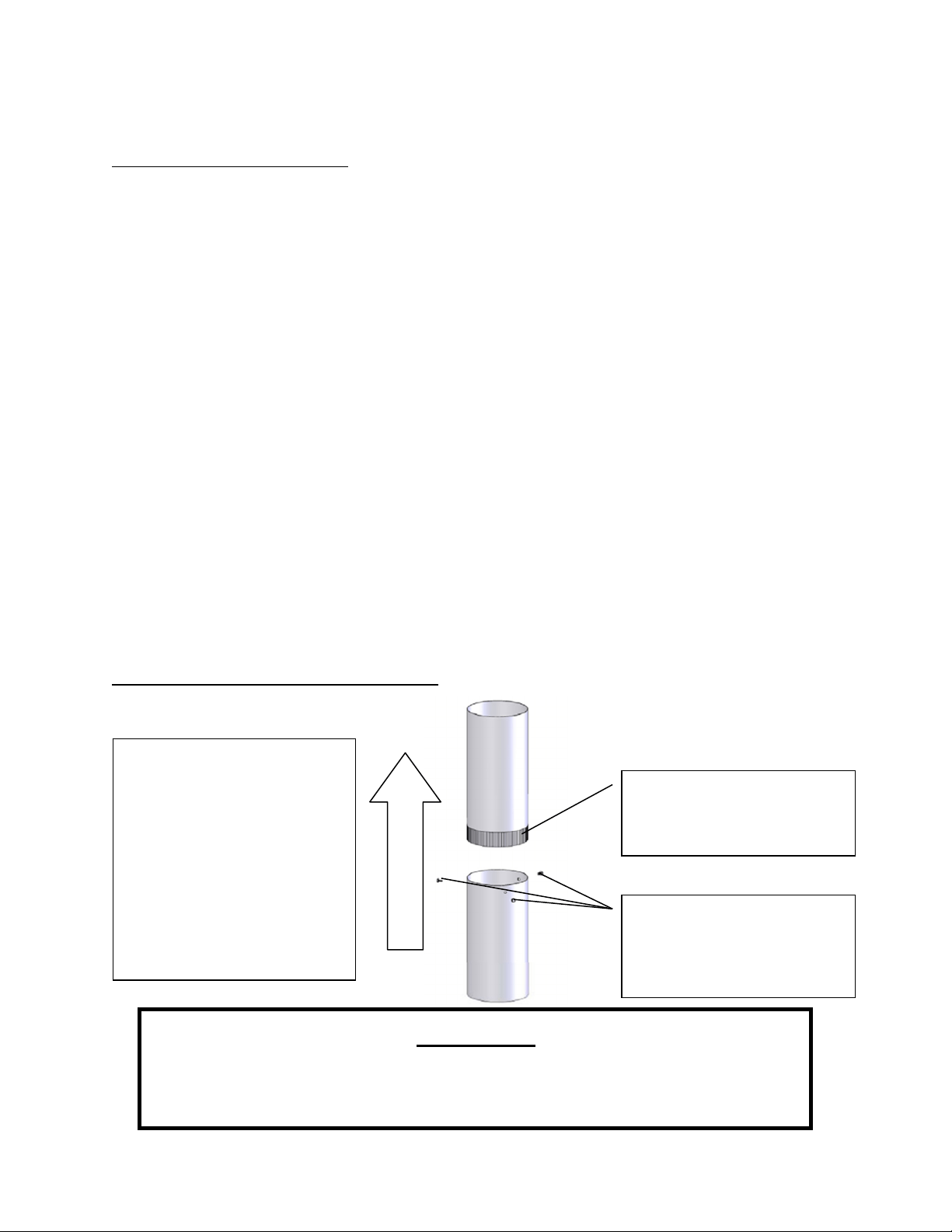
Single Wall Chimney Connector Installation
Themaleendofsinglewall
chimneyconnectoris
installedfacingdownsothat
anyliquidcreosoteinthe
fluewillrunintotheunit
insteadofontotheoutside
ofthepipe(thenaturaldraft
inthechimneysystemwill
preventsmokeleakageat
thejoints).
Crimpedormaleendof
singlewallchimney
connectormustfacedown.
Fasteneachsinglewall
chimneyconnectorjoint
withthreesheetmetal
screws.
WARNING
•
INSTALLVENTATCLEARANCESSPECIFIEDBYTHEVENTMANUFACTURER.
•
HOT!Donottouch! Severeburnsorclothingignitionmayresult.
•
Glassandothersurfacesarehotduringoperation.
INSTALLATION
Wall
Pass-Throughs
In
Canada
, the
installation
must
conform
to CAN/CSA-8365 when passing through
combustible
construction.
Page
10
Page | 11
18.0in.
2.0ft.
3.0ft.
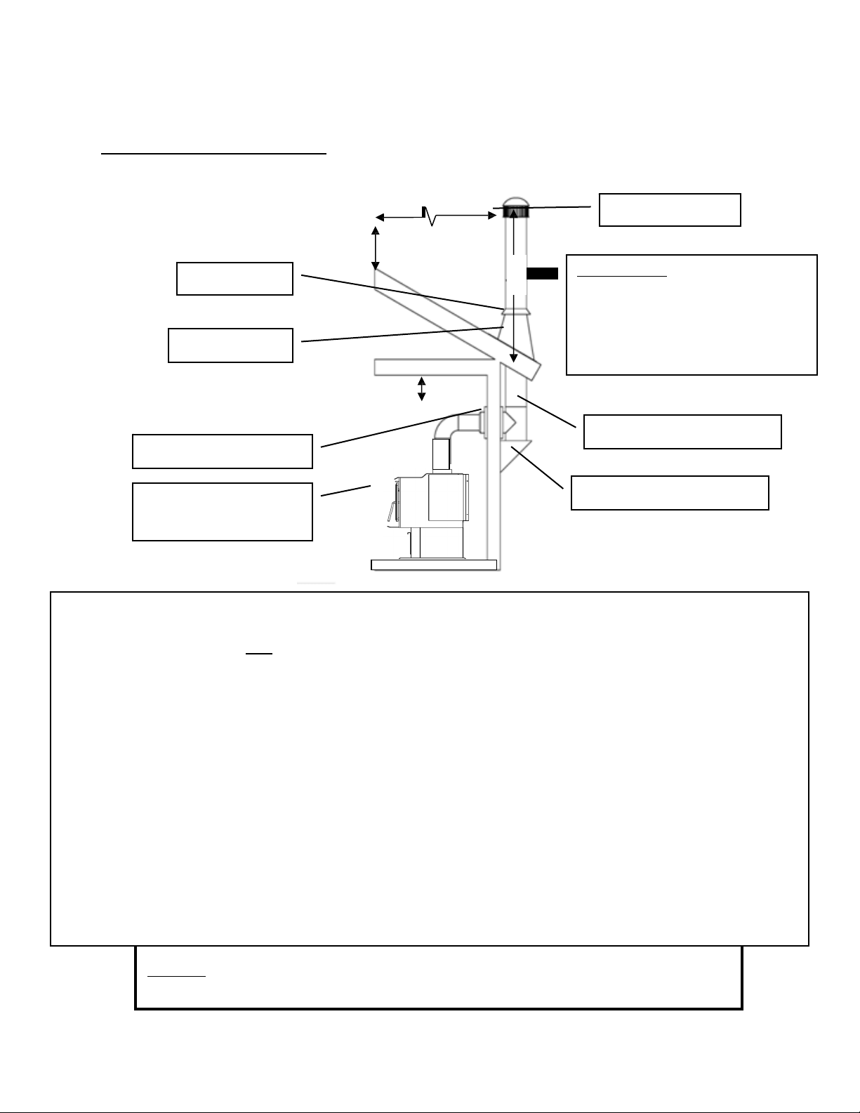
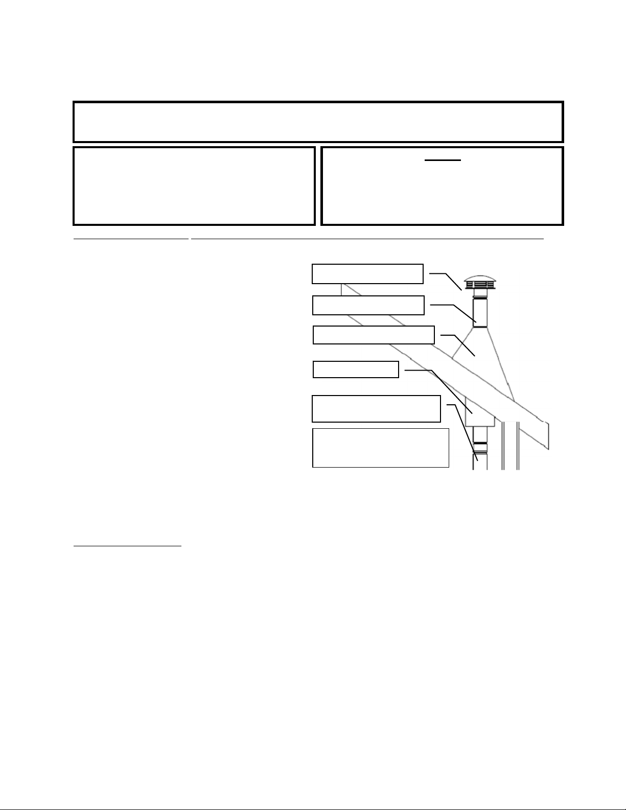
INSTALLATION
Approved Venting Method 1:ThroughtheWallFactoryBuiltChimney
10
ft.
TerminationCap
StormCollar
RoofFlashing
The 10‐3‐2 Rule:Thechimneysystem
mustterminate3.0ft.abovethepoint
whereitscenterlinepassesthroughthe
roofANDthechimneymustterminate
2.0ft.aboveanypartofthedwelling
withina10ft.radiusofthechimney.
WallThimble
ClassAChimneySystem
ChimneyConnector
(SingleorDoubleWall)
TeeandTeeSupport
•
PrefabricatedchimneysystemsmustconformtoUL‐103HT(2100°F)fortheU.S.andULC‐S629(650°C)for
Canada.
•
Thiswoodbu rningunitisonlylistedforinstallationwith6.0”diameterchimneyconnectorandchimneysystems.
Installingthisunitonprefabricatedchimneyslargerthan6.0”diameterwillresultindecreaseddraftandthe
potentialforpoorunitperformance.
•
Followallventingsystemmanufacturer’sinstallationrequirementsandrequiredclearances .
•
Usethreesheetmetalscrewsateachsinglewallchimneyconnectorjoint(checkmanufacturer’s
recommendationswhendoublewallchimneyconnectorisused).
•
Drillthreeholesinthefluecollaroftheunitandattachthechimneyconnectortotheunitusingsheetmetal
screws(holesshouldbepre‐drilledinfluecollarfromfactory).
•
Properlyattachtheprefabricatedchimneysystemtothehomeinstrictaccordancewiththeprefabricated
chimneysystemmanufacturer’sinstructions.
•
Avoidnumerouselbowsandexcessivehorizontalrunsasbothwillleadtopoordraftandincreasedcreosote
accumulation. Horizontalrunsofchimneyconnectormustneverexceed4.0ft.andtheoveralllengthofthe
chimneyconnectormustnotexceed8.0ft.withsinglewallblackconnectorpipe.Ifnecessaryto
runlonger
than8.0ft.ofchimneyconnector pipe,doublewallblackchimneyconnectorpipemustbeused.
•
Specialadaptersandslipconnectorsareavailabletoeliminatetheneedtocutsinglewallchimneyconnector.
Doublewallchimneyconnectormustbeusedwiththeseslipconnectors,asitcannotbetrimmedtolength.
Please Note:Installationdiagramsareforreferencepurposesonlyandarenotdrawntoscale,normeanttobeusedasplans
foreachindividualinstallation. Pleasefollowallventingsystemrequirements,maintaintherequiredclearancesto
combustibles,andfollowalllocalcodes.
Page | 12
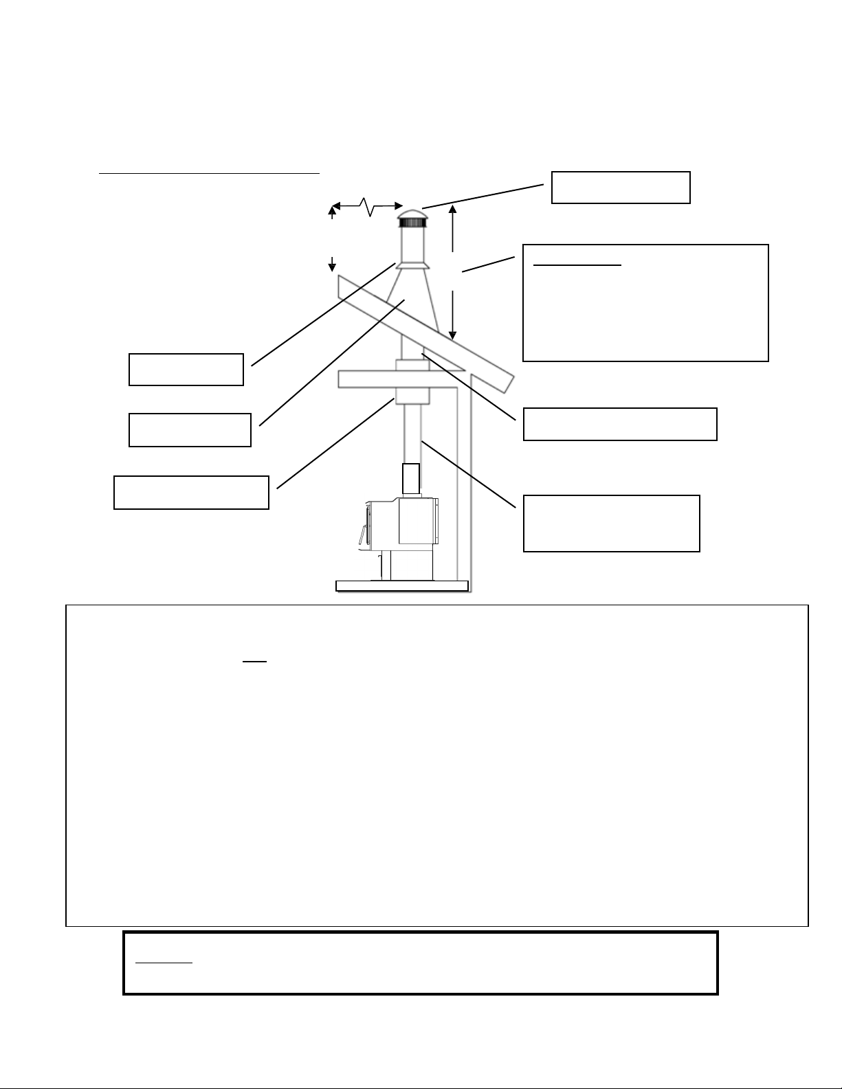
2.0ft.
3.0ft.
INSTALLATION
Approved Venting Method 2:ThroughtheCeiling
10
ft.
TerminationCap
StormCollar
The 10‐3‐2 Rule:Thechimneysystem
mustterminate3.0ft.abovethepoint
whereitscenterlinepassesthroughthe
roofANDthechimneymustterminate
2.0ft.aboveanypartofthedwelling
withina10ft.radiusofthechimney.
RoofFlashing
ClassAChimneySystem
CeilingSupportBox
ChimneyConnector
(SingleorDoubleWall)
•
PrefabricatedchimneysystemsmustconformtoUL‐103HT(2100°F)fortheU.S.andULC‐S629(650°C)for
Canada.
•
Thiswoodburningunitisonlylistedforinstallationwith6.0”diameterchimneyconnectorandchimneysystems.
Installingthisunitonprefabricatedchimneyslargerthan6.0”diameterwillresultindecreaseddraftandthepotentialfor
poorunitperformance.
•
Followallventingsystemmanufacturer’sinstallationrequirementsandrequiredclearances.
•
Usethreesheetmetalscrewsateachsinglewallchimneyconnectorjoint(checkmanufacturer’s
recommendationswhendoublewallchimneyconnectorisused).
•
Drillthreeholesinthefluecollaroftheunitandattachthechimneyconnectortotheunitusingsheetmetalscrews
(holesshouldbepre‐drilledinfluecollarfromfactory).
•
Properlyattachtheprefabricatedchimneysystemtothehomeinstrictaccordancewiththeprefabricatedchimney
systemmanufacturer’sinstructions.
•
Theoveralllengthofthechimneyconnectormustnotexceed8.0ft. Inthecaseofcathedralceilings,the
prefabricatedchimneysystemshouldextendto8.0ft.fromthetopoftheunitifusingsinglewallchimney
connectorpipe.Ifnecessarytorunlongerthan8.0ft.ofchimney
connectorpipe,doublewallblackchimney
connectorpipemustbeused.
•
Specialadaptersandslipconnectorsareavailabletoeliminatetheneedtocutsinglewallchimneyconnector.
Doublewallchimneyconnectormustbeusedwiththeseslipconnectors,asitcannotbetrimmedtolength.
Please Note:Installationdiagramsareforreferencepurposesonlyandarenotdrawntoscale,normeanttobeusedasplans
foreachindividualinstallation. Pleasefollowallventingsystemrequirements,maintaintherequiredclearancesto
combustibles,andfollowalllocalcodes
Page | 13
2.0ft.
18.0in.
3.0ft.
INSTALLATION
Approved Venting Method 3:InternalorExternalMasonryChimneySystem
10
ft.
Chimneylinercross‐sectional
area(LengthxWidth)must
be
nolargerthantwicethecross‐
sectionalareaofthefluecollar
(2x28.27in
2
=56.55in
2
). If
chimneylinerislargerthan
56.55in
2
,reliningwitha5.5”
or6.0”linerisrequired
The10‐3‐2Rule:Thechimneysystem
mustterminate3.0ft.abovethepoint
whereitscenterlinepassesthroughthe
roofANDthechimneymustterminate
2.0ft.aboveanypartofthedwelling
withina10ft.radiusofthechimney.
ChimneyConnector
(SingleorDoubleWall)
MasonryThimblewith
propercle aranceto
combustibles
AshCleanoutsmust
haveanairtightsealto
preventweakdraft.
•
Followtheruleslistedaboveconcerningmaximumpermissiblefluelinersize;installingthisunitonmasonrychimneys
exceeding56.55in
2
incross‐sectionalareawillresultindecreaseddraftandthepotentialforpoorunitperformance.
•
Usethreesheetmetalscrewsateachsinglewallchimneyconnectorjoint(checkmanufacturer’s
recommendationswhendoublewallchimneyconnectorisused).
•
Drill threeholesinthefluecollaroftheunitandattachthechimneyconnectortotheunitusingsheetmetal
screws(holesshouldbepre‐drilledinfluecollarfromfactory).
•
Avoid numerous elbows and excessive horizontal runs as both will lead to poor draft and increased creosote
accumulation. Horizontal runs of chimney connector must never exceed 4.0 ft. and the overall length of the
chimneyconnectormustnotexceed8.0ft.withsinglewallblackconnectorpipe.Ifnecessaryto
runlongerthan
8.0ft.ofchimneyconnectorpipe,doublewallblackchimneyconnectorpipemustbeused.
•
Atightsealatthethimbleiscrucialforproperunitperformanceandtocreateasafeinstallation. Usetheproper
adapterdesignedforconnectingsingleordoublewallchimneyconnectortoamasonrythimble.
•
Haveexistingmasonrychimneysinspectedforsafetyandproperclearancestocombustiblesbeforeputtingtheminto
service;aqualifiedchimneysweepcanperformthisinspection.
•
Externalmasonrychimneysoftensuffercolddowndraftsandpoordraftperformanceevenwhentheymeetthe
cross‐sectionalarearules. Inthiscase,a6.0”insulatedlinermaybenecessary.
Please Note:Installationdiagramsareforreferencepurposesonlyandarenotdrawntoscale,normeanttobeusedasplans
foreachindividualinstallation. Pleasefollowallventingsystemrequirements,maintaintherequiredclearancesto
combustibles,andfollowalllocalcodes.
Page | 14
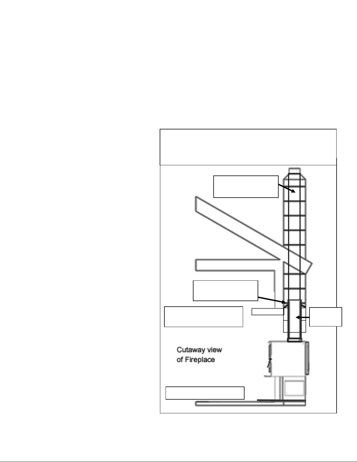
INSTALLATION
INSTALLATION INTO A MASONRY FIREPLACE
Preparation
Keep in mind that this type of a installation will make it difficult to change speeds on the blower frequently. We
recommend picking a blower speed and sticking with it, since adjusting the blower will be difficult because of
the tight installation. WARNING: DO NOT ATTEMPT TO ADJUST BLOWER DURING OPERATION. SKIN
BURNS MAY OCCUR WHEN MAKING CONTACT WITH THE UNIT. WAIT FOR UNIT TO COMPLETELY
COOL BEFORE ATTEMPTING TO ADJUST BLOWER.
Measure your hearth to ensure it is large enough to accept the unit.
Unit must have a 36” clearance from the top of the stove to a mantel in accordance with NFPA 211.
For the USA: Hearth must extend at least
16 in. from the front of the fuel opening.
For Canada: Hearth must extend at least 18 in.
(450.0 mm) from the front of the fuel opening.
Inspect your hearth to be sure it is
constructed of a noncombustible material
such as brick or stone. Do not install this
stove on a hearth that is constructed of
wood framework that is covered by brick or
stone and do not install this unit in a zero (0)
clearance fireplace. The manufacturer will
not be held responsible for an accident
resulting from this stove being installed on a
hearth constructed of a combustible
material.
Inspect your fireplace to ensure it is in
proper working order and free of any
obstructions.
Prior to installation, remove the existing
damper or wire it to fasten it open.
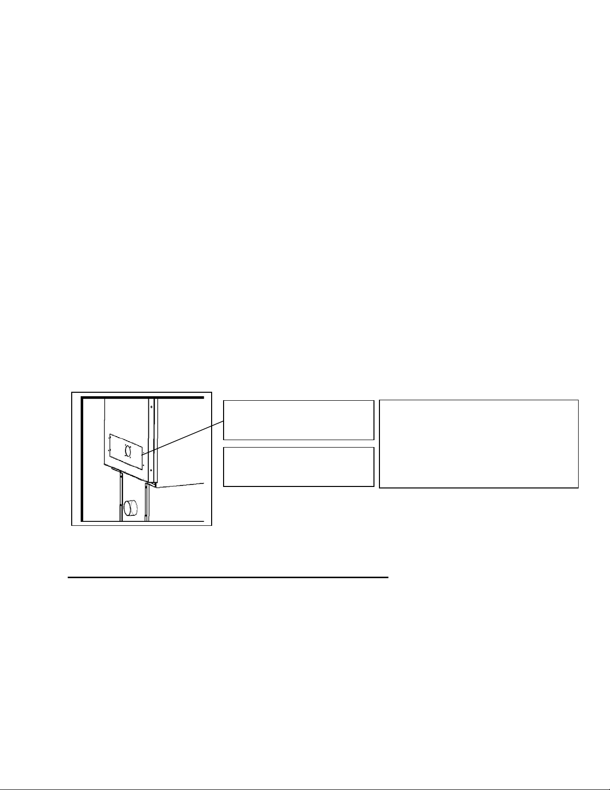
Venting Your Stove - Direct Connect
When this unit is direct connected it will
require six inch (6”) diameter 24 gauge pipe
from the stove through the damper opening.
(NOTE: The chimney connector must be
attached to the appliance with a minimum
of three (3) screws, and 3 screws should
be used to attach each adjoining
section.)
We highly recommend having the chimney
fully lined with a 6 inch liner to ensure proper
draft. This will make it necessary to block off
the open area on both sides of the pipe that
passes through the damper opening, which
can be done with sheet metal or by packing
flame retardant fiberglass insulation in the
open areas (no paper or combustibles).
You must be sure the draft from the chimney
is being pulled through the stove, and not
around the connector pipe.
We highly recommend you have this
done by a professional. You should also contact your local authorities to be sure you are following all codes.
36in.(91.4cm)minimum
Stovetoptomantel
Seehearthrequirements
Removeorwire
damperopen
6in.(15.24cm)liner
highlyrecommended
Connector
Pipe
The10‐3‐2Rule:Thechimneysystemmustterminate3.0ft.
abovethepointwhereitscenterlinepassesthroughtheroof
ANDthechimneymustterminate2.0ft.aboveanypartofthe
dwellingwithina10ft.radiusofthechimney.
Page | 15
INSTALLATION
WARNING
DONOTINSTALLINASLEEPINGROOM.
CAUTION
THESTRUCTURALINTEGRITYOFTHE
MANUFACTUREDHOMEFLOOR,WALL
AND
CEILING/ROOFMUSTBE
MAINTAINE
D.
Caution
NEVERdrawoutsidecombustionair
from:
Wall,floororceilingcavity
or
enclosedspacesuchasanattic,garageor
crawl
space.
Mobile Home Installation(U.S.ONLY,NOTAPPROVEDFORCANADIANMOBILEHOMEINSTALLATION)
•
ThewoodstoveMUSTbesecuredtothefloorofthemobilehomeusinglagboltsandtheholes
providedinthebottomoftheunitforthis
purpose.Outdoor‐airedspaceheaters
mustbeattachedtothestructure.Usea
#8copperwiretogroundstovetoframe
of
mobilehome.
•
Thewoodstovemustbeconnectedtothe
chimneysystemwithdoublewall chimney
connectorwhichisULlistedforusein
mobileandmanufacturedhomes.
•
Carefullyfollowallclearanceslistedinthe
appropriatesectionofthismanualANDfollow
theventingmanufacturer’s
minimum
clearance
requirements. Similarly,becertain
theventingsystemusedisapproved
formobile
homeuse.
•
Installationmustbeinaccordancewith
ManufacturersHome&SafetyStandard
ChimneyCap/SparkArrestor
ClassAChimneySystem
RoofFlashingandStormCollar
JoistShield/Firestop
MobileHomeApprovedDouble
WallChimney
Connector
Usesiliconetocreateavapor
barrierwherethechimneypasses
throughtoexterior.
(HUD)CFR3280,Part24aswellasanyapplicablelocalcodes.
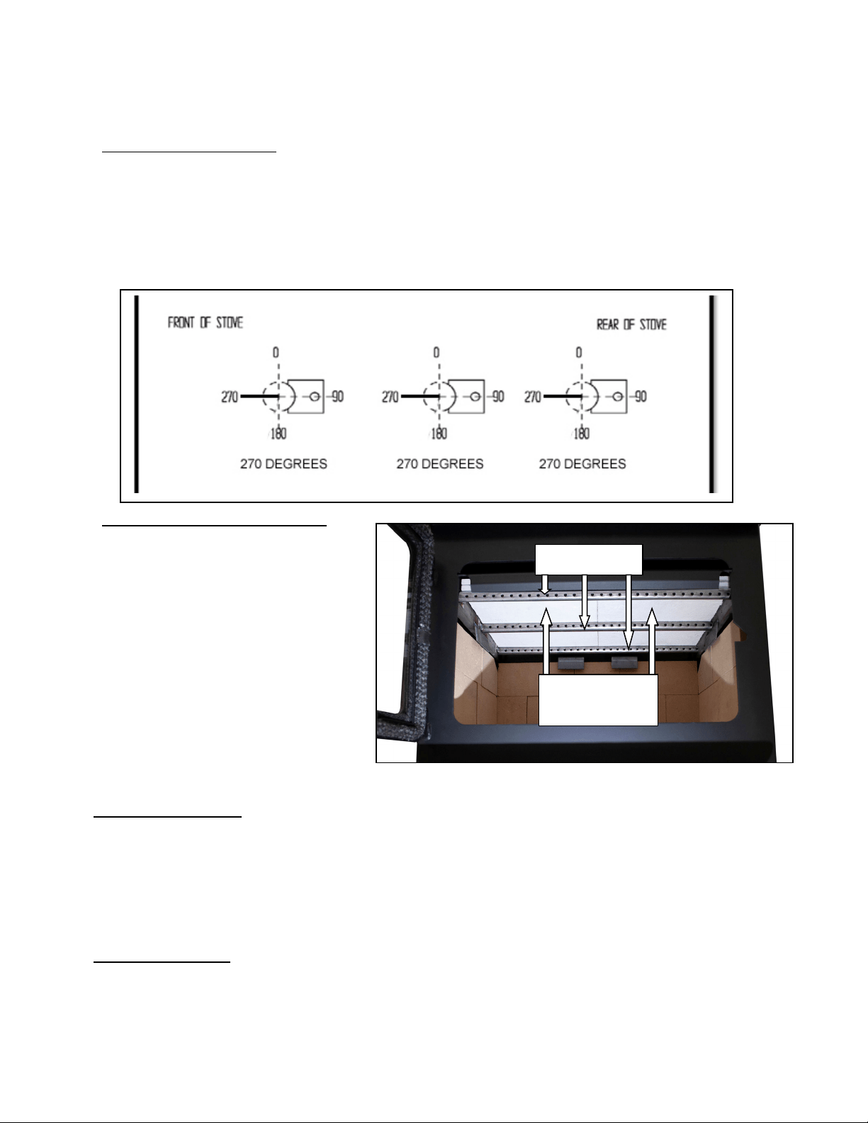
Outside Combustion Air
•
Theuseofoutsidecombustionairismandatorywheninstallingthiswoodstoveinamobileor
manufacturedhome.
•
Theoutsideairconnectionpipeprotrudesfromthebottomcenterofthestove;akitisavailable
fromEngland’ sStoveWorks,Inc.designedforconnectingthisunittooutsidecombustionair.[Part
No.AC‐OAK3]
•
IfitisnotfeasibletousetheAC‐OAK3outsideairhookup kitinyourstoveinstallation,other
materialsmaybeused,providedthefollowingrulesarefollowed:
o Thepipeusedforoutsideairhookupmustbemetal,withaminimumthicknessof.0209in.
(25gaugemildsteel)or
greaterandaninsidediameterofapproximately2.75in.
o Keeppiperunsshortanduseamechanicalfastenerateachpipejoint.
o Ascreenorotherprotectiondevicemustbefittedovertheoutsideairterminationpointto
preventrain,debrisandnuisanceanimalsfromenteringthepipingsystem.
Inspectthe
outsidecombustionairinletforblockanddebrismonthly.
Page | 16
FLOORPROTECTION
•
ThiswoodstoverequiresaU.L.listed(ULCifCanada)floorprotectorwithaRfactorofnolessthan
1.0,ifthestoveistobeinstalledonacombustiblefloor. Ifthefloorthestoveistobeinstalledon
isalreadynon‐combustible(i.e.aconcretefloo rinabasement),nofloorprotectionisneeded
(althoughadecor ativefloorprotectorcanstillbeusedforaestheticreasons).
•
Whenusinganyfloorprotector,consider thatthisstoveisnotonlyheavybutwillinduceheating
andcoolingcyclesonthefloorprotectorwhichcandamagetileandloosenmortarandgroutjoints
locatednearthestove.
•
ThefloorprotectorshouldbeULratedandlisted,orequivalent(ULCifCanada)andmustbe
noncombustible. AhearthrugisNOTanapprovedsubstituteforaproperhearthpad.
•
FortheUS:Thefloorprotectormustextendatleast16in.fromthefrontofthefuelopening,8in.
fromthesidesofthedooropeningand8in.fromtherearoftheunit.
•
ForCanada:Thefloorprotectormustextendatleast450mmfromthefrontofthefuel
opening,
200mmfromthesidesofthedooropeningand200mmfromtherearoftheunit.
•
Thefloorprotectormustextend2in.(50.8mm)oneithersideofanyhorizontalventingrunsand
extenddirectlyunderneathanyverticalventingpipe.
CAUTION
NEVERUSEGASOLINE,GASOLINE‐TYPELANTERNFUEL,KEROSENE,CHARCOALLIGHTER
FLUID,
ORSIMILARLIQUIDSTOSTARTOR“FRESHENUP”AFIREINTHISHEATER. KEEPALL
SUCH
LIQUIDSWELLAWAYFROMTHEHEATERWHILEINUSE. ADDITIONALLY,NEVERAPPLY
FIRE‐
STARTERTOANYHOTSURFACEOREMBERSINTHE
STOVE.
38½in
47in
_____
in
____in
A:US8in
CAN8in/200mm
B:US16in
CAN18in/450mm

Page | 17
OPERATION
Break‐In Fires
•
Thiswoodbu rningunitisconstructedofheavygaugesteelandcastironandisbuilttolastalong
time. However,inordertoensurenoexcessivethermalstressesareinducedonthe
metal
during
thefirstfire,threebreak‐infiresshouldbeburned,eachoneslightlyhotterthanthelast.
Thesebreak‐infireswillnotonlyhelpthestovebodyacclimatetothehightemperaturesofthe
fire,butwillalsoslowlycurethehightemperaturestovepaint,whichwillensurethe
high
qualityfinishlastsforyears.
WEHIGHLYRECOMMENDburningyourbreak‐infiresoutdoors,asthepaintand
manufacturingoilswill‘burnoff’thestoveexteriorsomewhatduringthistime.Ifyoudo
burnthemindoorswithyourfluesystem,opendoorsandwindowstoventilate.
•
Thisstovehasasingleaircontrolrodwhichregulatesthewoodburnrate;whentheprimaryair
controlslideispushedallthewayintotheunit,thestovewillburnmoreslowlyandputout
heatoveralongertimeperiod. Conversely,whentheaircontrolslideispulledallthewayout,
theunitwillburnmorequicklyandputoutalargeramountofheatoverarelatively shorter
time
period. Donotattempttomodifytherangeofaircontroladjustmentforanyreason.
•
Thefirstbreak‐infire shouldbejustalargekindlingfire,gettingthestovetoabout300°Fas
measuredbyamagneticthermometerontherightorleftsideofthestove,abovethe
door.
Once
thistemperatur ehasbeenreached,allowthefiretodieoutwiththeaircontrolopen.The
secondandthirdbreak‐infiresshouldbeabitlarger,withsomesmalldrysplitsaddedtothe
kindlingload. Thetemperaturegoalduringthesefiresisabout350°F–450°
F;don’tletthefire
gethotterth anthat.
ContinuousOperation–DailyOperationafteryourBreak‐InFires
Start‐up
- Loadthefireboxwithwood,splittomoderatesize.
- Ontopofthestartupwood,adddrykindlingsplitintoverysmallpieces.
- Ignitethekindlingfromthetopuntilaflameisestablished.
- ClosethedoorandsetthedampertoHigh(fullyopen)
toreducetheamountofsmoke.
HighBurn
- Besurethedogboxisnotcoveredwithashesorcoals(seeBrickLayout,page33,fordogbox
location).
- Loadwoodloadontothecoalbedafterchoppingandpackingcoals,ifnecessary.
- Closethedoor,set
thedampertoHigh(fullyopen)andsetblowertoHighspeed.
LowBurn
- Besurethedogboxisnotcoveredwithashesorcoals(seeBrickLayout,page33,fordogbox
location).
- Loadwoodloadontothecoalbedafterchoppingandpackingcoals,ifnecessary.
- Closethedoor,setthedampertoHighandsetblowertoHighspeed.
- After15minutes,setthedampertoLow(fullyclosed)andsetblowertoLowspeed.
MediumBurn
- Besurethedogboxisnotcoveredwithashesorcoals(seeBrickLayout,
page33,fordogbox
location).
- Loadwoodloadontothecoalbedafterchoppingandpackingcoals,ifnecessary.
- Closethedoor,setthedamperto½closedand setblowertoHighspeed.
- After15minutes,settheblowertoLo w speed.
age | 18
OPERATION
•
England’sStoveWorks,Inc.alwaysrecommendstheuseofamagneticstovethermometer,so
thatthetemperatureoftheunitcan bemonitored. Whenusingamagneticstovethermometer,
locatethethermometerabovethedooroneithertheleftorrightsideofthestoveandusethe
followingtemperatures
asroughguidelinestodeterminethe burnrateandheatoutputlevelof
thestove:
o Normalwoodstoveoperationshouldoccurbetween350°F(177°C)and550°F(288°C),
with350°F(177°C) to450°F(232°C)beingalowtomediumheatoutputleveland450°F
(232°C)to550°F(288°C)beingamedium
tohighheatoutputlevel. Operatingthestove
at600°F(316°C)wouldbeconsideredthemaximumcontinuousoperatingtemperature
permissibleandunitdamagemayresultfromoperatingatthathighofaburnratefor
extendedtimeperiods. Allowingtheunittoreach750°F(398°C)orhigherisdefinedas
over
‐firingandwillresultinunitdamage.
•
Theoptionalroomairconvectionblower wasdesignedtoextractthemaximumamountofheat
fromthestove,forthehighestpossibleheattransferintotheroom. Sincetheblowerisso
efficientatremovingheatfromtheunit,itisveryimportanttoonlyoperatetheroomairblower
afterafreshwoodloadhasbeenallowedtoburnforatleastthirty(30)minutes. Allowingafresh
loadofwoodtoburnwithoutthebloweronensuresthattheentireunitreachesproper
operationtemperaturesandthatthesecondarycombustionsystemisfunctioningproperly.
Additionally,followtheguidelinesbelow
foracceptableblowerspeeds.
•
Whenusingtheoptionalroomairconvectionblowe r (PartNo.AC‐16,oryoucanupgradetothe
AC‐30),theblowershouldbeoperatedasfollowsdependingonheatoutputlevel:
Burn
Rate
High MediumHigh Medium MediumLow Low
BlowerSpeedAC‐16 High
High
Low
Low
Low
BlowerSpeedAC‐30 High MediumHigh Medium MediumLow Low
Creosote – Formation and Need for
Removal
Whenwoodisburnedslowly,itproducestarandotherorganicvapors,
which
combinewithexpelledmoisturetoformcreosote. Thecreosote
vapors
condenseintherelativelycoolchimneyflueofaslow‐burningfire. Asa
result,
creosoteresidueaccumulatesonthefluelining. Whenignited,this
creosote
makesanextremelyhotfire. Thechimneyandchimneyconnectorshould
be
inspectedatleastonceeverytwomonthsduringtheheatingseason
to
determineifacreosotebuilduphasoccurred. Ifcreosotehasaccumulated,
it
shouldberemovedtoreducetheriskofchimney
fire.
DONOTUSEGRATESORANDIRONSOROTHERWISEELEVATEFIRE–BUILD
WOODFIREDIRECTLYON
HEARTH
DONOTOPERATEWITHTHEMAINDOOROPEN–OPERATINGTHESTOVEWITHTHE
MAIN
DOOROPENWILLCREATEANOVER‐
FIRE
Intheeventofacreosoteorsootfire(chimneyfire),closetheaircontrolonthe
stove,
contactthelocalfiredepartmentandgetout! Donotthrowwateronthefire!
Contact
yourlocalfireauthorityformoreinformationonhowtohandleachimneyfire
and
P
developasafeevacuationplanforyouandyourfamilyintheeventofachimneyfire.

Page | 19
OPERATION
Additional Safety Guidelines
CAUTION:Whenaddingfueltothestove,theblowermustbeturnedOFF.
•
Theinstallationofsmokedetectorsishighlyrecommendedwheninstallingthisoranyother
solidfuelburningappliance. Smokedetectorsshouldbelocatednearorineveryroomofthe
home,particularlysleepingrooms.
•
Asmokedetectorcanbeinstalledinthesameroomasthiscordwoodburningunit;installingthe
smokedetectortooclosetotheunitcanleadtonuisancealarmsduetoslightwispsofsmoke
emittedduringthefirestartingorreloadingprocess. Duetothis,thesmokedetectorin
the
sameroomastheunitwillbemostusefulifitislocatedas farfromtheunitastheroomwill
permit.
•
Thisstoveisdesignedtoburnnaturalwoodonly.Higherefficienciesandloweremissions
generallyresultwhenburningairdried,seasonedhardwoods,ascomparedtosoftwoodsorto
greenorfreshly‐cuthardwoods.DONOTBURNgarbage,lawnclippingsoryardwaste,
materialscontainingrubber,includingtires;Materialscontaini ng
plastic:Wasterpetroleum
products,paintsor paintthinners,orasphaltprodu cts; Materialscontainingasbestos;
Constructionordemolitiondebris;Railroadtiesorpressure‐treatedwo od; Manureor
animalremains;Saltwater driftwoodorpreviouslysaltwatersaturatedmaterials;Paper
products,cardboard,plywood,orparticleboard.Theprohibi tionagainstburningthese
materialsdoesnot
prohibittheuseoffirestartersmadefrompaper,cardboard,sawdust,
waxandsimilarsubstancesforthe purposeofstartingafireinanaffectedw oodheater.
Burningthesematerialsmayresultinreleaseof toxicfumesorrender theheaterineffec tive
andcausesmoke.
•
Burningfuelsotherthancordwood,particularlycoalandcharcoal,canresultinhazardous
concentrationsofcarbonmonoxidebeingemittedintothedwelling. Forthesereasons,NEVER
burncoalorcharcoalinthiscordwoodstove.Installingacarbonmonoxidedetectorandbeing
awareofthesymptomsofcarbonmonoxidepoisoningcan
helpreducetheriskofcarbon
monoxiderelatedissues.
•
Thisunitwasdesignedforoperationonlywiththeloadingdoorclosedandtightlylatched.
Operatingthisunitwiththeloadingdoorlatchedlooselyoropenwillallowexcessivecombustion
airtoreachthefireandwillresultindangerouslyhighunittemperatures. Highunit
temperaturescandamagetheunit,
voidthewarrantyorignitecreosotedepositedinthe
chimneysystembyprevious,slowburningfires.
•
Thenaturaldraftthatpullsairthroughthisunitandallowsthefiretoburnusestheindoorairof
thedwellingforcombustion,unlesstheunitisconnectedtoanoutsidecombustionairsource.
Kitchenrangeventhoods,furnacesandotherairmovementappliancesinthehomeareoften
alsoremovingairfromthedwelling;iftheamountofairfiltrationorleakagebackintothehome
isexceededbytheairbeingremoved,negativepressuremaybecreatedinthehome.
•
Sincethisisanaturaldraftappliance,itwilloftenbethefirstappliancetohaveproblemsrelated
tonegativepressure. Ifsmokeisforcedoutthechimneyconnectorjointsoroutoftheair
inductionsystemoftheunit,theunitislikelyfightingnegativepressureinthedwelling.
Crackingawindowordoorneartheappliancecanhelpequalizethenegativepressure;
DONOTSTOREFUELCLOSERTHANSPECIFIEDCLEARANCESTOCOMBUSTIBLESOR
WITHINTHESPACENEEDEDFORLOADINGTHESTO
V
EANDFORASHREMO
V
AL.

Page | 20
ultimately,anunrestrictedsourceofoutsidecombustionmaybenecessaryforproperunit
function.
•
Iftheunitisconnectedtooutsideair,becertaintomonitortheexteriorinlettothecombustion
systemfor icingorsnowaccumulation. Allowingtheoutsideairconnectionto
becomerestricted
willresultinairstarvationtotheunit.
SafeWood‐BurningPractices
Onceyourwood‐burningapplianceisproperlyinstalled,followtheseguidelinesfor
safeoperation:
Keepallflammablehousehoulditems‐drapes,furniture,newspapers,andbooks‐
farawayfromtheappliance.
Startfiresonlywithnewspaper,drykindlingandallnaturalororganicfire
starters.Neverstart
afirewithgasoline,kerosene,orcharcoalstarter.
Donotburnwetorgreen(unseasoned)logs.
Donotuselogsmadefromwaxandsawdustinyourwoodstove‐theyaremadeforopen
hearthfireplaces.Ifyouusemanufacturedlogs,choosefromthosemadefrom100
percentcompressed
sawdust.
Buildhotfires.Formostappliances,asmolderingfireisnotasafeorefficientfire.
Keepthedoorstoyourwood‐burningapplianceclosesunlessloadingorstokingthelive
fire.Harmfulchemicals,likecarbonmonoxide,canbereleasedintoyourhome.
Regularlyremoveashesfromyour
wood‐burningapplianceintoametalcontainerwitha
cover.Storethecontainerofashesoutdoorsonacementorbrickslab (notonawood
deckornearwood).Seeashremovalinstructionsinyourowner’smanual.
Keepafireextinguisherhandy.
Remembertocheckyourlocalairquality
forecastbeforeyouburn.
Page | 21
Daily Maintenance
MAINTENANCE
•
Inspectthefireboxforashaccumulation;removeexcessashandfollowinstructions
belowregardingdisposa l.Ashshouldnotbeallowedtoaccumulateinthestovetothe
pointthatitcoversthe dogboxhole(seeBrickLayout,page33, fordogboxlocation).
Monthly Maintenance
•
Checktheblowerfordustaccumulation(ifinstalled);checkthedoorhandleforproper
operationandtobecertainanairtightsealisstillbeingmadebythedoor.
•
Inspectthechimneysystemandchimneyconnectorandsweepifnecessary. Although
cleaningmayberequiredlessthanmonthly,ALWAYSinspecttheventingsystem
monthlytodecreasethechanceofachimneyfire.
•
Visuallyinspecttheceramicfiberinsulatingboardsinthefireboxforcracksand/or
breakage. Slightsurfacecrackswillnotaffecttheperformanceoftheboards,but
crackedorcrumblingboardsshouldbereplacedimmediately.
•
Visuallyinspectthesecondarycombustiontubesforcracks,warpingandcorrosion.
Althoughthesetubesareconstructedfromstainlesssteel,theyoperateatveryhigh
temperaturesandcaneventuallywearoutfromnormaluse.
Yearly Maintenance
•
Checkallgaskets(windowanddoor)forwearan dtobecertaintheystillmaintainan
airtightseal. Seethefollowingpageforinstructions.
•
Thoroughlycleanthechimneysystemandthechimneyconnectorsystem. Sincethe
chimneyconnectorisgenerallyexposedtohighexhausttemperatures,inspectit
carefull
y
forleaksandweakspots;replaceanyquestionablepieces.[Inthecaseof
straightthroughtheroofchimneysystem,becertaintoremovethe ceramicfiberbaffles
beforepushingthechimneysweepingbrushdownintothefirebox. Forcefullyhitting
thetopofthebaffle withacleaningbrushorrodcandamageordestroythebaffle.]
•
Removeallashfromthestove,includingtheashwhichaccumulatesonthetopofthe
fireboxbaffles. Leavetheaircontrolopenduringthenon‐heatingmonthstoallow
someairtoflowthroughthestovetohelppreventcorrosion.Asmallopencontainerof
catlitterinthestovecanhelppreventcorrosionduringthehumidsummermonths;be
certaintoremoveitbeforebuildingafireinthefall.
IMPROPERGASKETMAINTENANCE,INCLUDINGFAILURETOREPLACEGASKETS,CAN
CAUSEAIRLEAKSRESULTINGINANUNCONTROLLABLEFIREINTHEUNIT.
DisposalofAshes–Ashesshouldbeplacedinametalcontainerwithatightfittinglid. The
closedcontainerofashesshouldbeplacedonanoncombustiblefloororontheground,well
awayfromallcombustiblematerials,pendingfinaldisposal. Iftheashesaredisposedofby
burialinsoilorotherwiselocallydispersed,theyshouldberetainedintheclosedcontainer
untilallcindershavebeenthoroughlycooled.

Page | 22
Inspecting Gaskets
MAINTENANCE
Anairtightsealatthedooropeningiscrucialtoproperstoveperformance. Anyairleakage
atthisareacancauseanover‐firesituationandisthereforeaserioussafetythreat. Becauseof
this,gasketsshouldalwaysbemaintainedingoodcondition. Gaskettightnesscanbechecked
usingthe“dollar‐bill”method:
•
Placeadollarbillbetweenthegasketandthestovebody(atthelocationwherethe
gasketmeetsthestove).
•
Closeandtightenthedoorthenattempttopullthedollarbillout. Ifthedollarbillslides
inandouteasily,thegasketneedstobereplaced. Thistestshouldberepeatedaround
theentiregasketperimeter,asgasketswillsometimessealtightlyononeside,butwill
be
wornandsealpoorlyonanotherside.
•
Performthistestaroundtheentireperimeterofthedoor,andvisuallyinspectthe
windowgasketforanyleaks. Leaksinthewindowgasketcangenerallybelocatedby
followingtheprevailingsoottrailsleftonthewindowafterburningtheunit.
•
Ifanyareafailsthetest,theentiregasketshouldbereplaced. Thepartnumber
appropriatetothegasketbeingreplacedcanbefoundinthe“IllustratedParts”section
ofthismanual.
•
Gasketsshouldonlybereplacedwithequivalentfiberglassgasketspurchasedfrom
England’sStoveWorks®specificallyforthisunit.
Gaskets
1. Door‐Thisunitcomeswitha¾“ropegasketaroundthedoorthatshouldbereplaced
atleasteveryyear.Toreplacethedoorgasket(Part#AC‐DGKHD),theoldgasketmust
firstberemovedentirely—priortoaddingthenewadhesive,youmayhavetoscrape
theoldcementfromthedoorchannel.Oncethecementandgaskethavebeenadded,
thedoorshouldbeclosedandlatchedfortwenty‐fourhourstoallowthecementto
harden.
2. Window‐Ifyouarereplacingthewindowgasket(Part#AC‐GGK),thenewgasketwill
alreadyhaveadhesiveononeside. First,removetheoldgasket. Next,removethe
paperontheadhesivesideandplacethegasketaroundtheoutsideedgeoftheglass,
centeredovertheedge. Foldthegasketedgesoverontheglass,forminga“U”shape.
Finish
ThisnewunithasbeenpaintedwithHigh‐TemperaturePaintthatshouldretainits
originallookforyears.Iftheunitshouldgetwetandrustspotsappear,thespotscanbesanded
withfinesteelwoolandrepainted.ItiscrucialthatonlyHigh‐TemperatureSprayPaintisused
(Part#AC‐MBSP),asothersmaynotadheretothesurfaceorwithstandthehightemperatures.
Similarly,somebrandsofpaintwillnotadheretodifferentbrandsofpaint,sowehighly
recommendusingourproprietaryHigh‐TemperatureSprayPaint.

Page | 23
Glass
REPLACINGCOMPONENTS
Thisunithasaceramicglasspanel(PartNo.AC‐G51)intheviewingdoor;selfadhesiveglass
gasketisincludedwithreplacementglass(purchasedirectlyfromEngland’sStoveWorks).Never
replaceceramicglasswithtemperedoranyothertypeofglassandneveroperatethisunitwith
crackedorbrokenglass.
•
GlassSize:20.75in.(527.05mm)x12.625in.(320.67mm)
•
GlassType:5mmCeramicGlass(KeralitePyroceram)
•
GlassManufacturer:Eurokera
Glass Precautions
1.Neverreplaceceramicglasswithtemperedoranyothertypeofglass.
2.Neveroperatethisunitwithcrackedorbrokenglass.
3.Donotslamthedoororstriketheglasswithanyobjects.
4.Donotbuildthefiredirectlyagainsttheglass.
Glass Cleaning
1.Becertainthestoveandtheglassarecompletelycool.
2.Thebuild‐upontheglasswillgenerallybelightandwaterisnormallysufficientto
removethedeposits.Ifstubbornsootpersists,useacleanermadespecificallyforthis
purpose. Donotscrapetheglassoruseabrasivecleaners.
3.Rinsetheglasswithcleanwateranddrytheglassbeforeresumingnormaloperation.
Glass Replacement
1.Removethedoorfromthestoveandrestitfacedownonafirmworksurface.
2.Usinga5/16”wrench,removethefourwindowbracketretainingscrews.
3.Removethefourwindowtabsfromthedoor. Takeextracaretoavoidshardsofglassif
theglasswindowhasbeenbroken.
4.Lifttheoldglasspaneloutofthedooranddiscard.
5.Theglasspanelmustbewrappedwithaself‐adhesivefiberglasstapegasket(AC‐GGK).
Ifyoupurchasedanewglass,itwillcomealreadywrapped. Ifreusingthesamepieceof
glass,removeoldgasket,scrapeoffoldadhesiveandwrappedwiththeAC‐GGK. This
gasketservestocushiontheglassfromthecastirondoor.
6.Reinstallthewindowretainingtabsusingthefourscrewspreviouslyremoved. Donot
over‐tightenthescrews.
Page | 24
Burner tube replacement
REPLACINGCOMPONENTS
Therearethreedifferentburnertubesinthetopofthestove. Toreplaceatube,first
besurethatyou orderthecorrecttubeyouneedtoreplace. Thenusinga5/16”socketor
openendwrench,removethescrewlocatedontheleftsideofthetube. Besuretokeepthe
screw.
Push the tube to the right then remove the tube (pulling the tube back to the left
after that side
has been removed from the hole). To replace, reverse the above
procedure...makesuretoinstallthetubesinthecorrectorder.(FronttoBack)
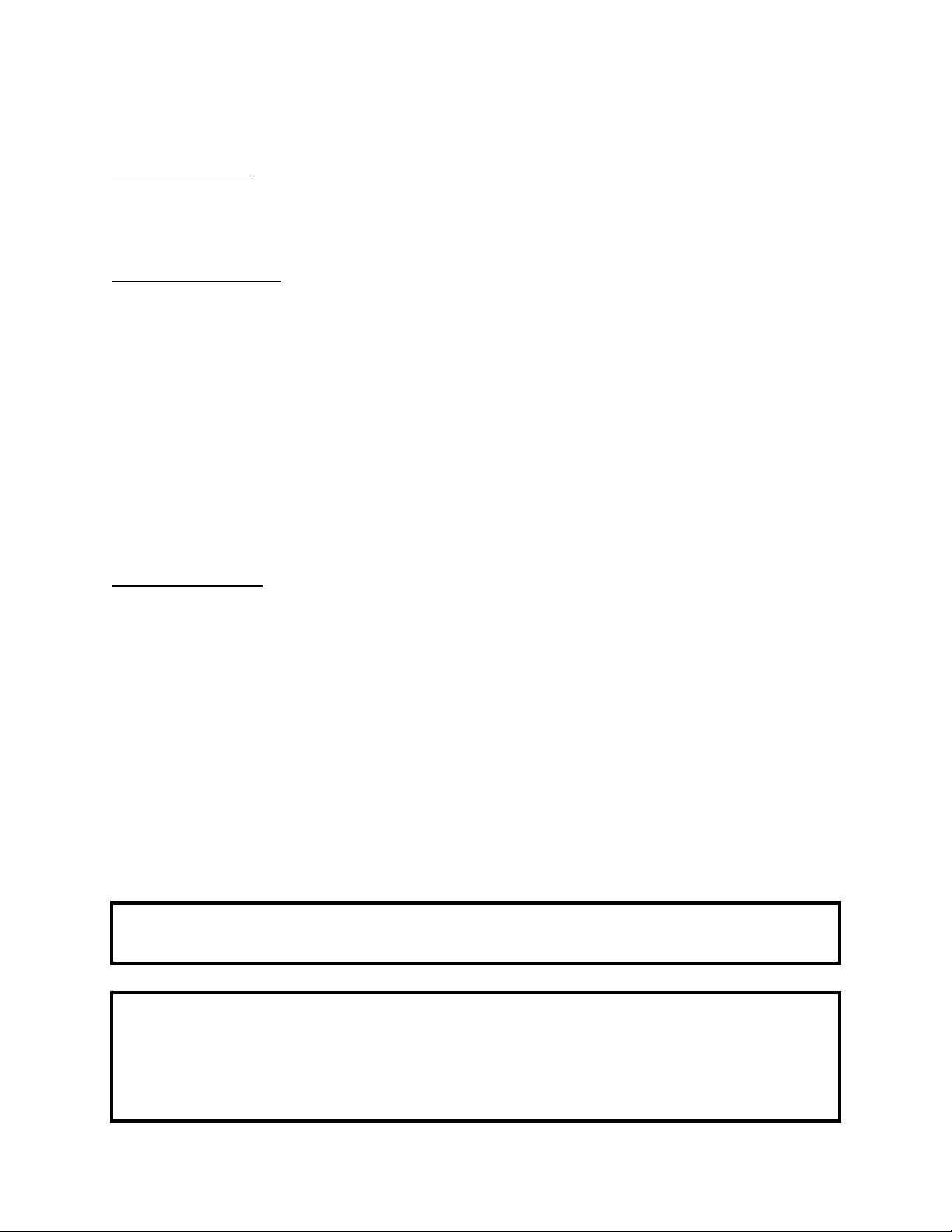
Ceramic fiberboard replacement
Therearefourfiberboards
locatedinthetopofthisstove,in
twolayers.Whilethebottomlayeris
oriented‘North/South’asshown,the
toplayerisoriented‘East/West’.To
replaceacrackedorbrokenboard,
firstremovethefrontburner
tube. Thenremovetheboardyou
needtoreplace. Installthenew
board(theboardsshouldsitflush
togethersidebyside). Replacethe
tubepreviouslyremoved.
Dogboxreplacement
SeeBrickLayout(page33)fordogboxlocationinthefirebox.
Toreplacethedogbox,firstremovetheashpan.Thenremovethetwo9/16”
nutsthatholdthecarriageboltsinplace.Openthefrontdoorofthestoveandliftup
onthedogbox.Installneworexistingcarriageboltsintotheholesontheflangeofthe
dogboxandre‐installinthereversemannerinwhichitwasremoved.
Heatshieldremoval
Therearetwo5/16”screwsthatareontherearoftheheatshield. Toremovetheheat
shield,usinga5/16”socketoropenendedwrench,removethetwoscrews. Thenpulltheheat
shieldupandbackoffthebackpanel.
FiberBoards
(white)
BurnerTubes
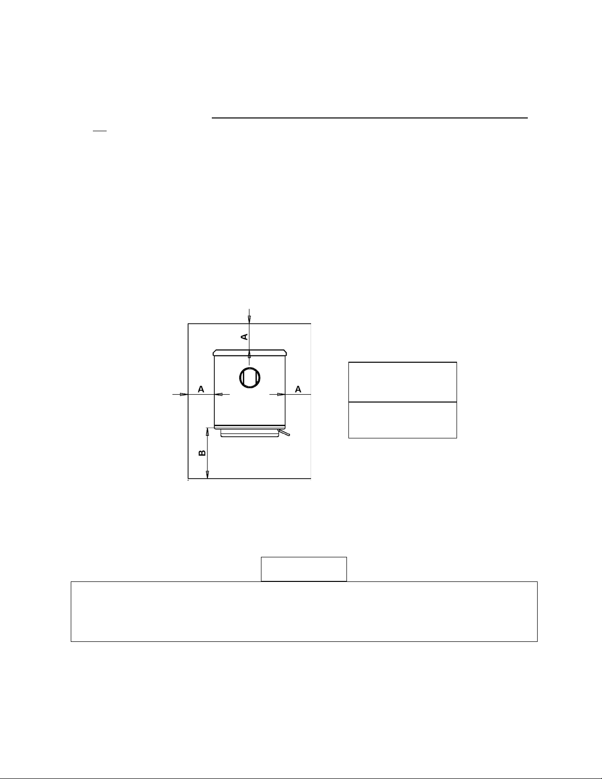
Page | 25
OPTIONALACCESSORIES
Blower:Thewoodstovewasalsodesignedforusewithaconvectionblowerforadditionalheat
circulation. Thestoveisconstructedwithsideconvectionchannelswhichallowtheroomair
blowertopickupheatfromthehottestregionsofthestoveandtransferitintothehome. The
mountingscrewsfortheblowerareinstalledintotherearconvectionchannelatthefactory;
mountingthebloweronlyrequiresa5/16”openendorsocketwrenchtoremovethesescrews
andinstalltheblower.
Operationanduseofelectricalassembliesincludingcareandroutingofpowersupplycord‐
Whenroutingthe powercord,takecaretokeepawayfromhotareasoftheunitandremember
thatthisblowerisforuseonlywiththestove. Pleaseseethediagrambelowforclarificationon
theroomairblowerinstallation.Seepages17and18foroperationinstructions.
ThisunitcanusetheAC‐16(whichcomesstandardwiththeunit) ortheAC‐30upgradeblower.
Bothareinstalledusingthefourfactoryinstalled5/16”screws.
Theoptionalheatcirculationbloweronthisstoverequiresperiodiclubrication;this lubricationshouldbeperformed
nolessthaneverythreemonthsofnormaloperation. Toproperlylubricatetheblower,useaneyedropperor
similardispensingdevicetodrip5‐7dropletsof SAE20oilinto
theoil
portonthesideoftheblowermotor.
AC-16 Blower: 115 V, 60 Hz, .8 Amp
AC-30 Blower: 115 V, 50/60 Hz, 2.1/1.7 Amp
Warning:Disconnectpower
fromfanbeforeinstallation.
(4)5/16”head,self‐tapping
screws(pre‐installedinunit).
Theunitshouldbeunpluggedduringthe
summermonths(andperiodsofnon‐use),to
helpprotectagainstthepossibilityof
damageduetolightningstrikesandother
powerdisruptions.

Page | 26
EPAINFORMATION
Thefollowingadditionstoyourowner’smanualwillenableyoutoachieveoptimal
emissionsperformancefromyoursto ve.Importantsafetytipsarealsoincluded.
‐ ProperInstallation–PleaserefertotheInstallationsectionofyourowner’smanualand
followtheguidelineslistedthereinforsafetyandforoptimalemissionsperformance.
Additionalinformation:
VentingIntroduction:
Draft:Draft isthe forcewhich movesair fromthe applianceupthroughthechimney.The
amount ofdraft in yourchimney depends on the length of the chimney, local geography,
nearbyobstructionsandotherfactors.Too muchdraftmay causeexcessivetemperatures
in the appliance and may damage the catalytic combustor. Inadequate draft may cause
backpuffingintotheroomand‘plugging’ofthechimneyorthecatalyst.
Inadequate draft will cause the appliance to leak smoke into the room through appliance
andchimneyconnectorjoints.
Anuncontrollableburnorexcessivetemperatureindicatesexcessivedraft.
Pleasebemindfulofinstallationlocation:Inversionandotherairqualityissuescanarisein
valleysorifunitisinstalledclosetoneighboringhomes.
Thiswoodstoveoperatesonanaturaldraftsystem,inwhichthechimneysystempulls
airthroughthestove. Thisunitmustbeinstalledinaccordancewiththefollowingdetailed
descriptionsofventingtechniques;notinstallingthestoveinaccordancewiththedetailslisted
herecanresultinpoorstoveperformance,propertydamage,bodilyinjuryordeath. Avoid
make‐shiftcompromiseswheninstallingtheventingsystem. England’sStoveWorksisnot
responsibleforanydamageincurred
duetoapoororunsafeinstallation.
Becertainthatallaspectsoftheventingsystemareinstalledtotheventing
manufacturer’sinstructions,particularlytherequiredclearancestocombustibles. Also,be
certaintouseanatticradiationshieldtopreventinsulationfromcontactingachimneywhich
passesthroughanattic.
Thechimneysystemisthe“engine”whichdrivesawoodstove,soitisimperativefor
properunitfunctionthattheventingsystembeinstalledexactlyasdescribedinthefollowing
section.
Ifquestionsarisepertainingtothesafeinstallationofthestove,ourTechnicalSupport
line(800‐245‐6489)isavailable.Contactyourlocalcodeofficialtobecertainyourinstallation
meetslocalandnationalfirecodes,andifyou’reuncertainabouthowtosafelyinstallthestove,
westronglyrecommendcontactingalocalNFIcertifiedinstallertoperformtheinstallation.
EPACertifiedtocomplywith2020particulateemissionstandardsusingcordwood.

Page | 27
VentingGuidelines:
ALWAYSinstallventpipeinstrictadherencetotheinstructionsandclearancesincludedwith
yourventingsystem.
•
DONOTCONNECTTHISUNITTOACHIMNEYFLUESERVINGANOTHERAPPLIANCE.
•
DONOTinstallafluepipedamper
oranyotherrestrictivedeviceintheexhaustventingsystemofthisunit.
•
USEanapprovedwallthimblewhenpassingthroughawallandaceilingsupport/firestop
whenpassingthroughaceiling.
•
INSTALLthreesheetmetalscrewsateverychimneyconnectorjoint.
•
AVOID excessive horizontal runs and elbows, as both will reduce the draft of the venting
systemandwillresultinpoorstoveperformance.
•
INSPECTyourventingsystemoften,tobecertainitisclearofcreosote,fly‐ashandother
restrictions.
•
CLEANtheventingsystemasdetailedinthemaintenancesectionofthismanual.
•
ADHEREtothe10‐3‐2ruleregardingchimneyterminations.
•
INSTALLsinglewallchimneyconnectorwiththemaleenddowntopreventcreosote
leakage. Followdoublewallchimneyconnectormanufacturer’sinstructionsregardingproper
pipeinstallation.
WARNING:VentingsystemsurfacesgetHOT,andcancauseburnsiftouched. Noncombustible
shieldingorguardsmayberequired
The10‐3‐2Rule:Thechimneysystemmustterminate3.0ftabovethepointwhereit’scenterline
passesthroughtheroofANDthechimneymustterminate2.0ft.abovepartofthedwelling
withina10ft.radiusofthechimney.
‐ OperationandMaintenance–Pleaserefertothe‘Operation’(OperatingInstructions)and
Maintenance(includingAshRemoval/Disposal)sectionsofyourowner’smanualand
followtheguidelineslistedthereinforsafetyandforoptimalemissionsperformance.
AdditionalInformation:
Followingtheinstructionsinyourowner’smanualforBuildingaFirewillensureaproperfire,as
wellashelpingminimizevisibleemissions.
More:
‐ Fuelloadingandre‐loading:PracticalTipsforBuildingaFire–Seeyourowner’smanual
forinformationonloading(andre‐loading)yourfuel,aswellasforfire‐starting
procedures(i.e.‘BuildingaFire’).
‐ Top‐DownFires:TheUSEPArecognizes‘theeffectivenessofthetop‐downapproachfor
startingfires.’Agoodtutorialforthisapproachmaybefoundat
http://woodheat.org/top‐down‐steps.html.Whenbuildingtop‐downfires,besureto
followtheinstructionsfoundinyourowner’smanualandcontactourTechnicalSupport
ifyouhaveanyquestions.

Page | 28
‐ FuelSelection:Onceyourwood‐burningapplianceisproperlyinstalled,buildingan
effectivefirerequiresgoodfirewood(usingtherightwoodintherightamount)andgood
firebuildingpractices.Thefollowingpracticalstepswillhelpyouobtainthebest
efficiencyfromyourwoodstoveorfireplace.
Seasonwoodoutdoorsthroughthesummerforatleast6monthsbeforeburningit.
Properlyseasonedwoodisdarker,hascracksintheendgrain,andsoundshollowwhen
smackedagainstanotherpieceofwood.
Storewoodoutdoors,stackedneatlyoffthegroundwiththetopcovered.
Burnonlydry,well‐seasonedwoodthathasbeensplitproperly.
Startfireswithnewspaperanddrykindlingasdiscussedearlierinthemanual.
Burnhotfires.
Tomaintainproperairflow,regularlyremoveashesfromyourwood‐burningappliance
intoametalcontainerwithacoverandstoreoutdoors.
MoistureMeterInformation
Firewoodisreadyat10‐25%moisturecontent.
Newly‐cutlogscanhaveamoisturecontent(MC)of80%ormore,dependingonspecies.
Sincewoodshrinks,andcanalsosplit,twistorotherwisechangeshapeasitdries,most
woodisdriedbeforebeingused.Airdrying,or‘seasoning,’isthemostcommonmethod
usedforcordwood.InmostpartsoftheUnitedStates,theminimummoisturecontent
thatcanbegenerallyobtainedinairdryingisabout12to15percent.Mostair‐dried
materialisusuallycloserto20percentmoisturecontentwhenused
Totestyourfirewood,simplypushthepinsintothewoodandwaitforareading.
Remember,don'tjuststickthemeterintotheendsofyourfirewood.Togetthemost
accuratereading,splitthewoodandtestthecenter.Thecenterofthelogwillcontain
themostmoisture.
HowFarShouldIDriveNon‐InsulatedPinsintoWood?
Tofulldepthifpossible.However,atmoisturelevelsbelow10%,itisusuallysufficientto
makegood,positivecontactwiththewood.Athigherlevelsofmoistureandespeciallyif
youhaveasteepgradient,fullpenetrationisamust.

Page | 29
‐ WHATFUELSNOTTOUSE:
CAUTION
NEVERUSEGASOLINE,GASOLINE‐TYPELANTERNFUEL,KEROSENE,CHARCOALLIGHTER
FLUID,ORSIMILARLIQUIDSTOSTARTOR“FRESHENUP”AFIREINTHISHEATER.KEEP
ALLSUCHLIQUIDSWELLAWAYFROMTHEHEATERWHILEINUSE.ADDITIONALLY,
NEVERAPPLYFIRE‐STARTERTOANYHOTSURFACEOREMBERSINTHESTOVE.DONOT
USECHEMICALSORFLUIDS
TOSTARTTHEFIRE.
DONOTBURNFLAMMABLEFLUIDSSUCHASGASOLINE,NAPHTHAORENGINEOIL.
DONOTBURNGARBAGE;LAWNCLIPPINGSORYARDWASTE;MATERIALSCONTAINING
RUBBER,INCLUDINGTIRES;MATERIALSCONTAININGPLASTIC;WASTEPETROLEUM
PRODUCTS,PAINTORPAINTTHINNERS,ORASPHALTPRODUCTS;MATERIALS
CONTAININGASBESTOS;CONSTRUCTIONORDEMOLITIONDEBRIS;RAILROADTIESOR
PRESSURE‐TREATEDWOOD;MANUREORANIMALREMAINS;SALTWATERDRIFTWOOD
OROTHERPREVIOUSLYSALTWATERSATURATEDMATERIALS;UNSEASONEDWOOD;
PAPERPRODUCTS,CARDBOARD,PLYWOODORPARTICLEBOARD.THEPROHIBITION
AGAINSTBURNINGTHESEMATERIALSDOESNOTPROHIBITTHEUSEOFFIRESTARTERS
MADEFROMPAPER,CARDBOARD,SAWDUST,WAXANDSIMILARSUBSTANCESFOR
THEPURPOSEOFSTARTINGAFIREINANAFFECTEDWOODHEATER.BURNINGTHESE
MATERIALSMAYRESULTINRELEASEOFTOXICFUMESORRENDERTHEHEATER
INEFFECTIVEANDCAUSESMOKE.
‐ SafeWood‐burningPractices
Onceyourwood‐burningapplianceisproperlyinstalled,followtheseguidelinesforsafe
operation:
Keepallflammablehouseholditems—drapes,furniture,newspapers,andbooks—far
awayfromtheappliance.
Startfiresonlywithnewspaper,drykindlingandallnaturalororganicfirestarters.Never
startafirewithgasoline,kerosene,orcharcoalstarter.
Donotburnwetorgreen(unseasoned)logs.
Donotuselogsmadefromwaxandsawdustinyourwoodstove–theyaremadefor
openhearthfireplaces.Ifyouusemanufacturedlogs,choosethosemadefrom100
percentcompressedsawdust.
Buildhotfires.Formostappliances,asmolderingfireisnotasafeorefficientfire.
Keepthedoorsofyourwood‐burningapplianceclosedunlessloadingorstokingthelive
fire.Harmfulchemicals,likecarbonmonoxide,canbereleasedintoyourhome.
Regularlyremoveashesfromyourwood‐burningapplianceintoametalcontainerwitha
cover.Storethecontainerofashesoutdoorsonacementorbrickslab(notonawood
deckornearwood).Seeashremovalinstructionsinyourowner’smanual.
Keepafireextinguisherhandy.
Remembertocheckyourlocalairqualityforecastbeforeyouburn.

Page | 30
‐ AirControls:SEEYOUROWNER’SMANUALforinformationontheProperUseofAir
Controls(intheOperationsection).
‐ ASHREMOVAL–FollowyourOwner’smanual’sinstructionsregardingremovaland
disposalofashes.
‐ REPLACEMENTofpartsthatarecriticaltoemissionsperformance–FollowyourOwner’s
manual’sinstructionsregardingreplacementofgasketsandotherpartsthatarecriticalto
emissionsperformance.
Remember:“This
woodheaterneedsperiodicinspectionandrepairforproperoperation.Itis
againstfederalregulationstooperatethiswoodheaterinamannerinconsistentwithoperating
instructionsinthismanual.”
More:BurnerTubes–Toreplaceatube,firstbesurethatyouorderthecorrecttubeyouneedto
replace. Thenusinga5/16”socketoropenendwrench,removethescrewlocatedontheleft
sideofthetube. Be suretokeepthescrew.
Pushthetube totherightthenremovethe tube
(pullingthetubebacktotheleftafterthatside
hasbeenremovedfromthehole). Toreplace,
reversetheaboveprocedure…makesuretoinstallthetubesinthecorrectorder.(FronttoBack)
‐ SmokeDetectors
England’sStoveWorks,Inc.highlyrecommendstheuseofsmokedetectorsineveryroomofthe
house.However,locatingasmokedetectordirectlyabovethisunitcanresultinnuisance
alarms.
CAUTION
Thisunitismeanttooperateonlywithdoorclosed.Smokespillageandaninefficient,lazy
burnwillresultfromattemptingtooperatethestovewiththedooropen.
Additionally,usingprohibitedfuelscancreateanunsafesituationandcanalsogenerateexcess
carbonmonoxide.Carbonmonoxideisanodorless,colorlessgaswhichcanbedeadly.
Theuseofacarbonmonoxidedetectorisstronglyrecommended.
Compliance:EPACertifiedtocomplywith2020particulateemissionstandardsusingcordwood.
‐ TamperWarning:“Thiswoodheaterhasamanufacturer‐setminimumlowburnratethat
mustnotbealtered.Itisagainstfederalregulationstoalterthissettingorotherwise
operatethiswoodheaterinamannerinconsistentwithoperatinginstructionsinthis
manual.”
‐ Warranty:SeeyourOwner’smanualforaWarrantyRegistrationinstructionpage,aswell
asinstructionsforwarrantyprocedures.Forparts,warrantyreplacementproceduresmay
befoundatourpartsstoresite:www.heatredefined.com

Page | 31
TROUBLESHOOTING
Issue Cause Solution(s)
Stovesmokesintoroom 1.WeakDraft 1.1Becertainchimneyissufficientlytallto
meetthe10‐3‐2rule.
1.2Addadditionalheighttothechimney.
2.NegativePressurein
theHome
2.1Addanoutsidecombustionairhookupto
theunit.
Fireishardto
start 3.WeakDraft 3.1Becertainchimneyissufficientlytallto
meet10‐3‐2rule.
3.2Addadditionalheighttothechimney
system.
4.ColdChimney 4.1Heatthefluefirstbyburningcrumbled
newspaperinthestove.
4.2Installaninsulatedchasearoundexternal
chimneys.
5.Downdraftin
Chimney
5.1Becertainchimneyissufficientlytallto
meet10‐3‐2rule.
5.2Tryheatingthefluewithahair‐dryerto
correctthedraft.
Glassisdirty 6.WetorGreenWood 6.1Onlyburnwoodthatisseasonedforat
leastoneyearandthatis
dryandfreeofice
andsnow.
7.OperatingStoveat
LowBurnRate
8.WoodLoadedToo
ClosetoGlass
Coalsbuildupinfirebox 9.OperatingStoveat
HighBurnRates
7.1Operatethestoveathigherburnratesto
allowtheair‐washsystemtokeeptheglass
clean.
8.1Neverloadwoodsothatitistouchingthe
ceramicglassviewing
window.
9.1Reducecombustionaircontrolandallow
coalstoburndownbeforereloading.
Fireburnsoutofcontrol 10.ExcessiveDraft 10.1Reducechimneyheight.
11.AirLeakage 11.1Inspectwindowanddoorgasketsand
replaceifnecessary.
12.BurningExcessively
DryWood
Excessivesmokefromstack 13.OperatingStoveat
LowBurnRate
14.WetorGreen
Wood
15.NotCharringFresh
WoodLoad
12.1Onlyburnseasonedcordwood.Donot
burnkilndriedwoodorpalletwood.
13.1Operatethestoveatahigherburnrate
whichwillcreatesecondarycombustion.
14.1Onlyburnwoodthatisseasonedforat
leastoneyearandthatisdry
andfreeofice
andsnow.
15.1Charthefreshwoodloaduntilitis
completelyignitedandactivesecondary
combustionispresentinthefirebox.

Page | 32
REPLACEMENT PARTS LIST
Description
PartNo.
Per
Unit
Rearheatshield(BOLTON) AC‐W02HS
1
Rearpanel(BOLTON) AC‐W02RP
1
Ash
drawer
AC‐ADW01
1
Door
CA‐W02
1
Sideheatshields
AC‐W01SHS 2
LargeUpgradeBlower(optional)
AC‐30
1
Smallstandardblower
AC‐16
1
Glassgasketkit3/4"flat AC‐GGK
1
Doorgasketkit3/4"highdensity AC‐DGKHD
1
Frontburnertube AC‐W06FBT
1
Middleburnertube AC‐W02MBT
1
Rearburnertube AC‐W02RBT
1
Glasssize20.75” X12.625” AC‐G51
1
Ceramicfiberboard AC‐W02CFB 4
Smallspringhandle,Nickel AC‐SH4N
1
Largespringhandle,Nickel AC‐SHN
1
Blowerbackcover AC‐BBC30
1
Glass
tabs
AC‐W01GT
4
Hinge
pins
AC‐HP
2
OutsideAirKit
AC‐OAK3 1
AirDogBox
AC‐DB02 1
*FOR BRICK LAYOUT AND PART NUMBERS PLEASE
SEE PAGE 33*
Page | 33
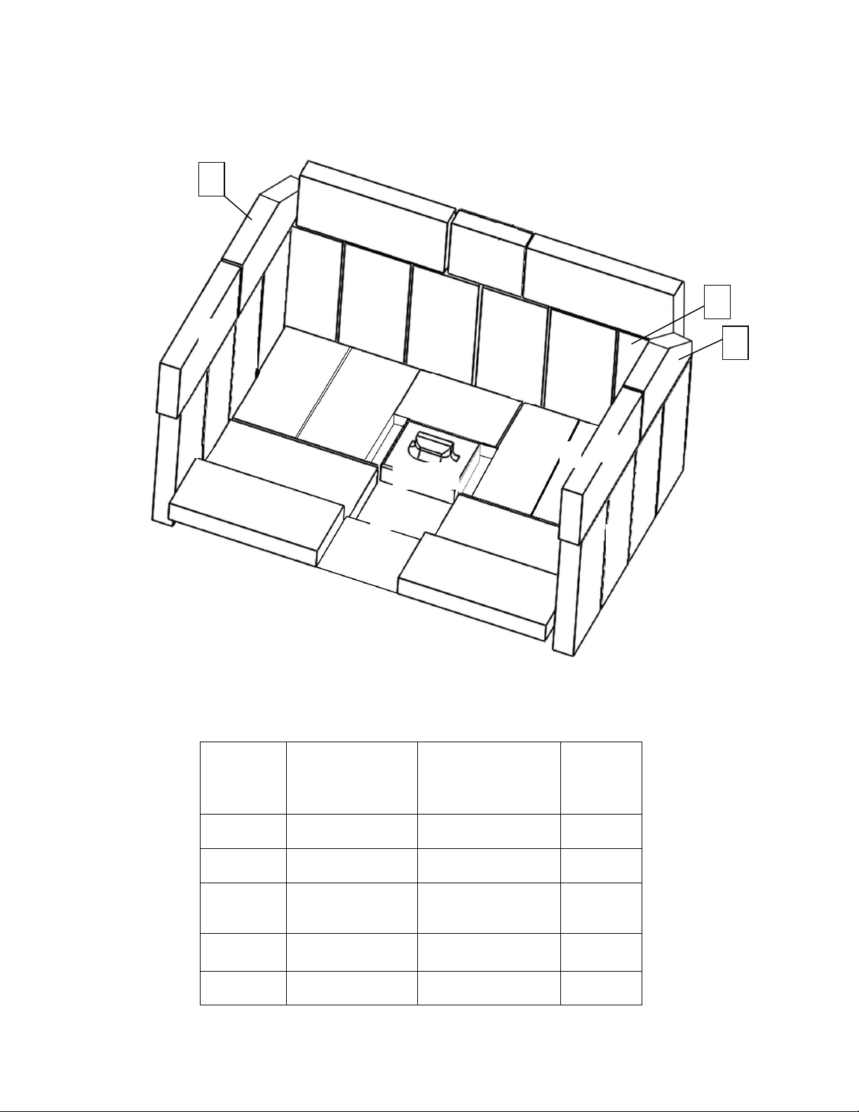
BRICK LAYOUT AND REPLACEMENT
\
NOTE:Thebricksonthesidesandrearwillneedtobeinstalledafterdelivery
DIAGRAM
NUMBER
BRICKSIZE
PARTNUMBER
QUANTITY
PER
STOVE
1 9"X4"X1.25"
AC‐SB
26
2
4.25”X4”X1.25”
AC‐SB4.25
1
3 8”X4”X1.25”
withNotch
AC‐SB8x4
2
4 6.5”X4”X1.25” AC‐SB6.5
1
ASHDUMPPLUG
CA‐30ADP
1
1
2
3
4
3
DogBox
Steel
1
1
1
1
1
1 1
1
1
1
1
1
1
1
1
1
1
1
1
1
1
1
1
1
1
AshPlug
Page | 34
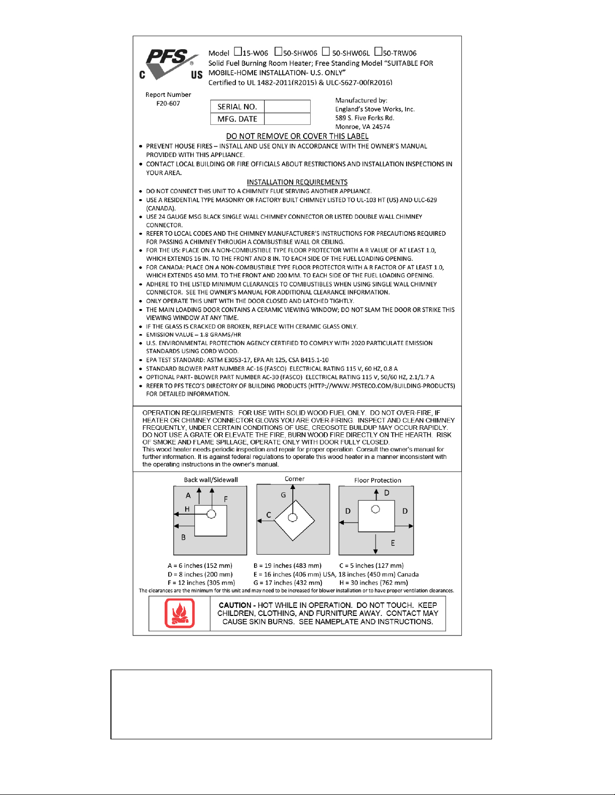
You may write your unit’s Manufacture Date and Serial Number in the blank
spaces on this sample tag, for future reference. This sample tag also
shows
the
safety info. such as UL (ULC) testing standard, etc. for your local
officials, or anyone else who may need reference information.

LIMITED FIVE (5) YEAR
WARRANTY
Fromthedateofpurchasetotheoriginal
owner
Themanufacturerextendsthefollowingwarranties:
Five Year Period:
1. Carbonsteelandweldedseamsinthefireboxarecoveredfo rfive(5)
yearsagainstsplitting.
2. Thecastirondoorandhingesarecoveredforfive(5)yearsagainst
cracking.
One Year Period:
1. Electricalcomponents,accessoryitems,glassandthepaintedsurface
ofthestovearecoveredforone(1)yearfromthedateofpurchase.
Conditions and Exclusions
1. Damageresultingfromover‐firingwillvoidyourwarranty.
2. Thiswarrantydoesnotapplyifdamageoccurs becauseofan
accident,improperhandling,improperinstallation,improperoperation,
abuseorunauthorizedrepairmadeorattemptedtobemade.
3. Themanufacturerisnotliableforindirect,incidental,or
consequential damages
inconnectionwiththeproductincludinganycost
orexpense,orserviceduringperiodsofmalfunctionornon‐use.*DoNOT
usesubstitutematerialsorcomponentstoreplaceoriginalequipment.
4. Allliabilityforanyconsequentialdamageforbreachofanywrittenor
impliedwarrantyisdisclaimedandexcluded.
5.
Thiswarrantydoesnotcoverinternalwearpartsofthecombustion
system,including thefirebrickliningandgaskets.
6. Warrantyisvoidifunitisnotusedaccordingtotheowner’sm a nual.
**Somestatesdonotallowtheexclusionoflimitationsofincidentalorconsequentialdamages,sotheabovemaynotapplyto
you.**
Procedure
Purchasermustgivenoticeofclaimofdefectwithinthewarrantyperiod
andpaytransportationtoandfroma servicecenterdesignatedbythe
manufacturer. Thedealerfromwhichtheunitwaspurchasedorthefactory,
atouroption,willperformthewarrantyservice.
Other Rights
Thiswarrantygivesyouspecificlegalrights;youmayalsohaveotherrights,
whichmayvaryfromstatetostate.
Forparts,warrantyreplacementproceduresmaybefoundatourpartsstoresite:
heatredefined.com

Page |36
Important Notice
This registration information MUST be on file for this warranty to be valid. Please
mail this information, along with a copy of the sales receipt, within thirty (30) days from
the original date of purchase.
Use any of these three easy ways to send your warranty information in!
Mailing
Address
England’s Stove Works,
Inc.
Technical Support
Department
P.O. Box
206
Monroe, Virginia
24574
Fax
Number
(434) 929-4810 – Twenty-four hours a
day.
Online
Registration
Visit our warranty registration website
at:
www.heatredefined.com
(WARRANTY CARD LOCATED ON NEXT PAGE)
For parts, warranty replacement procedures may be found at
our parts store site: www.heatredefined.com

WARRANTY REGISTRATION for England’s Stove Works®
Purchaser Information
I.
Purchased
By
(Name)
II.
Address
III.
City
State
Zip
Code
IV.
Telephone
Number
V.
Email
Address
Dealer Information
VI.
Purchased
From
VII.
Address
VIII.
City
State
Zip
Code
Unit Information
*Refer to the sticker on the back of the manual or box to complete this section.
IX.
Model
Number
Purchase
Date
X.
Purchase
Price
XI.
Serial
Number
Mfg.
Date
Purchase Questions
How did you first hear about our product? (Please check one)
Word
of
Mouth
Burn
Trailer
Demonstration
Internet
Other:
Where did you receive information about our product?
Via
Telephone
Dealer
(Name
of
dealer)
Internet
Other:

15‐W06,50‐SHW06,50‐SHW06L,50‐TRW06
GUIDED’INSTALLATIONETD’UTILISATION
MISEENGARDE
Veuillezlirel’intégralitéduprésentguideavantd’installeretd’utilisercetappareil
dechauffageaubois.Gardeztoutappareildechauffagehorsdeportéedesenfants,
etàbonnedistancedesmeublesetdesmatièrescombustibles.
CONSERVEZCESINSTRUCTIONS
AVISDESÉCURITÉ
Lenon‐respectdecesinstructionspeutcauserdesdommagesmatériels,desblessuresou
mêmelamort.Pourvotresécuritéetvotreprotection,suivezlesinstructionspour
l’installationdécritesdansceguide.Communiquezaveclesautoritéslocalesenmatière
deconstructionouleserviced’incendieafindeconnaîtrelesrestrictionsetlesexigences
d’inspectiondesinstallations(ycomprisl’obtentiondepermis)devotrerégion.
Rév.10/2020
PFSnumérode
dossier:20‐607
AFIND’ASSURERLEBONFONCTIONNEMENTDUPOÊLEÀBOIS,VOUSDEVEZL’INSPECTER
ETLERÉPARERPÉRIODIQUEMENT.CONSULTEZLEGUIDED’UTILISATIONPOUROBTENIR
DEPLUSAMPLESRENSEIGNEMENTS.ENVERTUDESRÈGLEMENTSFÉDÉRAUX,ILEST
INTERDITD’UTILISERCEPOÊLEÀBOISD’UNEMANIÈRENONCONFORMEAUMODE
D’EMPLOIINDIQUÉDANSLEGUIDED’UTILISATION.
Fabriquépar:England’sStoveWorks,Inc.POBox206Monroe,VA24574,États‐Unis
Questions?Besoindepiècesou
d'options?www.heatredefined.com
PourunserviceenFrançais–
Courriel:
[email protected]
Telephone(844)411‐2654
Page | 2
IMPORTANT:ENCASDEPROBLÈMEAVECCETAPPAREIL,NE
LERETOURNEZPASAUDÉTAILLANT.COMMUNIQUEZAVEC
LESERVICEDESOUTIENTECHNIQUEAU1800245‐6489.
Utilisationdansunemaison(approuvéepourlesÉtats‐Unis
seulement):
Cetappareildechauffageauboisautop ortantestapprouvé
pourune
utilisationdansunemaisonmobileoupourune
installationendoublelargeuravecleraccordementd’air
comburantextérieur.Consultezlasection «Installation »du
présentguidepourconnaîtrelesdétailsrelatifs àl’installation
dansunemaisonmobile.L’installationdansunemaisonmobile
doitêtreconformeàlanormeManufacturedHome
andSafety
Standard(HUD),CFR3280,partie24,desÉtats‐Unis
Conservezdansvosdossiers
Numérodemodèle
Dated’achat
Datedefabrication
Numérodesérie
*Cesrenseignementssontinscritssurl’étiquettedesécuritéfixéeàl’arrièrede
l’appareil.Ayezcesrenseignementsàportéedelamainsivousappelezlefabricant
ouvotredétaillantausujetdeceproduit.
• Gardezlesenfantsàl’écart.
• Surveillezlesenfantsquisetrouventdanslamêmepiècequecetappareil.
• Prévenezlesenfantsetlesadultesdesrisquesquereprésententles
températuresélevées.
• N’utilisezPASl’appareilsilesbarrièresdeprotectionsontouvertesouretirées.
• Cetappareilestchaudlorsqu’ilestenmarche!Tenezlesvêtements,
lesmeubles,lesrideauxetlesautresmatièrescombustiblesàbonne
distance.Lecontactavecl’appareilpeutbrûlerlapeau!
• Évitezl’emballementdupoêle.
• L’installationDOITêtreconformeauxcodesetauxrèglementsmunicipaux,
régionaux,provinciauxetnationaux.
• Consultezlesautoritéslocalesenmatièredeconstruction,leservice
d’incendieoulesorganismesdecontrôlelocauxàproposdesrestrictions,
del’inspectiondesinstallationsetdel’obtentiondepermis.
ATTENTION
Page | 3
BIENVENUE!
Introduction
• Remerciements....................................4
Caractéristiques
• Caractéristiquesdechauffage............5
• Dimensions.........................................5
• Conformitéauxnormesdel’EPA........5
Installation
• Vued’ensembledel’installation........6
• Distancesminimalesavecles
matièrescombustibles........................7
• Généralitéssurlaventilation.............8
• Consignespourlaventilation.............8
• Renseignementssupplémentaires
surlaventilation.................................9
• Traverséesdemur............................10
• Méthodesdeventilationapprouvées
oÀtraverslemur.......................11
oÀtraversleplafond.................12
oCheminéeenmaçonnerie.......13
oFoyerenmaçonnerie..............14
• Installationdansunemaison
mobile..............................................15
• Raccordementd’airextérieur...........15
• Protectionduplancher.....................16
Fonctionnement
• Premiersfeux...................................17
• Utilisationcontinuelle.................17‐18
• Avisdesécurité…………………………19‐20
Entretien
• Entretiendupoêle............................ 21
• Inspectiondesjointsd’étanchéité......22
• Fini......................................................22
Remplacementdescomposants
• Vitre....................................................23
• Tubesdebrûleur.................................24
• Panneauenfibresdecéramique........24
• Écranthermique....................................24
• InformationssurleVentilateur...........25
Informationsimportantes
• Renseignementssurl’EPAet
lasécurité...........................................26
Guidededépannage
• Dépannage..........................................31
Illustrationdétailléedespièces
• Listedespièces................................... 32
• Dispositiondesbriques.......................33
Garantie
• Étiquettederéférence........................34
• Détailsdelagarantie..........................35
• Avisimportant....................................36
• Formulaired’enregistrementde
lagarantie...........................................37
REMARQUE:Sivousavezachetécemodèle,enfonctiondesmagasins,lenumérodemodèlepeutseterminer
par«L»,«LC»,«H»,«CT»,etc.Ceguideconcernecesmodèleségalement.
CemanuelpeutêtretéléchargégratuitementsurlesiteWebdufabricant.Ils’agitd’u ndocumentprotégéparun
droitd’auteuretileststrictementinterditdelerevendre.Lefabricantpeutoccasionnellementmettreàjource
manueletnepeutêtretenuresponsabledeproblèmes,ycomprislesblessuresou
lesdommagesrésultantde
l’utilisationderenseignementstrouvésdansunmanuelprovenantdesourcesnonautorisées.
ATTENTION:Lepoêleestlourd.
Deplus,lorsquevousmanipulezdestôles,rappelez‐vousqu’ilpeutyavoirdesbordscoupantsoudesbavures.
Bienquenousfassionstousleseffortspossiblespour
éliminerlesbordscoupants,veuillezfairepreuvede
prudencelorsquevousmanipulezdespiècesdemétal.
N’oubliezpasdedéconnecter(débrancher)lepoêledelasourced’alimentation
etdelelaisserrefroidircom
p
lètementavantd’eneffectuerl’entretien.
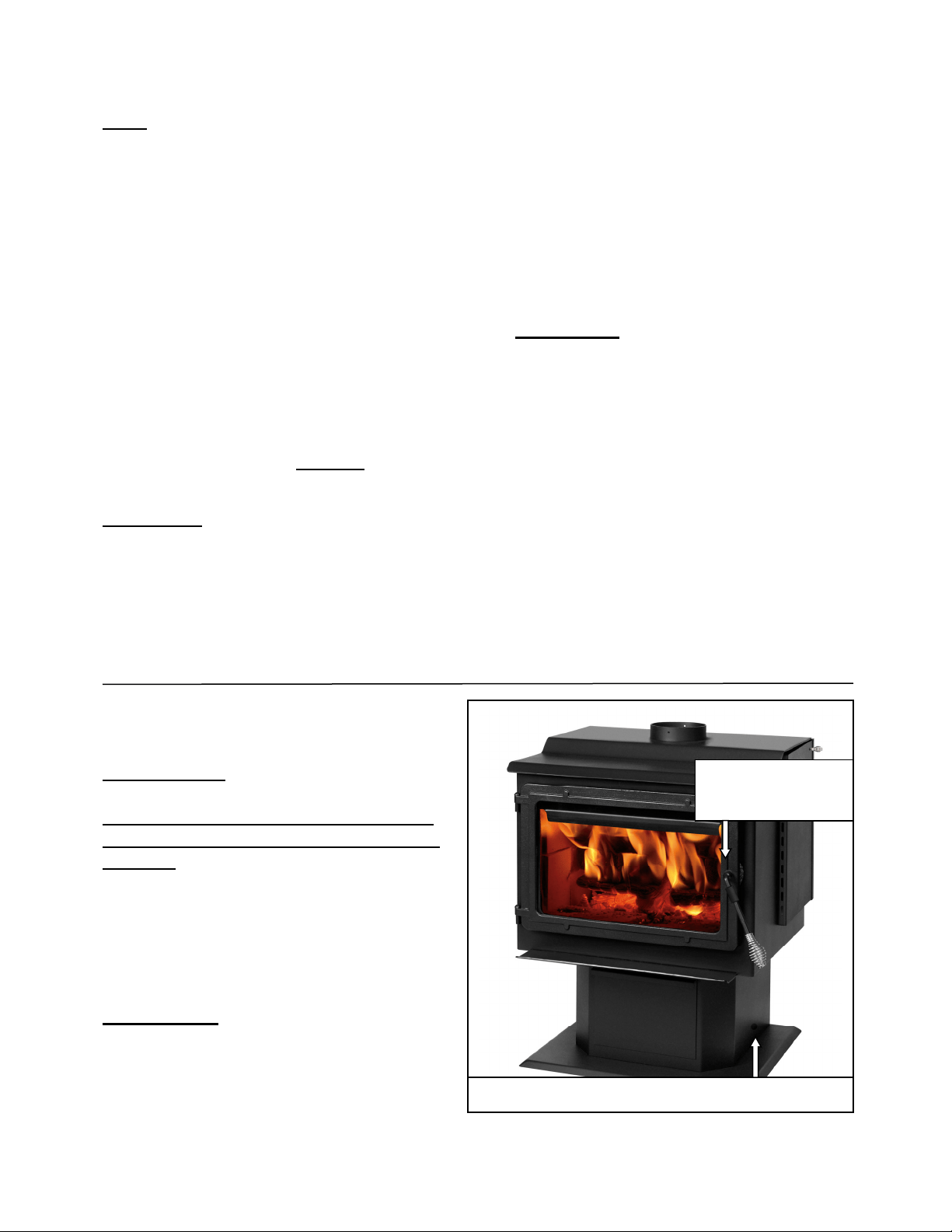
Page | 4
Merci d’avoir acheté cet excellent produit de la gamme England’s Stove Works.
La famille qui a fondé et possède encore England’s Stove Works croit fermement que les
travaux que l’on réalise soi-même sont les plus satisfaisants; voilà pourquoi vous avez
trouvé ce poêle auprès de votre magasin préféré de produits prêts à assembler.
Nous concevons et fabriquons nos poêles expressément pour que n’importe quel
propriétaire soit en mesure de les entretenir avec des outils de base. De plus, nous
sommes toujours disposés à vous montrer comment procéder de la façon la plus simple et
la plus économique qui soit.
En offrant des fiches d’entretien téléchargeables gratuitement et un guide de dépannage
intelligent sur notre site Web, nous tentons d’aider nos clients à être prêts à utiliser leur
appareil de chauffage en tout temps, d’autant plus que le prix du mazout et de l’électricité
ne cesse d’augmenter.
Si vous avez besoin d’aide au sujet de votre appareil, veuillez consulter la vaste section
d’aide de notre site Web ou appeler notre service de soutien technique au 1 800 245-6489.
Nous sommes presque toujours en mesure de vous guider en cas de réparation à effectuer
ou de problème, ou encore de répondre à vos questions.
REMARQUE : Les renseignements obtenus sur notre site Web ou en composant notre
numéro sans frais sont gratuits en tout temps. Cependant, les réparations ou l’entretien
que nous offrons sur place occasionnent des frais.
Nous vous souhaitons des années de chauffage agréable, efficace et de qualité.
Service de soutien technique d’England’s Stove Works
www.HeatRedefined.com (800) 245-6489 (EN) (844) 411-2654 (FR)
POIGNÉE DE PORTE AMOVIBLE
Veuillez noter: Cet appareil est livré
avec une poignée de porte amovible,
qui doit être retirée du poêle lorsqu'il
n'est pas utilisé pour ouvrir ou fermer
la porte.
Pour utiliser la poignée, placez-la
simplement sur la tige de la poignée
de porte située sur la porte du poêle.
La poignée peut ensuite être stockée
dans le trou situé sur le côté droit du
piédestal lorsqu'elle n'est pas utilisée.
ATTENTION - La poignée deviendra
CHAUDE si elle est laissée sur le
poêle
.
Tigedepoignée
deporte
Troupourlestockagedelapoignée
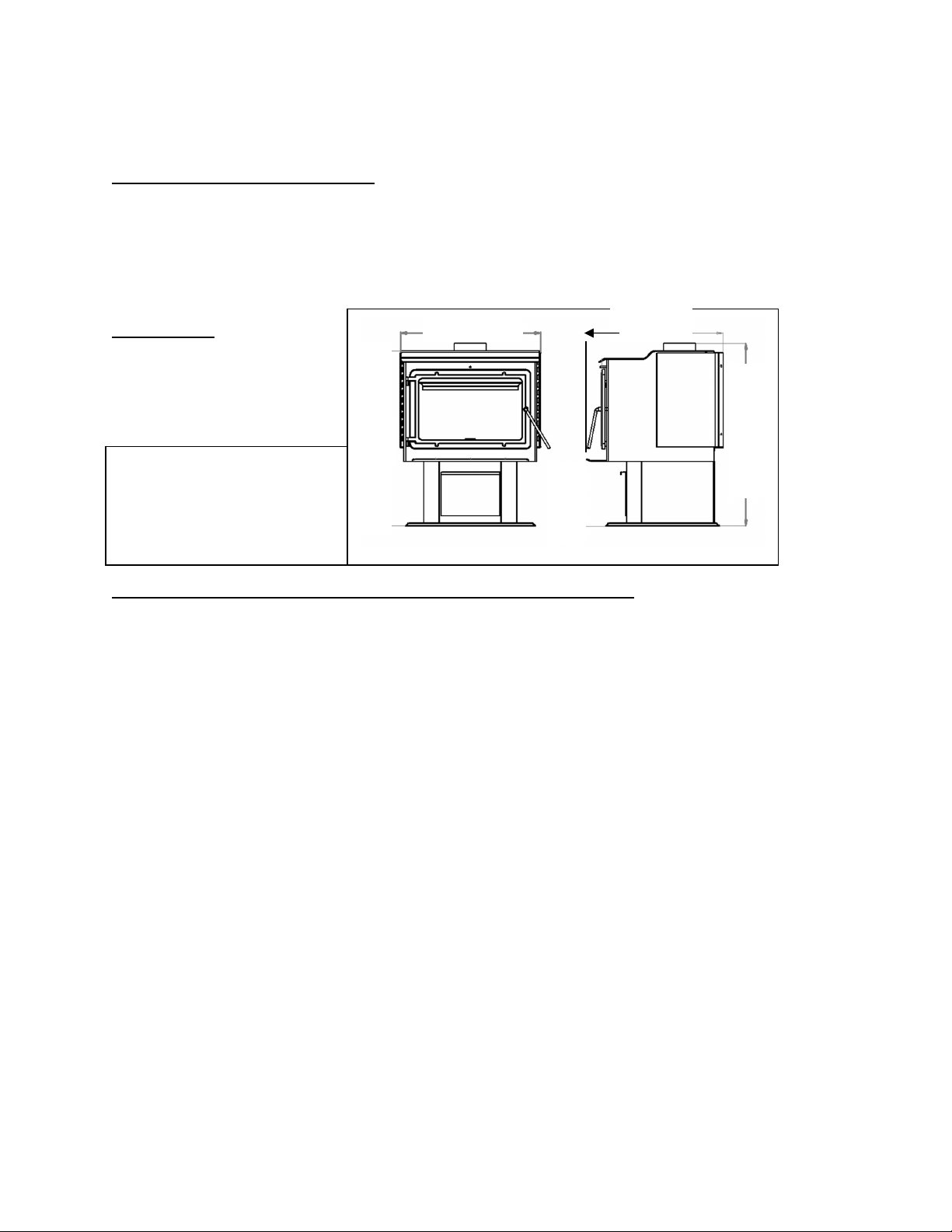
Page | 5
CARACTÉRISTIQUES
Caractéristiquesde chauffage
• Duréemaximaledecombustion**........................................... Jusqu’à14heures
• Superficieapproximativechauffée***..................................... 222,97m²(2400pi²)
• Buse.......................................................................................... 15,24cm(6po),ronde
Dimensions
Conformitéauxnormes de sécurité etauxnormesde l’EPA
StatutdeconformitéEPA…….......Certifiéconformeauxnormesde2020surl’émissionde
particuleslorsdel’utilisationdecordwoodparl’ENVIRONMENTALPROTECTIONAGENCYdes
États‐Unis.
NormedetestpourlesEPA…………………….ASTME3053‐17,EPAAlt125,CSAB415.1‐10
• Émissionsdeparticules………………………………………..…………………………………. 1,8g/h
• Émissionsdemonoxydedecarbon..........................................………………. 1,9g/min
• Gammedeproductiondechaleur………..………..………………….……..17500–65900Btu/hr
• Efficacité*.................................................................................…………….…. 72%PCS
Certifiéà………………………………………………..UL1482‐2011(R2015)andULC‐S627‐00(R2016)
**Laduréemaximaledecombustiondépendfortementdutypedeboisbrûlédanslepoêle;cesvaleurspeuvent
doncvarier.
***Lacapacitémaximaledechauffagedecetappareilpeutvarierconsidérablementselonleclimat,letypede
construction,l’isolationetdenombreuxautresfacteurs.Combinezlesrenseignementsexpo s ésdans
leprésent
guideauxré sultatsd’uncalculdedéperditionthermiquepourvotremaisonafindedéterminersi cetappareil
suffiraàcomblervosbesoins.
AVERTISSEMENTRELATIFAUXMODIFICATIONS:«Cepoêleàboisestdotéd’untaux
decombustionbasminimumrégléenusinequinedoitpasêtremodifié.Envertudes
règlementsfédéraux,ilestinterditdemodifierceréglageetd’utilisercepoêleàbois
d’unemanièrenonconformeaumoded’emploiindiquédansleprésentguide.»
«Afind’assurerlebonfonctionnementdupoêleàbois,vousdevezl’inspecteretleréparer
périodiquement.Envertudesrèglementsfédéraux,ilestinterditd’utilisercepoêleàbois
d’unemanièrenonconformeaumoded’emploiindiquédansleprésentguide.»
34
1
/
4
35
3
/
4
27
3
/
8
23
3
/
4
91cmdehaut
66cmde
profondeur
69cmdelarge
*Lesspécificationssont
approximatives.Assurez‐vousde
localiservotrepoêledanslazone
d'installationavantd'installerle
tuyau,etc.
Page | 6
INSTALLATION
Vued’ensemble del’installation
Lorsquevouschoisissezl’emplacementdevotrenouveaupoêle,vousdeveztenircompte
d’ungrandnombredefacteursavantdecommencerl’installation.
1. Habitudesdepassage–Afindeprévenirlesaccidents,lepoêledoitêtreinstalléàunendroit
oùiln’encombrepaslepassagehabitueldanslamaison.
2. Fluxdechaleuretefficacité–Tenezcomptedelafaçondontlachaleurcirculedansvotre
maisonpourdéciderdel’endroitoùvousinstallerezvotrepoêle.Installezlepoêleàl’endroit
quevousavezbesoindechauffer.Souvent,uneinstallationensous‐solnepermetpas
qu’unechaleursuffisante
atteignelesétagessupérieurs,alorsqu’uneinstallationaudernier
étagenepermetpasquelachaleurserendeauxétagesinférieurs.N’oubliezpasque,tant
qu’ilestchaud,l’airmonteetempruntelecheminoffrantlemoinsderésistance.
3. Emplacementdel’évacuation–Lemoteurd’unpoêle àbois estlesystèmedecheminée;
ilestdoncimportantd’examineravecprécisionlaméthoded’intégrationdusystèmede
cheminéelorsdel’installationdupoêle.Idéalement,lacheminéed’unpoêleàboisdevrait
êtreenpositioncomplètementverticaleàpartirde
labusedel’appareiljusqu’àl’extrémité
seterminantau‐dessusdelalignedetoiture.Unsystèmedecheminéesituécomplètement
àl’intérieurdel’enveloppechaufféedelamaisonassurerauntiragefortetfacileàamorcer
danslacheminée.Bienquelessystèmesdecheminéeextérieursfonctionnentsouventde
façonadéquate,ilssubissentplussouventlecontre‐tiraged’airfroidàl’allumageousont
fréquemmentlacaused’untiragefaibledel’appareil.Tenezcompteégalementdelasection
transversaledelacheminée.Mêmesilescheminéesenmaçonnerieexistantespeuvent
souventêtreutilisées,ilseradifficile,voireimpossible,defaire
fonctionnercorrectement
l’appareilavecunegrandecheminéeenmaçonnerieextérieure.Dansuntelcas,ilsera
souventnécessaired’utiliserunedoubluredecheminéeisolanteafindefournirletirage
nécessaire.
4. Constructiondumur–Lefaitdedisposerlepoêledesortequelesystèmed’évacuation
passeentrelesmontantsd’unecloisonsimplifiel’installationetéliminelanécessitéde
restructurerlessectionsdemuroudeplafondpouryposerlemanchond’emboîtement
muraloulaboîted’encastrementdeplafond.
AVERTISSEMENT
• Nestockezpasetn’utilisezpasd’essencenitouteautrevapeurouliquide
inflammableàproximitédecetappareiloudetoutautreappareil.
• Évitezdesurchaufferlepoêle.Sidespiècesextérieurescommencentà
rougeoyer,ilyasurchauffe.Réduisezl’alimentationenair.Lasurchauffe
annuleravotregarantie.
• Respectezlesindicationsrelativesauxdistancesminimalesaveclesmatières
combustibles.Lenon‐respectdecesexigencespourraitprovoquerl’incendie
delamaison.
• Testéetapprouvépourduboisenstéréseulement.L’utilisationdetout
autrecombustibleannuleravotregarantie.
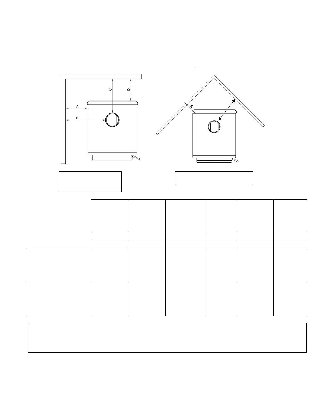
Page | 7
INSTALLATION
Distancesminimales avecles matièrescombustibles
Installationparallèle
aumur
Installationencoin
Del’appareil
aumur
latéral
Duraccordde
cheminéeau
murlatéral
Duraccordde
cheminéeau
murarrière
Del’appareil
aumur
arrière
Del’appareil
aucoin
Duraccord
decheminée
aucoin
A
B
C
D
E
F
mm(po)
mm(po)
mm(po)
mm(po)
mm(po)
mm(po)
Raccorddecheminée
àparoisimplesurune
surfacenonprotégée
avecécranslatéraux
483
(19)
762
(30)
305
(12)
152
(6)
127
(5)
432
(17)
Raccorddecheminéeà
paroidoublesurune
surfacenonprotégée
avecécranslatéraux
483
(19)
762
(30)
305
(12)
152
(6)
127
(5)
432
(17)
Notespourcetteuni té:Leproduitpeutdifférerlégèrementdesdiagrammes.Lesdégagementssontleminimum
pourcetteunitéetpeuventdevoirêtreaugmentéspourl'installationduventilateurouavoirdesdé gagementsde
ventilationappropriés.Respecteztouslesdégagementsdufabricantdeventilationetlescodeslocaux.
F
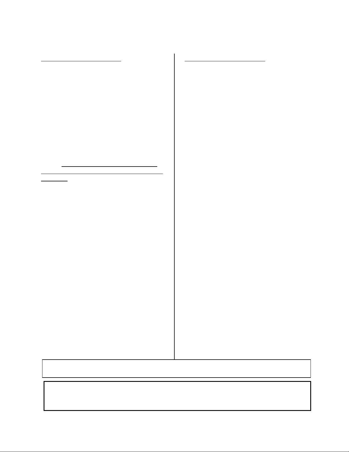
Page | 8
Généralités surlaventilation
INSTALLATION
Consignespourla ventilation
Cepoêleàboisutiliseunsystèmede
tiragenatureldanslequellesystème de
cheminéetirel’airdan slepoêle.Cetappareil
doitêtreinstalléconformémentauxtechniques
deventilationdécritesendétailci‐apr ès.Lenon‐
respectdesdétailsmentionnéspourraitréduire
sonrendemen t etcauserdesdommages
matériels,
desblessu resoulamort.Évitez
d’avoirrecoursàdesexpédientslorsde
l’installationdusystèmedeventilation.
England’sSt ove Worksn’estpasresp onsabledes
dommagescausésparuneinstallati onincorrecte
ounonsécuritaire.
Assurez‐vousdebiensui vretoutesles
instructionsdufabricantrelativesausy stèmede
ventilation,surtoutparrapportauxdistances
minimalesnécessairesaveclesmatières
combustibles.Assurez‐vouségalementd’utiliser
unécrananti ray o nn ementdegrenierafin
d’éviterquel’isolantentreencontactavecune
cheminéequitraverseungrenier.
Lesystèmede cheminéeestle
«moteur»dupoêleàbois.Ilestdoncessentiel
quelesy s t èmedeventilation
soitinstallé
exactementselon ladescriptionindiquéedans
lasectionsuivant e afind’assurerun
fonctionnementadéqua tdel’appareil.
Pourtoutequestionrelativeà
l’installationsécuritairedupoêle,appe lez
notreserv ice desoutientechniqueau1800245‐
6489.Communiquezavecunagent responsable
localafindevou s assurerquel’installation
est
conformeauxexigences municipaleset
nationalesenmatièredepréventiondes
incendies.Sivousn’êtespascertaindepouvoir
installerlepoêledefaçonsé cu ri ta i re ,nousvous
suggéronsfortementdefaireappelàun
installateurlocalcertifiéparleNFI(Nat ional
FireplaceInstitutedesÉtats‐Unis).
• InstallezTOUJOURS
letuyaude
ventilationenrespectant rigoureusement
lesinstruct i ons etlesindicationssurles
dégagementsquiacc omp ag nentle
systèmedeventilation.
• NERACCORDEZPASLEPOÊLEÀBOISÀ
UNCON DUITDEFUMÉEDÉJÀUTILIS É
POURUNAUTREAPPAREIL.
• N’installezPASdere gi str edetirage,
niaucunautredispositif
deréglagedans
lesystèmed’évacuationparventilation
decetappareil.
• UTILISEZunmanchond’emboîtement
muralhomologuépourtraverserunmur
etunsupp o rtdeplafondouuncoupe‐feu
pourtraverserunplafond.
• INSTALLEZtroisvisàtôlesur chaquejoint
deraccorddecheminée.
• ÉVITEZ
detropnombreuxcoudeset
parcourshorizontaux,carilsrédu ir ontle
tiragedusystèmedeventilation,cequi
nuiraaurendementdupoêle.
• INSPECTEZsouventlesy s tèmede
ventilationafindevousassurerqu’ilne
contientpasdecréosote,decendres
volantesoud’autresobstruct ions.
• NETTOYEZlesystèmede
ventilati on
commeilestdécritdanslasectionsur
l’entretien duprésentguide.
• RESPECTEZlarègle10‐3‐2concernantles
raccordementsdelachemin ée.
• INSTALLEZleraccorddecheminéeàparoi
simpleavecl’extrém itémâleverslebas
pouréviterlesfu it esdecréosote.Suivez
lesinstruct i ons
dufabricantderaccords
decheminéeàparoidoublec onc ernant
l’installationadéquatedestuyaux.
AVERTISSEMENT:LessurfacesdusystèmedeventilationdeviennentCHAUDES
etpeuventcauserdesbrûluressivouslestouchez.Ilpeutêtrenécessaired’utiliser
unrevêtementoudesgrillesdeprotectionincombustibles.
Le passage au travers d’un mur ou d’une cloison en matériau de construction combustible
doit être réalisé conformément à la norme CAN/CSA-B365.
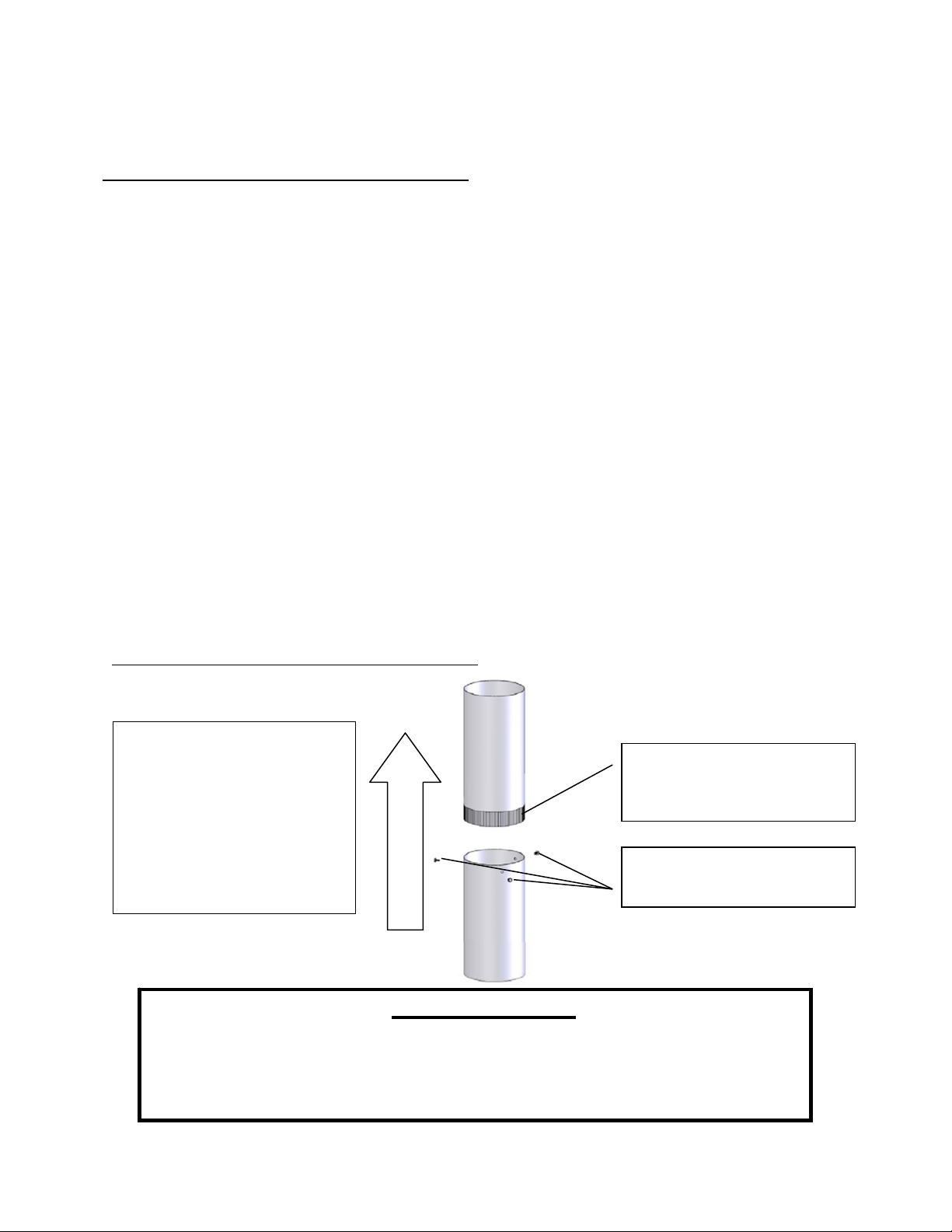
Page | 9
Directiondesgaz
decombustion
INSTALLATION
Renseignements
supplémentaires surlaventilation
• Nemélangezpasetn’appariezpasdecomposantsprovenantdedifférentsfabricantsdetuyaux
lorsquevousinstallezlesystèmedeventilation(parexempl e,n’utilisezPASuntuyaudeventilation
d’unfabricantetunmanchond’emboîtementd’unautrefabricant).
• Nousexigeonsunehauteurmini male decheminéede4,57m(15pi).Dessystèmesdecheminée
pluscourtspourraientnepasassurerletiragenécessaireaufonctionnementad équatdecepoêle
àbois.
• N’ayezpasrecoursàdesexpédientslors del’installa tiondusystèmedeventilation.Faites
inspecterlesystèmedecheminéeexistantavantdel’utiliseretassurez‐vousquetoutnouveau
systèmedecheminéeestinstalléselonlesspécificationsdufabricantetseulementavecles
composantshomologuésUL(ULCauCanada).
• Lessystèmesdeventilationpréfabriqué sutiliséspourcepoêledoiventêtrehomologuésULCS629
(Canada)etUL103HT(États‐Unis).
• N’installezjamaisdesystèmedetirageparaspirationnitoutautresystèmequiaugmentele
tiragenatureldelacheminée.Deplus,n’installezpasderegistreba rométriquenideregistrede
tiragesurcetappareil.
• N’utilisezjamaisderaccorddecheminéeàparoisimpleoudoublecommesystèmedecheminée.
Nefaitesjamaispasserunraccorddecheminéedans unmurcombustiblesansrespecteràla
lettrelesinstructionsdufabricantetcellesindiquéesàlapagesuivanteconcernantlestraversées
demur.Nefaites
JAMAISpasserunraccorddecheminéeàtraversungrenier,unplancher,un
placardouuntoit.
• Utilisezuniquementunraccorddecheminéenoiràparoisimpledecalibre24MSGouunraccord
decheminéeàparoidoublehomologué UL(ULCauCanada).
Installation d’unraccord decheminée àparoi simple
L’extrémitémâleduraccordde
cheminéeàparoisimpledoit
êtreorientéeverslebaspour
quelacréosoteliquidedans la
busepuisses’écoulerdans
l’appareilplutôtqu’àl’extérieur
dutuyau(letiragenatureldans
lesystèmedecheminée
empêcheralafuitedefumée
parlesjoints).
L’extrémitésertieoumâledu
raccorddecheminéeàparoi
simpledoitêtreorientéevers
lebas.
Fixezchaquejointderaccord
decheminéeàparoisimpleà
l’aidedetroisvisàtôle.
AVERTISSEMENT
• INSTALLEZL’ÉVEN TENRESPECTANTLESDÉGAGEMENTSINDIQUÉSPARLEFABRICANT
DEL’ÉVENT.
• CHAUD!N’ytouchezpas!Celapourraitentraînerdegravesbrûluresoul’inflammation
desvêtements.
• Lavitreetlesautressurfacessontchaudesdurantlefonctionnement.
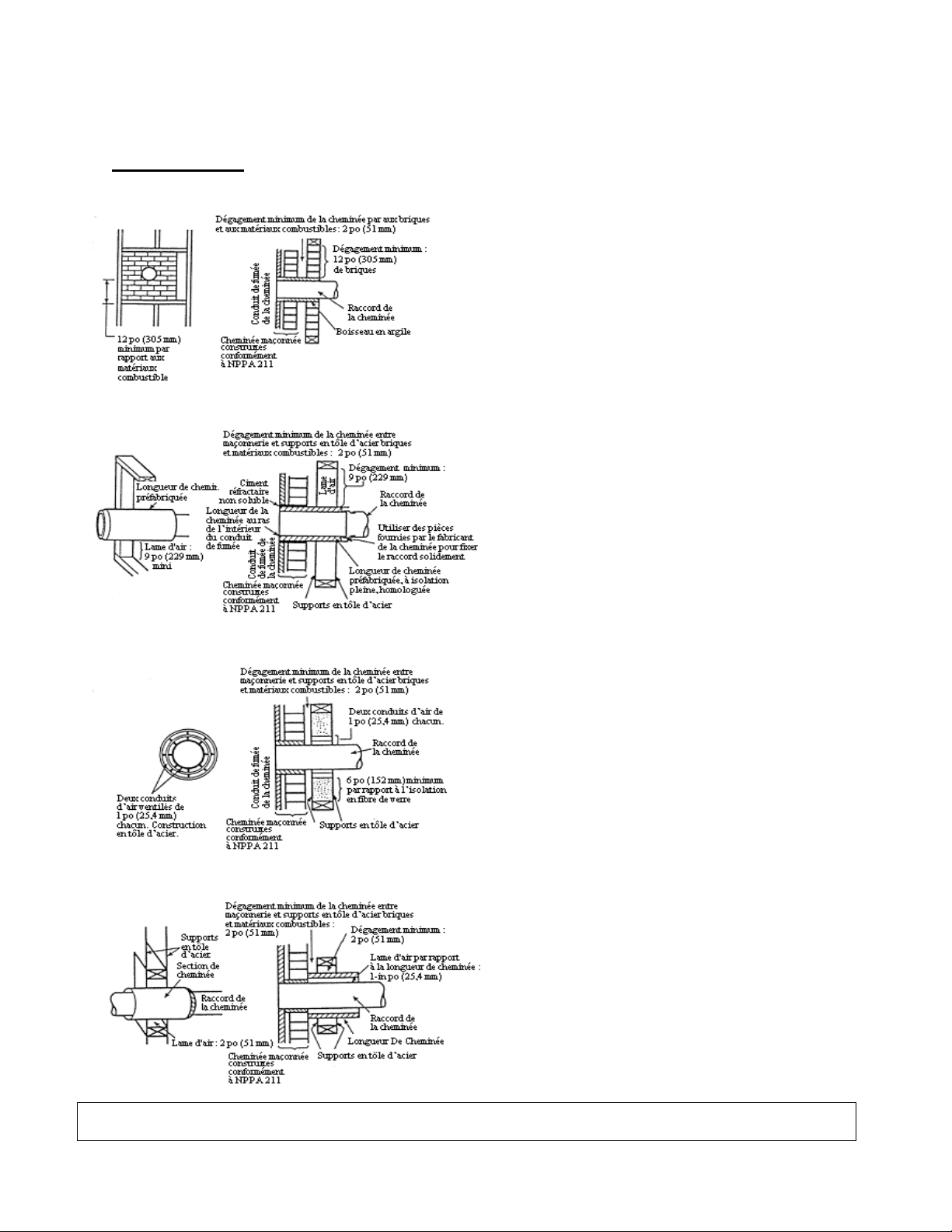
Page | 10
INSTALLATION
Traversées de mur
Raccordsdecheminéeetdégagements parrapportauxmurscom bustiblespo urlesappareilsdechauffageré sidentiels
Au Canada, l’installation doit respecter la norme CAN/CSA-8365 en cas de traversée de matériaux de construction
combustibles.
A En brique maçonnées ayant une épaisseur minimale de
3,5po entièrement encastrée dans le mur avec un cadre
et ayant une séparation minimale de 12po par des
briques entre le boisseau en argile et les matériaux
combustibles.Leboisseauenargiledoitallerdelasurface
extérieuredumurenbriquesjusqu’àlasurfaceintérieure
delagainedelacheminée;ildoitêtrecimentéfermement
enplace.
B Longueur de cheminée préfabriquée, à isolation pleine,
homologuée, ayant le même diamètre intérieur que le
raccord et ayant au moins 1po de revêtement isolant
avec une lame d'air minimale de 9po entre le mur
extérieur de la longueur de cheminée et les matériaux
combustibles.
C Raccorddecheminéeentôled’acier,d’épaisseurn°24au
minimum, avec un manchon d'emboîtement ventilé,
d’épaisseurn° 24 auminimum, ayantdeux conduits d’air
de 1po, séparé des matériaux combustibles par de
l’isolant en fibre de verre d’une épaisseur minimale de
6po. L’ouverture doit obligatoirement être couvert, et le
manchon d'emboîtement soutenu par un support en tôle
d’acierd’épaisseurn°24auminimum.
D Longueur de cheminée préfabriquée, à isolation pleine,
homologuée,ayantundiamètreintérieur2poplusgrand
que le raccord et ayant au moins 1po de revêtement
isolant, pour servir de gaine à un raccord à paroi simple
en tôle d’acier, d’épaisseur n° 24 au minimum, avec une
lame d'air minimale de 2po entre le mur extérieur de la
section de cheminée et les matériaux combustibles. La
longueur minimale de la section de cheminée doit
obligatoirement être une section de cheminée de 12po
espacéede1poduraccordaumoyendeplaquessupport
en tôle d’acier aux deux extrémités de la section de
cheminée. L’ouverture doit obligatoirement être
couverte, et la section de cheminée soutenue des deux
côtés avec des supports en tôle d’acier solidement fixés
auxsurfacesdesmurs,d’épaisseurn°24auminimum.Les
éléments servant à la fixation de la section de cheminée
nedevront
p
as
p
énétrerlachemisedelacheminée.
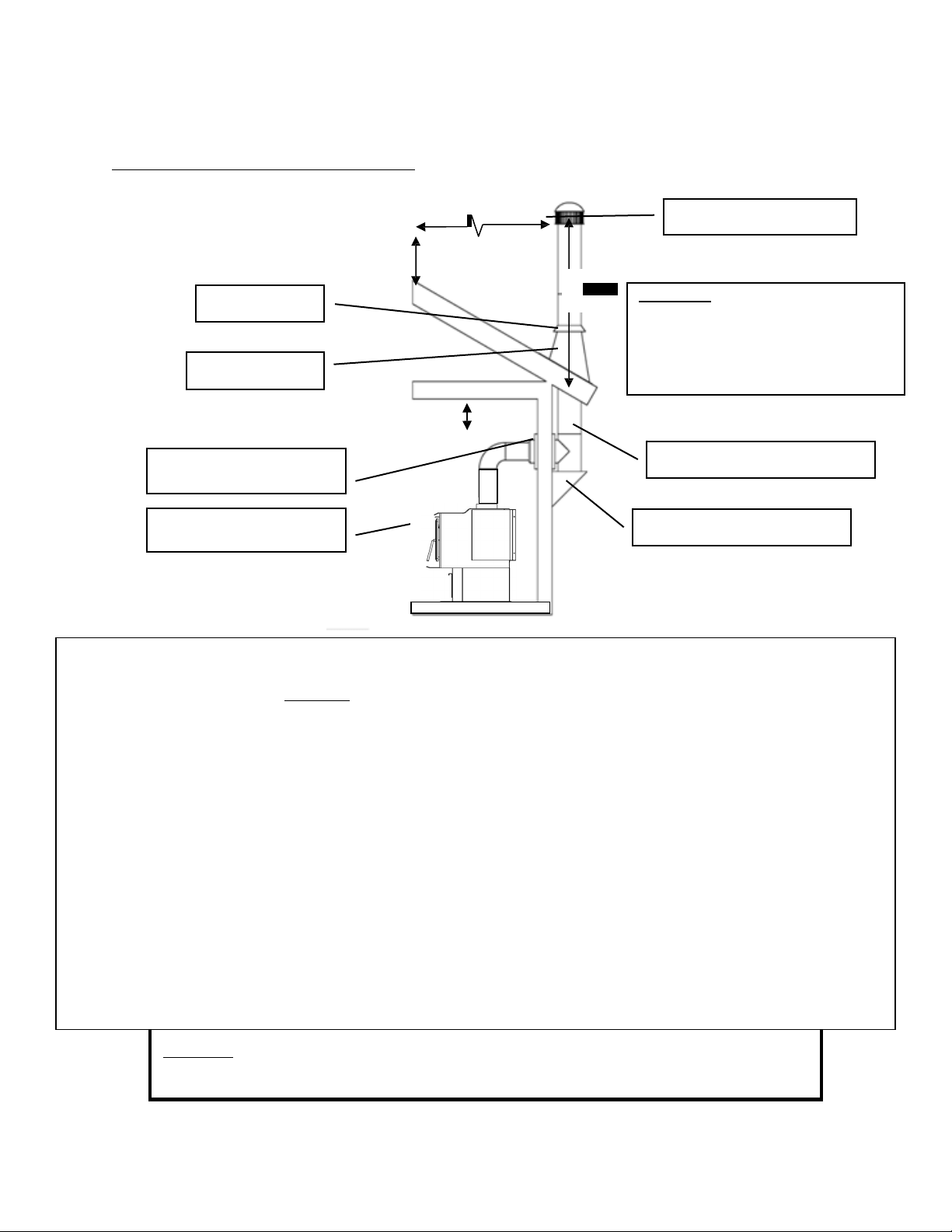
Page | 11
45,72cm
(18po)
0,61m
(2pi)
0,91m
(3pi)
INSTALLATION
Méthode deventilation approuvée 1:Àtraverslemuravecunecheminéepréfabriquée
Mitre
Solindetoit
Règle 10‐3‐2:Lesystèmedecheminéedoit
seterminerà0,91m(3pi)au‐dessusdu
pointoùsonaxecentraltraverseletoitET
lacheminéedoitseterminerà0,61m(2pi)
au‐dessusdetoutepartiedulogementdans
unrayonde3,05m(10pi)delacheminée.
SystèmedecheminéedeclasseA
RaccordenTetsupport
• Lessystèmesde cheminéepréfabriquésdoiventres pecterlesnormesULC‐S629(650°C)pourleCanadaetUL‐103HT(2100°F)
pourlesÉt a ts‐Unis.
• Cepoêleàboisesthomologuéseulementpouruneinstallationavecunsystèmede cheminéeavecraccorddecheminée
de15,24cm(6po)dediamètre.L ’installati ondecetappareilsurunecheminéepré fabri q uéeayantundiam èt resupérieur
à15,24cm(6po)diminueraletirageetpourraitentraînerunrendementinsuffisantdel’appareil.
• Respecteztouteslesexigencesdufabricantconcernantl’installationdusystèmedeventilationetlesdis tanc es
minim ales
nécessaires.
• Utiliseztroisvisàtôlepourchaquejointderaccorddecheminéeàparoisimple(vérifiezlesrecomm andations dufabricantlorsde
l’utilisati ond’unraccorddecheminéeàparoidouble).
• Perceztroistrousdanslabusedel’appareiletfixezleraccorddechemi néeàl’appareil
aumoyendevisàtôle(lestrousdevraient
généralementêtreprépercésdanslabuseàl’usine).
• Fixezcorre ctem e ntlesystèmedecheminéepréfabriquéàlamaisonenrespectantprécisémentlesinstructionsdufabricantdu
systèmedecheminéepréfabriqué.
• Évitezdetropnombreuxcoudesetparco urs horizontaux,carils
réduirontletirageetentraînero ntuneaccumulationaccruede
créosote.Lesparcourshorizontauxd’unraccorddecheminéenedoiventjamaisdépasser1,22metlalongueurtotaleduraccord
de cheminée ne doit pas dépasser 2,44 m si vous utilisez un raccord de cheminée noir à paroi simple. S'il est
nécessaire de
parcourirplusde2,44mdetuyaudeconnecteurdecheminée,untuyaudeconnecteurdecheminéenoiràdoubleparoidoitêtre
utilisé.
•
Desadaptateursspéciauxetdesraccordsàglissementsontoffertspouréviterd’a voiràcouperleraccorddecheminéeàparoisimple.
Unraccorddech em i née àparoidoubl e doitêtreutiliséaveccesraccordsàglissement,carilnepeutpasêtrecoupéenlongueur.
Veuillez noter:Lesschéma sd’installationsontfournisàtitrederéférenceuniquementetneson t pasàl’éc helle.Ils nesontpas
destinésàêtreutiliséscommedesplansuniverselsd’installation.Veuillezrespectertoutes lesexigencesrelativesau système de
ventilationetau x distancesminimalesnécessairesaveclesmatièrescombustibles,etsuivretous lescodeslocaux.
Manchond’emboîtement
mural
Raccorddecheminée
(àparoisimpleou
3,05m(10pi)
Capuchond’extrémité
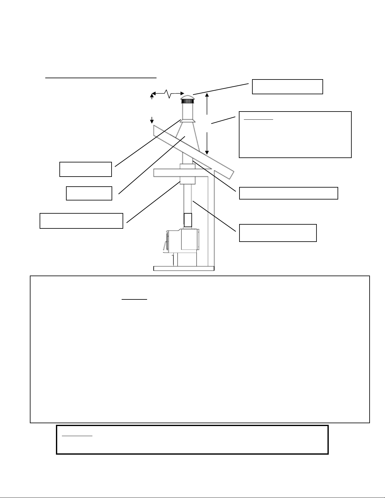
Page | 12
0,61m
(2pi)
0,91m
(3pi)
INSTALLATION
Méthode deventilation approuvée 2:Àtraversleplafond
3,05m(10pi)
Capuchond’extrémité
Mitre
Règle 10‐3‐2:Lesystèmedecheminéedoit
seterminerà0,91m(3pi)au‐dessusdu
pointoùsonaxecentraltraverseletoitET
lacheminéedoitseterminerà0,61m(2pi)
au‐dessusdetoutepartiedulogementdans
unrayonde3,05m(10pi)delacheminée.
Solindetoit SystèmedecheminéedeclasseA
Boîtedesupportdeplafond
Raccorddecheminée
(àparoisimpleoudouble)
•
LessystèmesdecheminéepréfabriquésdoiventrespecterlesnormesULC‐S629(650°C)pourleCanadaetUL‐103HT(2100°F)pour
lesÉtats‐Unis.
• Cepoêleàboisesthomologuéseulementpouruneinstallationavecunsystèmedecheminéeavecraccorddecheminée
de15,24cm(6po)dediamètre.
L’installationdecetappareilsurunecheminéepréfabriquéeayantundiamètresupérieurà15,24cm(6po)diminueraletirageet
pourraitentraînerunrendementinsuffisantdel’appareil.
• Respecteztouteslesexigencesdufabricantconcernantl’installationdusystèmedeventilationetlesdistances
minimales
nécessaires.
• Utiliseztroisvisàtôlepourchaquejointderaccorddecheminéeàparoisimple(vérifiezlesrecommandationsdufabricantlorsde
l’utilisationd’unraccorddecheminéeàparoidouble).
• Perceztroistrousdanslabusedel’appareiletfixezleraccorddecheminéeàl’appareil
aumoyendevisàtôle(lestrousdevraient
généralementêtreprépercésdanslabuseàl’usine).
• Fixezcorrectementlesystèmedecheminéepréfabriquéàlamaisonenrespectantprécisémentlesinstructionsdufabricantdu
systèmedecheminéepréfabriqué.
• Lalongueurtotaleduraccorddecheminéenedoitpas
dépasser2,44m.Danslecasd’unplafondcathédrale,lesystèmede
cheminéepréfabriquépeutdépasserde2,44màpartirdudessusdel’appareilsivousutilisezuntuyauderaccordementàune
paroi.S'ilestnécessaired'utiliserplusde2,44mdetuyaudeconnecteurdecheminée,un
tuyaudeconnecteurdecheminéenoirà
doubleparoidoitêtreutilisé.
•
Desadaptateursspéciauxetdesraccordsàglissementsontoffertspouréviterd’avoiràcouperleraccorddecheminéeàparoisimple.Un
raccorddecheminéeàparoidoubledoitêtreutiliséaveccesraccordsàglissement,carilnepeutpasêtrecoupéenlongueur.
Veuillez noter:Lesschéma sd’installationsontfournisàtitrederéférenceuniquementetneson t pasàl’éc helle.Ils nesontpas
destinésàêtreutiliséscommedesplansuniverselsd’installation.Veuillezrespectertoutes lesexigencesrelativesau système de
ventilationetau x distancesminimalesnécessairesaveclesmatièrescombustibles,etsuivretous lescodeslocaux.
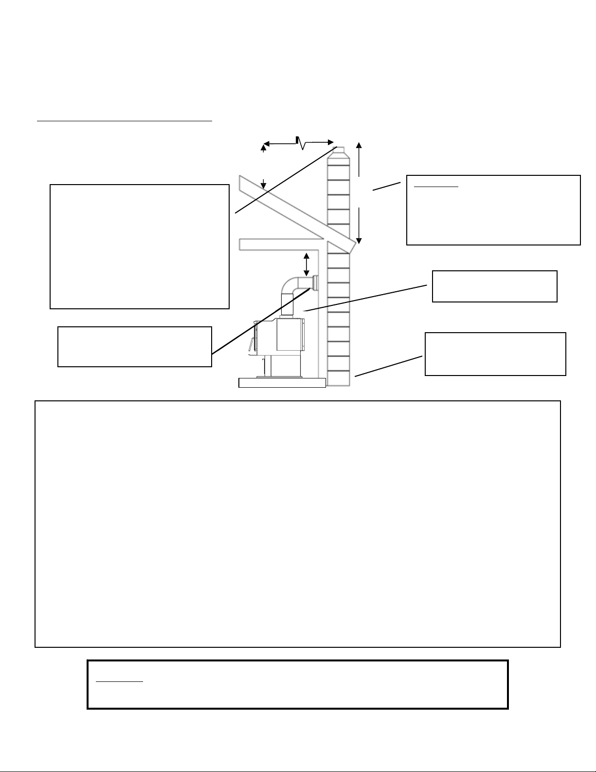
Page | 13
0,61m
(2pi)
45,72cm
(18po)
0,91m
(3pi)
INSTALLATION
Méthode deventilation approuvée 3:Systèmedecheminéeenmaçonnerieintérieurouextérieur
3,05m(10pi)
Lasuperficiedelasectiontransversaledela
doubluredecheminée(longueurxlargeur)
nedoitpasdépasserdeplusdedeuxfois
lasuperficiedelasectiontransversal ede
labuse(2x182,39cm²=364,84cm²
[2x28,27po²=56 ,5 5po²]).Siladou blure
decheminée
dépasse 143,64cm2
(56,55po²),vousdevezutiliserunenouvelle
doubluredecheminéede13,9 7cm(5,5po)
oude15,24cm(6po).
Règle10‐3‐2:Lesystèmedecheminéedoit
seterminerà0,91m(3pi)au‐dessusdu
pointoùsonaxecentraltraverseletoitET
lacheminéedoitseterminerà0,61m(2pi)
au‐dessusdetoutepartiedulogementdans
unrayonde3,05m(10pi)delacheminée.
Raccorddecheminée
(àparoisimpleoudouble)
Manchond’emboîtementen
maçonnerieavecdégagement
adéquatauxmatièrescombustibles
Lesportesdenettoyagedes
cendresdoiventêtrehermétiques
pouréviterunfaibletirage.
• Observezlesrèglesindiquéesci‐dessusconcernantladimensionmaximaleadmissibledeladoubluredecheminée.
L’installationdecetappareilsurunecheminéeenmaçonneriedontlasuperficiedelasectiontransversaledépasse
364,84cm²
(56,55po²)diminueraletirageetpourraitentraînerunrendementinsuffisantdel’appareil.
• Utiliseztroisvisàtôlepourchaquejointderaccorddecheminéeàparoisimple(vérifiezles
recommandationsdufabricantlorsdel’utilisationd’unraccorddecheminéeàparoidouble).
• Perceztroistrousdansla
busedel’appareiletfixezleraccorddecheminéeàl’appareilaumoyendevisàtôle(lestrous
devraientgénéralementêtreprépercésdanslabuseàl’usine).
• Évitezde tropnombreux coudes etparcourshorizontaux, car ils réduiront le tirage et entraîneront une accumulation
accrue de créosote. Les parcours
horizontaux d’un raccord de cheminée ne doivent jamais dépasser 1,22 m et la
longueur totale du raccord de cheminée ne doit pas dépasser 2,44 m si vous utilisez un raccord de cheminée noir à
paroi simple. S'il est nécessaire de parcourir plus de 2,44 m de tuyau de connecteur de
cheminée, un tuyau de
connecteurdecheminéenoiràdoubleparoidoitêtreutilisé.
• Unmanchond’emboîtementhermétiqueestessentielpourobtenirunrendementadéquatdel’appareiletrendre
l’installationsécuritaire.Utilisezunadaptateurdeconceptionadéquatepourrelierleraccorddecheminéeàparoisimple
oudoubleaumanchon
d’emboîtementenmaçonnerie.
• Avantd’utiliserl’appareil,faitesinspecterlacheminéeenmaçonnerieexistanteafindevousassurerquesonutilisationest
sécuritaireetquelesdistancesminimalesaveclesmatériauxcombustiblessontrespectées.Unramoneurcompétentpeut
effectuercetteinspection.
• Lescheminéesenmaçonnerieextérieuressubissentsouventle
contre‐tiraged’airfroidetontunfaibletiragemêmesielles
respectentlesrèglesdesuperficiedelasectiontransversale.Danscecas,ilpeutêtrenécessaired’utiliserunedoublure
isoléede15,24cm(6pi).
Veuillez noter:Lesschéma sd’installationsontfournisàtitrederéférenceuniquementetneson t pasàl’éc helle.Ils nesontpas
destinésàêtreutiliséscommedesplansuniverselsd’installation.Veuillezrespectertoutes lesexigencesrelativesau système de
ventilationetau x distancesminimalesnécessairesaveclesmatièrescombustibles,etsuivretous lescodeslocaux.
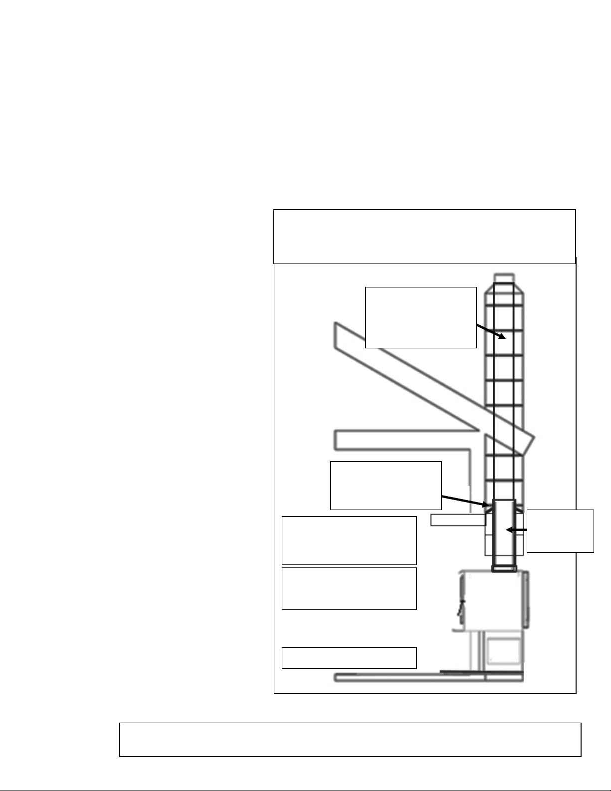
Page | 14
INSTALLATION
INSTALLATION DANS UN FOYER EN MAÇONNERIE
Préparation
N’oubliez pas que ce type d’installation rend difficile le changement fréquent de vitesse du ventilateur. Nous
vous recommandons de choisir une vitesse de ventilateur et de maintenir ce réglage, car il sera difficile de le
modifier en raison de l’installation étroite. AVERTISSEMENT : NE TENTEZ PAS DE RÉGLER LE
VENTILATEUR DURANT LE FONCTIONNEMENT. VOUS RISQUEZ DE SUBIR DES BRÛLURES LORS DU
CONTACT AVEC L’APPAREIL. ATTENDEZ QUE L’APPAREIL SOIT COMPLÈTEMENT REFROIDI AVANT
DE RÉGLER LE VENTILATEUR.
Mesurez l’âtre pour vous assurer qu’il est d’une largeur suffisante pour loger l’appareil.
L’appareil doit avoir un dégagement de 91,44cm entre la partie supérieure du poêle et le manteau de
cheminée selon la norme211 de la NFPA.
Pour les États-Unis: L’âtre doit dépasser
d’au moins 406,4mm à l’avant de l’ouverture
pour le combustible.
Pour le Canada: L’âtre doit dépasser d’au
moins 450mm à l’avant de l’ouverture pour
le combustible.
Inspectez l’âtre pour vous assurer qu’il est
fabriqué d’un matériau incombustible comme
la brique ou la pierre. N’installez pas ce
poêle sur un âtre fabriqué d’une charpente
en bois couverte de briques ou de pierres et
n’installez pas cet appareil dans un foyer
dont le dégagement est nul(0). Le fabricant
ne sera pas tenu responsable d’un accident
causé par l’installation de ce poêle sur un
âtre fabriqué avec un matériau combustible.
Inspectez votre foyer pour vous assurer qu’il
est en bon état de fonctionnement et qu’il
est exempt d’obstructions.
Avant l’installation, retirez le registre existant
ou fixez-le à l’aide d’un câble pour le
maintenir ouvert de façon sécuritaire.
Ventilation du poêle– raccordement
direct
Lorsque cet appareil est raccordé
directement, un tuyau de calibre24 d’un
diamètre de 15,24cm doit être utilisé à partir
du poêle jusqu’à l’ouverture du registre.
(REMARQUE: Le raccord de cheminée
doit être fixé à l’appareil avec au moins
trois (3) vis, et troisvis doivent être
utilisées pour fixer chaque section
adjacente.)
Nous recommandons fortement l’utilisation
d’une doublure de 15,24cm sur l’ensemble
de la cheminée pour assurer un tirage
approprié. Il sera ainsi nécessaire d’obturer
la zone ouverte des deuxcôtés du tuyau
traversant l’ouverture du registre au moyen
d’une tôle ou d’un isolant en fibre de verre à
l’épreuve du feu dans les zones ouvertes (ni
papier ni combustible). Vous devez vous
assurer que le tirage de la cheminée s’effectue par le poêle et non autour du tuyau de raccord.
91,4cm(36po)minimum
àpartirdedupoêleàbois
aumanteau
Voirlesexigencesdufoyer
Retireroucâblerle
registredecheminée
ouvert
Revêtementde
15,24cm(6po)
fortement
recommandée
Tuyaude
raccordement
decheminée
Vueencoupedela
cheminée
Règle10‐3‐2:Lesystèmedecheminéedoitseterminerà0,91m
au‐dessusdupointoùsonaxecentraltraverseletoitETlacheminée
doitseterminerà0,61mau‐dessusdetoutepartiedulogementdans
unra
y
onde3
,
05mdelacheminée.
Nousvousrecommandonsfortementquecetteopérationsoiteffectuéeparunprofessionnel.
Communiquezégalementaveclesautoritéslocalespourvousassurerquetouslescodessontobservés.
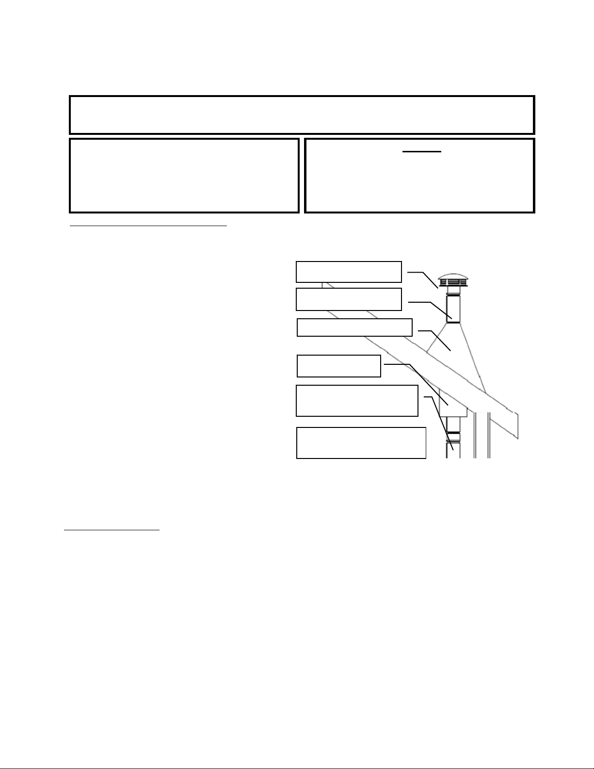
Page | 15
INSTALLATION
AVERTISSEMENT
N’INSTALLEZPASCETAPPAREILDANSUNECHAMBREÀCOUCHER.
MISEENGARDE
L’INTÉGRITÉSTRUCTURELLEDUPLANCHER,DES
MURS,DUPLAFONDETDUTOITDELAMAISON
PRÉFABRIQUÉEDOITÊTREPRÉSERVÉE.
Attention
NETIREZJAMAISl’aircomburantextérieur:d’une
cavitéd’unmur,d’unplancheroud’unplafond,ou
d’unespacecloscommeungrenier,ungarageouun
videsanitaire.
Installationdansune maison mobile(ÉTATS‐UNISSEULEMENT,NONAPPROUVÉEPOURUNE
INSTALLATIONDANSUNEMAISONMOBILEAUCANADA)
• LepoêleàboisDOITêtrefixéaupl anc herdelamaisonmobileàl’aidedetir e‐fondsdispos ésdanslestrous
prévusàceteffetdanslapartieinférieurede
l’appareil.Lessystèmesdechauffageventilés
àl’airextérieurdoiventêtrefixésàla
structuredanslaquelleilsse
trouvent.Utilisez
unfildecuivren°8pourfixerlepoêleau
châssisdelamaisonmobile.
• Lepoêleàboisdoitêtreraccordéausystème
decheminéeàl’aided’unraccorddecheminée
àparoidoublehomologuéULpourl’utilisation
dansunemaisonmobileoupréfabriquée.
•
Observezattentivementtouteslesindications
relativesaudégagementmentionnéesàla
sectionappropriéeduprésentguideET
respectezlesexigencesdufabricantdusystème
deventilationconcernantlesdistances
minimales.Deplus,assurez‐vousquelesystème
deventilationestapprouvépouruneutilisation
dansunemaisonmobile.
• L’installation
doitêtreconformeàlanorme
ManufacturersHome&SafetyStandard(HUD)
CFR3280,partie24,desÉtats‐Unisainsiqu’aux
codeslocauxenvigueur.
Chapeaudecheminéeet
pare‐étincelles
Systèmedecheminéede
classeA
Solindetoitetmitre
Protecteurdesolive
etcoupe‐feu
Raccorddecheminéeàparoi
doubleapprouvépourles
maisonsmobiles
Utilisezdelasiliconepourcréer
uncoupe‐vapeuràl’endroitoùla
cheminéepasseàl’extérieur.
Air comburant extérieur
• L’utilisationdel’aircomburantextérieurestobligatoirelorsdel’installationdecepoêleàboisdansune
maisonmobileoupréfabriquée.
• Letuyauderaccordementd’airextérieurdépassedelapartieinférieurecentraledupoêle;unetrousse
offerteparEngland’sStoveWorks,Inc.estconçuepourraccordercetappareil
àl’aircomburantextérieur.
(N°depièceAC‐OAK3)
• S’iln’estpaspossibled’utiliserlatroussederaccordementd’airextérieurAC‐OAK3pourl’installation
devotrepoêle,vouspouvezutiliserd’autresmatériauxàconditiond’observerlesrèglessuivantes:
o Letuyauutilisépourleraccordementd’airextérieurdoit
êtreenmétaletavoiruneépaisseur
minimalede0,53mm(0,0209po)(acierdouxdecalibre25)etundiamètreintérieurd’environ
69,85mm(2,75po).
o Prévoyezdecourteslongueursdetuyauetutilisezunefixationsurchaquejointdetuyau.
o Unécranouunautredispositifde
protectiondoitêtreplacéàl’extrémitédutuyaude
raccordementàl’airextérieurafind’éviterquelapluie,desdébrisoudesanimauxnuisiblesne
pénètrentdanslesystèmedetuyauterie.Inspectezl’admissiond’aircomburantextérieurtousles
moispouréviterlesblocagesetl’accumulationdedébris.
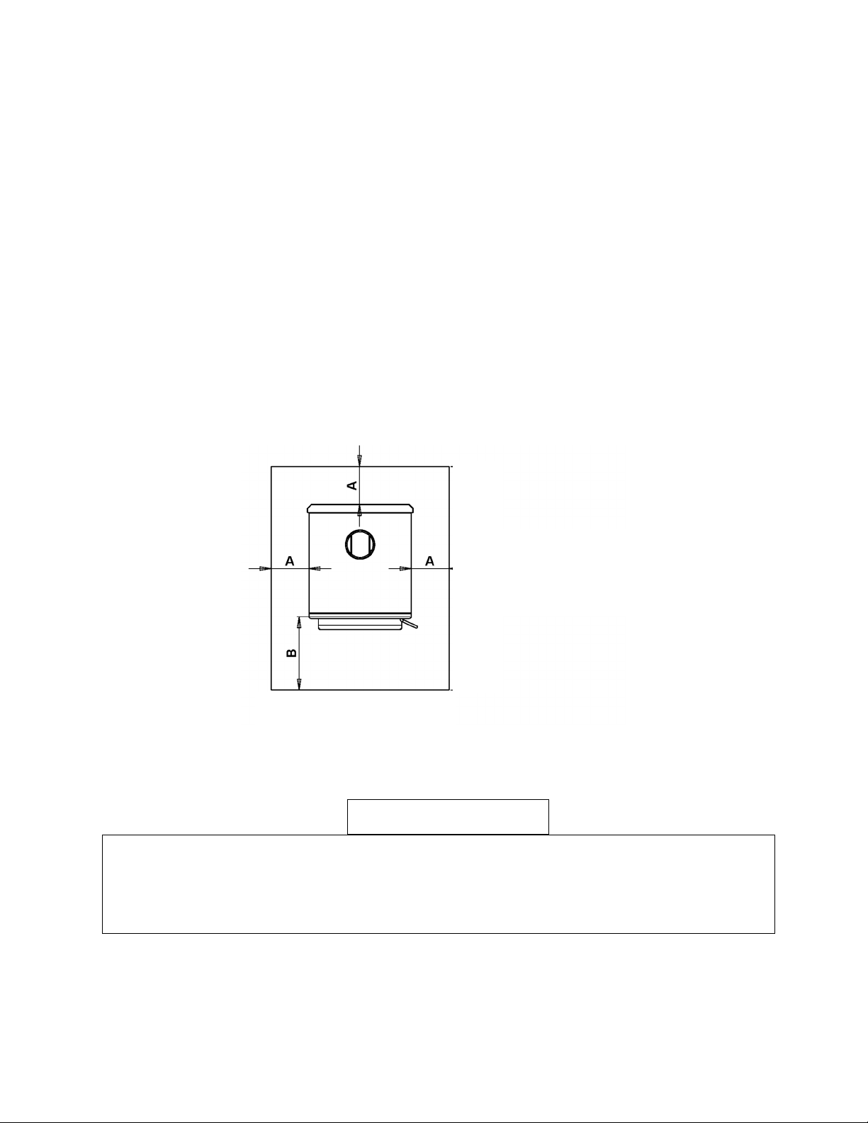
Page | 16
PROTECTIONDUPLANCHER
• Danslecasoùle poêleàboisestinstallésurunplanchercombustible,ilestnécessaired’utiliserunprotecteur
deplancherave c unfacteurRnoninférieurà1.0conformeàlanormeUL(UL CauCanada)..Sileplanchersur
lequellepoêledoitêtreinstalléest
déjàincombustible(parexemple,leplancherenbétond’unsous ‐sol),
aucunprotecteurde planchern’estrequis(vouspouveztoutefoisinstallerunprotecteurdeplancherdécoratif).
• Lorsquevousutilisezunprotecteurdeplancher,n’oubliezpasquelepoêleestnonseulementlourd,mais
qu’ilimposeégalementdesécartsde
températureauprotecteurdeplancher,cequipeutendommagerles
carreauxetdétacherlesjointsdemortieretdecoulissituésprèsdupoêle.
• LeprotecteurdeplancherdoitêtrehomologuéULoul’équivalent(ULCauCanada)etdoitêtre
incombustible.Untapispourâtren’estPASapprouvépour
remplacerunprotecteurd’âtreapproprié.
• PourlesÉtats‐Unis:Leprotecteurdeplancherdoitdépasserd’aumoins40.6cm(16po)àl’avantde
l’ouverturepourlecombustible,de20.3cm(8po)surlescôtésdel’ouverturedeporteetde20.3cm(8po)
àl’arrière
del’appareil.
• PourleCanada:Leprotecteurdeplancherdoitdépasserd’aumoins450mmàl’avantdel’ouverturepour
lecombustible,de200mmsurlescôtésdel’ouverturedeporteetde200mmàl’arrièredel’appareil.
• Leprotecteurdeplancherdoitdépasserde50,8mm(2po)dechaquecôtédesparcoursdeventilation
horizontauxetseprolongerdirectementsoustouttuyaudeventilationvertical.
MISEENGARDE
N’UTILISEZJAMAISD’ESSENCE,DECOMBUSTIBLEPOURLAMPEAPPARENTÉÀL’ESSENCE,DE
KÉROSÈNE,DELIQUIDED’ALLUMAGEPOURCHARBON,NIAUCUNLIQUIDESIMILAIREPOURALLUMER
OURAVIVERUNFEUDANSCETAPPAREILDECHAUFFAGE.CONSERVEZDETELSLIQUIDESÉLOIGNÉS
DEL’APPAREILDECHAUFFAGELORSQUECELUI‐CIFONCTIONNE.DEPLUS,NEDISPOSEZJAMAIS
D’ALLUME‐FEUXSURUNESURFACECHAUDENISURDESTISONSDANSLE POÊLE.
0,98m
1,19
____m
(____
8
p
o
)
____m
(____po)
A:É.‐U.,20.3cm(8po)
Canada,200mm(8po)
B:É.‐U.,40.6cm(16po)
Canada,450mm(18po)

UTILISATION
Premiers feux
• Cepoêleàbois,conçupourdurerlongtemps,estfabriquéenacierépaisetenfonte.Cependant,
pouréviterqu’unetensionthermiqueexcessivesoitinduiteaumétalpendantlepremierfeu,ilfaut
troispetitsfeuxderodage,ens’assurantquechaquefeusoitlégèrementpluschaudquele
précédent.Cesfeuxderodageneservirontpasseulementàacclimaterlepoêleauxtempératures
élevées,maisilsaiderontaussiàfairedurcirlentementlapeinturepourpoêlerésistantauxhautes
températures,cequipermettraaufinidequalitésupérieurededurerplusieursannées.N'oubliez
pasd'ouvriruneporteet/ouunefenêtrepourventilerlazone.
NOUSRECOMMANDONSFORTEMENTdebrûlervosincendiesàl'extérieur,carlapeintureetles
huilesdefabrication«brûleront»quelquepeul'extérieurdupoêlependantcetemps.Sivousles
brûlezàl'intérieuravecvotresystèmedecheminée,ouvrezlesportesetlesfenêtres
pour
ventiler.
• Cepoêleestmunid’uneseuletigedecommanded’airquirégulariseletauxdecombustiondubois.
Lorsqueledispositifcoulissantdecommanded’airprimaireestenfoncécomplètementvers
l’intérieur,lepoêlechauffepluslentementetfournitdelachaleurpluslongtemps.Àl’inverse,
lorsqueledispositifcoulissantdecommanded’airesttirécomplètementversl’extérieurde
l’appareil,l’appareilchauffeplusviteetfournitunechaleurplusintensesurunepériode
relativementpluscourte.N’essayezpasdemodifierleréglagedecommanded’airpeuimportela
raison.
• Lepremierfeuderodagedevraitêtreungrandfeudeboisd’allumagepermettantaupoêle
d’atteindreunetempératurede148,89°C(300°F)mesuréeparunthermomètremagnétiquedu
côtégaucheoudroitdupoêle,au‐dessusdela porte.Unefoiscettetempératureatteinte,laissezle
feus’éteindreengardantlacommanded’airouverte.Lesdeuxièmeettroisièmefeuxderodage
devraientêtreunpeuplusimportantsenajoutantquelquespetitsmorceauxsecsaubois
d’allumage.Latempératureà
atteindrependantcesfeuxsesitueentre176,67°Cet232,22°C
environ(entre350et450°F);nelaissezpaslefeudépassercettetempérature.
Fonctionnementcontinu‐Fonctionnementquotidien aprèsvotrepremierfeu
Allumage
Chargezlachambredecombustionavecdedémarragefendu.
Surleboisdedémarrage,ajoutezdeboisd'allumagesec,diviséentrèspetitsmorceaux.
Allumezlepetitboisparlehautjusqu'àcequ'uneflammes'établisse.
Fermezlaporteetréglezl'amortisseursurhaut(complètement
ouvert)pourréduirelaquantitéde
fumée.
Feuélevée
Nelaissezpaslacendreetlesbraisess’accumulerplushautqueletroud’airdanslaniche(voirla
dispositiondesbriques,page33).
Chargezduboissurlelitdecharbonaprèsavoircoupéetemballéles
charbons,sinécessaire.
Fermezlaporteetréglezl'amortisseursurhaut(complètementouvert)etréglezleventilateursur
hautevitesse.
Feufaible
Nelaissezpaslacendreetlesbraisess’accumulerplushautqueletroud’airdanslaniche(voirla
dispositiondesbriques,page33).
Chargez
duboissurlelitdecharbonaprèsavoircoupéetemballélescharbons,sinécessaire.
Fermezlaporteetréglezl'amortisseursurhaut(complètementouvert)etréglezleventilateursur
hautevitesse.
Après15minutes,réglezl'amortisseursurfaible(complètementfermé)etréglezleventilateursur
faible
vitesse.
Feumoyen
Nelaissezpaslacendreetlesbraisess’accumulerplushautqueletroud’airdanslaniche(voirla
dispositiondesbriques,page33).
Chargezduboissurlelitdecharbonaprèsavoircoupéetemballélescharbons,sinécessaire.
Fermezlaporte,
réglezl'amortisseursur1/2ferméetréglezleventilateursurbassevitesse.
Après15minutes,réglezleventilateursurfaiblevitesse.
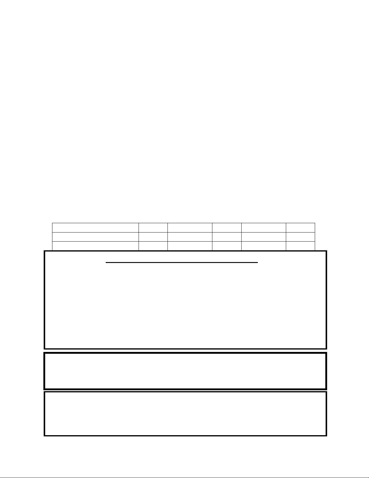
Page | 18
FONCTIONNEMENT
• England’sStoveWorks,Inc.recommandetoujoursl’utilisationd’unthermomètredepoêlemagnétique
afindesurveillerlatempératuredel’appareil.Pourutiliserunthermomètredepoêlemagnétique,
installez‐leau‐dessusdelaporteducôtégaucheoudroitdupoêleetutilisezlestempératuressuivantes
commeguidepourdéterminerle
tauxdecombustionetledegrédechaleurémiseparlepoêle:
o Lefonctionnementnormaldupoêleàboissesitueentre177°C(350°F)et288°C(550°F).De
177°C(350°F)à232°C(450°F),ledegrédechaleurseradefaible
àmoyenetde232°C(450°F)
à288°C(550°F),ledegrédechaleurserademoyenàélevé.Lefonctionnementdupoêleà
316°C(600°F)estlatempératuremaximaleadmissiblepouruneutilisationcontinue.
L’utilisationdupoêleàcettetempératureavecuntauxdecombustion
élevépourdelongues
périodespourraitl’endommager.Lefonctionnementdel’appareilàunetempératureégaleou
supérieureà398°C(750°F)estconsidérécommeunesurchauffeetendommageral’appareil.
• Leventilateurdeconvectionde l’airenoptionaétéconçupourextraireunmaximumdechaleurdupoêle
afind’obtenirlemeilleurtr ansfe rt dechaleurpossibledanslapièce.Étantdonnéqueleventilateurestsi
efficaceàretirerdelachaleurdel’appareil,ilesttr è simportantdelefairefonctionnerseulementaprès
qu’unenouvellechargedeboisaeule tempsdebrûler pendantaumoins
30minutes.Lefaitdelaisseràune
nouvellechargedeboisletempsdebrûler avantd’utiliserleventil ateur perm et àl’appareild’atteindreune
températuredefonctionnementadéquateetpermetausystèmede combustionsecondairedefonctionner
correctement.Suivezéga l em ent lesdirectives ci‐dessouspourconnaîtrelesvitessesappropriéesdu
ventilateur.
• Lorsquevousutilisezleventilateurdeconvectiondel’airenoption(n°depièceAC‐16oulanouvelleversion
AC‐30),celui‐cidoitfonctionnercommesuit,selonledegrédechaleur:
Tauxdecombustion
Élevé Moyen/élevé Moyen Moyen/élevé Bas
VitesseduventilateurAC‐16 Élevée Élevé Basse Basse Basse
VitesseduventilateurAC‐30 Élevée Moy./élevée Moyenne Moy./élevée Basse
Créosote – Formation et importance du retrait
Lorsqueleboisbrûlelentement,ilproduitdugoudronetd’autresvapeurs
organiquesquisecombinentavecl’humiditéévacuéepourformerlacréosote.
Lesvapeursdecréosotesecondensentdansleconduitdefuméerelativementfroid
lorsquelefeuseconsumelentement.Parconséquent,desrésidusdecréosote
s’accumulentsurle
conduitdefumée.Lorsqu’elles’enflamme,cettecréosote
produitunfeuextrêmementchaud.Lacheminéeetleraccorddecheminéedoivent
êtreinspectésaumoinstouslesdeuxmoispendantlasaisondechauffageafinde
vérifiersiuneaccumulationdecréosotes’estproduite.Encasd’accumulationde
créosote,celle‐ci
doitêtreretiréeafinderéduireleris
q
uedefeudanslacheminée.
VOUSNEDEVEZPASUTILISERDEGRILLENIDECHENET,NISURÉLEVERLEFEUDE
QUELQUEFAÇONQUECESOIT–INSTALLEZLEBOISDIRECTEMENTSURL’ÂTRE
N’UTILISEZPASL’APPAREILAVECLAPORTEPRINCIPALEOUVERTE–VOUSRISQUERIEZ
DEPROVOQUERUNESURCHAUFFE
Encasdefeucauséparuneaccumulationdecréosoteoudesuie(feudecheminée), fermez
lacommanded’airsituéesurlepoêle,communiquezavecleserviced’incendielocaletquittez
leslieux!Neversezpasd’eausurlefeu!Communiquezavecleserviced’incendielocalpour
connaîtrelamarche
àsuivreencasdefeudecheminéeetpréparezunpland’évacuation
sécuritairepourvousetvotrefamille.

Page | 19
FONCTIONNEMENT
Consignes desécurité supplémentaires
MISEENGARDE:Lorsquevousajoutezducombustibleaupoêle,leventilateurdoitêtreéteint.
• L’installationdedétecteursdefuméeestfortementrecommandéelorsquevousinstallezcet
appareiloutoutautretyped’appareilàcombustiblesolide.Lesdétecteursdefuméedoivent
êtreinstallésprèsdechaquepiècedelamaison,voiredanscelles‐ci,plusparticulièrement
pourleschambresàcoucher.
• Undétecteurdefuméepeutêtreinstallédanslamêmepiècequelepoêleàboisenstéré.
Toutefois,s’ilesttropprèsdel’appareil,ilpourraitémettredefaussesalarmesàcausedesfilets
defuméequipeuvents’échapperàl’allumage dufeuoupendantleprocessusderechargement.
Pour
cetteraison,ledétecteurdefuméeinstallédanslamêmepiècequel’appareildevraitêtre
placéaussiloindel’appareilquelapiècelepermet.
• Cepoêleestuniquementconçupourbrûlerduboisnaturel.Lacombustiond’unboisdurséché
àl’air,plutôtqu’unboisrésineuxouunboisdurfraîchementcoupé,accroîtlerendementdupoêle
enplusderéduirelesémissionsauminimum.NEFAITESPASBRÛLERdesdéchets,dugazoncoupé
oudesrésidusdejardinage,desmatériauxcontenantducaoutchouc,ycomprisdespneus,
desmatériauxcontenantduplastique,desdéchetsdeproduitspétroliers,delapeintureoudu
diluantàpeinture,desproduitsbitumineux,desmatériauxcontenantdel’amiante,desdéblais
oudesdébrisdeconstruction,destraversesde
chemindeferou duboistraitésouspression,
dufumieroudesrestesd’animaux,duboisdegrèveimprégnéd’eausaléeoudesmatériaux
préalablementsaturéseneausalée,desproduitsdepapier,ducarton,ducontreplaquéoudes
panneauxdeparticules.L’interdictiondebrûlercesmatériauxnevousempêche
pasd’ utiliser
desallume‐feuàbasedepapier,decarton,desciure,decireoud’autressubstancessemblables
pourallumerunfeudanslepoêleàbois.Lacombustiondecesmatériauxpeutcompromettre
l’efficacitédupoêleetproduiredelafuméeetdesvapeurstoxiques.
• Lefaitdebrûlerd’autrescombustiblesqueleboisenstéré,plusparticulièrement ducharbon
etducharbondebois,peutentraînerdesémanationsàfortesconcentrationsenmonoxyde
decarbonedansl’habitation.Pourcesraisons,nefaitesJAMAISbrûlerducharbonnidu
charbondeboisdanscepoêleà
boisenstéré.L’installationd’undétecteurdemonoxydede
carboneetlaconnaissancedessymptômesd’unempoisonnementaumonoxydedecarbone
peuventréduirelesrisquesliésaumonoxydedecarbone.
• Cetappareilestconçupourfonctionneruniquementlorsquelaportedechargementestfermée
etbienverrouillée.Lefonctionnementdecetappareilaveclaportedechargementouverteou
malverrouilléeentraîneral’acheminementverslefeud’unequantitéexcessived’aircomburant,
cequiferaaugmenterdangereusementlatempératuredel’appar eil.
Unetempératureélevée
peutendommagerl’appareil,entraînerl’annulationdelagarantieetenflammerlacréosote
accumuléedanslesystèmedecheminéedurantlesfeuxàcombustionlenteprécédents.
• Letiragenaturelquitirel’airdansl’appareiletpermetaufeudebrûlerutilisel’airintérieurdu
logementpourassurerlacombustion,àmoinsquel’appareilnesoitraccordéàun esourced’air
comburantextérieur.Leshottesàévacuationdec uis in ière ,lesfournaisesetlesautresapparei ls de
circulation
d’airdanslamaisonretirentaussidel’airdulogement.Silaquantitéd’airfiltréoud’air
entrantdanslamaisonestinférieureàcelleretiré e delamaison,unepressionnégativepeutse
produire.
N’ENTREPOSEZPASDECOMBUSTIBLESPLUSPRÈSQUELESDÉGAGEMENTSSPÉCIFIÉSOU
DANSL’ESPACENÉCESSAIREAUCHARGEMENTDUPOÊLEETAURETRAITDESCENDRES.

Page | 20
• Étantdonnéquecetappareilfonctionneavecuntiragenaturel,cesera souventlepremierappareil
touchéparunepressionnégative.Sidelafuméeestexpulséehorsdesjointsderacc ordde
cheminéeoudusystèmed’inductiond’airdel’appare il, c’estprobablementparcequelepoêle
combatlapression
négativedulogement.L’ouverturepartielled’une fenêtreoud’uneporteprès
del’appareilpeutaideràégali se rlapression.Finalement,ilpourraitêt renécessaired’ajouterune
sourced’aircomburantexté rieur dégagéepourassurerlefonctionnemen tadéquatdel’appareil.
• Sil’appareilestraccordéàl’airextérieur,assurez‐vousdesurveillerlesaccumulationsdeglace
oudeneigepouvantbloquerl’entréed’airextérieurdusystèmedecombustion.Pouréviterun
manqued’airpourl’appareil,leraccordd’airextérieurnedoitpasêtreobstrué.
Pratiquesdechauffageauboissécuritaires
Unefoisquevotreappareildechauffageauboisestcorrectementinstallé,suivez
cesdirectivespourassurerunfonctionnementsécuritaire:
• Teneztouslesarticlesdemaisoninflammables(draps,meubles,journauxet
livres)loindel’appareil.
Pourallumerunfeu,utilisezuniquementdupapierjournal,duboisd’allumageet
unallume‐feuentièrementnatureloubiologique.N’utilisezjamaisd’essence,de
kérosèneoud’allumoiràcharbonpourallumerunfeu.
Nebrûlezpas
debûcheshumidesouvertes(nonséchées).
N’utilisezpasdebûchesfaitesdecireoudesciuredeboisdansvotrepoêleàbois,car
ellessontconçuespourdesfoyersouverts.Sivousutilisezdesbûchesfabriquées,
prenezcellesquisontfaitesdesciuredeboiscompresséeà100
%.
Faitesdesfeuxchauds.Pourlaplupartdesappareilsdechauffageaubois,unfeuqui
couven’estnisécuritaireniefficace.
Gardezferméeslesportesdevotreappareildechauffageauboissaufpourajouterdes
bûchesoualimenterlefeu.Desproduitschimiquesnocifs,commele
monoxydede
carbone,peuventêtrelibérésdansvotredomicile.
Retirezrégulièrementlescendresdevotreappareildechauffageauboisdansun récipient
enmétaldoté d’uncouvercle.Rangezlerécipientcontenantlescendresàl’extérieur,sur
unedalledecimentoudebrique(etnonpassuruneterrasse enboisniàproximitéde
bois).Consultezlesinstructionssurleretraitdescendres dansleguided’utilisation.
Gardezunextincteurd’incendieàportéedelamain.
N’oubliezpasdeconsulterlesprévisionslocalessurlaqualitédel’airavantd’utiliser
votrepoêleàbois.
Page | 21
Entretien quotidien
ENTRETIEN
• Vérifiezl’accumulationdecendresdanslachambre decombustion.Retirezl’excèsdecendreset
suivezlesinstructionsindiquéesci‐dessousconcernantl’éliminationdescendres.Lescendresne
devraientpass’accumulerdanslepoêle aupointdecouvrirletroudela niche(voirladisposition
desbriques,page33).
Entretien mensuel
• Vérifiezlaprésenced’uneaccumulation depoussièredansleventilateur(s’ilestin st al lé ).Vérifiezle
bonfonctionnementdelapoignéedeporteetassurez‐vousquelaportesefermehermétiquement.
• Inspectezlesystèmedecheminéeetleraccorddecheminée,puiseffectuezleramonageau
besoin.Mêmesi
lenettoyagen’estpasnécessairetouslesmois,inspectezTOUJOURSlesystème
d’évacuationchaquemoispourréduirelapossibilitéd’unfeudecheminée.
• Faitesuneinspectionvisuelledespanneauxd’isolationenfibresdecéramiquedelachambrede
combustionpourrepérerlaprésencedefissuresoudebris.Des
fissuressuperficielleslégèresne
nuirontpasaurendementdespanneaux,maislespanneauxfissurésoueffritésdoiventêtre
remplacésimmédiatement.
• Faitesuneinspectionvisuelledestubesdecombustionsecondairespourvousassurerqu’ilsne
sontpasfissurés,déformésoucorrodés.Mêmesicestubessontfabriquésenacierinoxydable,
ils
fonctionnentàdestempératurestrèsélevéesetpeuventfinirpars’useraucoursd’une
utilisationnormale.
Entretien annuel
• Vérifiezlaprésenced’usuresurtouslesjoi nt sd’étanchéité(fenêtreetporte)etassurez‐vousqu’ils
continuentdefournirunefermeturehermétique.Consultezlesin struc tionsàlapagesuivant e .
• Nettoyezàfondlesystèmedecheminéeetlesystèmederaccorddecheminée.Étantdonnéque
leraccordde
cheminéeestgénéralementsoumisàdestempératuresd’évacuationélevées,
vérifiezlaprésencedefuitesetdepointsfaibles,puisremplacezlespiècesdontl’étatest
douteux.(Danslecasd’unsystèmedecheminéequipassedirectementdansletoit,assurez‐vous
deretirerlesdéflecteursenfibresdecéramiqueavant
depousserlabrossederamonagedansla
chambredecombustion.Lefaitdefrapperavecforcesurlapartiesupérieuredudéflecteuravec
unebrosseouunetigedenettoyagepeutendommagerledéflecteurouledétruire.)
• Retireztoutelacendreaccumuléedanslepoêleycompriscelleaccumulée
surlapartie
supérieuredesdéflecteursdelachambredecombustion.Laissezlerégulateurd’admissiond’air
ouvertpendantlesmoissanschauffagepourpermettreunecirculationd’airdanslepoêleafin
d’aideràprévenirlacorrosion.Unpetitcontenantouvertremplidelitièrepourchatplacédans
lepoêlepeut
aideràprévenirlacorrosionpendantlesmoishumidesdel’été.Pensezàretirerle
contenantavantdefaireunfeuàl’automne.
L’ENTRETIENINADÉQUATDESJOINTS,YCOMPRISLENON‐REMPLACEMENTDESJOINTS,PEUT
ENTRAÎNERDESFUITESD’AIRCAUSANTUNFEUNONMAÎTRISÉDANSL’APPAREIL.
Élimination descend res –Lescendresdoiventêt replacéesdansuncontenantmétalliqueavec
uncouverclehermétique.Lecontenantferméremplidecendresdoitêtreplacésurunplancher
incombustibleousurlesol,loindetouslesmatériauxcombustibles,enattendantl’éliminationfinale.
Sivousvousdébarrassezdescendresen
lesenterrantouen lesdispersant,vousdevezd’abordles
conserverdansuncontenantferméjusqu’àcequetouteslescendressoientcomplètementrefroidies.

Page | 22
Inspection desjointsd’étanchéité
ENTRETIEN
Ilestessentielquelejointdel’ouverturedeportesoitétancheàl’air pourassurerlerendement
adéquatdupoêle.Toutefuited’airdanscettezonepeutentraînerunesurchauffeetdoncunrisque
gravepourlasécurité.Pourcetteraison,vousdeveztoujoursmaintenirlesjointsd’étanchéitéenbon
état.Vouspouvezvérifierl’ étanchéitédesjointsàl’aidedelaméthodedu«billetdebanque»:
• Placezunbilletdebanqueentrelejointd’étanchéitéetlecorpsdupoêle(àl’endroitoùlejoint
touchelepoêle).
• Fermezlaporteetserr ez‐la,puisessayezderetirerlebilletdebanque.Silebilletdebanqueentre
etsortfacilement,vousdevezremplacerle
jointd’étanchéité.Répétezcetestsurtoutlepérimètre
dujointd’étanchéit é ,carilpeutêtreenbonétatd’uncôté,maisenmauvaisétatdel’autre.
• Effectuezcetesttoutautourdupérimètredelaporteetfaitesuneinspectionvisuelledujoint
d’étanchéitédelavitrepour
vérifierlaprésencedefuites.Lesfuitesdujointd’étanchéitédela
vitrepeuventgénéralementêtredétectéesensuivantlestracesdesuiequisedéposentsurla
vitreaprèsunfeu.
•Siletestestunéchecpourl’unedeszones,lejointd’étanchéitéenentierdoitêtreremplacé.
Lenumérodepièceappropriédujointd’étanchéitéàremplacersetrouvedanslasection
«Illustrationdétailléedespièces»deceguide.
• Lesjointsd’étanchéitédoiventêtreremplacésuniqu em ent pardesjointsd’étanch éi tééquivalents
enfibre sdeverre,spécialem entconçuspourcetappare il parEngland’sStoveWork s®.
Jointsd’étanchéité
1. Porte–Cetappareilestmunid’unjointd’étanchéitécordéde19,05mm(¾po)autourdela
porte,quidoitêtreremplacéaumoinstouslesans.Pourremplacerlejointd’étanchéitédela
porte(n°depièceAC‐DGKHD),retirezd’abordlevieuxjointenentier.Avantd’ajouter
le
nouveladhésif,vousdevrezpeut‐êtregratterlavieillecolledumontantdeporte.Aprèsavoir
ajoutélacolleetinstallélejoint,fermezetverrouillezlaporte,puislaissez‐laainsipendant
24heurespourquelacolledurcisse.
2. Fenêtre–Sivousremplacezlejointd’étanchéitédelafenêtre(n°depièceAC‐GGK),undes
côtésdunouveaujointd’étanchéitéseradéjàenduitdecolle.Retirezd’abordlevieuxjoint
d’étanchéité.Retirezensuitelepapierducôtéadhésifetplacezlejointd’étanchéitéautourdu
bordextérieur
delavitre,centrésurlebord.Repliezlesbordsdujointd’é tanch éitésur lavitre
enformantun«U».
Fini
Cenouvelappareilaétépeintavecunepeinturerésistantauxhautestempératures
quidevraitconserversonaspectd’originependantdesannées.Sil’appareilestmouilléetque
destachesderouilleapparaissent,vouspouvezlesponceravecdelalained’acierfineet
repeindrel’appareil.Ilestimportantden’utiliserqu’unepeintureenaérosolrésistantaux
hautestempératures(n°pièceAC‐MBSP),carlesautrestypesdepeinturepourraientnepas
adhéreràlasurfaceounepassupporterlestempératuresélevées.Demême,certaines
marquesdepeinturen’adhèrentpasàcertainesautresmarquesdepeinture;parconséquent,
nousvousrecommandonsfortementd’utilisernotrepeintureenaérosolexclusiverésistante
auxhautestempératures.

Page | 23
Vitre
REMPLACEMENTDESCOMPOSANTS
Cetappareilcomporteunpanneauen vitrocéramique(n°depièceAC‐G51)danslaporte
vitrée.Unjointd’étanchéitédevitreautoadhésifestinclusaveclavitrederechange(achetée
directementchezEngland’sStoveWorks).Neremplacezjamaisuncomposantenvitrocéramique
parunevitreenverretrempéoutoutautretypedeverreetnefaitesjamais fonctionnercet
appareillorsquelavitreestfissuréeou brisée.
• Dimensionsdelavitre:527,05mmx320,67mm(20,75pox12,625po)
• Typedeverre:vitrocéramiquede5mm(KeralitePyroceram)
• Fabricantduverre:Eurokera
Précautions relativesàlavitre
1.Neremplacezjamaislavitreenvitrocéramiqueparunevitreenverretrempéoutout
autretypedeverre.
2.Nefaitesjamaisfonctionnercetappareillorsquelavitreestfissuréeoubrisée.
3.Neclaquezpaslaporteetnefrappezpaslavitreavecunobjet.
4.Nefaitespaslefeudirectementcontrelavitre.
Nettoyage delavitre
1.Assurez‐vousquelepoêleetlavitresontcomplètementrefroidis.
2.Ilyagénéralementpeudedépôtssurlavitreetilspeuventhabituellementêtre
nettoyésavecdel’eau.Sidelasuietenacepersiste,utilisezunnettoyantspécialement
conçupourl’enlever.Vousne devezpasgratterlavitrenilanettoyeravecunproduit
abrasif.
3.Rincezlavitreavecdel’eaupropreetséchez‐laavantdefairefonctionnerlepoêleànouveau.
Remplacement delavitre
1.Retirezlaportedupoêleetplacez‐lasurunesurfacedetravailsolide,faceverslebas.
2.Àl’aided’unecléde5/16po,retirezlesquatrevisdefixationdusupportdefenêtre.
3.Retirezlesquatrepattesdefenêtredelaporte.Faitestrèsattentionpouréviterles
éclatsdeverresilafenêtredeverreestbrisée.
4.Soulevezlevieuxpanneaudeverreenleretirantdelaporte,puisjetez‐le.
5.L’emballagedupanneaudeverredoitcontenirunjointd’étanchéitéautoadhésifen
fibredeverre(AC‐GGK).Sivousavezachetéunnouveauverre,lejointd’étanchéité
estdéjàfourniavecl’emballage.Sivousréutilisezlamêmepiècedeverre,retirezle
vieuxjointd’étanchéitéetenlevezl’ancienadhésifd’enrobagedelapièceAC‐GGK.
Cejointsertdecoussinentrelavitreetlaporteenfonte.
6.Réinstallezlespattesderetenuedelafenêtreàl’aidedesquatrevisretirées
précédemment.Neserrezpastroplesvis.
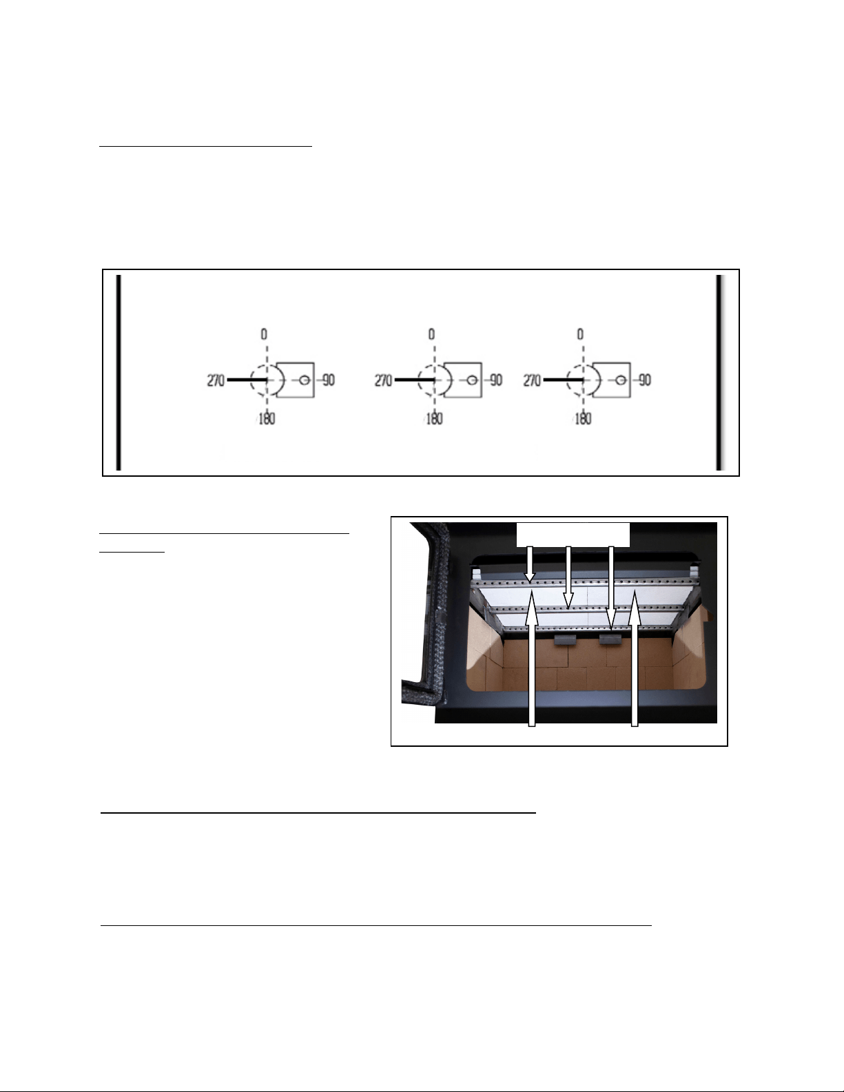
Page | 24
REMPLACEMENTDESCOMPOSANTS
Remplacement dutube debrûleur
La partie supérieure du poêle compte troistubes de brûleur différents. Pour remplacer un
tube,assurez‐vousdecommanderletubequicorrespondàceluiquevousdevezremplacer.Retirez
ensuitelavissituéeducôtégauchedutubeàl’aided’unedouilleoud’unecléàfourchesde5/16po.
Assurez‐vousdeconserverlavis.Poussezletubeversladroite,puisretirez‐le(enramenantletube
verslagaucheaprèsavoirretirécecôtédel’orifice).Pour remplacerletube,inversez laprocédure
indiquéeci‐dessus.Assurez‐vousd’installerlestubesdansl’ordreadéquat.(Del’avantà
l’arrière)
Remplacementdu panneau enfibr esde
céramique
Ilyaquatrepanneauxdefibres
situésenhautdecepoêle,endeuxcouches.
Alorsquelacoucheinférieureestorientée
«Nord/Sud»commeindiqué,lacouche
supérieureestorientée«Est/Ouest».Pour
remplacerunpanneaufissuréoubrisé,
retirezd’abordletubedebrûleur avant.
Retirez
ensuitelepanneauquevousdevez
remplacer.Installezlenouveaupanneau(les
deuxpanneauxdoiventêtreplacés
directementsurlestubesdebordàbord).
Replacezletuberetiréprécédemment.
Remplacementdelaniche(voirladispositiondesbriquesàlapage33)
Pourremplacerlaniche,retirezd’abordlebacàcendres.Retirezensuitelesdeuxécrousde
9/16poquiretiennentles boulonsdecarrosserieenplace.Ouvrezlaporteavantdupoêleetsoulevezla
niche.Installezdenouveauxboulonsdecarrosserieouréinstallezlesboulonsexistantsdanslestroussur
leborddelaniche,etréinstallezlanich einversementàlamanièredontvous l’avezretirée.
Retraitdel’écranthermiqueetdupanneauarrière(pouraccéderauxautrescomposants)
Deuxvisde5/16posetrouventàl’arrièredel’écranthermique.Pourretirerl’écranthermique,
enlevezlesdeuxvisàl’aided’unedouilleoud’unecléàfourchesde5/16po.Tirezensuitel’écran
thermiqueverslehautetrepoussezversl’arrièrelepanneauarrière.
PARTIEAVANTDUPOÊLE
PARTIEARRIÈREDUPOÊLE
270DEGRÉS
270DEGRÉS
270DEGRÉS
TUBESDEBRÛLEUR
PANNEAUX
EN
FIBRES
DE
CÉRAMIQUE
(Bl
anc
)
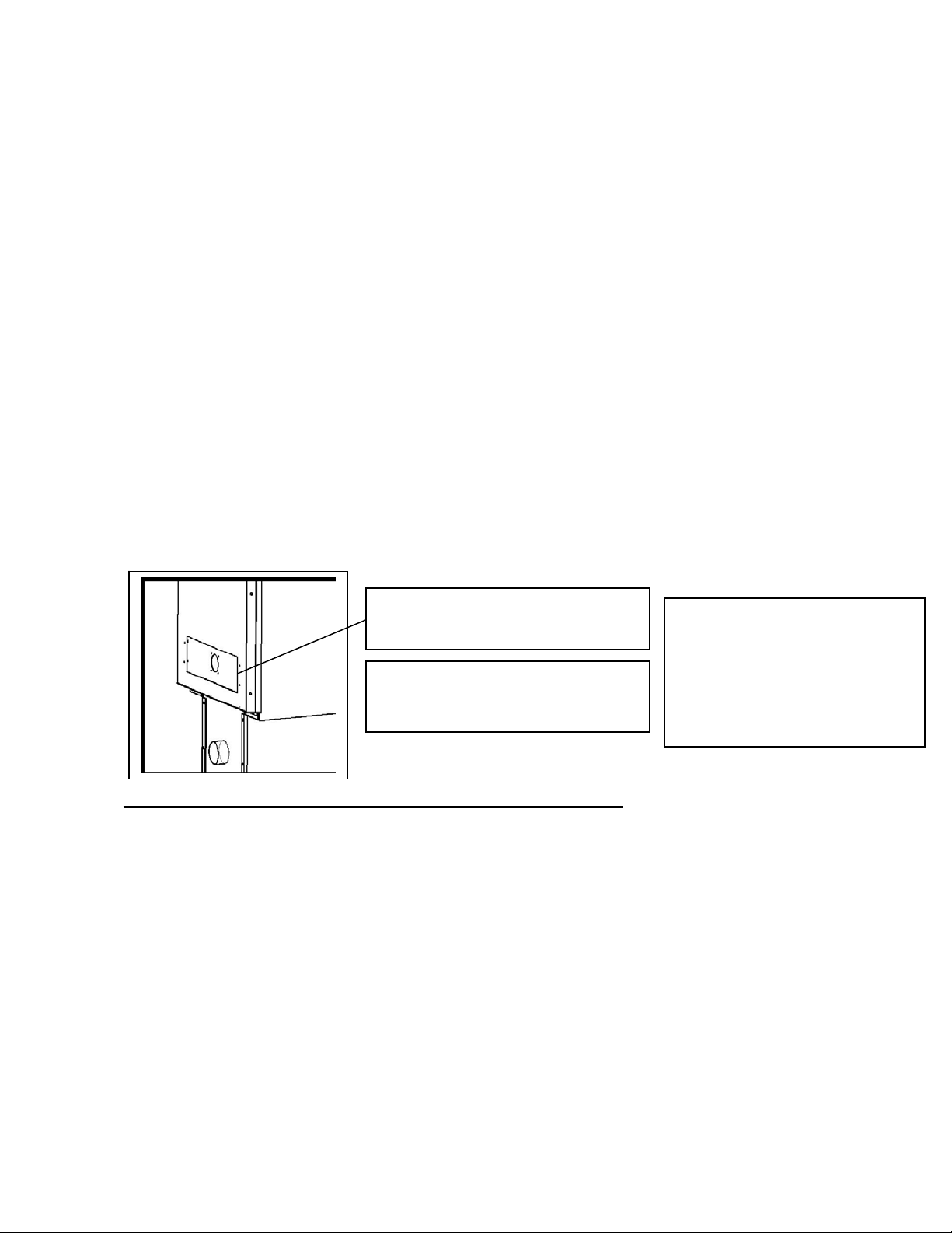
Page | 25
ACCESSOIRESENOPTION
Ventilateur:Lepoêleàboisaaussiétéconçu pour êtreutiliséavecunventilateurdeconvectionpour
assurerunecirculationdechaleursupplémentaire.Lepoêleestmunideprofilésdeconvectionqui
permettentauventilateurdepièced’extrairelachaleurdeszoneslespluschaudesdupoêleetde
la
transférerdanslamaison.Lesvisdemontageduventilateursontinstalléesdans leprofilédeconvection
arrièreàl’usine.Lemontageduventilateurn’exigequ’unedouilleouunecléàfourchesde5/16popour
retirercesvisetinstallerleventilateur.
Fonctionnementetutilisationdesassemblagesélectriques,
ycomprisl'entretienetleroutageducordon
d'alimentation‐
Lorsdel’acheminementducordond’alimentation,prenez soindelegarderàl’écartdeszoneschaudes
del’appareiletn’oubliezpasqueceventilateurnedoitêtreutiliséqu’aveclepoêle.Consultezleschéma
ci‐dessouspourobtenirplusdeprécisions
surl’installationduventilateurdepièce.Voirpages17et18
pourlesinstructionsdefonctionnement.
CetappareilpeututiliserleventilateurAC‐16(offertdesérieavecl’appareil)oulanouvelleversionde
ventilateurAC‐30.Lesdeuxversionssontinstalléesàl’aidedesquatrevisde5/16poposées
àl’usine.
Leventilateurdecirculationdechaleurenoptionsurcepoêlenécessiteungraissagepériodiqueeffectuéaumoins
touslestroismoisenutilisationnormale.Pourgraisserdefaçonappropriéeleventilateur,utilisezuncompte‐
gouttesoculaireouundispositifsimilairepourappliquerde5à7gouttelettesd’huileSAE20
dansl’orificed’huiledu
côtédumoteurduventilateur.
AC-16: 115 V, 60 Hz, .8 Amp
AC-30: 115 V, 50/60 Hz, 2.1/1.7 Amp
Avertissement:Coupezl’alimentation
électriqueduventilateuravant
l’installation.
(4)visautotaraudeuses,têtede5/16po
(préinstalléesdansl’appareil).
L’appareildoitêtredébranché
pendantl’été(etlorsqu’iln’estpas
utilisé),afind’aideràleprotéger
contrelesrisques
d’endommagementcausésparla
foudreetpard’autresperturbations
ducourantélectrique.

Page | 26
RENSEIGNEMENTSSURL’EPA
Lesajoutssuivantsàvotreguided’utilisationvouspermettrontderéduireau
minimumlesémissionsproduitesparvotrepoêleàbois.Desconseilsdesécurité
importantsvoussontégalementprésentés.
‐ Installationadéquate–Veuillezconsulterlasectionsurl’installationdevotreguide
d’utilisationetsuivrelesdirectivesénoncéesafind’assurerlasécuritéetderéduireau
minimumlesémissions.
Renseignementssupplémentaires:
Généralitéssurlaventilation:
Tirage:Letiragedésignelaforcequidéplacel’airdel’appareiljusquedanslacheminée.La
puissance du tirage dans votre cheminée dépend de la longueur de la cheminée, de la
géographie locale, des obstructions à proximité et d’autres facteurs. Un tirage trop élevé
peut entraîner des températurestropélevéesdansl’appareil et endommager la chambre
de combustion catalytique. Un tirage inadéquat peut entraîner un refoulement de fumée
danslapièceetobstruerlacheminéeoulecatalyseur.
Untirageinadéquatentraîneradesfuitesdefuméedanslapièceparlesjointsderaccord
del’appareiletdelacheminée.
Un taux de combustion incontrôlable ou une température trop élevée indique un tirage
excessif.
Soyezconscientdel’emplacementdel’installation:unrefoulementetd’autresproblèmes
dequalitédel’airpeuventsurvenirdanslesvalléesousil’appareilestinstalléàproximité
d’habitationsvoisines.
Cepoêleàboisutiliseunsystèmedetiragenatureldanslequellesystèmedecheminée
tirel’airdanslepoêle.Cetappareildoitêtreinstalléconformémentauxtechniquesde
ventilationdécritesendétailci‐après.Lenon‐respectdesdétailsmentionnéspourraitréduire
sonrendementetcauserdesdommagesmatériels,desblessuresoulamort.Évitezd’avoir
recoursàdesexpédientslorsdel’installationdusystèmedeventilation.England’sStoveWorks
n’estpasresponsabledesdommagescausésparuneinstallationincorrecteounonsécuritaire.
Assurez‐vousdebiensuivretouteslesinstructionsdufabricantrelativesausystèmede
ventilation,surtoutparrapportauxdistancesminimalesnécessairesaveclesmatières
combustibles.Assurez‐vouségalementd’utiliserunécranantirayonnementdegrenierafin
d’éviterquel’isolantentreencontactavecunecheminéequitraverseungrenier.
Lesystèmedecheminéeestle«moteur»dupoêleàbois.Ilestdoncessentielquele
systèmedeventilationsoitinstalléexactementselonladescriptionindiquéedanslasection
suivanteafind’assurerunfonctionnementadéquatdel’appareil.
Pourtoutequestionrelativeàl’installationsécuritairedupoêle,appeleznotreservice
desoutientechniqueau1800245‐6489.Communiquezavecunagentresponsablelocalafinde
vousassurerquel’installationestconformeauxexigencesmunicipalesetnationalesenmatière
depréventiondesincendies.Sivousn’êtespascertaindepouvoirinstallerlepoêledefaçon
sécuritaire,nousvoussuggéronsfortementdefaireappelàuninstallateurlocalcertifiéparle
NFI(NationalFireplaceInstitutedesÉtats‐Unis).
Certifiéconformeauxnormesde2020surl’émissiondeparticuleslorsdel’utilisation
decordwoodparl’ENVIRONMENTALPROTECTIONAGENCYdesÉtats‐Unis.
Page | 27
Consignespourlaventilation:
• InstallezTOUJOURSletuyaudeventilationenrespectantrigoureusementlesinstructions
etlesindicationssurlesdégagementsquiaccompagnentlesystèmedeventilation.
• NERACCORDEZPASLEPOÊLEÀBOISÀUNCONDUITDEFUMÉEDÉJÀUTILISÉPOURUN
AUTREAPPAREIL.
• N’INSTALLEZPASunrégulateurdetirage
niaucunautredisposit if deréglagedanslesystèmed’évacuationparventilationdecetappareil.
• UTILISEZunmanchond’emboîtementmuralhomologuépourtraverserunmuretun
supportdeplafondouuncoupe‐feupourtraverserunplafond.
• INSTALLEZtroisvisàtôlesurchaquejointderaccorddecheminée.
• ÉVITEZ de trop nombreux coudes et parcours horizontaux, car ils réduiront le tirage du
systèmedeventilation,cequinuiraaurendementdupoêle.
• INSPECTEZsouventlesystèmedeventilationafindevousassurerqu’ilnecontientpasde
créosote,decendresvolantesoud’autresobstructions.
• NETTOYEZlesystèmedeventilationcommeilestdécritdanslasectionsurl’entretiendu
présentguide.
• RESPECTEZlarègle10‐3‐2concernantlesraccordementsdelacheminée.
• INSTALLEZleraccorddecheminéeàparoisimpleavecl’extrémitémâleverslebaspour
éviterlesfuitesdecréosote.Suivezlesinstructionsdufabricantderaccordsdecheminéeà
paroidoubleconcernantl’installationadéquatedestuyaux.
AVERTISSEMENT:LessurfacesdusystèmedeventilationdeviennentCHAUDESetpeuvent
causerdesbrûluressivouslestouchez.Ilpeutêtrenécessaired’utiliserunrevêtementoudes
grillesdeprotectionincombustibles.
Règle10‐3‐2:Lesystèmedecheminéedoitseterminerà0,91m(3pi)au‐dessusdupointoùson
axecentraltraverseletoitETlacheminéedoitseterminerà0,61m(2pi)au‐dessusdetoute
partiedulogementdansunrayonde3,05m(10pi)delacheminée.
‐ Fonctionnementetentretien–Consultezlessectionssurlefonctionnement(mode
d’emploi)etl’entretien(ycomprisleretraitetl’éliminationdescendres)devotreguide
d’utilisationetsuivezlesdirectivesénoncéespourassurerlasécuritéetréduireau
minimumlesémissions.
Renseignementssupplémentaires:
Respectezlesinstructionsdevotreguided’utilisationconcernantl’allumaged’unfeuafinde
produireunfeuappropriéetderéduirelesémissionsvisibles.
Plus:
‐ Alimentationencombustibleetréalimentation:Conseilspratiquespourfaireunfeu–
Consultezvotreguided’utilisationpourobtenirdesrenseignementssurl’alimentation
encombustible(etlaréalimentation)ainsiquesurlesprocéduresd’allumagedefeu
(c.‐à‐d.,faireunfeu).
‐ Allumageduhautverslebas:L’EPAreconnaîtl’efficacitédelaméthoded’allumagedu
hautverslebas.Voustrouverezunbontutorielsurcetteméthodeau
http://woodheat.org/top‐down‐steps.html.Pourallumerunfeuduhautverslebas,
assurez‐vousdesuivrelesinstructionsdevotreguided’utilisationetcommuniquez
avecleservicedesoutientechniquesivousavezdesquestions.

Page | 28
‐ Sélectionducombustible:Lorsquevotreappareildechauffageauboisestcorrectement
installé,vousdevrezutiliserunbonboisdechauffagepourallumerunfeuefficace(lebon
boisenquantitésuffisante)ainsiqueconnaîtredebonnesméthodesd’allumagedefeu.
Lesétapespratiquessuivantesvousaiderontàtirerlemeilleurrendementdevotrepoêle
àboisoufoyer.
Laissezvotreboissécheràl’extérieurtoutl’étépendantaumoinssixmoisavantdele
brûler.Unboiscorrectementséchéestplusfoncé,présentedesfissuressurlefil
d’extrémitéetsonnecreuxlorsquevouslecognezcontreunautremorceaudebois.
Conservezvotreboisàl’extérieur,bienempilésurlesolavecuneprotectionau‐dessus.
Nebrûlezqueduboisbiensecquiaétécorrectementfendu.
Pourallumerunfeu,utilisezuniquementdupapierjournaletduboisd’allumage,comme
ilestmentionnéprécédemmentdansleguide.
Faitesdesfeuxchauds.
Pourmainteniruneventilationadéquate,retirezrégulièrementlescendresdevotre
appareildechauffageauboisdansunrécipientenmétaldotéd’uncouverclequevous
conserverezàl’extérieur.
Renseignementssurl’humidimètre
Leboisdechauffagepeutêtrebrûlélorsqu’ilauneteneurenhumiditéde10à25%.
Lesbûchesfraîchementcoupéespeuventavoiruneteneurenhumiditéde80%ouplus,
selonl’essencedubois.Puisqueleboisrétrécit, etpeutégalementsefendre,setordreou
autrementchangerdeformeenséchant,laplupartdesboisdoiventêtreséchésavant
d’êtreutilisés.Leséchageàl’airestlaméthodelaplusfréquemmentutiliséepourlebois
enstéré.DanslaplupartdesrégionsdesÉtats‐Unis,lateneurenhumiditéminimalequ’il
estpossibled’obtenirparunséchageàl’airestd’environ12à15 %.Laplupartdes
matériauxséchésàl’airontuneteneurenhumiditéavoisinant20%lorsqu’ilssontutilisés.
Pourvérifierlateneurenhumiditédevotreboisdechauffage,enfoncezsimplement
lestigesdansleboisetattendezlalecturedel’humidimètre.Souvenez‐vousdene
pasenfoncerlestigesdel’humidimètreuniquementdanslesextrémitésduboisde
chauffage.Pourobtenirunelectureprécise,fendezlabûcheetfaitesletestaucentre.Le
centredelabûchecontiendralaplusforteteneurenhumidité.
Àquelledistancedois‐jeenfoncerlestigesnonisoléesdanslebois?
Jusqu’àuneprofondeurmaximale,sic’estpossible.Toutefois,àdestauxd’humidité
inférieursà10%,ilestgénéralementsuffisantdecréeruncontactfrancaveclebois.
Àdestauxd’humiditésupérieurs,etparticulièrementsil’inclinaisonestgrande,une
pénétrationcomplèteestessentielle.

Page | 29
‐ COMBUSTIBLESÀÉVITER:
MISEENGARDE
N’UTILISEZJAMAISD’ESSENCE,DECOMBUSTIBLEPOURLAMPEAPPARENTÉÀL’ESSENCE,DE
KÉROSÈNE,DELIQUIDED’ALLUMAGEPOURCHARBON,NIAUCUNLIQUIDESIMILAIREPOUR
ALLUMEROURAVIVERUNFEUDANSCETAPPAREILDECHAUFFAGE.CONSERVEZDETELS
LIQUIDESÉLOIGNÉSDEL’APPAREILDECHAUFFAGELORSQUECELUI‐CIFONCTIONNE.DEPLUS,
NEDISPOSEZJAMAISD’ALLUME‐FEUXSURUNESURFACECHAUDENISURDESTISONSDANSLE
POÊLE.N’UTILISEZPASDEPRODUITSCHIMIQUESNIDEFLUIDES
POURALLUMERLEFEU.
NEFAITESPASBRÛLERDELIQUIDESINFLAMMABLESCOMMEDEL’ESSENCE,DUNAPHTA
OUDEL’HUILEPOURMOTEUR.
NEFAITESPASBRÛLERDESDÉCHETS,DUGAZONCOUPÉOUDESRÉSIDUSDEJARDINAGE,DES
MATÉRIAUXCONTENANTDUCAOUTCHOUC,YCOMPRISDESPNEUS,DESMATÉRIAUX
CONTENANTDUPLASTIQUE,DESDÉCHETSDEPRODUITSPÉTROLIERS,DELAPEINTUREOUDU
DILUANTÀPEINTURE,DESPRODUITSBITUMINEUX,DESMATÉRIAUXCONTENANTDE
L’AMIANTE,DESDÉBLAISOU DESDÉBRISDECONSTRUCTION,DESTRAVERSESDECHEMINDE
FEROUDUBOISTRAITÉSOUSPRESSION,DUFUMIEROUDESRESTESD’ANIMAUX,DUBOISDE
GRÈVEIMPRÉGNÉD’EAUSALÉEOUDESMATÉRIAUXPRÉALABLEMENTSATURÉSENEAUSALÉE,
DESPRODUITSDEPAPIER,DUCARTON,DUCONTREPLAQUÉOUDESPANNEAUXDE
PARTICULES.L’INTERDICTIONDEBRÛLERCESMATÉRIAUXNEVOUSEMPÊCHEPASD’UTILISER
DESALLUME‐FEUÀBASEDEPAPIER,DECARTON,DESCIURE,DECIREOUD’AUTRES
SUBSTANCESSEMBLABLESPOURALLUMERUNFEUDANSLEPOÊLEÀBOIS.LACOMBUSTION
DECESMATÉRIAUXPEUTCOMPROMETTREL’EFFICACITÉDUPOÊLEETPRODU IREDELAFUMÉE
ETDESVAPEURSTOXIQUES.
‐ Pratiquesdechauffageauboissécuritaires
Unefoisquevotreappareildechauffageauboisestcorrectementinstallé,suivezcesdirectivespour
assurerunfonctionnementsécuritaire:
Conserveztouslesarticlesdemaisoninflammables(draps,meubles,journauxetlivres)loinde
l’appareil.
Pourallumerunfeu,utilisezuniquementdupapierjournal,duboisd’allumageetunallume‐feu
entièrementnatureloubiologique.N’utilisezjamaisd’essence,dekérosèneoud’allumoirà
charbonpourallumerunfeu.
Nebrûlezpasdebûcheshumidesouvertes(nonséchées).
N’utilisezpasdebûchesfaitesdecireoudesciuredeboisdansvotrepoêleàbois,carellessont
conçuespourdesfoyersouverts.Sivousutilisezdesbûchesfabriquées,prenezcellesquisont
faitesdesciuredeboiscompresséeà100%.
Faitesdesfeuxchauds.Pourlaplupartdesappareilsdechauffage aubois,unfeuquicouven’est
nisécuritaireniefficace.
Gardezferméeslesportesdevotreappareildechauffageauboissaufpourajouterdesbûchesou
alimenterlefeu.Desproduitschimiquesnocifs,commelemonoxydedecarbone,peuventêtre
libérésdansvotredomicile.
Retirezrégulièrementlescendresdevotreappareildechauffageauboisdansunrécipienten
métaldotéd’uncouvercle.Rangezlerécipientcontenantlescendresàl’extérieur,surunedalle
decimentoudebrique(etnonpassuruneterrasseenboisniàproximitédebois).Consultezles
instructionssurleretraitdescendresdansleguided’utilisation.
Gardezunextincteurd’incendieàportéedelamain.
N’oubliezpasdeconsulterlesprévisionslocalessurlaqualitédel’airavantd’utiliservot repoêleàbois.

Page | 30
‐ Commanded’air:CONSULTEZVOTREGUIDED’UTILISATIONpourobtenirplusde
renseignementssurl’utilisationappropriéedelacommanded’air(danslasection
Fonctionnement).
‐ RETRAITDESCENDRES–Suivezlesinstructionsduguided’utilisationconcernantleretrait
etl’éliminationdescendres.
‐ REMPLACEMENTdespiècesessentiellesàuntauxd’émissionfaible–Suivezles
instructionsduguided’utilisationconcernantleremplacementdesjointsetdesautres
piècesessentiellesàuntauxd’émissionfaible.
Rappel:«Afind’assurerlebonfonctionnementdupoêleàbois,vousdevezl’inspecteretle
réparerpériodiquement.Envertudesrèglementsfédéraux,ilestinterditd’utilisercepoêleà
boisd’unemanièrenonconformeaumoded’emploiindiquédansleprésentguide.»
Plus:Tubesdebrûleur–Pourremplaceruntube,assurez‐vousdecommanderletubequi
correspondàceluiquevousdevezremplacer.Retirezensuitelavissituéeducôtégauchedu
tubeàl’aided’unedouilleoud’unecléàfourchesde5/16po.Assurez‐vousdeconserverlavis.
Poussezletubeversladroite,puisretirez‐le(enramenantletubeverslagaucheaprèsavoir
retirécecôtédel’orifice).Pourremplacerletube,inversezlaprocédureindiquéeci‐dessus.
Assurez‐vousd’installerlestubesdansl’ordreadéquat.(Avantversl’arrière)
‐ Détecteursdefumée
England’sStoveWorks,Inc.recommandefortementl’utilisationdedétecteursdefuméedans
chaquepiècedelamaison.Cependant,lefaitdeposerundétecteurdefuméedirectement
au‐dessusdel’appareilpourraitcauserdesalarmesintempestives.
MISEENGARDE
Cetappareilestconçupourfonctionneruniquementlorsquelaporteestfermée.L’utilisation
dupoêleaveclaporteouverteprovoqueraitunrefoulementdefuméeetunecombustion
lenteetinefficace.
Deplus,l’utilisationdecombustiblesinterditspeutêtredangereuseetproduireunexcèsde
monoxydedecarbone.Lemonoxydedecarboneestungazmortelquiestinodoreetincolore.
Ilestfortementrecommandéd’utiliserundétecteurdemonoxydedecarbone.
‐ Conformité:Certifiéconformeauxnormesde2020surl’émissiondeparticuleslorsde
l’utilisationdecordwoodparl’ENVIRONMENTALPROTECTIONAGENCYdesÉtats‐Unis.
‐ Avertissementrelatifauxmodifications:«Cepoêleàboisestdotéd’untaux de
combustionbasminimumrégléenusinequinedoitpasêtremodifié.Envertudes
règlementsfédéraux,ilestinterditdemodifierceréglageetd’utilisercepoêleàbois
d’unemanièrenonconformeaumoded’emploiindiquédansleprésentguide.»
‐ Garantie:Consultezvotreguided’utilisationpourobtenirleformulaired’enregistrement
delagarantieetconnaîtrelesinstructionsrelativesauxprocéduresdelagarantie.Dansle
casdespièces,lesprocéduresderemplacementautitredelagarantiesetrouventsurle
sitedenotremagasindepièces:www.heatredefined.com

Page | 31
DÉPANNAGE
Problème Cause Solutions
Lepoêleémetdelafumée
danslapièce.
1.Tiragefaible 1.1Assurez‐vousquelalongueurdelacheminée
estsuffisantepourrespecterlarègle10‐3‐2.
1.2Augmentezlahauteurdelacheminée.
2.Pressionnégative
danslelogement
2.1Ajoutezunraccordementd’aircomburant
extérieuràl’appareil.
Lefeuestdifficileàdémarrer. 3.Tiragefaible 3.1Assurez‐vousquelalongueurdelacheminée
estsuffisantepourrespecterlarègle10‐3‐2.
3.2Augmentezlahauteurdusystèmedecheminée.
4.Cheminéefroide 4.1Chauffezlabuseenpremierenbrûlantdupapier
journalchiffonnédanslepoêle.
4.2Installezunechasseisoléeautourdescheminées
extérieures.
5.Contre‐tiragedans
lacheminée
5.1Assurez‐vousquelalongueurdelacheminéeest
suffisantepourrespecterlarègle10‐3‐2.
5.2Essayezdechaufferlabuseavecunséchoir
àcheveuxpourcorrigerletirage.
Lavitreestsale. 6.Boishumideouvert 6.1Brûlezseulementduboisquiaséchéaumoins
unanetquiestsec,exemptdeglaceetdeneige.
7.Utilisationdupoêle
àuntauxde
combustionbas
7.1Faitesfonctionnerlepoêleàuntauxde
combustionplusélevéafindepermettreausystème
autonettoyantdemaintenirlavitrepropre.
8.Leboischargéest
tropprèsdelavitre.
8.1Nechargezjamaisleboisdesortequ’iltouche
àlafenêtreenvitrocéramique.
Accumulationdebraisesdans
lachambredecombustion
9.Utilisationdupoêle
àuntauxde
combustionélevé
9.1Réduisezl’admissiond’aircomburantet
permettezauxbraisesdebrûleravantderajouter
dubois.
Lefeuesthorscontrôle. 10.Tirageexcessif 10.1Réduisezlahauteurdelacheminée.
11.Fuited’air 11.1Inspectezlesjointsd’étanchéitédelafenêtre
etdelaporteetremplacez‐lesaubesoin.
12.Boisdechauffage
tropsec
12.1Brûlezseulementduboisenstérésec.
Nefaitespasbrûlerduboisséchéauséchoirou
duboisàpalettes.
Lacheminéedégageune
fuméeexcessive.
13.Utilisationdupoêle
àuntauxde
combustionbas
13.1Faitesfonctionnerlepoêleàuntauxde
combustionplusélevépouractiverlacombustion
secondaire.
14.Boishumideouvert 14.1Brûlezseulementduboisquiaséchéaumoins
unanetquiestsec,exemptdeglaceetdeneige.
15.Nouvellecharge
deboisquine
s’enflammepas
15.1Faitescarboniserlanouvellechargedebois
jusqu’àcequ’elles’enflammecomplètementetque
lacombustionsecondaireactiveseproduisedansla
chambredecombustion.

Page | 32
LISTE DES PIÈCES DE RECHANGE
Description
N°depièce
Par
appareil
Écranthermiquearrière(BOULONNÉ) AC‐W02HS 1
Panneauarrière(BOULONNÉ) AC‐W02RP 1
Tourmalin AC‐ADW01 1
Porte CA‐W02 1
Écransthermiqueslatéraux AC‐W01SHS
2
Grandventilateurnouvelleversion(enoption) AC‐30 1
Petitventilateurdesérie AC‐16 1
Troussedejointd’étanchéitédevitre,
plat,3/4po
AC‐GGK 1
Troussedejointd’étanchéitédeporte,
hautedensité,3/4po
AC‐DGKHD 1
Tubedebrûleuravant AC‐W06FBT 1
Tubedebrûleurcentral AC‐W02MBT 1
Tubedebrûleurarrière AC‐W02RBT 1
Vitred’unedimensionde52,71x32,07cm
(20,75x12,625po)
AC‐G51 1
Panneauenfibresdecéramique AC‐W02CFB 4
Petitepoignéeàressort(nickeletlaiton) AC‐SH4N/AC‐SH4 1
Grossepoignéeàressort(nickeletlaiton) AC‐SHN/AC‐SH 1
Couverclearrièreduventilateur AC‐BBC30 1
Languettesdevitre AC‐W01GT 4
Axesdecharnière AC‐HP 2
Ensemblederaccordàl’airextérieur AC‐OAK3
1
Nicheàtroud’air AC‐DB02
1
*POUR CONNAÎTRE LA DISPOSITION DES BRIQUES ET
LES NUMÉROS DE PIÈCE, CONSULTEZ LA PAGE 33*
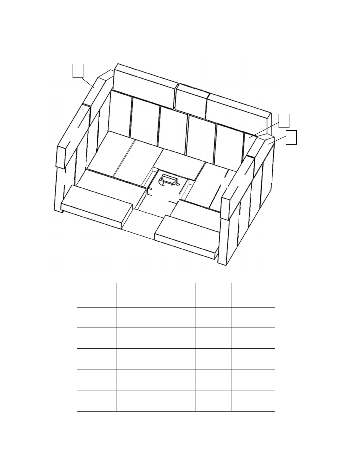
Page | 33
DISPOSITION ET REMPLACEMENT DES BRIQUES
REMARQUE:Lesbriquessurlescôtésetàl’arrièredevrontêtreinstalléesaprèslalivraison
NUMÉRO
DESCHÉMA
DIMENSIONSDES
BRIQUES
NUMÉRO
DEPIÈCE
QUANTITÉ
PARPOÊLE
1 22,86x10,16x3,18cm
(9x4x1,25po)
AC‐SB
26
2 10,8x10,16x3,18cm
(4,25x4x1,25po)
AC‐SB4.25
1
3 20,32x10,16x3,18cm(8x4
x1,25po)avecl’encoche
AC‐SB8x4
2
4 16,51x10,16x3,18cm
(6,5x4x1,25po)
AC‐SB6.5
1
BOUCHONDETRAPPE
ÀCENDRES
CA‐30ADP
1
1
2
3
4
3
Niche
Acier
1
1
1
1
1
1 1
1
1
1
1
1
1
1
1
1
1
1
1
1
1
1
1
1
1
Bouchon
decendre
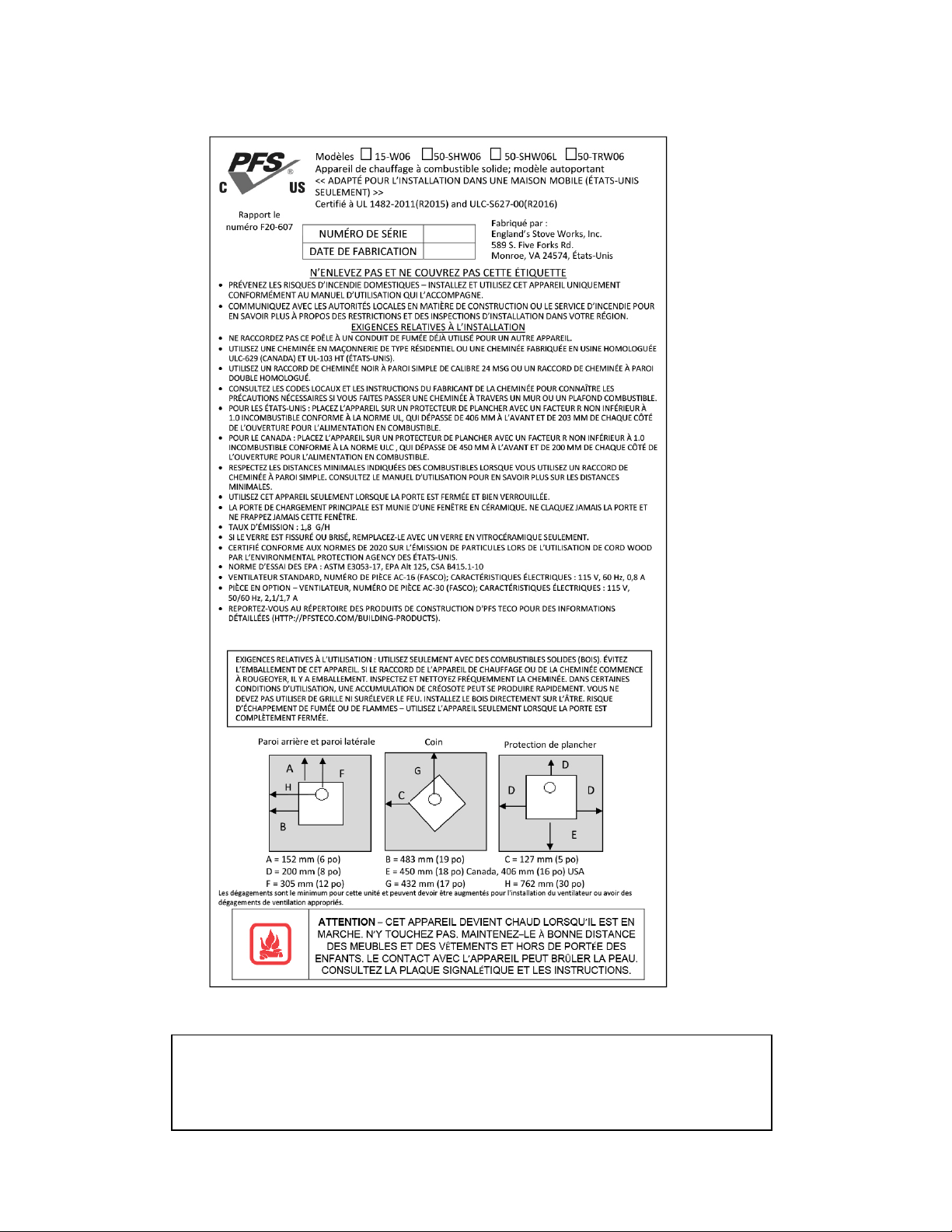
Page | 34
Vous pouvez inscrire la date de fabrication et le numéro de série de votre appareil
dans les espaces prévus à cet effet sur cette étiquette, pour référence ultérieure.
Cette étiquette comprend également des renseignements de sécurité, comme la
norme d’essai UL (ULC au Canada), à l’intention de vos représentants locaux ou
de toute autre personne qui peut en avoir besoin.

GARANTIE LIMITÉEDE CINQ (5) ANS
Àpartirdeladated’achatparlepropriétaired’origine
Lagarantielimitéedufabricantcouvrelesélémentsci‐dessous:
Cinq ans:
1. Lesjointsd’acieraucarboneetlesjointssoudésdufoyersontgarantis
pendantcinq(5)anscontrelafissuration.
2. Laporteetlescharnièresenfontesontgarantiespendantcinq(5)anscontre
lefendillement.
Un an:
1. Lescomposantsélectriques,lesaccessoires,leverreetlasurfacepeintedu
poêlesontgarantispendantun(1)anàpartirdeladated’achat.
Conditions et exclusions
1. Lesdommagescausésparunesurchauffeannulentvotregarantie.
2. Cettegarantienes’appliquepassilesdommagessontcausésparunaccident,
unemanipulationinappropriée,uneinstallationinadéquate,uneutilisation
incorrecte,unusageabusif,uneréparationnonautoriséeouunetentativede
réparationnonautorisée.
3. Lefabricant n’est
pasresponsabledesdommagesindirects,accessoiresou
consécutifsdécoulantduproduit,ycomprislescoûtsoudépenses,oula
réparationpendantlespériodesdemauvaisfonctionnementoudenon‐utilisation
duproduit.*N'utilisezPASdematériauxoudecomposantsderemplacementpour
remplacerl'équipementd'origine.
4. Lefabricantdéclineratoute
responsabilitépourlesdommagesconsécutifsen
casdeviolationdetoutegarantieécriteouimplicite.
5. Cettegarantienecouvrepasl’usuredespiècesinternesdusystèmede
combustion,ycomprislesjointsd’étanchéité.
6.Lagarantieestnullesil'unitéestpasutiliséconformémentaumanueldu
propriétaire.
**CertainsÉtatsoucertainesprovincesnepermettentpasl’exclusionoulalimitationdesdommagesaccessoiresouconsécutifs,desorte
quelesexclusionsmentionnéesci‐dessuspeuventnepass’appliqueràvous.**
Procédure
L’acheteurdoitsoumettreuneréclamationpourdéfautpendantlapériodede
garantieetpayerletransportverslecentredeserviceetàpartirducentredeservice
désignéparlefabricant.Lerevendeurquiavendul’appareiloulefabricant,ànotre
gré,effectueralaréparationsousgarantie.
Autres droits
Cettegarantievousconfèredesdroi tsprécis.Ilestpossiblequevous disposiez
égalementd’autresdroits,quivarientd’unÉtatoud’uneprovinceàl’autre.
Veuillez noter : Cette garantie est nulle et non avenue si l’acheteur n’envoie pas
la carte d’enregistrement de la garantie ci-jointe ET une copie du reçu de vente
dans les trente (30) jours, à compter de la date d’achat.
Danslecasdespièces,lesprocéduresderemplacementautitredelagarantiese
trouventsurlesitedenotremagasindepièces:www.heatredefined.com

Page |36
Avis important
Pour que la présente garantie soit valide, nous DEVONS recevoir et conserver dans
nos dossiers cette information relative à l’enregistrement. Veuillez nous envoyer
cette information dans les trente (30) jours suivant la date d’achat originale.
Il y a trois moyens faciles de nous faire parvenir cette information.
Adresse postale
England’s Stove Works, Inc.
Technical Support Department
P.O. Box 206
Monroe, Virginia 24574,
États-Unis
Télécopieur
1 434 929-4810 – 24 heures par jour.
Enregistrement en ligne
Consultez notre page d’enregistrement de la garantie sur notre site Web à :
www.heatredefined.com
Les pieces – www.heatredefined.com
(LA CARTE DE GARANTIE SE TROUVE À LA PAGE SUIVANTE.)

ENREGISTREMENTDELAGARANTIEsurlesproduitsEngland’sStoveWorks®
Renseignements sur l’acheteur
I. Nom de l’acheteur
II. Adresse
III. Ville_______________________Province________Code postal
IV. Numéro de téléphone :
V. Courriel
Renseignements sur le détaillant
VI. Nom du détaillant
VII. Adresse
VIII. Ville_______________________ Province________ Code postal__________
Renseignements sur l’appareil
IX. Numéro de modèle
Date d’achat
X. Prix d’achat
XI. Numéro de série
Date de fabrication
Questions relatives à l’achat
Comment avez-vous entendu parler de notre produit? (Veuillez cocher l’une des
réponses suivantes.)
De bouche à oreille Démonstration Internet
Autre :
À quel endroit vous a-t-on donné des renseignements sur notre produit?
Au téléphone Chez un détaillant (nom du détaillant) Internet
Autre :