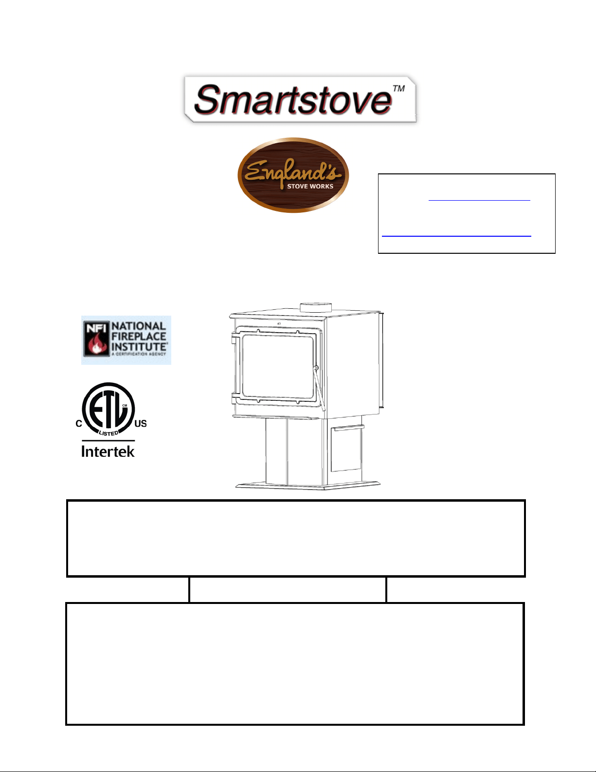
THE
MADISON
15‐SSW01,50‐SHSSW01,
50‐TRSSW01
INSTALLATION&OPERATION
MANUAL
Manufactured
By:
England’sStoveWorks,
Inc.
POBox
206
Monroe,VA
24574
www.heatredefined.com
(800)245‐6489
Rev.4/2020
CAUTION
Pleasereadthisentiremanualbeforeinstallationanduseofthiswood
fuel‐
burningappliance. Keepchildren,furniture,fixturesandallcombustibles
away
fromanyheating
appliance.
SAVETHESEINSTRUCTIONS
SAFETY
NOTICE
Failuretofollowtheseinstructionscanresultinpropertydamage,bodily
injury
orevendeath. Foryoursafetyandprotection,followthe
installatio n
instructionsoutlinedinthismanual. Contactyourlocalbuildingorfire
officials
aboutrestrictionsandinstallationinspectionrequirements(including
permit s)
inyour
area.
Page | 2
IMPORTANT:IFYOUHAVE APROBLEMWITHTHISUNIT,DO
NOTRETURNITTOTHEDEALER. CONTACTTECHNICAL
SUPPORT@1‐800‐245‐6489
MobileHomeUse(ApprovedforUSAonly):
Thisfreestandingwoodunitisapprovedformobilehomeor
doublewideinstallationwiththeoutsidecombustionairhook‐
up. Seethe“Installation”sectionofthismanualfordetails
pertainingtomobilehomeinstallations. Mobilehome
installationmustbeinaccordancewiththeManufactured
HomeandSafetyStandard(HUD),CFR3280,Part24.
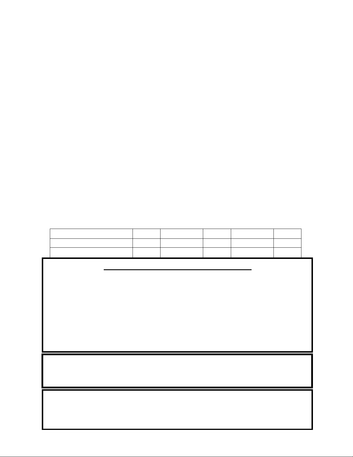
Retainforyour
files
Model
Number
Date
of
Purchase
Date
ofManufacture
Serial
Number
*Thisinformationcanbefoundonthesafetytagattachedtotherearoftheunit.
Havethisinformationon handifyouphonethefactoryoryourdealerregardingthis
product.
•
Keepchildrenaway.
CAUTION
•
Supervisechildreninthesameroomasthisappliance.
•
Alertchildrenandadultstothehazardsofhightemperatures.
•
DoNOToperatewithprotectivebarriersopenorremoved.
•
Hotwhileinoperation!Keepclothing,furniture,draperiesandother
combustiblesaway. Contactmaycauseskinburns!
•
InstallationMUSTcomplywithlocal,regional,stateandnationalcodesand
regulations.
•
Consultlocalbuilding,fireofficialsorauthoritieshavingjurisdictionabout
restrictions,installationinspection,andpermits.
Page | 3
WELCOME!
Introduction
•
ThankYou!…...............................4
Specifications
•
HeatingSpecifications..................5
•
Dimensions...................................5
•
EPACompliance...........................5
Installation
•
Installation
Overview
...................6
•
ClearancestoCombustibles.........7
•
VentingIntroduction....................8
•
VentingGuidelines.......................8
•
AdditionalVenting
Informatio n
...9
•
Wall
Pass
‐Throughs....................10
•
ApprovedVentingMethods
o ThroughtheWall...........11
o ThroughtheCeiling........12
o MasonryChimney...........13
o MasonryFireplace..........14
•
MobileHomeInstallation...........15
•
OutsideAir
Hook‐Up
...................15
•
FloorProtection.........................16
Operation
•
Break‐InFires.............................17
•
ContinuousOperation...........17‐18
•
Safety
Notes
...............................19
Maintenance
•
StoveMaintenance....................21
•
Inspecting
Gaskets
......................22
•
Finish..........................................22
Replacing Components
•
Glass...........................................23
•
BurnerTubes..............................24
•
CeramicFiberboards...................24
•
DoorHinges................................24
•
HeatShield&BackPanel...........24
•
OtherComponents.....................25
Optional Accessories
•
AC‐16/AC‐30
Blower
..................25
•
SideHeatShield
……...................25
Troubleshooting Guide
•
Troubleshooting.........................26
Illustrated Parts Detail
•
PartsList.....................................27
•
ExplodedPartsDiagram.............28
•
BrickLayout................................29
Warranty
•
SampleTag..................................30
•
Warranty
Details
........................31
•
ImportantNo
tice
........................32
•
WarrantyregistrationForm.......33
*EPAAddendumfollowsWarrantySection
NOTE:CLEARANCESMAYONLYBEREDUCEDBYMEANSAPPROVEDBYTHEREGULATORYAUTHORITY
HAVINGJURISDICTION
DONOTCONNECTTOANYAIRDISTRIBUTIONDUCTORSYSTEM.
DONOTBURNGARBAGEORFLAMMABLEFLUIDSSUCHASGASOLINE,NAPHTHAOR
ENGINEOIL.
DONOTUSECHEMICALSORFLUIDSTOSTARTTHEFIRE.

Page | 4
Thank you for purchasing this fine product from England’s Stove
Works!
England's Stove Works was started, and is still owned by, a family that
believes strongly in a "Do It Yourself" spirit – that’s one reason you
found this product at your favorite “Do It Yourself” store.
We intentionally design and build our stoves so that any homeowner
can maintain his or her unit with basic tools, and we're always more
than happy to show you how to do the job as easily and as
inexpensively as possible.
From our free, downloadable service sheets to our "wizard-style," click-
through Troubleshooting guide on our web site, we have always tried to
help our customers stay "heat-ready," especially when oil and
electricity prices continue to skyrocket.
Please look at our vast Help section on our web site and call our
Technical Support department at (800) 245-6489 if you need any help
with your unit. We are nearly always able to help “walk you through”
any repairs, problems or questions you may have.
PLEASE NOTE: While information obtained on our web site and
through our 800 number is always free of charge, there will be a service
charge incurred with any “on-site” repairs or maintenance that we may
arrange.
Wishing you years of efficient, quality and “comfy” heating,
England’s Stove Works
Technical Support Department
www.HeatRedefined.com
(800) 245-6489
This manual is available for free download on the manufacturer’s web site. It is a copyrighted document and resale
is strictly prohibited. The manufacturer may update this manual occasionally and cannot be responsible for
problems including injuries or damages resulting from the use of information found in any manual from
unauthorized sources.
PLEASE NOTE: If you purchased this model from certain stores, their model number may end in “L” “LC” “H”
“CT”
,
etc. This manual does a
pp
l
y
to those models as well.
CAUTION:Stoveisheavy.
Inaddition,whenhandlinganysheetmetalproducts,beawarethattheremaybesharpedgesorburrs.
Althoughwemakeeveryefforttoeliminateanysharpedges,pleaseusecautionwhenhandlinganymetalparts.
Remembertodisconnect(unplug)thestovefromthepowersourceand
allowittocompletelycooldown
before
p
erformin
g
an
y
maintenance.
Page | 5
SPECIFICATIONS
Heating Specifications
•
MaximumBurnTime**
.................................................................................
6‐8hours
•
ApproximateSquareFootageHeated***
....................................................
2000sq.ft.
•
Firebox
Capacity............ ................................................................................35
pounds
•
FlueCollar
..................................................................................................
6.0in.round
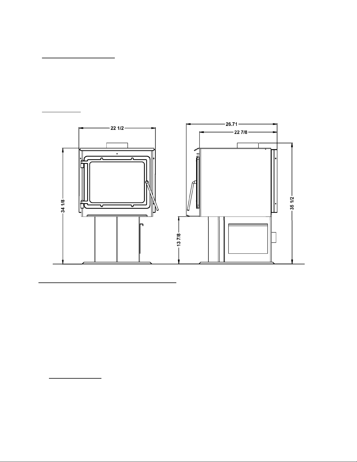
Dimensions(Inches)
EPAandSafetyComplianceSpecifications
EPAComplianceStatus……....... Certifiedtocomplywith2020particulateemission
standardsusingcribwoodfuel.
U.S.TestStandard:USEPA40CFRPart60,Subpart60.536
ParticulateEmissions ……………………………1.956grams/hr
COEmissions……………………………………….1.659grams/min
HeatOutputRange……………………………..11,129–24,369Btu/hr
Efficiency……………………………………………73.77%(HHV)
TestedToEPATestMethod28A,ASTME2780,ASTME2515,ULC/ORD‐C1482&ULCS627‐
00
Notesforthisunit:Productmayvaryslightlyfromdiagram.Clearancesaretheminimumfor
thisunitandmayneedtobeincreasedinthereartohaveproperventclearances.Followall
ventingmanufacturerclearancesandlocalcodes.
***‐Themaximumheatingcapacityofthisunitcanvarygreatlybasedonclimate,constructionstyle,insulationandamyriadofotherfactors.
UsethisinformationinconjunctionwithaBTUlosscalculationforyourhometodetermineifthisunitwillbesufficientforyourneeds.

Page | 6
INSTALLATION
Installation Overview
Whenchoosingalocationforyournewstove,thereareamultitudeoffactorsthat
shouldbetakenintoaccountbeforebeginningtheinstallation.
1.TrafficPatterns–Tohelppreventaccidents,thestoveshouldbeplacedinalocation
whereitisoutofthewayofnormaltravelthroughthehome.
2.HeatFlow–Whendecidingonalocationforthestove,considerthewayheatmoves
throughoutyourhome.Installthestovewhereyouneedthe heat;basement
installationsoftendonotallowsufficientheattoflowtotheupperfloorsandatop
floorinstallationwillnotallowanyheattoreachthefloorsbelow. Alwaysconsider
thatheatrisesandwilltakethepathofleastresistancewhileitisstillhot.
3.ExhaustLocation–Theenginewhichdrivesawoodstoveisthechimneysystem,so
itisimportanttoconsiderpreciselyhowthechimneysystemwillbeintegratedinto
thestoveinstallation. Ideally,awoodstovechimneywillruncompletelyvertical
fromthefluecollaroftheunitallthewaytotheterminationpointabovetheroof
line. Keepingtheentirechimneysysteminsidetheheatedenvelopeofthehome
willensureastrong,easytoinitiatedraftinthechimney. Althoughexteriorchimney
systemsoftenfunctionproperly,theyaremorelikelytosufferfromcolddowndrafts
atstartuporprovideweakdrafttotheunit. Also,considerthecross‐sectionalarea
ofthechimney;althoughexistingmasonrychimneyscanoftenbeused,alarge
externalmasonrychimneywillresultinaunitthatisdifficultorimpossibleto
operateproperly. Inthatcase,aninsulatedchimneylinerwilloftenberequiredto
supplythenecessarydraft.
4.WallConstruction–Locatingthestovesothattheexhaustsystemcanpassbetween
studswillsimplifytheinstallationandeliminatetheneedtoreframeanysectionsof
thewallorceilingtoaccommodatethewallthimbleorceilingbox.
WARNING
•
Donotstoreorusegasolineorotherflammablevaporsandliquidsinthe
vicinityofthisoranyotherappliance.
•
DoNotOver‐fire–Ifanyexternalpartstartstoglow,youareover‐firing.
Reduceintakeairsupply. Over‐firingwillvoidyourwarranty.
•
Complywithallminimumclearancestocombustiblesasspecified.
Failuretocomplymayresultinahousefire.
•
Testedandapprovedforcordwoodonly. Burninganyotherfuelwill
voidyourwarranty.
Page | 7
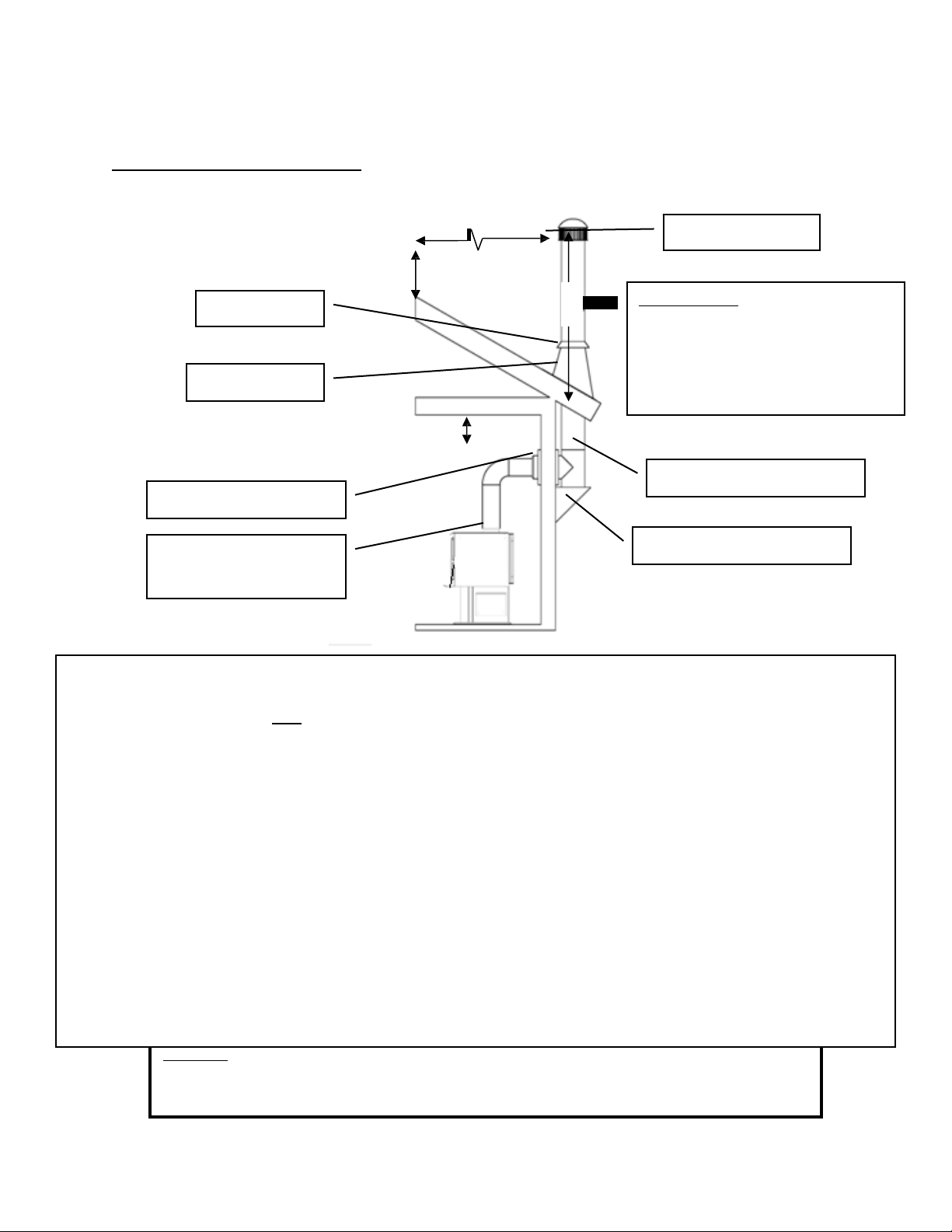
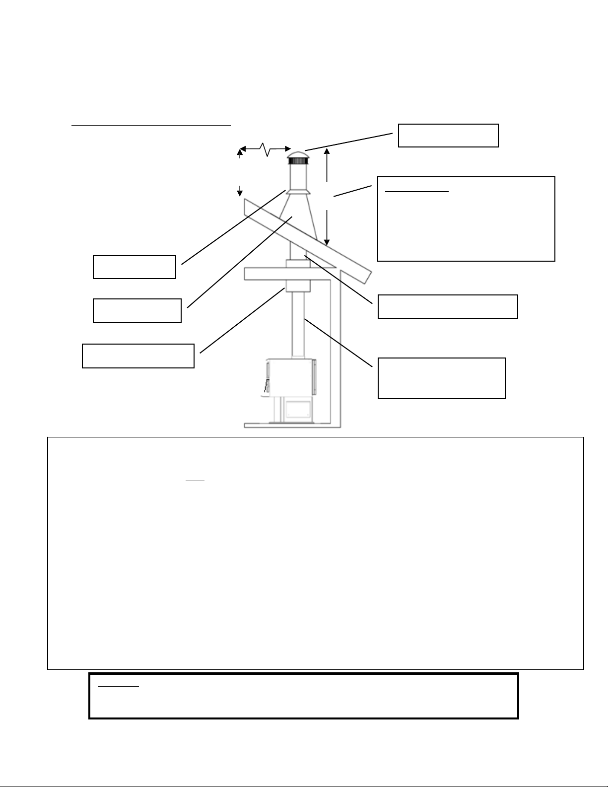
INSTALLATION
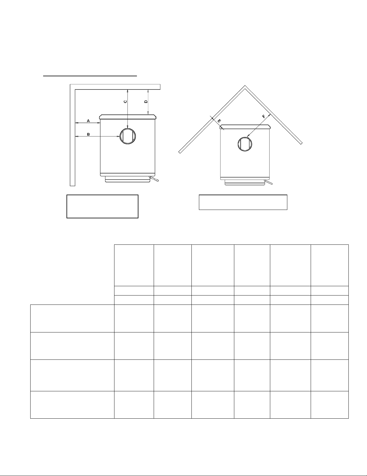
Clearances to Combustibles
Parallel
Wall
Installation
CornerInstallation
WARNING‐INSTALLVENTATCLEARANCESSPECIFIEDBYTHEVENTMANUFACTURER
Unitto
Side
Wall
*
Chimney
Connector
to
Side
Wall
Chimney
Connector
to
Rear
Wall
Unit
to
Rear
Wall
Unitto
Corner
Chimney
Connector
to
Corner
A
B
C
D
E
F
in.(mm.) in.(mm.) in.(mm.) in.(mm.) in.(mm.) in.(mm.)
SingleWall
Chimney
Connector
Unprotected
Surface
21.5
(546.1)
29
(736.6)
12
(304.8)
7.5
(190.5)
9.5
(241.3)
19
(482.6)
DoubleWall
Chimney
Connector
Unprotected
Surface
N/A
N/A
N/A
N/A
N/A
N/A
SingleWall
Chimney
Connector
Unprotected
Surfacewithside
shields.
17.5
(445.5)
25
(635)
12
(304.8)
7.5
(190.5)
5.5
(139.7)
15
(381)
DoubleWall
Chimney
Connector
Unprotected
Surfacewithside
shields.
N/A
N/A
N/A
N/A
N/A
N/A

Page | 8
Venting Introduction
INSTALLATION
Venting Guidelines
Thiswoodstoveoperatesona
naturaldraftsystem,inwhichthechimney
systempullsairthroughthestove. Thisunit
mustbeinstalledinaccordancewiththe
followingdetaileddescriptionsofventing
techniques;notinstallingthestovein
accordancewiththedetailslistedherecan
resultinpoorstoveperformance,property
damage,bodilyinjuryordeath. Avoid
make‐shiftcompromiseswheninstallingthe
ventingsystem. England’sStoveWorksis
notresponsibleforanydamageincurred
duetoapoororunsafeinstallation.
Becertainthatallaspectsofthe
ventingsystemareinstalledtotheventing
manufacturer’sinstructions,particularlythe
requiredclearancestocombustibles. Also,
becertaintouseanatticradiationshieldto
preventinsulationfromcontactinga
chimneywhichpassesthroughanattic.
Thechimneysystemisthe“engine”
whichdrivesawoodstove,soitis
imperativeforproperunitfunctionthatthe
ventingsystembeinstalledexactlyas
describedinthefollowingsection.
Ifquestionsarisepertainingtothe
safeinstallationofthestove,ourTechnical
Supportline(800‐245‐6489)isavailable.
Contactyourlocalcodeofficialtobecertain
yourinstallationmeetslocalandnational
firecodes,andifyou’reuncertainabout
howtosafelyinstall thestove,westrongly
recommendcontactingalocal NFIcertified
installertoperformtheinstallation.
•
ALWAYSinstallventpipeinstrict
adherencetotheinstructionsand
clearancesincludedwithyour
ventingsystem.
•
DONOTconnectthiswoodstoveto
achimneyfluewhichalsoserves
anotherappliance.
•
DONOTinstallafluepipedamper
oranyotherrestrictivedeviceinthe
exhaustventingsystemofthisunit.
•
USEanapprovedwallthimblewhen
passingthroughawallandaceiling
support/firestopwhenpassing
throughaceiling.
•
INSTALLthreesheetmetalscrewsat
everychimneyconnectorjoint.
•
AVOIDexcessivehorizontalrunsand
elbows,asbothwillreducethedraft
of the venting systemand will result
inpoorstoveperformance.
•
INSPECTyour ventingsystemoften,
tobecertainitisclearofcreosote,
fly‐ashandotherrestrictions.
•
CLEANtheventingsystemas
detailedinthemaintenancesection
ofthismanual.
•
ADHEREtothe10‐3‐2ruleregarding
chimneyterminations.
•
INSTALLsinglewallchimney
connectorwiththemaleenddown
topreventcreosoteleakage. Follow
doublewallchimneyconnector
manufacturer’sinstructions
regardingproperpipeinstallation.
WARNING:VentingsystemsurfacesgetHOT,andcancauseburnsif
touched. Noncombustibleshieldingorguardsmayberequired.
Page | 9
FlueGasDirection
Additional Venting Information
INSTALLATION
•
Donotmixandmatchcomponentsfromdifferentpipemanufacturerswhenassembling
yourventingsystem(i.e.DoNOTuseventingpipefromonemanufacturerandathimble
fromanother).
•
Werequireaminimumchimneyheightof15.0ft. Chimneysystemsshorterthanthis
maynotcreatetheamountofdraftwhichisrequiredtooperatethiswoodburningunit.
•
Donotusemakeshiftcompromiseswheninstallingtheventingsystem;haveexisting
chimneysystemsinspectedbeforeuseandbecertainallnewchimneysystemsare
installedtothemanufacturer’sspecificationsandwithonlyULlistedcomponents(ULCif
Canada).
•
PrefabricatedventingsystemsusedforthisstovemustbelistedtoULCS629(Canada)
andUL103HT(US).
•
Neverinstalladraftinduceroranyothersystemwhichincreasesthenaturaldraftofthe
chimney;similarly,donotinstallabarometricorstovepipedamperwiththisunit.
•
Neverusesinglewallordoublechimneyconnectorasachimneysystem;neverpass
eithertypeofchimneyconnectorthroughacombustiblewallwithoutcarefullyfollowing
themanufacturer’sinstructions andthose listedinthefollowingpageonWallPass‐
Throughs.NEVERpasschimneyconnectorthroughanattic,floor,closetorroof.
•
Onlyuse24gaugeMSGblacksinglewallchimneyconnectororULListed(ULCifCanada)
doublewallchimneyconnector.
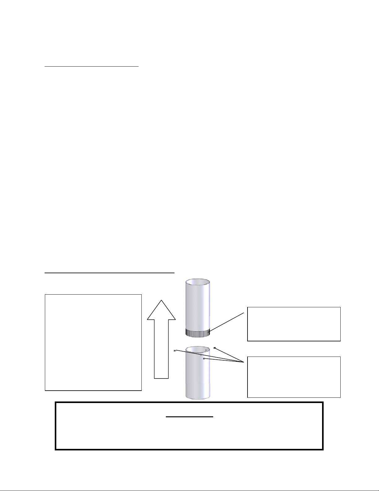
Single Wall Chimney Connector Installation
Themaleendofsinglewall
chimneyconnectoris
installedfacingdownsothat
anyliquidcreosoteinthe
fluewillrunintotheunit
insteadofontotheoutside
ofthepipe(thenaturaldraft
inthechimneysystemwill
preventsmoke leakageat
thejoints).
Crimpedormaleendof
singlewallchimney
connectormustfacedown.
Fasteneachsinglewall
chimneyconnectorjoint
withthreesheetmetal
screws.
WARNING
•
INSTALLVENTATCLEARANCESSPECIFIEDBYTHEVENTMANUFACTURER.
•
HOT!Donottouch! Severeburnsorclothingignitionmayresult.
•
Glassandothersurfacesarehotduringoperation.
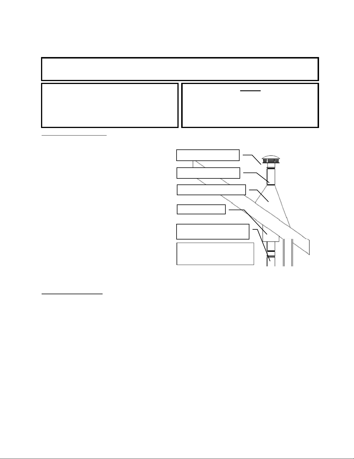
INSTALLATION
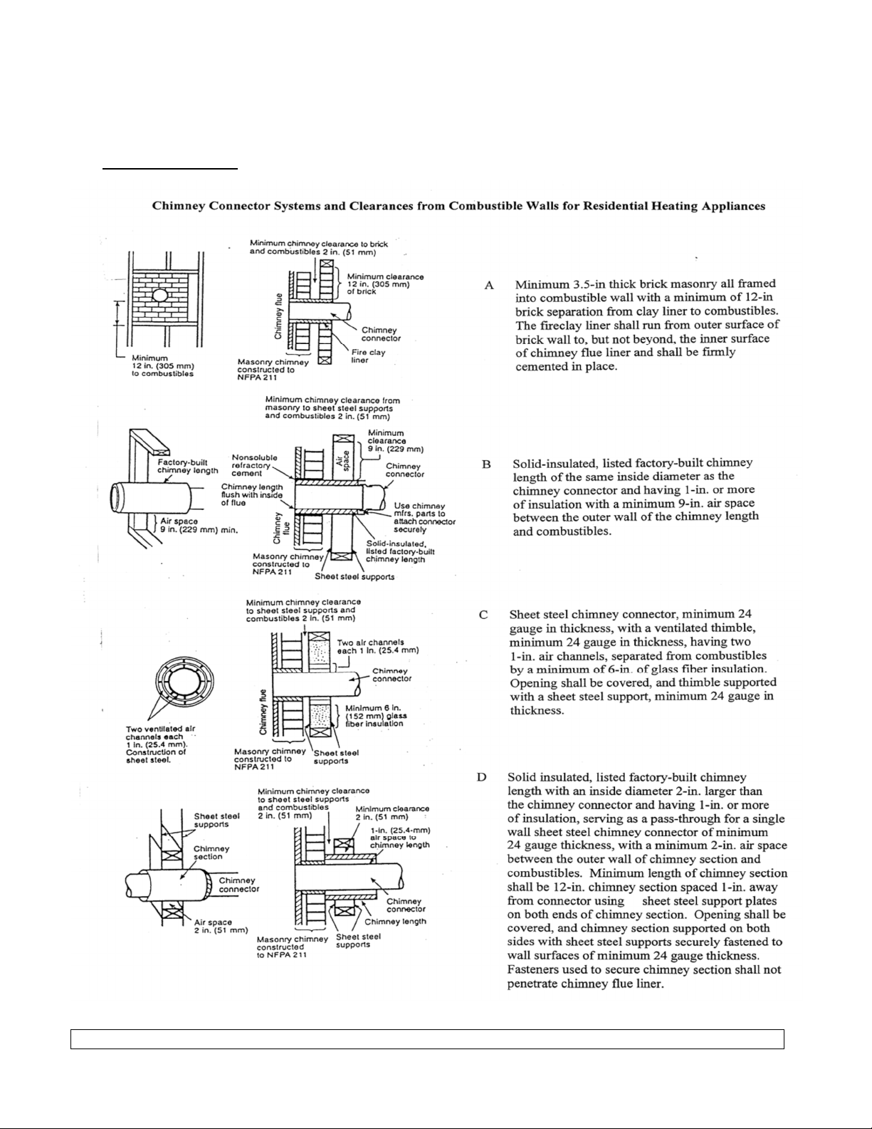
Wall
Pass-Throughs
In
Canada
, the
installation
must
conform
to CAN/CSA-8365 when passing through
combustible
construction.
Page
10
Page | 11
18.0in.
2.0ft.
3.0ft.
INSTALLATION
Approved Venting Method 1:ThroughtheWallFactoryBuiltChimney
10
ft.
TerminationCap
StormCollar
RoofFlashing
The 10‐3‐2 Rule:Thechimneysystem
mustterminate3.0ft.abovethepoint
whereitscenterlinepassesthroughthe
roofANDthechimneymustterminate
2.0ft.aboveanypartofthedwelling
withina10ft.radiusofthechimney.
WallThimble
ClassAChimneySystem
ChimneyConnector
(SingleorDoubleWall)
TeeandTeeSupport
•
PrefabricatedchimneysystemsmustconformtoUL‐103HT(2100°F)fortheU.S.andULC‐S629(650°C)for
Canada.
•
Thiswoodburningunitisonlylistedforinstallationwith6.0”diameterchimneyconnectorandchimneysystems.
Installingthisunitonprefabricatedchimneyslargerthan6.0”diameterwillresultindecreaseddraftandthe
potentialforpoorunitperformance.
•
Followallventingsystemmanufacturer’sinstallationrequir ementsandrequiredclearances.
•
Usethreesheetmetalscrewsateachsinglewallchimneyconnectorjoint(checkmanufacturer’s
recommendationswhendoublewallchimneyconnectorisused).
•
Drillthreeholesinthefluecollaroftheunitandattachthechimneyconnectortotheunitusingsheetmetal
screws(holesshouldbepre‐drilledinfluecollarfromfactory).
•
Properlyattachtheprefabricatedchimneysystemtothehomeinstrictaccordancewiththeprefabricated
chimneysystemmanufacturer’sinstructions.
•
Avoidnumerouselbowsandexcessivehorizontalrunsasbothwillleadtopoordraftandincreasedcreosote
accumulation. Horizontalrunsofchimneyconnectormustneverexceed4.0ft.andtheoveralllengthofthe
chimneyconnectormustnotexceed8.0ft.
•
Specialadaptersandslipconnectorsareavailabletoeliminatetheneedtocutsinglewallchimneyconnector.
Doublewallchimneyconnectormustbeusedwiththeseslipconnectors,asitcannotbetrimmedtolength.
Please Note:Installationdiagramsareforreferencepurposesonlyandarenotdrawntoscale,normeanttobeusedasplans
foreachindividualinstallation. Pleasefollowallventingsystemrequirements,maintaintherequiredclearancesto
combustibles,andfollowalllocalcodes.
Page | 12
2.0ft.
3.0ft.
INSTALLATION
Approved Venting Method 2:ThroughtheCeiling
10
ft.
TerminationCap
StormCollar
The 10‐3‐2 Rule:Thechimneysystem
mustterminate3.0ft.abovethepoint
whereitscenterlinepassesthroughthe
roofANDthechimneymustterminate
2.0ft.aboveanypartofthedwelling
withina10ft.radiusofthechimney.
RoofFlashing
ClassAChimneySystem
CeilingSupportBox
ChimneyConnector
(SingleorDoubleWall)
•
PrefabricatedchimneysystemsmustconformtoUL‐103HT(2100°F)fortheU.S.andULC‐S629(650°C)for
Canada.
•
Thiswoodburningunitisonlylistedforinstallationwith6.0”diameterchimneyconnectorandchimneysystems.
Installingthisunitonprefabricatedchimneyslargerthan6.0”diameterwillresultindecreaseddraftandthe
potentialforpoorunitperformance.
•
Followallventingsystemmanufacturer’sinstallationrequir ementsandrequiredclearances.
•
Usethreesheetmetalscrewsateachsinglewallchimneyconnectorjoint(checkmanufacturer’s
recommendationswhendoublewallchimneyconnectorisused).
•
Drillthreeholesinthefluecollaroftheunitandattachthechimneyconnectortotheunitusingsheetmetal
screws(holesshouldbepre‐drilledinfluecollarfromfactory).
•
Properlyattachtheprefabricatedchimneysystemtothehomeinstrictaccordancewiththeprefabricated
chimneysystemmanufacturer’sinstructions.
•
Theoveralllengthofthechimneyconnectormustnotexceed8.0ft. Inthecaseofcathedralceilings,the
prefabricatedchimneysystemshouldextendto8.0ft.fromthetopoftheunit.
•
Specialadaptersandslipconnectorsareavailabletoeliminatetheneedtocutsinglewallchimneyconnector.
Doublewallchimneyconnectormustbeusedwiththeseslipconnectors,asitcannotbetrimmedtolength.
Please Note:Installationdiagramsareforreferencepurposesonlyandarenotdrawntoscale,normeanttobeusedasplans
foreachindividualinstallation. Pleasefollowallventingsystemrequirements,maintaintherequiredclearancesto
combustibles,andfollowalllocalcodes

Page | 13
2.0ft.
18.0in.
3.0ft.
INSTALLATION
Approved Venting Method 3:InternalorExternalMasonryChimneySystem
10
ft.
Chimneylinercross‐sectional
area(LengthxWidth)must
be
nolargerthantwicethecross‐
sectionalareaofthefluecollar
(2x28.27in
2
=56.55in
2
). If
chimneylinerislargerthan
56.55in
2
,reliningwitha5.5”
or6.0”linerisrequired
The10‐3‐2Rule:Thechimneysystem
mustterminate3.0ft.abovethepoint
whereitscenterlinepassesthroughthe
roofANDthechimneymustterminate
2.0ft.aboveanypartofthedwelling
withina10ft.radiusofthechimney.
ChimneyConnector
(SingleorDoubleWall)
MasonryThimblewith
properclearanceto
combustibles
AshCleanoutsmust
haveanairtightsealto
preventweakdraft.
•
Followtheruleslistedaboveconcerningmaximumpermissiblefluelinersize;installingthisunitonmasonry
chimneysexceeding56.55
in
2
incross‐sectionalareawillresultindecreaseddraftandthepotentialforpoorunit
performance.
•
Usethreesheetmetalscrewsateachsinglewallchimneyconnectorjoint(checkmanufacturer’s
recommendationswhendoublewallchimneyconnectorisused).
•
Drillthreeholesinthefluecollaroftheunitandattachthechimneyconnectortotheunitusingsheetmetal
screws(holesshouldbepre‐drilledinfluecollarfromfactory).
•
Avoidnumerouselbowsandexcessivehorizontalrunsasbothwillleadtopoordraftandincreasedcreosote
accumulation. Horizontalrunsofchimneyconnectormustneverexceed4.0ft.andtheoveralllengthofthe
chimneyconnectormustnotexceed8.0ft.
•
Atightsealatthethimbleiscrucialforproperunitperformanceandtocreateasafeinstallation. Usetheproper
adapterdesignedforconnectingsingleordoublewallchimneyconnectortoamasonrythimble.
•
Haveexistingmasonrychimneysinspectedforsafetyandproperclearancestocombustiblesbeforeputtingthem
intoservice;aqualifiedchimneysweepcanperformthisinspection.
•
Externalmasonrychimney s oftensuffercolddowndraftsandpoordraftperformanceevenwhentheymeetthe
cross‐sectionalarearules. Inthiscase,a6.0”insulatedlinermaybenecessary.
Please Note:Installationdiagramsareforreferencepurposesonlyandarenotdrawntoscale,normeanttobeusedasplans
foreachindividualinstallation. Pleasefollowallventingsystemrequirements,maintaintherequiredclearancesto
combustibles,andfollowalllocalcodes.

Page | 14
INSTALLATION
INSTALLATION INTO A MASONRY FIREPLACE
Preparation
Measure your hearth to ensure it is large enough to accept the unit.
Unit must have a 36” clearance from the top of the stove to a mantel in accordance with NFPA 211
For the USA: Hearth must extend at least 16 in. from the front of the fuel opening.
For Canada: Hearth must extend at least 18 in (450.0 mm) from the front of the fuel opening.
Keep in mind that this type of a installation will make it difficult to change speeds on the
blower frequently. We recommend picking a blower speed and sticking with it, since
adjusting the blower will be difficult because of the tight installation.
WARNING: DO NOT ATTEMPT TO ADJUST BLOWER DURING OPERATION. SKIN BURNS
MAY OCCUR WHEN MAKING CONTACT WITH THE UNIT. WAIT FOR UNIT TO COMPLETELY
COOL BEFORE ATTEMPTING TO ADJUST BLOWER.
Inspect your hearth to be sure it is constructed of a noncombustible material such as brick or
stone. Do not install this stove on a hearth that is constructed of wood framework that is covered
by brick or stone and do not install this unit in a zero (0) clearance fireplace. The manufacturer will
not be held responsible for an accident resulting from this stove being installed on a hearth
constructed of a combustible material.
Inspect your fireplace to ensure it is in proper working order and free of any obstructions.
Prior to installation, remove the existing damper or wire it to fasten it open.
Venting Your Stove - Direct Connect
When this unit is direct connected it will require six inch (6”) diameter 24 gauge pipe from the stove
through the damper opening. (NOTE: The chimney connector must be attached to the appliance
with a minimum of three (3) screws, and 3 screws should be used to attach each adjoining
section.)
We highly recommend having the chimney fully lined with a 6 inch liner to ensure proper draft. This
will make it necessary to block off the open area on both sides of the pipe that passes through the
damper opening, which can be done with sheet metal or by packing flame retardant fiberglass
insulation in the open areas (no paper or combustibles). You must be sure the draft from the
chimney is being pulled through the stove, and not around the connector pipe. .
We highly recommend you have this done by a professional. You should also contact your local
authorities to be sure you are following all codes.
Page | 15
INSTALLATION
WARNING
DONOTINSTALLINASLEEPINGROOM.
CAUTION
THESTRUCTURALINTEGRITYOFTHE
MANUFACTUREDHOMEFLOOR,WALL
AND
CEILING/ROOFMUSTBE
MAINTAINE
D.
Caution
NEVERdrawoutsidecombustionair
from:
Wall,floororceilingcavity
or
enclosedspacesuchasanattic,garageor
crawl
space.
Mobile Home Installation(USAONLY,NOTAPPROVEDFORCANADIANMOBILEHOMEINSTALLATION)
•
ThewoodstoveMUSTbesecuredtothefloorofthemobilehomeusinglagboltsandtheholes
providedinthebottomoftheunitforthis
purpose.Usea#8copperwiretoground
stovetoframeofmobilehome.
•
Thewoodstovemustbeconnectedtothe
chimneysystemwithdoublewallchimney
connectorwhichisULlistedforusein
mobileandmanufacturedhomes.
•
Carefullyfollowallclearanceslistedinthe
appropriatesectionofthismanualANDfollow
theventingmanufacturer’s
minimum
clearance
requirements. Similarly,becertain
theventingsystemusedisapproved
formobile
homeuse.
•
Installationmustbeinaccordancewith
ManufacturersHome&SafetyStandard
ChimneyCap/SparkArrestor
ClassAChimneySystem
RoofFlashingandStormCollar
JoistShield/Firestop
MobileHomeApprovedDouble
WallChimney
Connector
Usesiliconetocreateavapor
barrierwherethechimneypasses
throughtoexterior.
(HUD)CFR3280,Part24aswellas anyapplicablelocalcodes.
Outside Combustion Air
•
Theuseofoutsidecombustionairismandatorywheninstallingthiswoodstoveinamobileor
manufacturedhome.
•
Theoutsideairconnectionpipeprotrudesfromthebottomcenterofthestove;akitisavailable
fromEngland’sStoveWorks,Inc.designedforconnectingthisunittooutsidecombustionair.[Part
No.AC‐OAK3]
•
IfitisnotfeasibletousetheAC‐OAK3outsideair hookup kitinyourstoveinstallation,other
materialsmaybeused,providedthefollowingrulesarefollowed:
o Thepipeusedforoutsideairhookupmustbemetal,withaminimumthicknessof.0209in.
(25gaugemildsteel)orgreaterandaninsidediameterofapproximately2.75in.
o Keeppiperunsshortand useamechanicalfastenerateachpipejoint.
o Ascreenorotherprotectiondevicemustbefittedovertheoutsideair termi nationpointto
preventrain,debrisandnuisanceanimalsfromenteringthepipingsystem. Inspectthe
outsidecombustionairinletforblockanddebrismonthly.
Page | 16
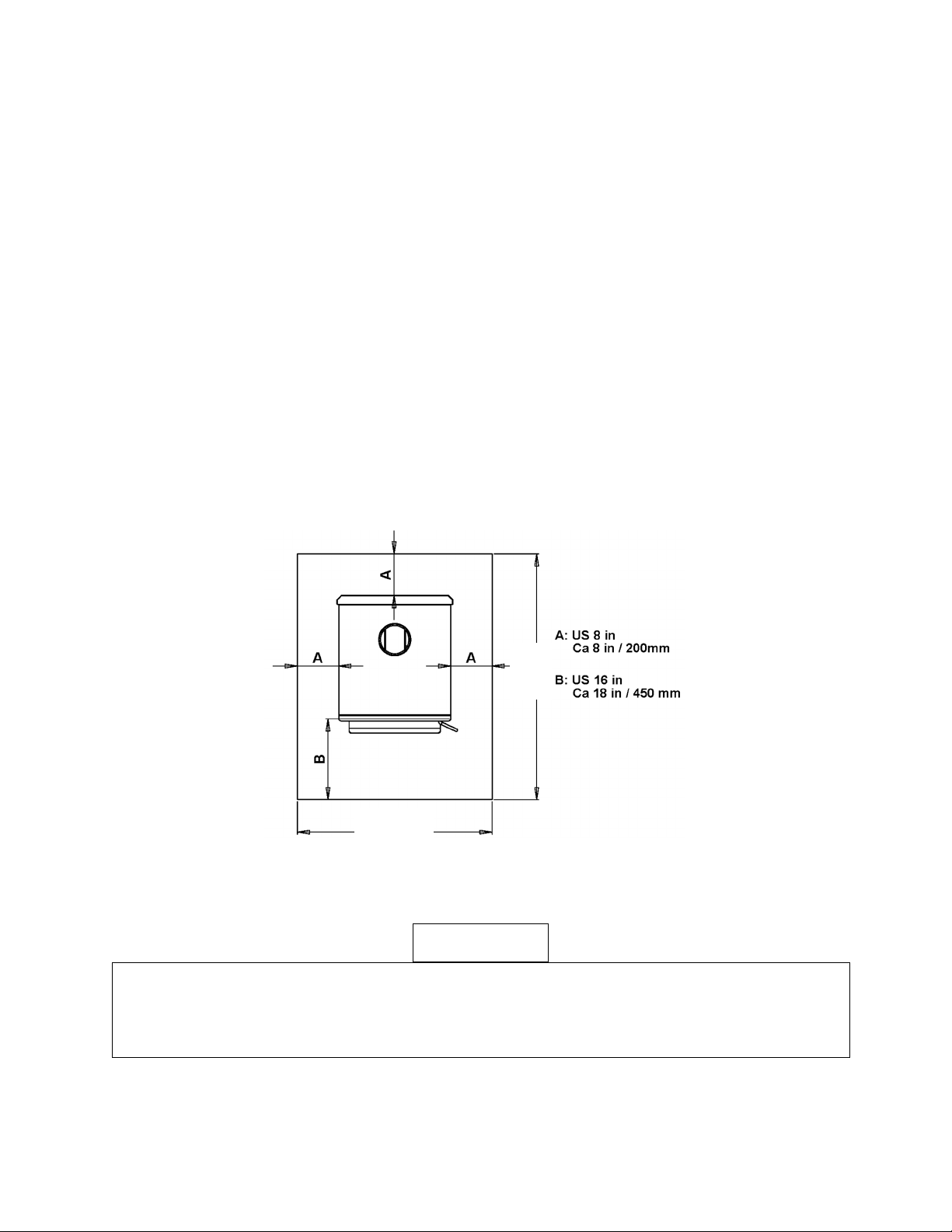
FLOORPROTECTION
•
ThiswoodstoverequiresaULlistedtype1sparkandemberfloorprotectorifthestoveistobe
installedonacombustiblefloor. Ifthefloorthestoveistobeinstalledonisalready
non‐combustible(i.e.aconcretefloorin abasemen t),nofloorprotectionis
needed(althougha
decorativefloorprotectorcanstillbeusedforaestheticreasons).
•
WhenusinganyULli stedtype1sparkandembe rfloorprotector,considerthatthisstoveisnotonly
heavybutwillinduceheatingandcoolingcyclesonthefloorprotectorwhichcandamagetileand
loosenmortarandgroutjointslocatednearthestove.
•
Thespar kandem berfloorprotectorshouldbeULapprovedorequivalent(ULCifCa nada) andmust
benoncombustible. Sincethemajorityoftheheatfromthisunitisradiant,thefloorprotectoronly
servestokeepashesandsparksfromlandingoncombustibleflooringneartheunit. Ahearth
rugis
NOTanapprovedsubstituteforaproperhearthpad.NoRValueisnecessary.
•
FortheUS:Thefloorprotectormustextendatleast16in.fromthefrontofthefuelopening,8in.
fromthesidesofthedooropeningand8in.fromtherearoftheunit.
•
ForCanada:Thefloorprotectormustextendatleast450.0mmfromthefrontofthefuel
opening,
200.0mmfromthe sidesofthedooropeningand200.0mmfromtherearoftheunit.
•
Thesparkandemberfloorprotectormustextend2in.(50.8mm.)oneithersideofanyhorizontal
ventingrunsandextenddirectlyunderneathanyverticalventingpipe.
CAUTION
NEVERUSEGASOLINE,GASOLINE‐TYPELANTERNFUEL,KEROSENE,CHARCOALLIGHTER
FLUID,
ORSIMILARLIQUIDSTOSTARTOR“FRESHENUP”AFIREINTHISHEATER. KEEPALL
SUCH
LIQUIDSWELLAWAYFROMTHEHEATERWHILEINUSE. ADDITIONALLY,NEVERAPPLY
FIRE‐
STARTERTOANYHOTSURFACEOREMBERSINTHE
STOVE.
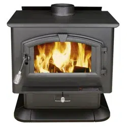
38½in
47in

Page | 17
OPERATION
Break‐In Fires
•
Thiswoodburningunitisconstructedofheavygaugesteelandcastironandisbuilttolastalong
time. However,inordertoensurenoexcessivethermalstressesareinducedonthe
metal
during
thefirstfire,threebreak‐infiresshouldbeburned,eachoneslightlyhotterthanthelast.
Thesebreak‐infireswillnotonlyhelpthestovebodyacclimatetothehightemperaturesofthe
fire,butwillalsoslowlycurethehightemperaturestovepaint,whichwillensurethe
high
qualityfinishlastsforyears.Remembertoopenadoorand/orwindowtoventilatethearea.
•
Thisstovehasasingleaircontrolrodwhichregulatesthewoodburnrate;whentheprimaryair
controlslideispulledallthewayoutoftheunit,thestovewillburnmoreslowlyandputout
heatoveralongertimeperiod. Conversely,whentheaircontrolslide
ispushedallthewayin,
theunitwillburnmorequicklyandputoutalargeramountofheatoverarelativelyshorter
time
period. Donotattempttomodifytherangeofaircontroladjustmentforanyreason.
•
Thefirstbreak‐infireshouldbejustalargekindlingfire,gettingthestovetoabout300°Fas
measuredbyamagneticthermometerontherightorleftsideofthestove,abovethe
door.
Once
thistemperatur ehasbeenreached,allowthefiretodieoutwiththeaircontrolopen.The
secondandthirdbreak‐infiresshouldbeabitlarger,withsomesmalldrysplitsaddedtothe
kindlingload. Thetemperaturegoalduringthesefiresisabout350°F–450°
F;don’tletthefire
gethotterthanthat.
Continuous Operation
•
Afterthebreak‐infiresarecomplete,thisunitisreadyforcontinuousoperation. Whenburning
thestovecontinuously,donotallowashandcoalstoaccumulatehigherthantheairholeinthe
dogbox. Excessivecoalingisoftenaresultofburningwoodattoohighaburn
rate,andthe coal
bedshouldbeallowedtoburndownbeforereloadingthestovewithfreshwood.
•
Combustionairisdeliveredtothestoveattwolocations:Themajorityoftheprimarycombustion
airentersthefireboxviatheair‐washsystemwhichkeepstheglasscleanandfeedstheprimary
combustionflamesonthetopsurfacesofthewood;someprimar ycombustionairisfeedinto
the
coalbedviathedogboxholeinthebottom,frontboxofthestove. (Thisairissuppliedfrom
undertheunit.)Everyeffortmustbetakentomaintaintheareainfrontofthisholefreeofash.
•
Whenloadingthestoveforalongtermburn,itismostusefultorakea“v”inthecenterofthe
coalbed,toallowtheprimaryairbleedholetopushairallthewaytotherearoftheunit.
•
Afterloadingthestovewithafullfireboxoffreshwood,itisimportanttooperatetheunitwith
theaircontrolinthefullopenpositiontoproperlycharthewoodloadanddriveofftheinitial
moistureinthefreshwood. Oncethewoodhasbeenproperlycharred
andiscompletely
ignited,theaircontrolcanthenbesettothedesiredheatoutputlevel.
•
Thisunitalsooffersanewfeature. Whenloadingthestoveforalonglowburn,youcansetthe
aircontroldampertoallowtheunittoheatupandgetagoodburngoingbeforetheairis
closed
offtothelowposition. Simplypulltherodouttolowandturnitcounter‐clockwiseuntil
youhearaslight “click”(aboutaquarterofaturn). Whenitisreadythedamperwillshutitself.
Thiswillworkforlowandmediumlowsettings.
age | 18
OPERATION
•
England’sStoveWorks,Inc.alwaysrecommendstheuseofamagneticstovethermometer,so
thatthetemperatureoftheunitcanbemonitored. Whenusingamagneticstovethermometer,
locatethethermometerabovethedooroneithertheleftorrightsideofthestoveandusethe
followingtemperatures
asroughguidelinestodeterminetheburnrateandheatoutputlevelof
thestove:
o Normalwoodstoveoperationshouldoccurbetween350°F(177°C)and550°F(288°C),
with350°F(177°C) to450°F(232°C)beingalowtomediumheatoutputleveland450°F
(232°C)to550°F(288°C)beingamedium
tohighheatoutputlevel. Operatingthestove
at600°F(316°C)wouldbeconsideredthemaximumcontinuousoperatingtemperature
permissibleandunitdamagemayresultfromoperatingatthathighofaburnratefor
extendedtimeperiods. Allowingtheunittoreach650°F(343°C)orhigherisdefinedas
over
‐firingandwillresultinunitdamage.
•
Theoptionalroomairconvectionblowerwasdesignedtoextractthemaximumamount ofheat
fromthestove,forthehighestpossibleheattransferintotheroom. Sincetheblowerisso
efficientatremovingheatfromtheunit,itisveryimportanttoonlyoperatetheroomairblower
afterafreshwoodloadhasbeenallowedtoburnforatleastthirty(30)minutes. Allowingafresh
loadofwoodtoburnwithoutthebloweronensuresthattheentireunitreachesproper
operationtemperaturesandthatthesecondarycombustionsystemisfunctioningproperly.
Additionally,followtheguidelinesbelow
foracceptableblowerspeeds.
•
Whenusingtheoptionalroomairconvectionblower(PartNo.AC‐16,oryoucanupgradetothe
AC‐30),theblowershouldbeoperatedasfollowsdependingonheatoutputlevel:
Burn
Rate
High MediumHigh Medium MediumLow Low
BlowerSpeedAC‐16 High
High
Low
Low
Low
BlowerSpeedAC‐30 High MediumHigh Medium MediumLow Low
Creosote – Formation and Need for
Removal
Whenwoodisburn edslowly,itproducestarandotherorganicvapors,
which
combinewithexpelledmoistureto formcreosote. Thecreosote
vapors
condenseintherelativelycoolchimneyflueofaslow‐burningfire. Asa
result,
creosoteresidueaccumulatesonthefluelining. Whenignited,this
creosote
makesanextremelyhotfire. Thechimneyandchimneyconnectorshould
be
inspectedatleastonceeverytwomonthsduringtheheatingseason
to
determineifacreosotebuilduphasoccurred. Ifcreosotehasaccumulated,
it
shouldberemovedtoreducetheriskofchimney
fire.
DONOTUSEGRATEORELEVATEFIRE–BUILDWOODFIREDIRECTLYON
HEARTH
DONOTOPERATEWITHTHEMAINDOOROPEN–OPERATINGTHESTOVEWITHTHE
MAIN
DOOROPENWILLCREATEANOVER‐
FIRE
Intheeventofacreosoteorsootfire(chimneyfire),closetheaircontrolonthe
stove,
contactthelocalfiredepartmentandgetout! Donotthrowwateronthefire!
Contact
yourlocalfireauthorityformoreinformationonhowtohandleachimneyfire
and
P
developasafeevacuationplanforyouandyourfamilyintheeventofachimneyfire.

Page | 19
OPERATION
Additional Safety Guidelines
CAUTION:Whenaddingfueltothestove,theblowermustbeturnedOFF.
•
Theinstallationofsmokedetectorsishighlyrecommendedwheninstallingthisoranyothersolid
fuelburningappliance. Smokedetectorsshouldbelocatednearorineveryroomofthehome,
particularlysleepingrooms.
•
Asmokedetectorcanbeinstalledinthesameroomasthiscordwoodburningunit;installingthe
smokedetectortooclosetotheunitcanleadtonuisancealarmsduetoslightwispsofsmokeemitted
duringthefirestartingorreloadingprocess. Duetothis,thesmokedetectorin
the
sameroomastheunitwillbemostusefulifitislocatedas farfromtheunitastheroomwill
permit.
•
Thisstoveisdesignedtoburnnaturalwoodonly.Higherefficienciesandloweremissionsgenerally
resultwhenburningairdried,seasonedhardwoods,ascomparedtosoftwoodsortogreenor
freshly‐cuthardwoods.DONOTBURNgarbage,lawnclippingsoryardwaste,materialscontaining
rubber,includingtires;Materialscont aining
plastic:Wasterpetr oleumproducts,paintsorpaint
thinners,orasphaltprod ucts; Materialscontainingasbestos;Constructionor demolitiondebris;
Railroadtiesorpressure‐treatedwood;Manureoranimalremai ns;Saltwaterdriftwoodor
previouslysaltwatersatu ratedmaterials;Paperproducts,cardboard,plywood,orparticleboard.
Theprohibitionagainstburningthesematerialsdoesnot
prohibittheuseoffirestartersmade
frompaper,cardboard, sawdust,waxandsimilarsubstancesforthepurposeofstartingafirein
anaffectedwood heater.Burningthesematerialsmayresultinreleaseoftoxicfumesorrender
theheaterin effectiveandcausesmoke.
•
Burningfuelsotherthancordwood,particularlycoalandcharcoal,canresultinhazardous
concentrationsofcarbonmonoxidebeingemittedintothedwelling. Forthesereasons,NEVER
burncoalorcharcoalinthiscordwoodstove.Installingacarbonmonoxidedetectorandbeing
awareofthesymptomsofcarbonmonoxidepoisoning can
helpreducetheriskofcarbonmonoxide
relatedissues.
•
Thisunitwasdesignedforoperationonlywiththeloadingdoorclosedandtightlylatched.
Operatingthisunitwiththeloadingdoorlatchedlooselyoropenwillallowexcessivecombustionair
toreachthefireandwillresultindangerouslyhighunittemperatures. Highunittemperaturescan
damagetheunit,
voidthewarrantyorignitecreosotedepositedinthechimneysystembyprevious,
slowburningfires.
•
Thenaturaldraftthatpullsairthroughthisunitandallowsthefiretoburnusestheindoorairofthe
dwellingforcombustion,unlesstheunitisconnectedtoanoutsidecombustionairsource.Kitchen
rangeventhoods,furnacesandotherairmovementappliancesinthehomeareoften
alsoremoving
airfromthedwelling;iftheamountofairfiltrationorleakagebackintothehomeisexceededbythe
airbeingremoved,negativepressure maybecreatedinthehome.
•
Sincethisisanaturaldraftappliance,itwilloftenbethefirstappliancetohaveproblemsrelatedto
negativepressure. Ifsmokeisforcedoutthechimneyconnectorjointsoroutoftheairinduction
systemoftheunit,theunitislikelyfightingnegativepressureinthedwelling.
Crackingawindowordoorneartheappliancecanhelpequalizethenegativepressure;
ultimately,anunrestrictedsourceofoutsidecombustionmaybenecessaryforproperunit
DONOTSTOREFUELCLOSERTHANSPECIFIEDCLEARANCESTOCOMBUSTIBLESOR
WITHINTHESPACENEEDEDFORLOADINGTHESTO
V
EANDFORASHREMO
V
AL.

Page | 20
function.
•
Iftheunitisconnectedtooutsideair, becertaintomonitortheexteriorinlettothecombustion
systemforicingorsnowa c cumulation. Allowingtheoutsideairconnectionto
becomerestricted
will
resultinairstarvationtotheunit.
SafeWood‐BurningPractices
Onceyourwood‐burningapplianceisproperlyinstalled,followtheseguidelinesforsafe
operation:
Keepallflammablehousehoulditems‐drapes,furniture,newspapers,andbooks‐far
awayfromtheappliance.
Startfiresonlywithnewspaper,drykindlingandallnaturalororganicfirestarters.
Neverstart
afirewithgasoline,kerosene,orcharcoalstarter.
Donotburnwetorgreen(unseasoned)logs.
Donotuselogsmadefromwaxandsawdustinyourwoodstove‐theyaremadeforopen
hearthfireplaces.Ifyouusemanufacturedlogs,choosefromthosemadefrom100percent
compressed
sawdust.
Buildhotfires.Formostappliances,asmolderingfireisnotasafeorefficientfire.
Keepthedoorstoyourwood‐burningapplianceclosesunlessloadingorstokingthelivefire.
Harmfulchemicals,likecarbonmonoxide,canbereleasedintoyourhome.
Regularlyremoveashesfromyour
wood‐burningapplianceintoametalcontainerwitha
cover.Storethecontainerofashesoutdoorsonacementorbrickslab (notonawooddeck
ornearwood).Seeashremovalinstructionsinyourowner’smanual.
Keepafireextinguisherhandy.
Remembertocheckyourlocalairqualityforecast
beforeyouburn.
Page | 21
Daily Maintenance
MAINTENANCE
•
Inspectthefireboxforashaccumulation;removeexcessashandfollowinstructions
belowregardingdisposal.Ashshouldnotbeallowedtoaccumulateinthestovetothe
pointthatitcoversthedogboxhole.
Monthly Maintenance
•
Checktheblowerfordustaccumulation(ifinstalled);checkthedoorhandleforproper
operationandtobecertainanairtightsealisstillbeingmadebythedoor.
•
Inspectthechimneysystemandchimneyconnectorandsweepifnecessary. Although
cleaningmayberequiredlessthanmonthly,ALWAYSinspecttheventingsystem
monthlytodecreasethechanceofachimneyfire.
•
Visuallyinspecttheceramicfiberinsulatingboardsinthefireboxforcracksand/or
breakage. Slightsurfacecrackswillnotaffecttheperformanceoftheboards,but
crackedorcrumblingboardsshouldbereplacedimmediately.
•
Visuallyinspectthesecondarycombustiontubesforcracks,warpingandcorrosion.
Althoughthesetubesareconstructedfromstainlesssteel,theyoperateatveryhigh
temperaturesandcaneventuallywearoutfromnormaluse.
Yearly Maintenance
•
Checkallgaskets(windowanddoor)forwearandtobecertaintheystillmaintainan
airtightseal. Seethefollowingpageforinstructions.
•
Thoroughlycleanthechimneysystemandthechimneyconnectorsystem. Sincethe
chimneyconnectorisgenerallyexposedtohighexhausttemperatures,inspectit
carefull
y
forleaksandweakspots;replaceanyquestionablepieces.[Inthecaseof
straightthroughtheroofchimneysystem,becertaintoremovetheceramicfiberbaffles
beforepushingthechimneysweepingbrushdownintothefirebox. Forcefullyhitting
thetopofthebafflewithacleaningbrushorrodcandamageordestroythebaffle.]
•
Removeallashfromthestove,includingtheashwhichaccumulatesonthetopofthe
fireboxbaffles. Leavetheaircontrolopenduringthenon‐heatingmonthstoallow
someairtoflowthroughthestovetohelppreventcorrosion.Asmallopencontainerof
catlitterinthestovecanhelppreventcorrosionduringthehumidsummermonths;be
certaintoremoveitbeforebuildingafireinthefall.
IMPROPERGASKETMAINTENANCE,INCLUDINGFAILURETOREPLACEGASKETS,CAN
CAUSEAIRLEAKSRESULTINGINANUNCONTROLLABLEFIREINTHEUNIT.
DisposalofAshes–Ashesshouldbeplacedinametalcontainerwithatightfittinglid. The
closedcontainerofashesshouldbeplacedonanoncombustiblefloororontheground,well
awayfromallcombustiblematerials,pendingfinaldisposal. Iftheashesaredisposedofby
burialinsoilorotherwiselocallydispersed,theyshouldberetainedintheclosedcontainer
untilallcindershavebeenthoroughlycooled.

Page | 22
Inspecting Gaskets
MAINTENANCE
Anairtightsealatthedooropeningiscrucialtoproperstoveperformance. Anyairleakage
atthisareacancauseanover‐firesituationandisthereforeaserioussafetythreat. Becauseof
this,gasketsshouldalwaysbemaintainedingoodcondition. Gaskettightnesscanbechecked
usingthe“dollar‐bill”method:
•
Placeadollarbillbetweenthegasketandthe stovebody(atthelocationwherethe
gasketmeetsthestove).
•
Closeandtightenthedoorthenattempttopullthedollarbillout. Ifthedollarbillslides
inandouteasily,thegasketneedstobereplaced. Thistestshouldberepeatedaround
theentiregasketperimeter,asgasketswillsometimessealtightlyononeside,butwill
be
wornandsealpoorlyonanotherside.
•
Performthistestaroundtheentireperimeterofthedoor,andvisuallyinspectthe
windowgasketforanyleaks. Leaksinthewindowgasketcangenerallybelocatedby
followingtheprevailingsoottrailsleftonthewindowafterburningtheunit.
•
Ifanyareafailsthetest,theentiregasketshouldbereplaced. Thepartnumber
appropriatetothegasketbeingreplacedcanbefoundinthe“IllustratedParts”section
ofthismanual.
•
Gasketsshouldonly bereplacedwithequivalentfiberglassgasketspurchasedfrom
England’sStoveWorks®specificallyforthisunit.
Gaskets
1. Door‐Thisunitcomeswitha¾“ropegasketaroundthedoorthatshouldbereplaced
atleasteveryyear.Toreplacethedoorgasket(Part#AC‐DGKHD),theoldgasketmust
firstberemovedentirely—priortoaddingthenewadhesive,youmayhavetoscrape
theoldcementfromthedoorchannel.Oncethecementandgaskethavebeenadded,
thedoorshouldbeclosedandlatchedfortwenty‐fourhourstoallowthecementto
harden.
2. Window‐Ifyouarereplacingthewindowgasket(Part#AC‐GGK),thenewgasketwill
alreadyhaveadhesiveononeside. First,removetheoldgasket. Next,removethe
paperontheadhesivesideandplacethegasketaroundtheoutsideedgeoftheglass,
centeredovertheedge. Foldthegasketedgesoverontheglass,forminga“U”shape.
Finish
ThisnewunithasbeenpaintedwithHigh‐TemperaturePaintthatshouldretainits
originallookforyears.Iftheunitshouldgetwetandrustspotsappear,thespotscanbesanded
withfinesteelwoolandrepainted.ItiscrucialthatonlyHigh‐TemperatureSprayPaintisused
(Part#AC‐MBSP),asothersmaynotadheretothesurfaceorwithstandthehightemperatures.
Similarly,somebrandsofpaintwillnotadheretodifferentbrandsofpaint,sowehighly
recommendusingourproprietaryHigh‐TemperatureSprayPaint.

Page | 23
Glass
REPLACINGCOMPONENTS
Thisunithasaceramicglasspanel(PartNo.AC‐G50)intheviewingdoor;selfadhesive
windowgasketisincludedwithreplacementwindowspurchaseddirectlyfromEngland’sStove
Works.Neverreplaceceramicglasswithtemperedoranyothertypeofglassandneveroperate
thisunitwithcrackedorbrokenglass.
•
GlassSize:12.75in.(323.85mm)x16.75in.(425.45mm)
•
GlassType:5mmCeramicGlass(KeralitePyroceram)
•
GlassManufacturer:Eurokera
Glass Precautions
1.Neverreplaceceramicglasswithtemperedoranyothertypeofglass.
2.Neveroperatethisunitwithcrackedorbrokenglass.
3.Donotslamthedoororstriketheglasswithanyobjects.
4.Donotbuildthe firedirectlyagainsttheglass.
Glass Cleaning
1.Becertainthestoveandthe glassarecompletelycool.
2.Thebuild‐upontheglasswillgenerallybelightandwaterisnormallysufficientto
removethedeposits.Ifstubbornsootpersists,useacleanermadespecificallyforthis
purpose. Donotscrapetheglassoruseabrasivecleaners.
3.Rinsethe glasswithcleanwateranddrytheglassbeforeresumingnorm aloperation.
Glass Replacement
1.Removethedoorfromthestoveandrestitfacedownonafirmworksurface.
2.Usinga5/16”wrench,removethefourwindowbracketretainingscrews.
3.Removethefourwindowtabsfromthedoor. Takeextracaretoavoidshardsofglassif
theglasswindowhasbeenbroken.
4.Lifttheoldglasspaneloutofthedooranddiscard.
5.Theglasspanelmustbewrappedwithaself‐adhesivefiberglasstapegasket(AC‐GGK).
Ifyoupurchasedanewglass,itwillcomealreadywrapped. Ifreusingthesamepiece of
glass,removeoldgasket,scrapeoffoldadhesiveandwrappedwiththeAC‐GGK. This
gasketservestocushiontheglassfromthecastirondoor.
6.Reinstallthewindowretainingtabsusingthefourscrewspreviouslyremoved. Donot
over‐tightenthescrews.

Page | 24
Burner tube replacement
REPLACINGCOMPONENTS
Therearethreedifferentburnertubesinthetopofthestove. Toreplaceatube,first
besurethatyouorderthecorrecttubeyounee dtoreplace. Thenusinga5/16”socketor
openendwrench,removethescrewlocatedontheleftsideofthetube. Besuretokeepthe
screw.
Push the tube to the right then remove the tube (pulling the tube back to the left
after that side
has been removed from the hole). To replace, reverse the above
procedure...makesuretoinstallthetubesinthecorrectorder.(FronttoBack)
Ceramic fiberboard replacement
Toreplaceacrackedorbrokenboard, first
removethefrontburnertube. Thenremovethe
boardyouneedtoreplace. Installthenewboard
(thetwoboardsshouldsitflushonthetubesside
byside). Replacethetubepreviouslyremoved.
Door hinges
Thehingesonthisunitweredesignedtobeadjustable. Theplatesaresecuredusinga
½”boltandnut. Toadjustthehing eplatesinoroutfirstremovethedoor,thenusea½”socket
and½”openendedwrench(oneonthenutandoneonthebolthead)andloosenthebolt/nut.
Slidetheplatein/outasdesiredandthenusethesocketandwrenchtotightenthebolt/nut.*
Usecarewhenadjustinghinges. Ifenoughroomisnotleftforthedoortoclearthesideofthe
unit,thehingecouldbreak.*
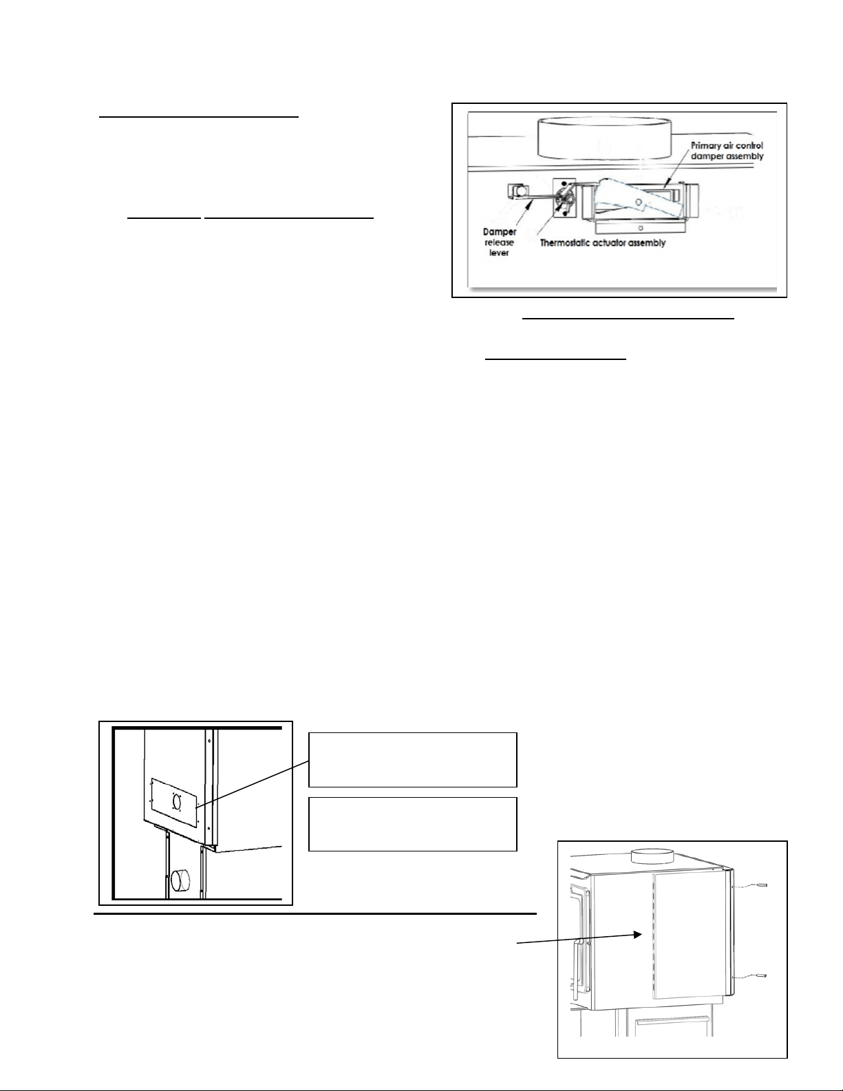
Heatshieldandbackpanelremoval(toaccessothercomponents)
Therearetwo5/16”screwsthatareontherearoftheheatshield. Toremovetheheat
shield,usinga5/16”socketoropenendedwrench,removethetwoscrews. Thenpulltheheat
shieldupandbackoffthebackpanel. Nexttoremovethebackpanel,therearethree5/16”
screwsontherearofthepanel. Usinga5/16”socketoropenendedwrench,removethethree
screws. Itmaybenecessarytoprythetopofthepanelwithaflatheadscrewdriver(atthetop
ofthestove). Liftthepanelupandoffthestove.
Page | 25
Other Components continued:
Atthispointyoucanaccesstheprimaryaircontrol
damperassembly,thermostaticactuatorassembly
andthedamperreleaselever. Althoughthese
shouldn’tneedtobereplaced,theycanbeeasily.
Theprimary aircontrol da mper assemblycanbe
replacedbyremovingthesmallspringhandle
fromthefrontoftheunit,thenslidingthe
assemblyout. Re placebyslidingthenew
assemblythroughthesameholeandtherod
throughthe
frontofthestove. Replacethespringhandle. Thethermostatic actuator assembly
canbereplacedbyusinga5/16”socketto removethetwoscrewsthatholdtheassembly.
Installthenewassemblyusingthe
sametwo
screws. Thedamper release levercanbereplaced
byremovingthe½”bolt. Whenreinstallingthedamperbesureitisinstalledthesameaswhen
removed.
OPTIONALACCESSORIES
Blower:Thewoodstovewasalsodesignedforusewithaconvectionblowerforadditionalheat
circulation. Thestoveisconstructedwithsideconvectionchannelswhichallowtheroomair
blowertopickupheatfromthehottestregionsofthestoveandtransferitintothehome. The
mountingscrewsfortheblowerareinstalledintotherearconvectionchannelatthefactory;
mountingthebloweronlyrequiresa5/16”openendorsocketwrenchtoremovethesescrews
andinstalltheblower. Whenroutingthepowercord,takecaretokeepawayfromhotareasof
theunitandrememberthatthisblowerisforuseonlywiththestove. Pleaseseethediagram
belowforclarificationontheroomairblowerinstallation. ThisunitcanusetheAC‐16(which
comesstandardwiththeunit)ortheAC‐30upgradeblower.Bothareinstalledusingthefour
factoryinstalled5/16”screws.
Theoptionalheatcirculationbloweronthisstoverequiresperiodiclubrication;thislubricationshouldbeperformed
nolessthaneverythreemonthsofnormaloperation. Toproperlylubricatetheblower,useaneyedropperor
similardispensingdevicetodrip5‐7dropletsofSAE20oilinto
theoil
portonthesideoftheblowermotor
SideHeatShield(PartAC‐W01SHS):
Installthesideheatshieldbehindthesideflangeoftherearpanel.Align
thetwomountingholesandsecurewiththetwoscrewsprovided.
Warning:Disconnectpower
fromfanbeforeinstallation.
(4)5/16”head,self‐tapping
screws(pre‐installedinunit).

Page | 26
TROUBLESHOOTING
Issue Cause Solution(s)
Stovesmokesintoroom 1.WeakDraft 1.1Becertainchimneyissufficientlytallto
meetthe10‐3‐2rule.
1.2Addadditionalheighttothechimney.
2.NegativePressurein
theHome
2.1Addanoutsidecombustionairhookupto
theunit.
Fireishardto
start 3.WeakDraft 3.1Becertainchimneyissufficientlytallto
meet10‐3‐2rule.
3.2Addadditionalheighttothechimney
system.
4.ColdChimney 4.1Heatthefluefirstbyburningcrumbled
newspaperinthestove.
4.2Installaninsulatedchasearoundexternal
chimneys.
5.Downdraft
in
Chimney
5.1Becertainchimneyissufficientlytallto
meet10‐3‐2rule.
5.2Tryheatingthefluewithahair‐dryerto
correctthedraft.
Glassisdirty 6.WetorGreenWood 6.1Onlyburnwoodthatisseasonedforat
leastoneyearandthatis
dryandfreeofice
andsnow.
7.OperatingStoveat
LowBurnRate
8.WoodLoadedToo
ClosetoGlass
Coalsbuildupinfirebox 9.OperatingStoveat
HighBurnRates
7.1Operatethestoveathigherburnratesto
allowtheair‐washsystemtokeeptheglass
clean.
8.1Neverloadwoodsothatitistouchingthe
ceramicglassviewing
window.
9.1Reducecombustionaircontrolandallow
coalstoburndownbeforereloading.
Fireburnsoutofcontrol 10.ExcessiveDraft 10.1Reducechimneyheight.
11.AirLeakage 11.1Inspectwindowanddoorgasketsand
replaceifnecessary.
12.BurningExcessively
DryWood
Excessivesmokefromstack 13.Operating
Stoveat
LowBurnRate
14.WetorGreen
Wood
15.NotCharringFresh
WoodLoad
12.1Onlyburnseasonedcordwood. Donot
burnkilndriedwoodorpalletwood.
13.1Operatethestoveatahigherburnrate
whichwillcreatesecondarycombustion.
14.1Onlyburnwoodthatisseasonedforat
leastoneyearandthatisdry
andfreeofice
andsnow.
15.1Charthefreshwoodloaduntilitis
completelyignitedandactivesecondary
combustionispresentinthefirebox.

Page | 27
REPLACEMENT PARTS LIST
Diagram
No.
Description
PartNo.
Per
Unit
7
Rearheatshield(BOLTON) AC‐W01HS
1
6
Rearpanel(BOLTON) AC‐W01RP
1
1
Primaryaircontroldamperassembly AC ‐W01PDA
1
Notshown Damperreleaselever AC‐W01DRL
1
Notshown Thermostaticactuator assembly AC‐W01TAA
1
9
Ash
drawer
AC‐ADW01
1
10
Door
CA‐W01
1
14
Door
hinges
AC‐DHW01
2
Notshown Sideheatshields
AC‐W01SHS 2
Notshown LargeUpgradeBlower(optional)
AC‐30
1
Notshown Smallstandardblower
AC‐16
1
12
Glassgasketkit3/4"flat AC‐GGK
1
16
Doorgasketkit3/4"highdensity AC‐DGKHD
1
3
Frontburnertube AC‐W01FBT
1
17
Middleburnertube AC ‐W01MBT
1
4
Rearburnertube AC‐W01RBT
1
13
Glasssize12.75”X16.75” AC‐G50
1
2
Ceramicfiberboard AC‐W01CFB
2
Notshown SmallspringhandleNickel/Brass AC‐SH4N/AC‐SH4
1
Notshown LargespringhandleNickel/Brass AC‐SHN/AC‐SH
1
8
Blowerbackcover AC‐BBC30
1
15
Glass
tabs
AC‐W01GT
4
11
Hinge
pins
AC‐HP
2
Notshown
OutsideAirKit(optional)
AC‐OAK3 1
*FOR BRICK LAYOUT AND PART NUMBERS PLEASE
SEE PAGE 29.*
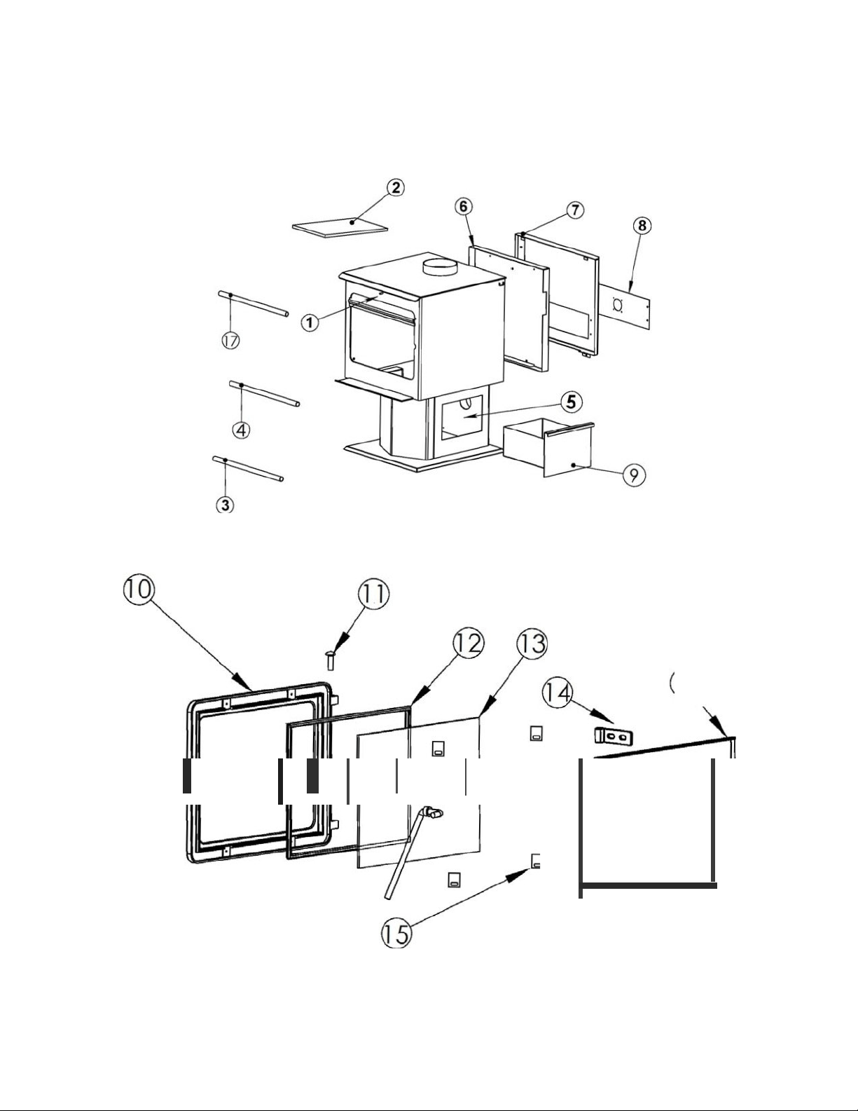
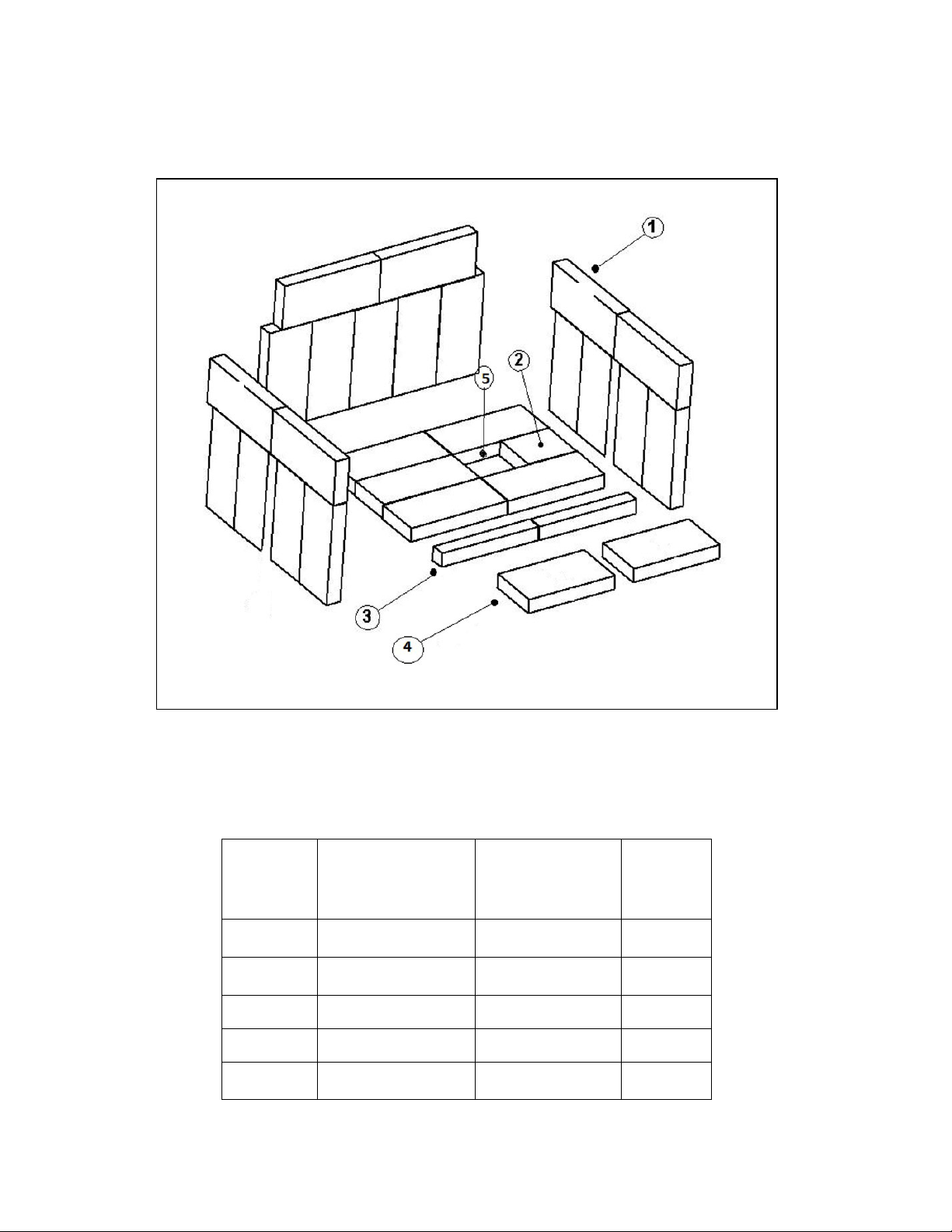
Page | 28
ILLUSTRATED PARTS
DIAGRAM
16
Pa
g
e
29
BRICK LAYOUT AND REPLACEMENT
NOTE:Thebricksonthesidesandrearwillneedtobeinstalledafterdelivery
*Toprearbricksoneachsidemayormaynotbenotched.Ifnotched,order
partnumberAC‐SBN1X3.
DIAGRAM
NUMBER
BRICKSIZE
PARTNUMBER
QUANTITY
PER
STOVE
1 9"X4"X1.25"
AC‐SB
24
2 4.5”X4”X1.25” AC‐SB4.5
1
3
7.75”X2.25”X1.25” AC‐SB7.75X2.25
2
4 7.75”X4”X1.25” AC‐SB7.75
2
5
ASHDUMPPLUG
CA‐30ADP
1
*
*

Page | 30
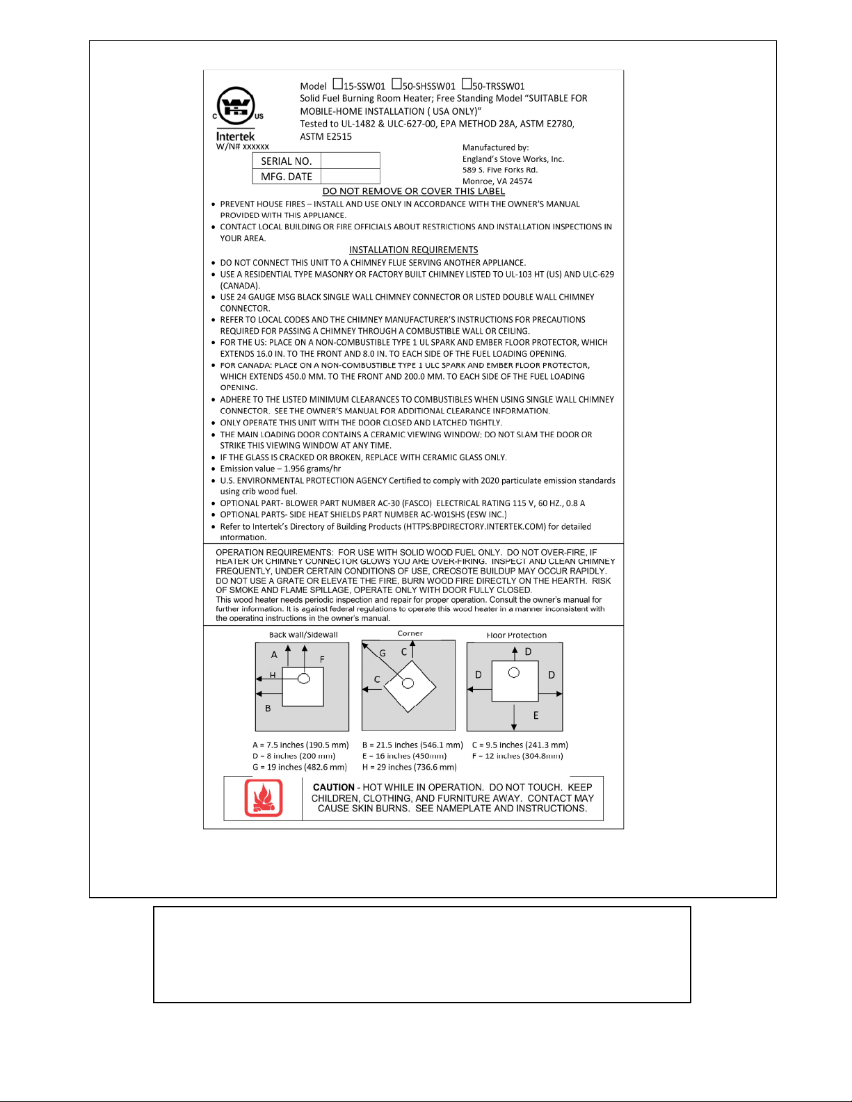
You may write your unit’s Manufacture Date and Serial Number in the blank
spaces on this sample tag, for future reference. This sample tag also
shows
the
safety info. such as UL (ULC) testing standard, etc. for your local
officials, or anyone else who may need reference information.

Warranty is not transferable.
Page | 31
LIMITED FIVE (5) YEAR
WARRANTY
Fromthedateofpurchasetotheoriginal
owner
Themanufacturerextendsthefollowingwarranties:
Five Year Period:
1. Carbonsteelandweldedsea msinthefireboxarecoveredforfive(5)
yearsagainstsplitting.
2. Thecastirondoorandhingesarecoveredforfive(5)yearsagainst
cracking.
One Year Period:
1. Electricalcomponents,accessoryitems,glassandthepaintedsurface
ofthestovearecoveredforone(1)yearfromthedateofpurchase.
Conditions and Exclusions
1. Damageresultingfromover‐firingwillvoidyourwarranty.
2. Thiswarrantydoesnotapplyifdamageoccursbecauseofan
accident,improperhandling,improperinstallation,improperoperation,
abuseorunauthorizedrepa irmadeorattemptedtobemade.
3. Themanufacturerisnotliableforindirect,incidental,or
consequential damages
inconnectionwiththeproductincludinganycost
orexpense,providingsubstituteequipmentorserviceduringperiodsof
malfunctionornon‐use.*
4. Allliabilityforanyconsequentialdamageforbreachofanywrittenor
impliedwarrantyisdisclaimedandexcluded.
5. Thiswarrantydoesnotcoverinternalwearparts
ofthecombustion
system,includingthefirebrickliningandgaskets.
**Somestatesdonotallowtheexclusionoflimitationsofincidentalorconsequentialdamages,sotheabovemaynotapplyto
you.**
Procedure
Purchasermustgivenoticeofclaimofdefectwithinthewarrantyperiod
andpaytransportationtoandfromaservicecenterdesignatedbythe
manufacturer. Thedealerfromwhichtheunitwaspurchasedorthefactory,
atouroption,willperformthewarrantyservice.
Other Rights
Thiswarrantygivesyouspecificlegalrights;youmayalsohaveotherrights,
whichmayvaryfromstatetostate.
Please Note: This warranty is null and void if the attached warranty registration
AND a copy of the sales receipt is not returned within thirty (30) days from the
date of purchase.

Important Notice
This registration information MUST be on file for this warranty to be valid. Please
mail this information within thirty (30) days from the original date of purchase.
Use any of these three easy ways to send your warranty information in!
Mailing
Address
England’s Stove Works,
Inc.
Technical Support
Department
P.O. Box
206
Monroe, Virginia
24574
Fax
Number
(434) 929-4810 – Twenty-four hours a
day.
Online
Registration
Visit our warranty registration website
at:
http://www.heatredefined.com
(WARRANTY CARD LOCATED ON NEXT PAGE)
Forparts,warrantyreplacementproceduresmaybefoundatour
partsstoresiteatheatredefined.com

WARRANTY REGISTRATION for England’s Stove
Works®
Purchaser Information
I.
Purchased
By
(Name)
II.
Address
III.
City
State
Zip
Code
IV.
Telephone
Number
V.
Email
Address
Dealer Information
VI.
Purchased
From
VII.
Address
VIII.
City
State
Zip
Code
Unit Information
*Refer to the sticker on the back of the manual or box to complete this section.
IX.
Model
Number
Purchase
Date
X.
Purchase
Price
XI.
Serial
Number
Mfg.
Date
Purchase Questions
How did you first hear about our product? (Please check one)
Word
of
Mouth
Burn
Trailer
Demonstration
Internet
Other:
Where did you receive information about our product?
Via
Telephone
Dealer
(Name
of
dealer)
Internet
Other:

PLEASENOTE:
EPAINFORMATION
Thefollowingadditionstoyourowner’smanualwillenableyoutoachieveoptimal
emissionsperformancefromyoursto ve.Importantsafetytipsarealsoincluded.
‐ ProperInstallation–PleaserefertotheInstallationsectionofyourowner’smanualand
followtheguidelineslistedthereinforsafetyandforoptimalemissionsperformance.
Additionalinformation:
VentingIntroduction:
Draft: Draft is the force which moves air from the appliance up through the chimney. The
amount of draft in your chimney depends on the length of the chimney, local geography,
nearbyobstructionsandotherfactors.Toomuchdraftmaycauseexcessivetemperaturesin
the appliance and may damage the catalytic combustor. Inadequate draft may cause
backpuffingintotheroomand‘plugging’ofthechimney.
Inadequate draft will cause the appliance to leak smoke into the room through appliance
andchimneyconnectorjoints.
Anuncontrollableburnorexcessivetemperatureindicatesexcessivedraft.
Pleasebemindfulofinstallationlocation:Inversionandotherairqualityissuescanarisein
valleysorifunitisinstalledclosetoneighboringhomes.
Thiswoodstoveoperatesonanaturaldraftsystem,inwhichthechimneysystempullsair
throughthestove. Thisunitmustbeinstalledinaccordancewiththefollowingdetailed
descriptionsofventingtechniques;notinstallingthestoveinaccordancewiththedetailslisted
herecanresultinpoorstoveperformance,propertydamage,bodilyinjuryordeath. Avoid
make‐shiftcompromiseswheninstallingtheventingsystem. England’sStoveWorksisnot
responsibleforanydamageincurred
duetoapoororunsafeinstallation.
Becertainthatallaspectsoftheventingsystemareinstalledtotheventing
manufacturer’sinstructions,particularlytherequiredclearancestocombustibles. Also,be
certaintouseanatticradiationshieldtopreventinsulationfromcontactingachimneywhich
passesthroughanattic.
Thechimneysystemisthe“engine”whichdrivesawoodstove,soitisimperativefor
properunitfunctionthattheventingsystembeinstalledexactlyasdescribedinthefollowing
section.
EPACertifiedtocomplywith2020particulateemissionstandardsusingcrib
woodfuel.
Ifquestionsarisepertainingtothesafeinstallationofthestove,ourTechnicalSupport
line(800‐245‐6489)isavailable. Contactyourlocalcodeofficialtobecertainyourinstallation
meetslocalandnationalfirecodes,andifyou’reuncertainabouthowtosafelyinstallthestove,
westronglyrecommendcontacting
alocalNFIcertifiedinstallertoperformtheinstallation.
VentingGuidelines:
ALWAYSinstallventpipeinstrictadherencetotheinstructionsandclearancesincludedwith
yourventingsystem.
•
DONOTconnectthiswoodstovetoachimneyfluewhichalsoservesanotherappliance.
•
DONOTinstallafluepipedamper
oranyotherrestrictivedeviceintheexhaustventingsystemofthisunit.
•
USEanapprovedwallthimblewhenpassingthroughawallandaceilingsupport/firestop
whenpassingthroughaceiling.
•
INSTALLthreesheetmetalscrewsateverychimneyconnectorjoint.
•
AVOID excessive horizontal runs and elbows, as both will reduce the draft of the venting
systemandwillresultinpoorstoveperformance.
•
INSPECTyourventingsystemoften,tobecertainitisclearofcreosote,fly‐ashandother
restrictions.
•
CLEANtheventingsystemasdetailedinthemaintenancesectionofthismanual.
•
ADHEREtothe10‐3‐2rule regardingchimneyterminations.
•
INSTALLsinglewallchimneyconnectorwiththemaleenddowntopreventcreosoteleakage.
Followdoublewallchimneyconnectormanufacturer’sinstructionsregardingproperpipe
installation.
WARNING:VentingsystemsurfacesgetHOT,andcancauseburnsiftouched. Noncombustible
shieldingorguardsmayberequired
The10‐3‐2Rule:Thechimneysystemmustterminate3.0ftabovethepointwhereit’scenterline
passesthroughtheroofANDthechimneymustterminate2.0ft.abovepartofthedwellingwithin
a10ft.radiusofthechimney.

‐ OperationandMaintenance–Pleaserefertothe‘Operation’(OperatingInstructions)and
Maintenance(includingAshRemoval/Disposal)sectionsofyourowner’smanualand
followtheguidelineslistedthereinforsafetyandforoptimalemissionsperformance.
AdditionalInformation:
Followingtheinstructionsinyourowner’smanualforBuildingaFirewillensureaproperfire,as
wellashelpingminimizevisibleemissions.
More:
‐ Fuelloadingandre‐loading:PracticalTipsforBuildingaFire–Seeyourowner’smanualfor
informationonloading(andre‐loading)yourfuel,aswellasforfire‐startingprocedures
(i.e.‘BuildingaFire’).
‐ Top‐DownFires:TheUSEPArecognizes‘theeffectivenessofthetop‐downapproachfor
startingfires.’Agoodtutorialforthisapproachmaybefoundathttp://woodheat.org/top‐
down‐steps.html.Whenbuildingtop‐downfires,besuretofollowtheinstructionsfound
inyourowner’smanualandcontactourTechnicalSupportifyouhaveanyquestions.
‐ FuelSelection:Onceyourwood‐burningapplianceisproperlyinstalled,buildingan
effectivefirerequiresgoodfirewood(usingtherightwoodintherightamount)andgood
firebuildingpractices.Thefollowingpracticalstepswillhelpyouobtainthebestefficiency
fromyourwoodstoveorfireplace.
Seasonwoodoutdoorsthroughthesummerforatleast6monthsbeforeburningit.
Properlyseasonedwoodisdarker,hascracksintheendgrain,andsoundshollowwhen
smackedagainstanotherpieceofwood.
Storewoodoutdoors,stackedneatlyoffthegroundwiththetopcovered.
Burnonlydry,well‐seasonedwoodthathasbeensplitproperly.
Startfireswithnewspaperanddrykindlingasdiscussedearlierinthemanual.
Burnhotfires.
Tomaintainproperairflow,regularlyremoveashesfromyourwood‐burningappliance
intoametalcontainerwithacoverandstoreoutdoors.
MoistureMeterInformation
Firewoodisreadyat10‐25%moisturecontent.

Newly‐cutlogscanhaveamoisturecontent(MC)of80%ormore,dependingonspecies.
Sincewoodshrinks,andcanalsosplit,twistorotherwisechangeshapeasitdries,most
woodisdriedbeforebeingused.Airdrying,or‘seasoning,’isthemostcommonmethod
usedforcordwood.InmostpartsoftheUnitedStates,theminimummoisturecontent
thatcanbegenerallyobtainedinairdryingisabout12to15percent.Mostair‐dried
materialisusuallycloserto20percentmoisturecontentwhenused
Totestyourfirewood,simplypushthepinsintothewoodandwaitforareading.
Remember,don'tjuststickthemeterintotheendsofyourfirewood.Togetthemost
accuratereading,splitthewoodandtestthecenter.Thecenterofthelogwillcontainthe
mostmoisture.
HowFarShouldIDriveNon‐InsulatedPinsintoWood?
Tofulldepthifpossible.However,atmoisturelevelsbelow10%,itisusuallysufficientto
makegood,positivecontactwiththewood.Athigherlevelsofmoistureandespeciallyif
youhaveasteepgradient,fullpenetrationisamust.

‐ WHATFUELSNOTTOUSE:
CAUTION
NEVERUSEGASOLINE,GASOLINE‐TYPELANTERNFUEL,KEROSENE,CHARCOALLIGHTER
FLUID,ORSIMILARLIQUIDSTOSTARTOR“FRESHENUP”AFIREINTHISHEATER.KEEP
ALLSUCHLIQUIDSWELLAWAYFROMTHEHEATERWHILEINUSE.ADDITIONALLY,
NEVERAPPLYFIRE‐STARTERTOANYHOTSURFACEOREMBERSINTHESTOVE.DONOT
USECHEMICALSORFLUIDS
TOSTARTTHEFIRE.
DONOTBURNFLAMMABLEFLUIDSSUCHASGASOLINE,NAPHTHAORENGINEOIL.
DONOTBURNGARBAGE;LAWNCLIPPINGSORYARDWASTE;MATERIALSCONTAINING
RUBBER,INCLUDINGTIRES;MATERIALSCONTAININGPLASTIC;WASTEPETROLEUM
PRODUCTS,PAINTORPAINTTHINNERS,ORASPHALTPRODUCTS;MATERIALS
CONTAININGASBESTOS;CONSTRUCTIONORDEMOLITIONDEBRIS;RAILROADTIESOR
PRESSURE‐TREATEDWOOD;MANUREORANIMALREMAINS;SALTWATERDRIFTWOOD
OROTHERPREVIOUSLYSALTWATERSATURATEDMATERIALS;UNSEASONEDWOOD;
PAPERPRODUCTS,CARDBOARD,PLYWOODORPARTICLEBOARD.THEPROHIBITION
AGAINSTBURNINGTHESEMATERIALSDOESNOTPROHIBITTHEUSEOFFIRESTARTERS
MADEFROMPAPER,CARDBOARD,SAWDUST,WAXANDSIMILARSUBSTANCESFORTHE
PURPOSEOFSTARTINGAFIREINANAFFECTEDWOODHEATER.BURNINGTHESE
MATERIALSMAYRESULTINRELEASEOFTOXICFUMESORRENDERTHEHEATER
INEFFECTIVEANDCAUSESMOKE.
‐ SafeWood‐burningPractices
Onceyourwood‐burningapplianceisproperlyinstalled,followtheseguidelinesforsafe
operation:
Keepallflammablehouseholditems—drapes,furniture,newspapers,andbooks—far
awayfromtheappliance.
Startfiresonlywithnewspaper,drykindlingandallnaturalororganicfirestarters.Never
startafirewithgasoline,kerosene,orcharcoalstarter.
Donotburnwetorgreen(unseasoned)logs.
Donotuselogsmadefromwaxandsawdustinyourwoodstove–theyaremadeforopen
hearthfireplaces.Ifyouusemanufacturedlogs,choosethosemadefrom100percent
compressedsawdust.
Buildhotfires.Formostappliances,asmolderingfireisnotasafeorefficientfire.
Keepthedoorsofyourwood‐burningapplianceclosedunlessloadingorstokingthelive
fire.Harmfulchemicals,likecarbonmonoxide,canbereleasedintoyourhome.
Regularlyremoveashesfromyourwood‐burningapplianceintoametalcontainerwitha
cover.Storethecontainerofashesoutdoorsonacementorbrickslab(notonawood
deckornearwood).Seeashremovalinstructionsinyourowner’smanual.
Keepafireextinguisherhandy.

Remembertocheckyourlocalairqualityforecastbeforeyouburn.
‐ AirControls:SEEYOUROWNER’SMANUALforinformationontheProperUseofAir
Controls(intheOperationsection).
‐ ASHREMOVAL–FollowyourOwner’smanual’sinstructionsregardingremovaland
disposalofashes.
‐ REPLACEMENTofpartsthatarecriticaltoemissionsperformance–FollowyourOwner’s
manual’sinstructionsregardingreplacementofgasketsandotherpartsthatarecriticalto
emissionsperformance.
Remember:“Thiswoodheaterneedsperiodicinspectionandrepairforproperoperation.Itis
againstfederalregulationstooperatethiswoodheaterinamannerinconsistentwithoperating
instructionsinthismanual.”
More:BurnerTubes–Toreplaceatube,firstbesurethatyouorderthecorrecttubeyouneedto
replace. Thenusinga5/16”socketoropenendwrench,removethescrewlocatedontheleftside
ofthetube. Besuretokeepthescrew.
Pushthetubetotherightthenremovethetube(pulling
thetubebacktotheleftafterthatside
hasbeenremovedfromthehole). Toreplace,reversethe
aboveprocedure…makesure toinstallthetubesinthecorrectorder.(FronttoBack)
‐ SmokeDetectors
England’sStoveWorks,Inc.highlyrecommendstheuseofsmokedetectorsineveryroomofthe
house.However,locatingasmokedetectordirectlyabovethisunitcanresultinnuisancealarms.
CAUTION
Thisunitismeanttooperateonlywithdoorclosed.Smokespillageandaninefficient,lazyburn
willresultfromattemptingtooperatethestovewiththedooropen.
Additionally,usingprohibitedfuelscancreateanunsafesituationandcanalsogenerateexcess
carbonmonoxide.Carbonmonoxideisanodorless,colorlessgaswhichcanbedeadly.
Theuseofacarbonmonoxidedetectorisstronglyrecommended.
‐
Compliance:EPACertifiedtocomplywith2020particulateemissionstandardsusingcrib
woodfuel.

‐ TamperWarning:“Thiswoodheaterhasamanufacturer‐setminimumlowburnratethat
mustnotbealtered.Itisagainstfederalregulationstoalterthissettingorotherwise
operatethiswoodheaterinamannerinconsistentwithoperatinginstructionsinthis
manual.”
‐ Warranty:SeeyourOwner’smanualforaWarrantyRegistrationinstructionpage,aswell
asinstructionsforwarrantyprocedures.Forparts,warrantyreplacementproceduresmay
befoundatourpartsstoresite:www.heatredefined.com
LEMADISON
15‐SSW01,50‐SHSSW01,50‐TRSSW01
GUIDED’INSTALLATIONETD’UTILISATION
Fabriquépar:
England’sStoveWorks,Inc.
P.O.Box206
Monroe,VA24574,États‐Unis
Rév.4/2020
ATTENTION
Veuillezlirel’intégralitéduprésentguideavantd’installeretd’utilisercet
appareildechauffageaubois.Gardeztoutappareildechauffagehorsdeportée
desenfants,etàbonnedistanc e desmeublesetdesmatièrescombustibles.
CONSERVEZCESINSTRUCTIONS
AVISDESÉCURITÉ
Lenon‐respectdecesinstructionspeutcauserdesdommagesmatériels,
desblessuresoumêmelamort.Pourvotresécuritéetvotreprotection,suivez
lesinstructionspourl’installationdécritesdansceguide.Communiquezavec
lesautoritéslocalesenmatièredeconstructionouleserviced’incendieafin
deconnaître
lesrestrictionsetlesexigencesd’inspectiondesinstallations
(ycomprisl’obtentiondepermis)devotrerégion.
Questions?Besoindepiècesou
d'options?www.heatredefined.com
PourunserviceenFrançais–
Courriel:
[email protected]
Telephone(844)411‐2654
Page| 2
IMPORTANT:ENCASDEPROBLÈMEAVECCETAPPAREIL,NELE
RETOURNEZPASAUDÉTAILLANT.COMMUNIQUEZAVECLE
SERVICEDESOUTIENTECHNIQUEAU1800245‐6489.
Utilisationdansunemaisonmobile(approuvéepourlesÉtats‐Unis
seulement):
Cetappareildechauffageauboisautoportantestapprouvépour
uneutilisationdansunemaisonmobileoupouruneinstallationen
doublelargeuravecleraccordementd’aircomburantextérieur.
Consultezlasection«Installation»duprésentguidepour
connaîtrelesdétailsrelatifsàl’installationdansunemaisonmobile.
L’installationdansunemaisonmobiledoitêtreconformeàla
normeManufacturedHomeandSafetyStandard(HUD), CFR3280,
partie24,desÉtats‐Unis.
Conservezdansvosdossiers
Numérodemodèle
Dated’achat
Datedefabrication
Numérodesérie
*Cesrenseignementssontinscritssurl’étiquettedesécuritéfixéeàl’arrièrede
l’appareil.Ayezcesrenseignementsàportéedelamainsivousappelezlefabricant
ouvotredétaillantausujetdeceproduit.
• Gardezlesenfantsàl’écart.
• Surveillezlesenfantsquisetrouventdanslamêmepiècequecetappareil.
• Prévenezlesenfantsetlesadultesdesrisquesquereprésententles
températuresélevées.
• N’utilisezPASl’appareilsilesbarrièresdeprotectionsontouvertesouretirées.
• Cetappareilestchaudlorsqu’ilestenmarche!Tenezlesvêtements,
lesmeubles,lesrideauxetlesautresmatièrescombustiblesàbonne
distance.Lecontactavecl’appareilpeutbrûlerlapeau!
• L’installationDOITêtreconformeauxcodesetauxrèglementsmunicipaux,
régionaux,provinciauxetnationaux.
• Consultezlesautoritéslocalesenmatièredeconstruction,leservice
d’incendieoulesorganismesdecontrôlelocauxàproposdesrestrictions,
del’inspectiondesinstallationsetdel’obtentiondepermis.
ATTENTION
Page| 3
BIENVENUE!
Introduction
• Introduction............................................4
Caractéristiquestechniques
• Caractéristiquesdechauff age................5
• Dimensions.............................................5
• Conformitéauxnormesdel’EPA............5
Installation
• Vued’ensembledel’installation............6
• Distancesminimalesavecles
matièrescombustibles...........................7
• Généralitéssurlaventilation.................8
• Consignespourlaventilation................8
• Renseignementssupplémentaires
surlaventilation....................................9
• Traverséesdemur................................10
• Méthodesdeventilationapprouvées
o Àtraverslemur.........................11
o Àtravers
leplafond...................12
o Cheminéeenmaçonnerie.........13
o Foyerenmaçonnerie................14
• Installationdansunemaison
mobile..................................................15
• Raccordementd’airextérieur..............16
• Protectionduplancher........................17
Utilisation
• Premiersfeux.......................................18
• Utilisationcontinuelle....................18‐19
• Avisdesécurité....................................20
Entretien
• Entretiendupoêle..............................22
• Inspectiondesjoints
d’étanchéité........................................23
• Fini........................................................23
Remplacementdes composants
• Vitre.....................................................24
• Tubesdebrûleur.................................25
• Panneauxenfibresdecéramique.......25
• Charnièresdeporte.............................25
• Écranthermiqueetpanneau
arrière..................................................25
• Autrescomposants..............................26
Accessoires enoption
• VentilateurAC‐16ouAC‐30.................26
• Écranthermiquelatéral.......................26
Guidede dépannage
• Dépannage...........................................27
Illustration détaillée despièces
• Listedespièces....................................28
• Vueéclatéedespièces.........................29
• Dispositiondesbriques........................30
Garantie
• Étiquettederéférence.........................31
• Détailsdelagarantie............................32
• Avisimportant.......................................33
• Formulaired’enregistrementde
lagarantie.............................................34
REMARQUE:LESDISTANCESMINIMALESNEPEUVENTÊTRERÉDUITESQUEPARDESMÉTHODES
APPROUVÉESPARLESAUTORITÉSRÉGLEMENTAIRESCOMPÉTENTES.
NERACCORDEZPASL’APPAREILÀUNCONDUITNIÀUNSYSTÈME
DEDISTRIBUTIONDEL’AIR.
NEFAITESPASBRÛLERDEDÉTRITUSNIDELIQUIDESINFLAMMABLESCOMMEDE
L’ESSENCE,DUNAPHTAOUDEL’HUILEPOURMOTEUR.
N’UTILISEZPASDEPRODUITSCHIMIQUESNIDEFLUIDESPOURALLUMERLEFEU.

Page| 4
Merci d’avoir acheté cet excellent produit de la gamme England’s Stove
Works.
La famille qui a fondé et possède encore England’s Stove Works croit
fermement que les travaux que l’on réalise soi-même sont les plus
satisfaisants; voilà pourquoi vous avez trouvé ce poêle auprès de votre
magasin préféré de produits prêts à assembler.
Nous concevons et fabriquons nos poêles expressément pour que
n’importe quel propriétaire soit en mesure de les entretenir avec des
outils de base. De plus, nous sommes toujours disposés à vous
montrer comment procéder de la façon la plus simple et la plus
économique qui soit.
En offrant des fiches d’entretien téléchargeables gratuitement et un
guide de dépannage intelligent sur notre site Web, nous tentons d’aider
nos clients à être prêts à utiliser leur appareil de chauffage en tout
temps, d’autant plus que le prix du mazout et de l’électricité ne cesse
d’augmenter.
Si vous avez besoin d’aide au sujet de votre appareil, veuillez consulter
la vaste section d’aide de notre site Web ou appeler notre service de
soutien technique au 1 800 245-6489. Nous sommes presque toujours
en mesure de vous guider en cas de réparation à effectuer ou de
problème, ou encore de répondre à vos questions.
REMARQUE : Les renseignements obtenus sur notre site Web ou en
composant notre numéro sans frais sont gratuits en tout temps.
Cependant, les réparations ou l’entretien que nous offrons sur place
occasionnent des frais.
Nous vous souhaitons des années de chauffage agréable, efficace et
de qualité.
Service de soutien technique d’England’s Stove Works
Ce manuel peut être téléchargé gratuitement sur le site Web du fabricant. Il s’agit d’un document protégé par le
droit d’auteur et il est strictement interdit de le revendre. Le fabricant peut occasionnellement mettre à jour ce
manuel et ne peut être tenu responsable de problèmes, y compris les blessures ou les dommages résultant de
l’utilisation de renseignements trouvés dans un manuel provenant de sources non autorisées.
REMARQUE : Si vous avez acheté ce modèle, en fonction des magasins, le numéro de modèle peut se terminer par
« L », « LC », « H », « CT », etc. Ce guide concerne ces modèles également.
ATTENTION:Lepoêleestlourd.
Deplus,lorsquevousmanipulezdestôles,rappelez‐vousqu’ilpeutyavoirdesbordscoupantsoudesbavures.Bien
quenousfassionstousleseffortspossiblespouréliminerlesbordscoupants,veuillezfairepreuvedeprudence
lorsquevousmanipulezdespiècesdemétal.N’oubliez
pasdedéconnecter(débrancher)le poêledelasource
d’alimentationetdelelaisserrefroidircomplètementavantd’eneffectuerl’entretien.
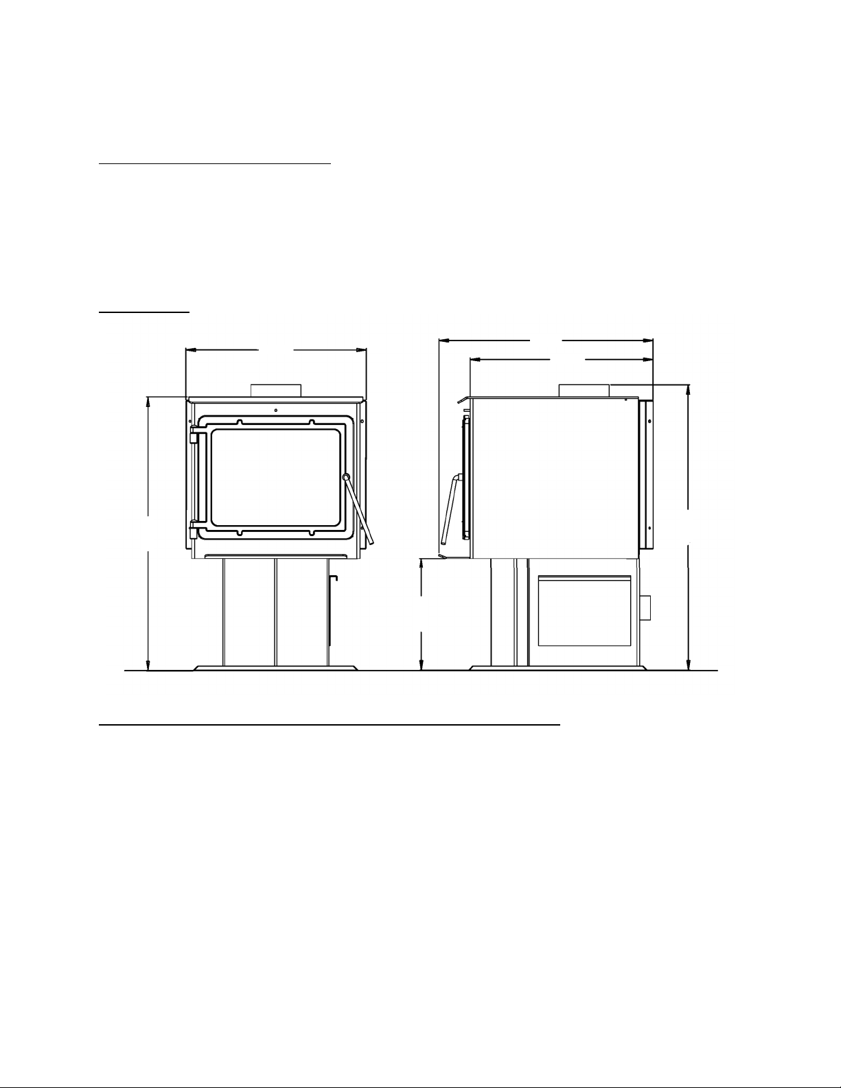
Page| 5
CARACTÉRISTIQUESTECHNIQUES
Caractéristiquesde chauffage
• Duréemaximaledecombustion**....................................................6à8heures
• Superficieapproximativechauffée***...................................... ...........185,81m²
• Capacitédelachambredecombustion........................................15,88kg(35lb)
• Buse.................................................... .........................................15,24cm,ronde
Dimensions(cm)
Conformitéauxnormes de sécurité etauxnormes de l’EPA
StatutdeconformitéEPA…….......Certifiéconformeauxnormesde2020surl’émissiondeparticuleslors
del’utilisationdegranulesdeboisparl’ENVIRONMENTALPROTECTIONAGENCYdesÉtats‐Unis.
NormedetestpourlesUSA:USEPA40CFRPart60,Subpart60.536
Tauxd’émission……………………………1.956grams/hr
Emissionsdemonoxydedecarbone………………………….1.659grams/min
Gammedeproduction dechaleur……………………..11,129–24,369Btu/hr
Efficacité…………………………………………73.77%(HHV)
TestépourEPA
Method28A,ASTME2780,ASTME2515,ULC/ORD‐C1482&ULCS627‐00
**–Laduréemaximaledecombustiondépendfortementdutypedeboisbrûlédanslepoêle;cesvaleurs
peuventdoncvarier.
***–Lacapacitémaximaledechauffagedecetappareilpeutvarierconsidérablementselonleclimat,letypede
construction,l’isolationetdenombreuxautresfacteurs.Combinezlesrenseignements
exposésdansleprésent
guideauxrésultatsd’uncalculdedéperditionthermiquepourvotremaisonafindedéterminersicetappareil
suffiraàcomblervosbesoins..
57,15
67,84
58,1
86,68
35,24
90,17

Page| 6
INSTALLATION
Vued’ensemble del’installation
Lorsquevouschoisissezl’emplacementdevotrenouveaupoêle,vousdevreztenir
compted’ungrandnombredefacteursavantdecommencerl’installation.
1.Habitudesdepassage–Afindeprévenirlesaccidents,lepoêledoitêtreinstalléàun
endroitoùiln’encombrepaslepassagehabitueldanslamaison.
2.Fluxdecha l eu r–Tenezcomptedelafaçondontlachaleurcirculedansvotremaisonpour
déciderdel’end roitoùvousinstallerezvotrepoêle.Installezlepoêleàl’endroitquevous
avezbesoindechau ff er.Souvent,uneinstallationensous‐solnepermetpasqu’une
chaleursuffisanteatteignelesétagessupérieurs,alorsqu’uneinstallationaudernier
étagenepermetpasquelachaleurserendeauxéta g esinférieurs.N’oubliezpasque,
tantqu’ilestchaud,l’airmonteetempruntelecheminoffrantlemoinsderésistance.
3.Emplacementdel’évacuation–Lemoteurd’unpoêleàboisestlesystèmedecheminée;
ilestdoncimportantd’examineravecprécisionlaméthoded’intégrationdusystèmede
cheminéelorsdel’installationdupoêle.Idéalement,lacheminéed’unpoêleàbois
devraitêtreenpositioncomplètementverticaleàpartirdelabusedel’appareiljusqu’à
l’extrémitéseterminantau‐dessusdelalignedetoiture.Unsystèmedecheminéesitué
complètementàl’intérieurdel’enveloppechaufféedelamaisonassurerauntiragefort
etfacileàamorcerdanslacheminée.Bienquelessystèmesdecheminéeextérieurs
fonctionnentsouventdefaçonadéquate,ilssubissentplussouventlecontre‐tiraged’air
froidàl’allumageousontfréquemmentlacaused’untiragefaibledel’appareil.Tenez
compteégalementdelasectiontransversaledelacheminée.Mêmesilescheminéesen
maçonnerieexistantespeuventsouventêtreutilisées,ilseradifficilevoireimpossiblede
fairefonctionnercorrectementl’appareilavecunegrandecheminéeenmaçonnerie
extérieure.Dansuntelcas ,ilserasouventnécessaired’utiliserunedoublurede
cheminéeisolanteafindefournirletiragenécessaire.
4.Constructiondumur–Lefaitdedisposerlepoêledesortequelesystèmed’évacuation
passeentreles montantsd’unecl oi sonsimplifiel’installationetéliminelanécessitéde
restructurerlessectionsdemuroudeplafondpouryposerlemanchon
d’emboîtementmuraloulaboîted’encastrementdeplafond.
AVERTISSEMENT
• Nestockezpasetn’utilisezpasd’essencenitouteautrevapeurouliquide
inflammableàproximitédecetappareiloudetoutautreappareil.
• Évitezl’emballementdupoêle.Sidespiècesextérieurescommencent
àrougeoyer,ilyaemballement.Réduisezl’alimentationenair.
L’emballementannuleravotregarantie.
• Respectez
lesindicationsrelativesauxdistancesminimalesaveclesmatières
combustibles.Lenon‐respectdecesexigencespourraitprovoquerl’incendie
delamaison.
• Testéetapprouvépourduboisenstéréseulement.L’utilisationdetout
autrecombustibleannuleravotregarantie.
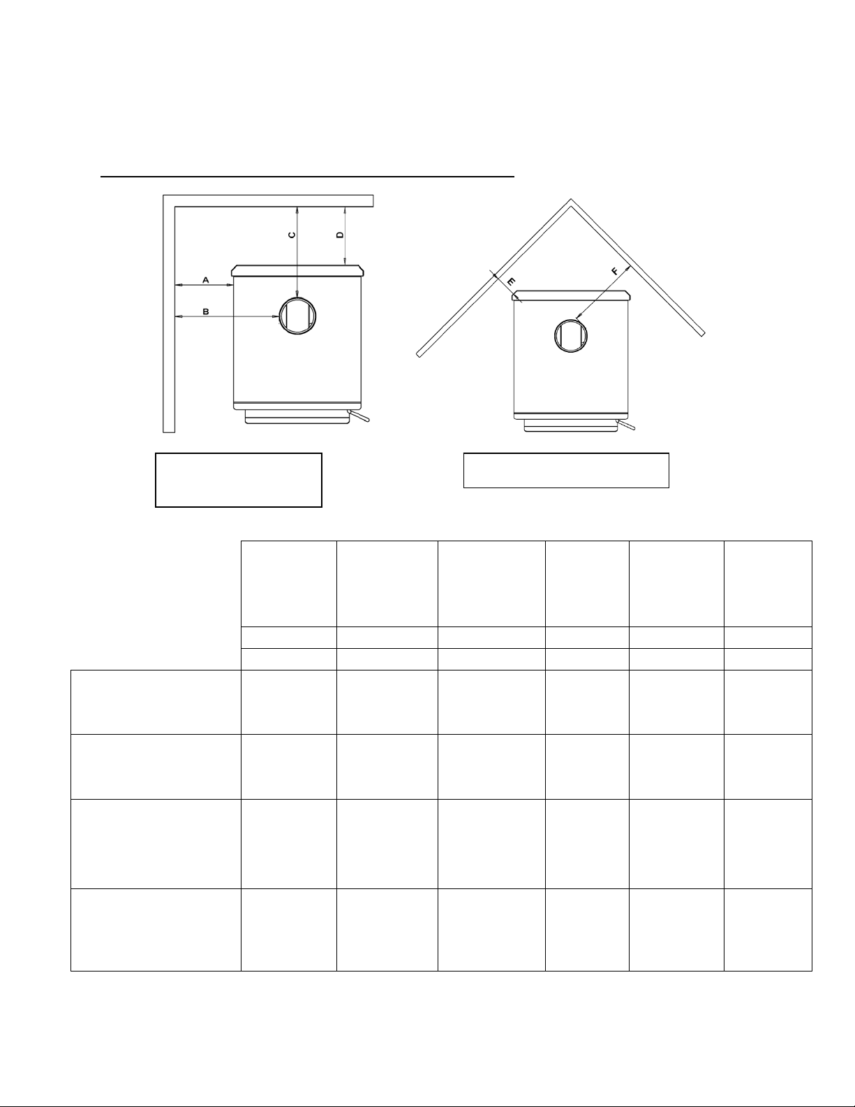
Page| 7
INSTALLATION
Distancesminimales avecles matièrescombustibles
Installation
parallèleaumur
Installationencoin
INSTALLEZL’ÉVENTENRESPECTANTLESDÉGAGEMENTSINDIQUÉSPARLEFABRICANTDEL’ÉVENT.
Del’appareil
aumur
latéral*
Duraccordde
cheminéeau
murlatéral
Duraccordde
cheminéeau
murarrière
Del’appareil
aumur
arrière
Del’appareil
aucoin
Duraccord
decheminée
aucoin
A B C D E F
mm(po) mm(po) mm(po) mm(po) mm(po) mm(po)
Raccorddecheminée
àparoisimplesurune
surfacenonprotégée
546,1
(21,5)
736,6
(29)
304,8
(12)
190,5
(7,5)
241,3
(9,5)
482,6
(19)
Raccorddecheminée
àparoidoublesurune
surfacenonprotégée
S.O.
S.O.
S.O.
S.O.
S.O.
S.O.
Raccorddecheminée
àparoisimplesurune
surfacenonprotégée
avecécranslatéraux
445,5
(17,5)
635
(25)
304,8
(12)
190,5
(7,5)
139,7
(5,5)
381
(15)
Raccorddecheminée
àparoidoublesurune
surfacenonprotégée
avecécranslatéraux
S.O.
S.O.
S.O.
S.O.
S.O.
S.O.

Page| 8
Généralités surlaventilation
INSTALLATION
Consignespourla ventilation
Cepoêleàboi sutiliseunsystèmede
tiragenatureldanslequellesystèmede
cheminéetirel’airdanslepoêle.Cetappareil
doitêtreinstalléconformémentauxtechniques
deventilationdécritesendétailci‐après.Le
non‐respectdesdétailsmentionnéspourrait
réduiresonrendementetcauserdes
dommagesmatériels,
desblessuresoulamort.
Évitezd’avoirrecoursàdesexpédients lorsde
l’installationdusystèmedeventilation.
England’sStoveWorksn’estpasresponsable
desdommagescausésparuneinstallation
incorrecteounonsécuritaire.
Assurez‐vousdebiensuivretoutesles
instructionsdufabricantrelativesausystème
deventilation,surtout
parrapportaux
distancesminimalesnécessairesavecles
matièrescombustibles.Assurez‐vous
égalementd’utiliserunécranantirayonnement
degrenierafin d’éviterquel’isolantentreen
contactavecunecheminéequitraverseun
grenier.
Lesystèmedecheminéeestle
«moteur»du poêleàbois.Ilestdo n c
essentielque
lesystèmedeventilationsoit
installéexactementselonladescription
indiquéedanslasectionsuivanteafind’assurer
unfonctionnementadéquatdel’appareil.
Pourtoutequestionrelativeà
l’installationsécuritairedupoêle,appelez
notreservicedesoutientechniqueau
1800245‐6489.Communiquezavecunagent
responsablelocalafinde
vousassurerque
l’installationestconformeauxexigences
municipalesetnationalesenmatièrede
préventiondesincendies.Sivousn’êtespas
certaindepouvoirinstallerlepoêledefaçon
sécuritaire,nousvoussuggéronsfortement
defaireappelàuninstallateurlocalcertifié
parleNFI(NationalFireplaceInstitutedes
États‐Unis).
• Installez TOUJOURSletuyaude
ventilationenrespectant
rigoureusementlesinstructionset
lesindicationssurlesdégagements
quiaccompagnentlesystèmede
ventilation.
• Ne raccordez PASlepoêleàboisàun
conduitdefuméedéjàutilisépourun
autreappareil.
• N’installez PASderegistredetirage,
niaucunautredispositif
deréglage
danslesystèmed’évacuationpar
ventilationdecetappareil.
• UTILISEZunmanchond’emboîtement
muralhomologuépourtraverserun
muretunsupportdeplafondouun
coupe‐feupourtraverserunplafond.
• INSTALLEZtroisvisàtôlesurchaque
jointderaccorddecheminée.
• ÉVITEZ
detropnombreuxcoudeset
parcourshorizontaux,carilsréduiront
letiragedusystèmedeventilation,ce
quinuiraaurendementdupoêle.
• INSPECTEZsouventlesystèmede
ventilationafindevousassurerqu’il
necontientpasdecréosote,de
cendresvolantesoud’autres
obstructions.
• NETTOYEZlesystèmede
ventilation
commeilestdécritdanslasection
surl’entretienduprésentguide.
• RESPECTEZlarègle10‐3‐2concernant
lesraccordementsdelacheminée.
• INSTALLEZleraccorddecheminée
àparoisimpleavecl’extrémitémâle
verslebaspouréviterlesfuitesde
créosote.Suivezlesinstructions
du
fabricantderaccordsdecheminéeà
paroidoubleconcernantl’installation
adéquatedestuyaux.
AVERTISSEMENT:LessurfacesdusystèmedeventilationdeviennentCHAUDES
etpeuventcauserdesbrûluressivouslestouchez.Ilpeutêtrenécessaire
d’utiliserunrevêtementoudesgrillesdeprotectionincombustibles.
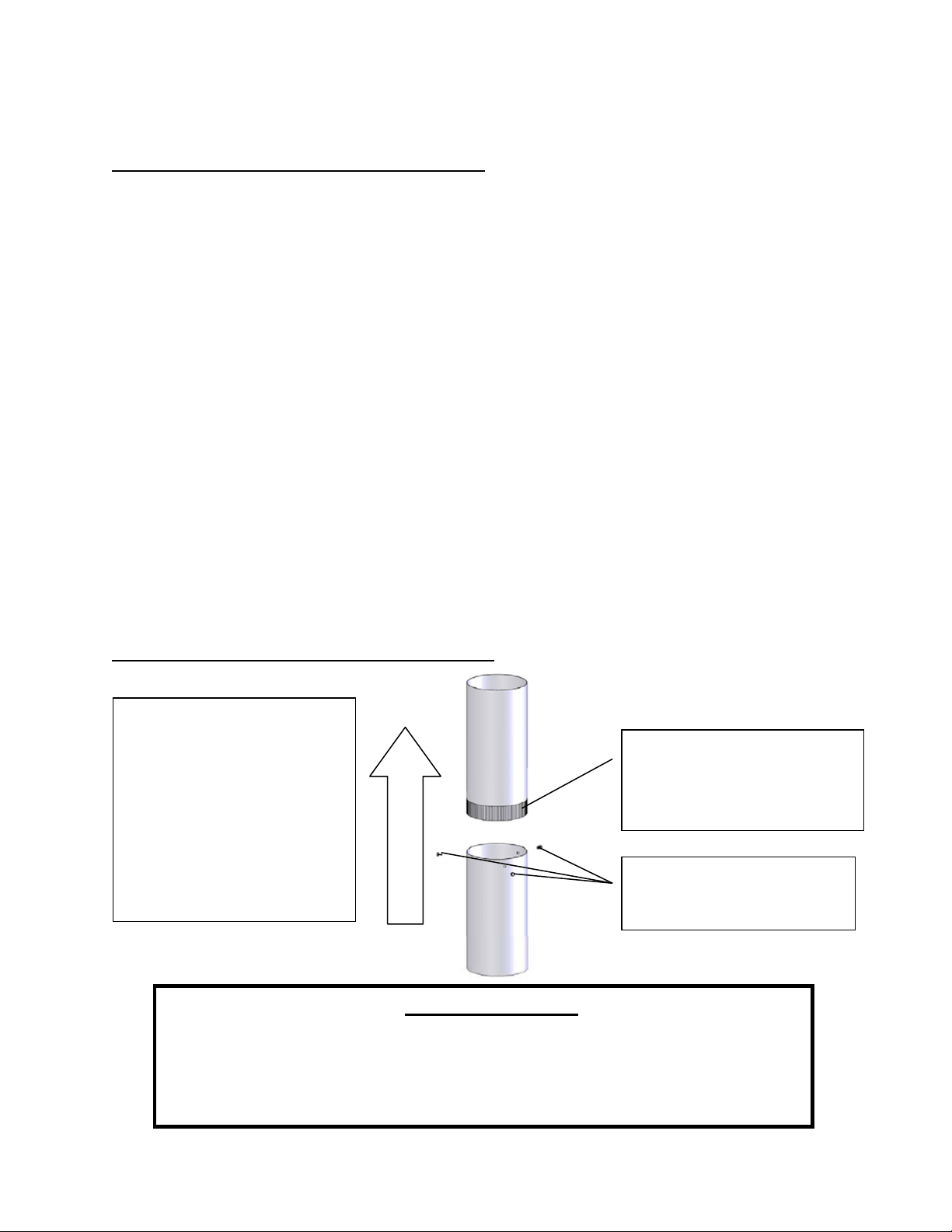
Page| 9
Directiondesgazdecombustion
INSTALLATION
Renseignements supplémentaires surlaventilation
• Ne mélangez pas et n’appariez pas de composants provenant de différents fabricants de
tuyauxlorsquevousinstallezlesystèmedeventilation(par exemple,n’utilisezPASuntuyau
deventilationd’unfabricantetunmanchond’emboîtementd’unautrefabricant).
• Nous exigeons une hauteur minimale de cheminée de 4,57m. Des systèmes de cheminée
pluscourtspourraientnepasassurerletiragenécessaireaufonctionnementadéquatdece
poêleàbois.
• N’ayezpasrecoursàdesexpédientslorsdel’installationdusystèmedeventilation.Faites
inspecterlesystèmedecheminéeexistantavantdel’utiliseretassurez‐vousquetout
nouveausystèmedecheminéeestinstalléselonlesspécificationsdufabricantetseulement
aveclescomposantshomologuésUL(ULCauCanada).
• Lessystèmesdeventilationpréfabriquésutiliséspourcepoêledoiventêtrehomologués
ULCS629(Canada)etUL103HT(États‐Unis).
• N’installezjamaisdesystèmedetirageparaspirationoutoutautresystèmequiaugmente
letiragenatureldelacheminée.Deplus,n’installezpasderegistrebarométriqueoude
registredetiragesurcetappareil.
• N’utilisezjamaisderaccorddecheminéeàparoisimpleoudoublecommesystèmede
cheminée.Nefaitesjamaispasserunraccorddecheminéedansunmurcombustiblesans
respecteràlalettrelesinstructionsdufabricantetcellesindiquéesàlapagesuivante
concernantlestraverséesdemur.Nefaites
JAMAISpasserunraccorddecheminéeàtravers
ungrenier,unplancher,unplacardouuntoit.
• Utilisezuniquementunraccorddecheminéenoiràparoisimpledecalibre24MSGouun
raccorddecheminéeàparoidoublehomologuéUL(ULCauCanada).
Installation d’unraccord decheminée àparoi simple
L’extrémitémâleduraccord
decheminéeàparoisimple
doitêtreorientéeverslebas
pourquelacréosoteliquide
danslabusepuisses’écouler
dansl’appareilplutôtqu’à
l’extérieurdutuyau(letirage
natureldanslesystèmede
cheminéeempêcheralafuite
defuméeparlesjoints).
L’extrémitésertieoumâledu
raccorddecheminéeàparoi
simpledoitêtreorientéevers
lebas.
Fixezchaquejointderaccord
decheminéeàparoisimple
àl’aidedetroisvisàtôle.
AVERTISSEMENT
• INSTALLEZL’ÉVENTENRESPECTANTLESDÉGAGEMENTSINDIQUÉSPARLE
FABRICANTDEL’ÉVENT.
• CHAUD!N’ytouchezpas!Celapourraitentraînerdegravesbrûluresou
l’inflammationdesvêtements.
• Lavitreetlesautressurfacessontchaudesdurantlefonctionnement.
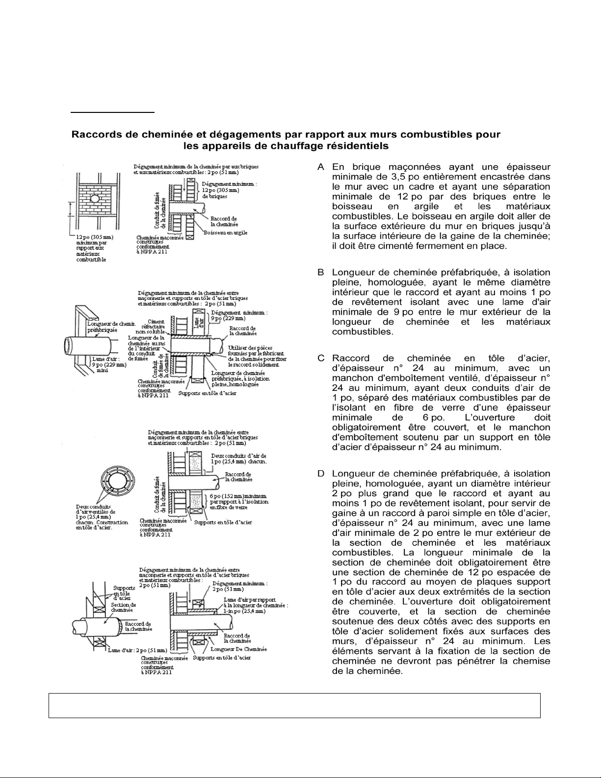
INSTALLATION
Traversées de mur
Au Canada, l’installation doit respecter la norme CAN/CSA‐8365 en cas de traversée de matériaux de construction
combustibles.
Page10
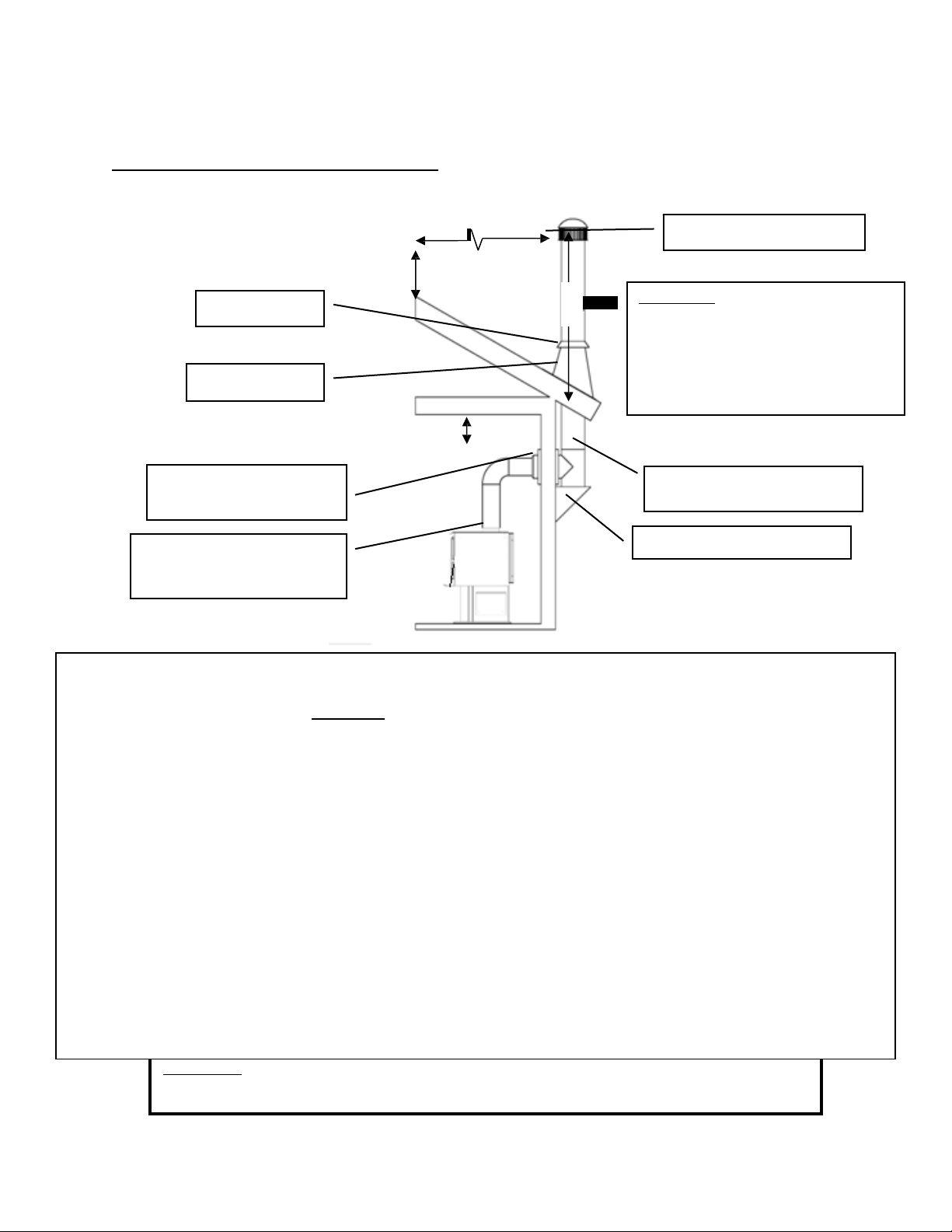
Page| 11
45,72c
0,61
0,91
INSTALLATION
Méthode deventilation approuvée 1:Àtraverslemuravecunecheminéepréfabriquée
3,05m
Capuchond’extrémité
Mitre
Solindetoit
Règle 10‐3‐2:Lesystèmedechemi née
doitseterminerà0,91mau‐dessusdu
pointoùsonaxecentral traverseletoi tET
lachem inéedoitsetermi nerà0,61m
au‐dessusdetoutepartiedulogement
dansunrayonde3,05 mdelacheminée.
Systèmedecheminée
declasseA
RaccordenTetsupport
• LessystèmesdecheminéepréfabriquésdoiventrespecterlesnormesULC‐S629(650°C)pourleCanada
etUL‐103HT(2100°F)pourlesÉtats‐Unis.
• Cepoêleàboisesthomologuéseulementpouruneinstallationavecunraccorddecheminéede15,24cmde
diamètreetunsystèmedecheminée.L’installationdecetappareilsurunecheminéepréfabriquéeayantun
diamètresupérieurà15,24cmdiminueraletirageetpourraitentraînerunrendementinsuffisantdel’appareil.
• Respe cteztouteslesexigencesdufabricantconcernantl’installationdusystèmedeventilationetlesdistances
minimalesnécessaires.
• Utiliseztroisvisàtôlepourchaquejointderaccorddecheminéeàparoisimple(vérifiezles
recommandationsdufabricantlorsdel’utilisationd’unraccorddecheminéeàparoidouble).
• Perceztroistrousdanslabusedel’appareiletfixezleraccorddecheminéeàl’appareil au moyende
visà
tôle(lestrousdevraientgénéralementêtreprépercésdanslabuseàl’usine).
• Fixezcorrectementlesystèmedecheminéepréfabriquéàlamaisonenrespectantprécisémentles
instructionsdufabricantdusystèmedecheminéepréfabriqué.
• Évitez de trop nombre ux coudes et pa rcours horizontaux, car ils réduiront le
tirage et entraîneront une
accumulation accrue de créosote. Les parcours horizontaux d’un raccord de cheminée ne doivent jamais
dépasser1,22metlalongueurtotaleduraccorddecheminéenedoitpasdépasser2,44m.
• Desadaptateursspéciauxetdesraccordsàglissementsontoffertspouréviterd’avoiràcouper
leraccordde
cheminée à paroi simple. Un raccord de cheminée à paroi double doit être utilisé avec ces raccords à
glissement,carilnepeutpasêtrecoupéenlongueur.
Veuillez noter:Lesschémasd’installationsontfournisàtitrederéférenceuniquementetnesontpasàl’échelle.Ilsnesontpas
destinésàêtreutiliséscommedesplansuniverselsd’installation.Veuillezrespectertouteslesexigencesrelativesausystèmede
ventilationetauxdistancesminimalesnécessairesaveclesmatièrescombustibles,etsuivretouslescodeslocaux.
Raccorddecheminée
(àparoisimpleoudouble)
Manchon
d
’
emboîte
ment
mural
45,72cm
0,91m
0,61m
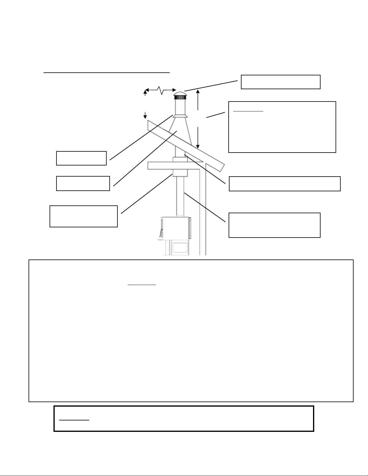
Page| 12
0,61m
0,91m
INSTALLATION
Méthode deventilation approuvée 2:Àtraversleplafond
3,05m
Capuchond’extrémité
Mitre
Règle 10‐3‐2:Lesystèmede chemi n ée
doitseterminerà0,91 mau‐dessusdu
pointoùsonaxecentraltraverseletoit
ETlacheminéedoitseterminerà0,61 m
au‐dessusde toutepartiedulogement
dansunrayonde3,05mdelacheminée.
Solindetoit SystèmedecheminéedeclasseA
Boîtedesupport
deplafond
Raccorddecheminée
(àparoisimpleoudouble)
• LessystèmesdecheminéepréfabriquésdoiventrespecterlesnormesULC‐S629(650°C)pourleCanadaet
UL‐103HT(2100°F)pourlesÉtats‐Unis.
• Cepoêleàboisesthomologuéseulementpouruneinstallationavecunraccorddecheminéede15,24cmde
diamètreetunsystèmedecheminée.L’installationdecetappareilsurunecheminéepréfabriquéeayantun
diamètresupérieurà15,24cmdiminueraletirageetpourraitentraînerunrendementinsuffisantdel’appareil.
• Respe cteztouteslesexigencesdufabricantconcernantl’installationdusystèmedeventilationetlesdistances
minimalesnécessaires.
• Utiliseztroisvisàtôlepourchaquejointderaccorddecheminéeàparoisimple(vérifiezles
recommandationsdufabricantlorsdel’utilisationd’unraccorddecheminéeàparoidouble).
• Perceztroistrousdanslabusedel’appareiletfixezleraccorddecheminéeàl’appareil au moyende
vis
àtôle(lestrousdevraientgénéralementêtreprépercésdanslabuseàl’usine).
• Fixezcorrectementlesystèmedecheminéepréfabriquéàlamaisonenrespectantprécisémentles
instructionsdufabricantdusystèmedecheminéepréfabriqué.
• Lalongueurtotaleduraccorddecheminéenedoitpasdépasser2,44
m.Danslecasd’unplafond
cathédrale,lesystèmedecheminéepréfabriquépeutdépasserde2,44màpartirdudessusdel’appareil.
• Desadaptateursspéciauxetdesraccordsàglissementsontoffertspouréviterd’avoiràcouperleraccordde
cheminéeàparoisimple.Unraccorddecheminéeà
paroidoubledoitêtreutiliséaveccesraccordsà
glissement,carilnepeutpasêtrecoupéenlongueur.
Veuillez noter:Lesschémasd’installationsontfournisàtitrederéférenceuniquementetnesontpasàl’échelle.Ilsnesontpas
destinésàêtreutiliséscommedesplansuniverselsd’installation.Veuillezrespectertouteslesexigencesrelativesausystèmede
ventilationetauxdistancesminimalesnécessairesaveclesmatièrescombustibles,etsuivretouslescodeslocaux.
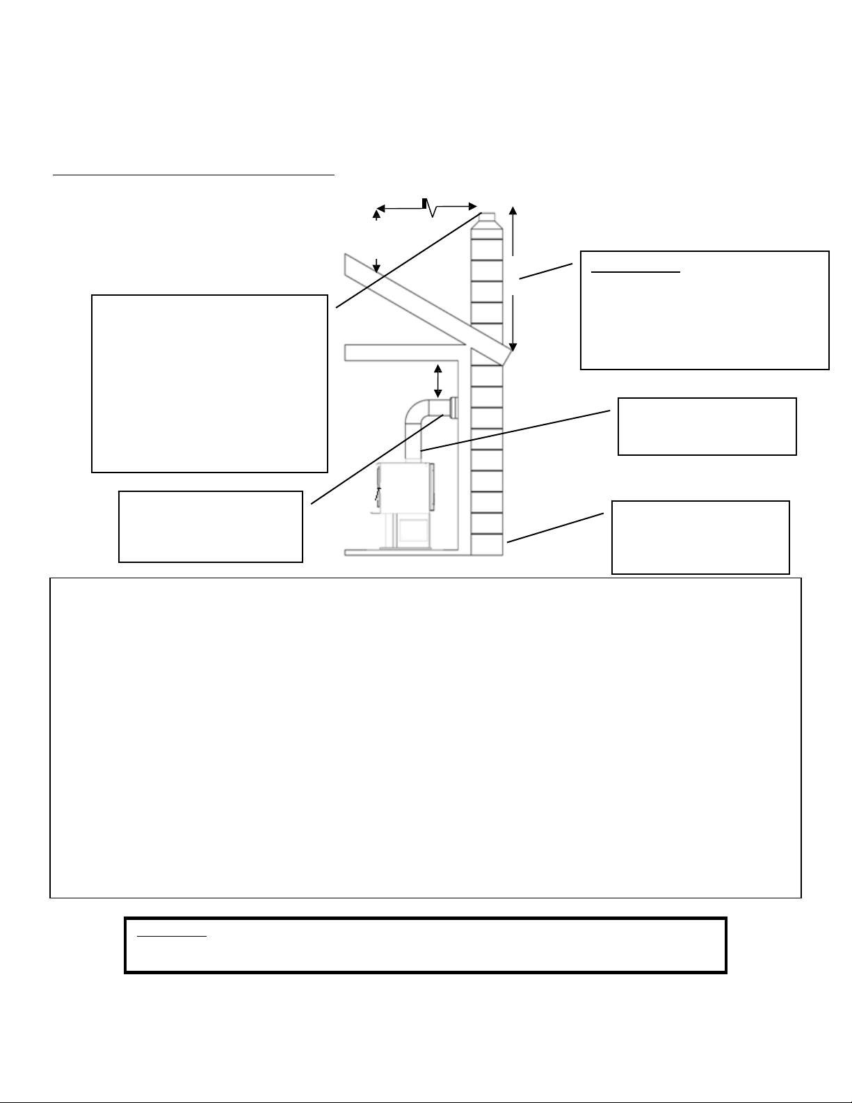
Page| 13
0,61m
45,72cm
0,91m
INSTALLATION
Méthode deventilation approuvée 3:Systèmedecheminéeenmaçonnerieintérieurouextérieur
3,05m
Règle10‐3‐2:Lesystèmede chemi n ée
doitseterminerà0,91 mau‐dessusdu
pointoùsonaxecentraltraverseletoit
ETlacheminéedoitseterminerà0,61 m
au‐dessusde toutepartiedulogement
dansunrayonde3,05mdelacheminée.
• Observezlesrèglesindiquéesci‐dessusconcernantladimensionmaximaleadmissibledeladoublurede
cheminée.L’installationdecetappareilsurunecheminéeenmaçonneriedontlasuperficiedelasection
transversaledépasse364,84
cm²diminueraletirageetpourraitentraînerunrendementinsuffisantdel’appareil.
• Utiliseztroisvisàtôlepourchaquejointderaccorddecheminéeàparoisimple(vérifiezles
recommandationsdufabricantlorsdel’utilisationd’unraccorddecheminéeàparoidouble).
• Perceztroistrousdanslabusedel’appareil
etfixezleraccorddecheminéeàl’appareilaumoyendevisà
tôle(lestrousdevraientgénéralementêtreprépercésdanslabuseàl’usine).
• Évitez de trop nombreux coudes et parcours horizontaux, car ils réduiront le tirage et entraîneront une
accumulation accrue de créosote. Les parcours horizontaux d’un
raccord de cheminée ne doivent jamais
dépasser1,22metlalongueurtotaleduraccorddecheminéenedoitpasdépasser2,44m.
• Unmanchond’emboîtementhermétiqueestessentielpourobtenirunrendementadéquatdel’appareilet
rendrel’installationsécuritaire.Utilisezunadaptateurdeconceptionadéquatepour relierleraccord
de
cheminéeàparoisimpleoudoubleaumanchond’emboîtementenma çonnerie.
• Avantd’utiliserl’appareil,faitesinspecterlacheminéeenmaçonnerieexistanteafindevousassurerqueson
utilisationestsécuritaireetquelesdistancesminimalesaveclesmatériauxcombustiblessontrespectées.Un
ramoneurcompétentpeuteffectuercetteinspection.
• Lescheminéesenmaçonnerieextérieuressubissentsouventlecontre‐tiraged’airfroidetontunfaibletirage
mêmesiellesrespectentlesrèglesdesuperficiedelasectiontransversale.Danscecas,ilpeutêtrenécessaire
d’utiliserunedoublureisoléede15,24cm.
Veuillez noter:Lesschémasd’installationsontfournisàtitrederéférenceuniquementetnesontpasàl’échelle.Ilsnesontpas
destinésàêtreutiliséscommedesplansuniverselsd’installation.Veuillezrespectertouteslesexigencesrelativesausystèmede
ventilationetauxdistancesminimalesnécessairesaveclesmatièrescombustibles,etobservertouslescodeslocaux.
Lasuperficie delasection
transversaledeladoublurede
cheminée(longueurxlarg eur)nedoit
pasdé passerdeplusdedeuxfoisla
superficiedelasectiontransv ersalede
labuse(2x182,39cm²=364,84cm²).
Siladoubluredechemi néedépasse
364,84cm²,vousdevezutiliserune
nouvelledoubluredecheminée
de13,97cmoude15,24cm.
Manchond’emboîtement
enmaço nnerie avec
dégagementadéqua taux
matièresc ombus ti bl es
Raccorddecheminée
(àparoi simpleoudouble)
Lespor tesdenettoyage
descen dresdoiventêtre
hermétiquespourévi ter
unfaibletirage.

Page| 14
INSTALLATION
INSTALLATION DANS UN FOYER EN MAÇONNERIE
Préparation
Mesurez l’âtre pour vous assurer qu’il est d’une largeur suffisante pour loger l’appareil.
L’appareil doit avoir un dégagement de 91,44cm entre la partie supérieure du poêle et le manteau
de cheminée selon la norme211 de la NFPA.
Pour les États-Unis: L’âtre doit dépasser d’au moins 406,4mm à l’avant de l’ouverture pour le
combustible.
Pour le Canada: L’âtre doit dépasser d’au moins 450mm à l’avant de l’ouverture pour le
combustible.
N’oubliez pas que ce type d’installation rend difficile le changement fréquent de vitesse du
ventilateur. Nous vous recommandons de choisir une vitesse de ventilateur et de maintenir
ce réglage, car il sera difficile de le modifier en raison de l’installation étroite.
AVERTISSEMENT: NE TENTEZ PAS DE RÉGLER LE VENTILATEUR DURANT LE
FONCTIONNEMENT. VOUS RISQUEZ DE SUBIR DES BRÛLURES LORS DU CONTACT
AVECL’APPAREIL. ATTENDEZ QUE L’ APPAREIL SOIT COMPLÈTEMENT REFROIDI AVANT
DERÉGLER LE VENTILATEUR.
Inspectez l’âtre pour vous assurer qu’il est fabriqué d’un matériau incombustible comme la brique ou
la pierre. N’installez pas ce poêle sur un âtre fabriqué d’une charpente en bois couverte de briques
ou de pierres et n
’installez pas cet appareil dans un foyer dont le dégagement est nul(0). Le
fabricant ne sera pas tenu responsable d’un accident causé par l’installation de ce poêle sur un âtre
fabriqué avec un matériau combustible.
Inspectez votre foyer pour vous assurer qu’il est en bon état de fonctionnement et qu’il est exempt
d’obstructions.
Avant l’installation, retirez le registre existant ou fixez-le à l’aide d’un câble pour le maintenir ouvert
de façon sécuritaire.
Ventilation du poêle– raccordement direct
Lorsque cet appareil est raccordé directement, un tuyau de calibre24 d’un diamètre de 15,24cm
doit être utilisé à partir du poêle jusqu’à l’ouverture du registre. (REMARQUE: Le raccord de
cheminée doit être fixé à l’appareil avec au moins trois (3) vis, et troisvis doivent être
utilisées pour fixer chaque section adjacente.)
Nous recommandons fortement l’utilisation d’une doublure de 15,24cm sur l’ensemble de la
cheminée pour assurer un tirage approprié. Il sera ainsi nécessaire d’obturer la zone ouverte des
deuxcôtés du tuyau traversant l’ouverture du registre au moyen d’une tôle ou d’un isolant en fibre
de verre à l’épreuve du feu dans les zones ouvertes (ni papier ni combustible). Vous devez vous
assurer que le tirage de la cheminée s’effectue par le poêle et non autour du tuyau de raccord.
Nous vous recommandons fortement que cette opération soit effectuée par un professionnel.
Communiquez également avec les autorités locales pour vous assurer que tous les codes sont
observés.
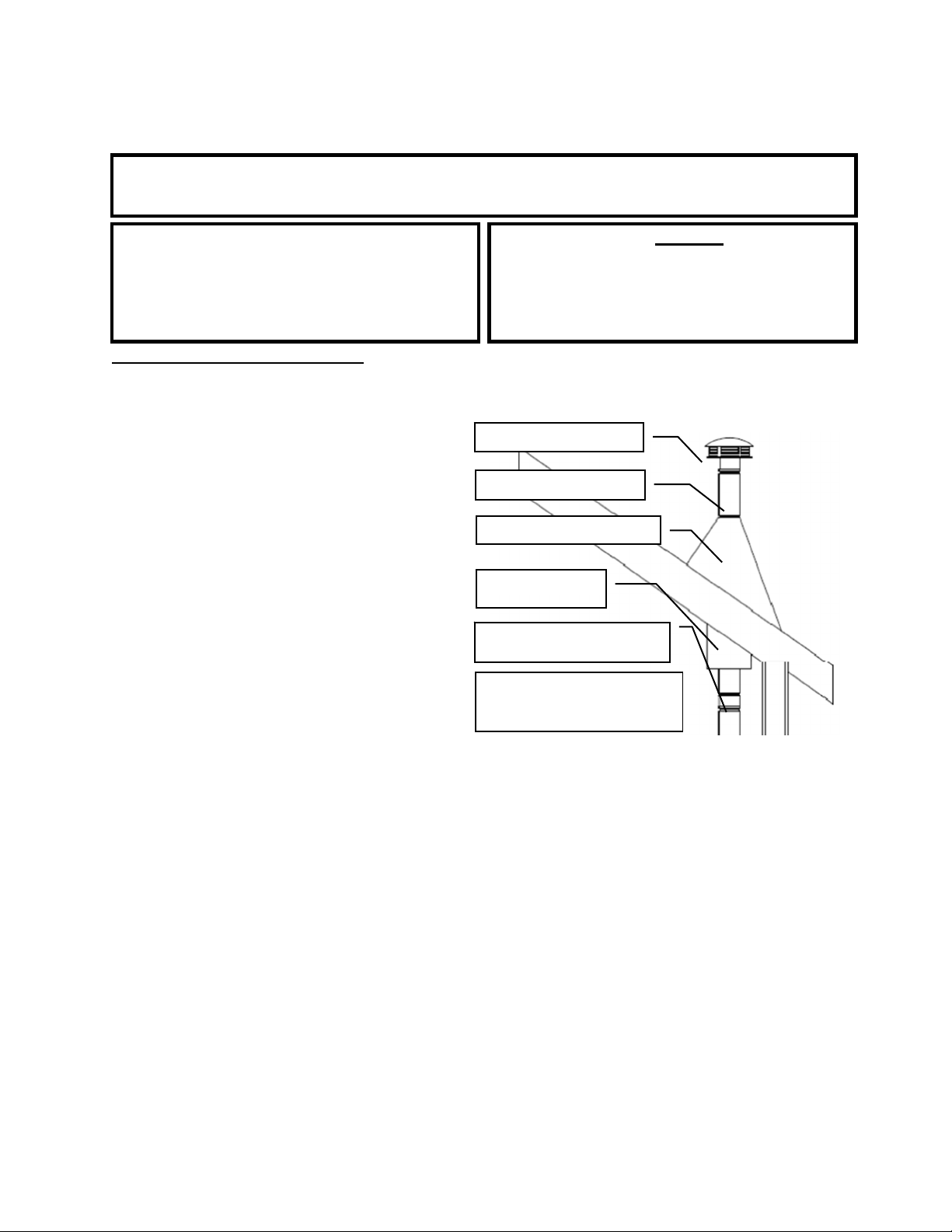
Page| 15
INSTALLATION
AVERTISSEMENT
N’INSTALLEZPASCETAPPAREILDANSUNECHAMBREÀCOUCHER.
ATTENTION
L’INTÉGRITÉSTRUCTURELLEDUPLANCHER,
DESMURS,DUPLAFONDETDUTOITDELA
MAISONPRÉFABRIQUÉEDOITÊTREPRÉSERVÉE.
Attention
NETIREZJAMAISl’aircomburantextérieur:
d’unecavitéd’unmur,d’unplancheroud’un
plafond,oud’unespacecloscommeun
grenier,ungarageouunvidesanitaire.
Installationdansune maison mobile(ÉTATS‐UNISSEULEMENT,NONAPPROUVÉEPOURUNE
INSTALLATIONDANSUNEMAISONMOBILEAUCANADA)
• LepoêleàboisDOITêtrefixéauplancher
delamaisonmobileàl’aidedetire‐fonds
disposésdanslestrousprévusàceteffet
danslapartieinférieuredel’appareil.
Utilisezunfildecuivren°8pourfixerle
poêleauchâssisdelamaisonmobile.
• Lepoêleàboisdoitêtreraccordéau
systèmedecheminéeàl’aided’unraccord
decheminéeàparoidoublehomologué UL
pourl’utilisationdansunemaisonmobile
oupréfabriquée.
• Observezattentivementtouteslesindications
relativesaudégagementmention néesàla
sectionappropriéeduprésentguideET
respectezlesexigencesdufabricantdu
systèmedeventilationconcernantles
distancesminimales.Deplus,assurez‐vous
quelesystèmedeventilationestapprouvé
pouruneutilisationdansunemaisonmobile.
• L’installationdoitêtreconformeàlanorme
ManufacturersHome&SafetyStandard(HUD)
CFR3280,partie24,desÉtats‐Unisainsi
qu’auxcodeslocauxenvigueur.
Chapeaudecheminéeet
pare‐étincelles
Systèmedecheminée
declasseA
Solindetoitetmitre
Protecteurdesolive
etcoupe‐feu
Raccorddecheminéeàparoidouble
approuvépour lesmaisonsmob iles
Utilisezdelasiliconepourcréer
uncoupe‐vapeuràl’endroitoù
lacheminéepasseàl’extérieur.

Page| 16
Air comburant extérieur
• L’utilisationdel’aircomburantextérieurestobligatoirelorsdel’installationdecepoêleàbois
dansunemaisonmobileoupréfabriquée.
• Letuyauderaccordementd’airextérieurdépassedelapartieinférieurecentraledupoêle;une
trousseestofferteparEngland’sStoveWorks,Inc.conçuepourra ccorder cetappareilàl’air
comburantextérieur.(N°depièceAC‐OAK3)
• S’iln’estpaspossibled’utiliserlatroussederaccordementd’airextérieurAC‐OAK3pour
l’installationdevotrepoêle,vouspouvezutiliserd’autresmatériauxàconditiond’observer
lesrèglessuivantes:
o Letuyauutilisépourleraccordementd’air extérieurdoitêtreenmétaletavoirune
épaisseurminimalede0,53mm.(acierdouxdecalibre25)etundiamètreintérieur
d’environ7cm.
o Conservezlalongueurdetuyaucourteetutilisezunefixationsurchaquejointdetuyau.
o Unécranouunautredispositifdeprotectiondoitêtreplacéaupointd’extrémitéd’air
extérieurafind’éviterquelapluie,lesdébrisoulesanimauxnuisiblesnepénètrentdansle
systèmedetuyauterie.Inspectezl’admissiond’aircomburantextérieurtouslesmoispour
éviterlesblocagesetl’accumulationdedébris.
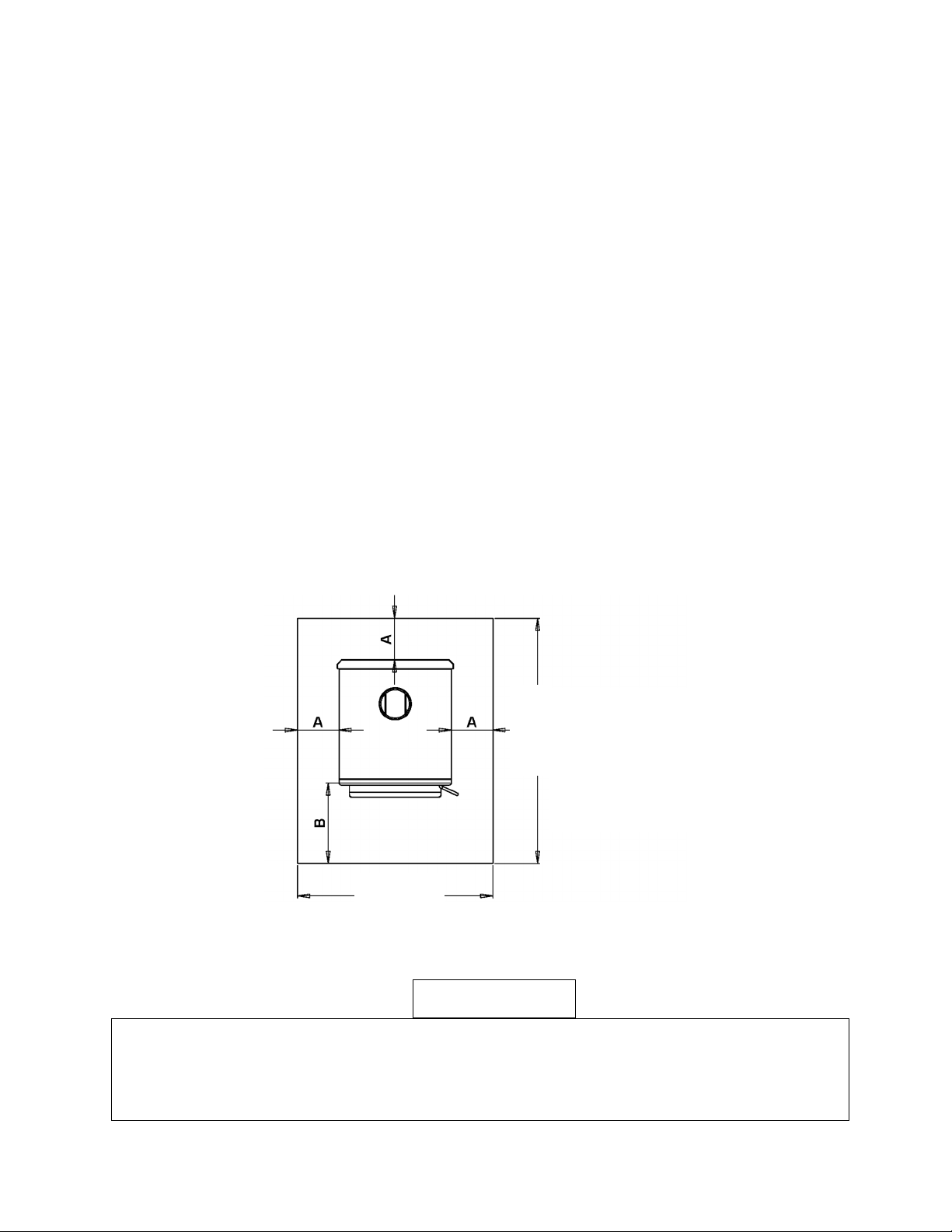
Page| 17
PROTECTIONDUPLANCHER
• Danslecasoùlepoêleàboisestinstallésurunplanchercombustible,ilestnécessaired’utiliserun
protecteurdeplanchercontrelesétincellesetlestisons conform eàlanormeULdetype1.Sile
planchersurlequellepoêledoitêtreinstalléestdéjàincombustible(par
exemple,leplancheren
bétond’unsous‐sol),aucunprotecteurdeplancher n’estrequis(vouspouveztoutefoisinstallerun
protecteurdeplancherdécoratif).
• Lorsquevousutilisezunprotecteurdeplanchercontrelesétincellesetlestisonsconformeà la
normeULdetype1,n’oubliezpasquelepoêleestnonseulementlourd,maisqu’ilimpose
égalementdesécartsdetempératureauprotecteurdeplancher,cequipeutendommagerles
carreauxetdétacher
lesjointsdemortieretdecoulissituésprèsdupoêle.
• LeprotecteurdeplanchercontrelesétincellesetlestisonsdoitêtrehomologuéULoul’équivalent
(ULCauCanada)etdoitêtreincombustible.Étantdonnéquelaplusgrandepartiedelachaleur
provenantdecetappareilestradiante,leprotecteurde planchersertuniquementàempêcherles
cendreset
lesétincellesdetombersurleplanchercombustibleprèsdel’appareil.Untapispour
âtren’estPASapprouvépourremplacerunprotecteurd’âtreapproprié.Aucunevaleurd’isolation
thermique«R»n’estnécessaire.
• PourlesÉtats‐Unis:Leprotecteurdeplancherdoitdépasserd’aumoins40,64cmàl’avantde
l’ouverturepourlecombustible,de20,32cmsurlescôtésdel’ou verturedeporteetde20,32cm
àl’arrièredel’appareil.
• PourleCanada:Leprotecteurdeplancherdoitdépasserd’aumoins450mmàl’avantdel’ouverture
pourlecombustible,de200mm surlescôtésdel’ouverturedeporteetde200mmàl’arrièrede
l’appareil.
• Leprotecteurdeplanchercontrelesétincelleset lestisonsdoitdépasserde50,8mm(2po)dechaque
côtédesparcoursdeventilationhorizontauxetdirectementsousuntuyaudeventilationvertical.
ATTENTION
N’UTILISEZJAMAISD’ESSENCE,DECOMBUSTIBLEPOURLAMPEAPPARENTÉÀL’ESSENCE,DE
KÉROSÈNE,DELIQUIDED’ALLUMAGEPOURCHARBON,NIAUCUNLIQUIDESIMILAIREPOUR
ALLUMEROURAVIVERUNFEUDANSCETAPPAREILDECHAUFFAGE.CONSERVEZDETELS LIQ U IDES
ÉLOIGNÉSDEL’APPAREILDEC H AUFFAGELORSQUECELUI‐CIFONCTIONNE.DEPLUS,NEDISPOSEZ
JAMAISD’ALLUME‐FEUXSURUNESURFACECHAUDENISURDESTISONSDANSLEPOÊLE.
97,79cm
119,38cm
A:É.‐U.8po
CA200mm/8po
B:É.‐U.16po
CA450mm/16po

Page| 18
UTILISATION
Premiers feux
• Cepoêleàbois,conçupourdurerlongtemps,estfabriquéenacierépaisetenfonte.Cependant,
pouréviterqu’unetensionthermiqueexcessivesoitinduiteaumétalpendantlepremierfeu,ilfaut
troispetitsfeuxderodage,ens’assurantquechaquefeusoitlégèrementpluschaudquele
précédent.Cesfeuxderodageneservirontpasseulementàacclimaterlepoêleauxtempératures
élevées,maisilsaiderontaussiàfairedurcirlentementlapeinturepourpoêlerésistantauxhautes
températures,cequipermettraaufinidequalitésupérieurededurerplusieursannées.N'oubliez
pasd'ouvriruneporteet/
ouunefenêtrepourventilerlazone.
• Cepoêleestmunid’uneseuletigedecommanded’airquirégulariseletauxdecombustiondubois.
Lorsqueledispositifcoulissantdecommanded’airprimaireesttirécomplètementversl’extérieurde
l’appareil,lepoêlechauffepluslentementetfournitdela
chaleurpluslongtemps.Àl’inverse,
lorsqueledispositifcoulissantdecommanded’airestenfoncécomplètementversl’intérieur,
l’appareilchauffeplusviteetfournitunechaleurplusintensesurunepérioderelativementplus
courte.N’essayezpasdemodifierleréglagedecommanded’airpeuimportelaraison.
• Lepremierfeu
derodagedevr aitêtreungrandfeudeboisd’allumagepermettantaupoêled’atteindre
unetempératurede148,9°Cmesuréeparunthermomètre magnétiqueducôtégaucheoudroitdu
poêle,au‐dessusdelapo r te .Unefoiscettetempératureatteinte,laissezlefeus’éteindreengardantla
commanded’air
ouverte.Lesdeuxièmeettroisièmefeuxderodagedevraien têtreunpeuplusimportants
enajoutantquelq uespetitsmorceauxsecsauboisd’allumage.Latempératureàatteindrepend ant ces
feuxsesitueentre176,7°Cet232,2°Cenviron;nelaissezpaslefeudépasse r cettetempérature.
Utilisation continuelle
• Une fois les premiers feux de rodage terminés, cet appareil est prêt pour une utilisation continuelle.
Lorsque lepoêle fonctionne continuellement, ne laissez pas lacendre et les braises s’accumulerplus
haut que le trou d’air dans le boîtier decrampon. Une quantité excessive de braises signifie souvent
qu’une
tropgrandequantitédeboisbrûleàuntauxdecombustiontropélevéetvousdevriezlaisserle
litdebraisesbrûleravantd’ajouterunenouvellechargedeboisaupoêle.
• L’aircomburantentredanslepoêlepardeuxendroits:Lamajoritédel’aircomburantprimaireentre
dans
lachambredecombustionparlesystèmeautonettoyantquigardelavitrepropreetalimenteles
flammesdecombustionprimairessurlessurfacessupérieuresdubois.Unepartiedel’aircomburant
primaireestacheminéedanslelitdebraisesparletroudecramponsituédansleboîtieravant
inférieurdu
poêle.(L’airestacheminéàpartirdudessousdel’appareil.)Tousleseffortspossibles
doiventêtredéployéspourconserverlazoneàl’avantdecetroulibredecendres.
• Lorsduremplissagedupoêlepouruneflambéedelonguedurée,ilesttrèsutiledefaireun«V
»au
centredulitdebraisespourpermettreautroudepurged’airprimairedepousserl’aircomplètement
àl’arrièredel’appareil.
• Aprèsavoirremplicomplètementlachambredecombustiondupoêleavecunenouvellechargede
bois,ilestimportantdefairefonctionnerl’appareilaveclacommande
d’airenpositiond’ouverture
complèteafindecarboniseradéquatementlachargedeboisetd’évacuerl’humiditéinitialecontenue
danslanouvellecharge.Unefoisleboisbiencarboniséetallumécomplètement,lacommanded’air
peutêtrerégléepourobtenirleniveaudechaleursouhaité.
• Cetappareilestmuniégalement
d’unenouvellecaractéristique.Lorsduremplissagedupoêlepour
uneflambéelentedelonguedurée,vouspouvezréglerleregistredecommanded’airpourpermettre
lechauffagedel’appareiletunebonnecombustionavantdefermerlacommanded’airenposition
faible.Tirezsimplementversl’extérieurlatigeenposition
basseettournez‐ladanslesensdesaiguilles
d’unemontrejusqu’àcequevousentendiezunlégerdéclic(environunquartdetour).Leregistrese
fermeautomatiquemententempsopportun.Cecis’appliquepourlesréglagesenpositionfaibleet
moyennementfaible.
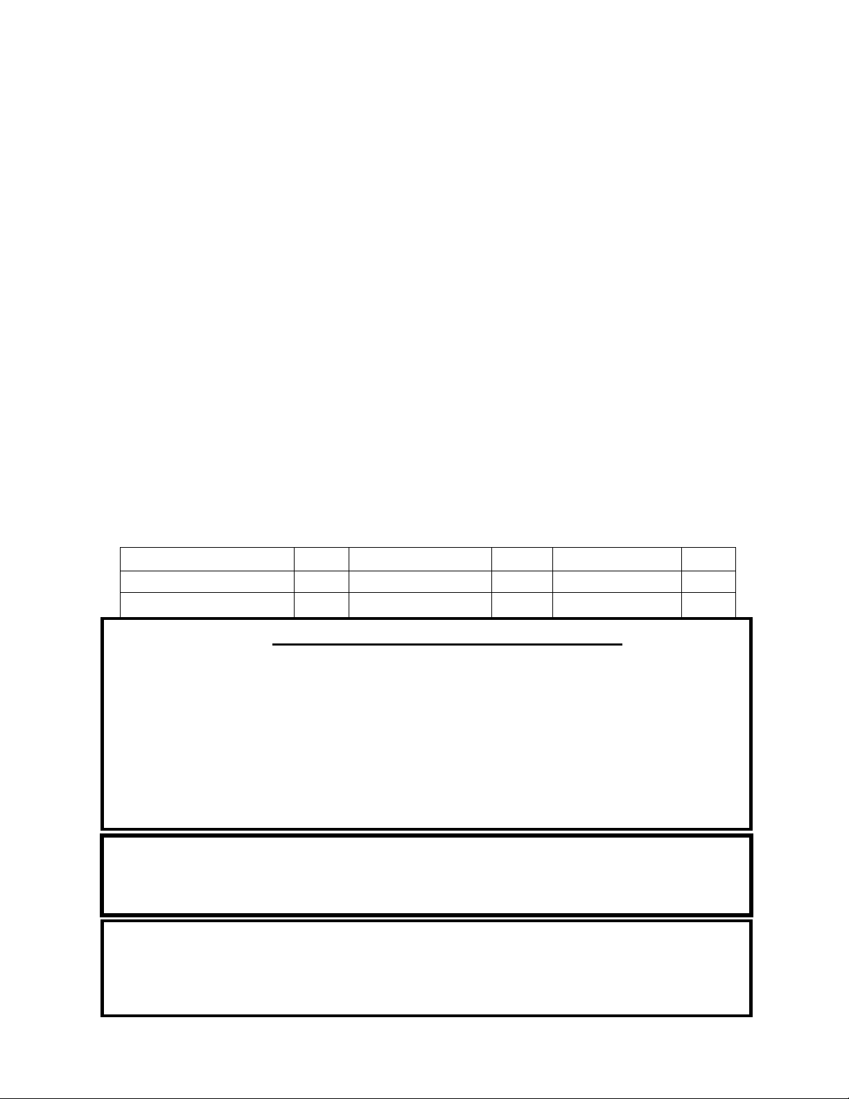
Page| 19
UTILISATION
• England’sStoveWorks,Inc.recommandetoujoursl’utilisationd’unthermomètredepoêle
magnétiqueafindesurveillerlatempératuredel’appareil.Lorsdel’utilisationd’unthermomètre
depoêlemagnétique,installez‐leau‐dessusdelaporteducôtégaucheoudroitdupoêleet
utilisezlestempératur essuivantescommeguidepourdéterminer
letauxdecombustionetle
degrédechaleurémiseparlepoêle:
o Lefonctionnementnormaldupoêleàboissesitueentre176,7°C(350°F)et287,8°C
(550°F).De176,7°C(350°F)à232,2°C(450°F),ledegrédechaleurseradefaible
à
moyenetde232,2°C(450°F)à287,8°C(550°F),ledegrédechaleurserademoyen
àélevé.Lefonctionnementdupoêleà315,6°C(600°F)seraitlatempératuremaximale
admissiblepouruneutilisationcontinue.L’utilisationdupoêleàcettetempératureavec
untauxde
combustionélevépourdelongues périodespourraitl’endommager.Le
fonctionnementdel’appareilàunetempératureégaleousupérieureà343,3°C(650°F)
estconsidérécommeunemballementetendommageral’appareil.
• Leventilateurdeconvectiondel’airenoptionaétéconçupourextraireunmaximumdechaleur
dupoêleafind’obtenirlemeilleurtransfertdechaleurpossibledanslapièce.Étantdonnéque
leventilateurestsiefficaceàretirerdelachaleurdel’appareil,ilesttrèsimportantde
lefaire
fonctionnerseulementaprèsqu’unenouvellechargedeboisaeuletempsdebrûlerpendant
aumoins30minutes.Lefaitdelaisseràunenouvellechargedeboisletempsdebrûleravant
d’utiliserleventilateurpermetàl’appareild’atteindreunetempératuredefonctionnement
adéquateetpermet
ausystèmedecombustionsecondairedefonctionnercorrectement.
Suivezégalementlesdirectivesci‐dessouspourconnaîtrelesvitessesappropriéesduventilateur.
• Lorsquevousutilisezleventilateurdeconvectiondel’airenoption(n°depièceAC‐16oula
nouvelleversionAC‐30),celui‐cidoitfonctionnercommesuit,selonledegrédechaleur:
Tauxdecombustion Élevé Moyennementélevé Moyen Moyennementbas Bas
VitesseduventilateurAC‐16 Élevée Élevée Basse Basse Basse
VitesseduventilateurAC‐30 Élevée Moyennementélevée Moyenne Moyennementbasse Basse
Créosote – Formation et importance du retrait
Lorsqueleboisbrûlelentement,ilproduitdugoudronetd’autresvapeurs
organiquesquisecombinentàl’humiditéévacuéepourformerlacréosote.Les
vapeursdecréosotesecondensentdansleconduitdefuméerelativementfroid
lorsquelefeuseconsumelentement.Parconséquent,desrésidusdecréosote
s’accumulentsurle
conduitdefumée.Lorsqu’elles’enflamme,cettecréosote
produitunfeuextrêmementchaud.Lacheminéeetleraccorddecheminéedoivent
êtreinspectésaumoinstouslesdeuxmoispendantlasaisondechauffageafinde
vérifiersiuneaccumulationdecréosotes’estproduite.Encasd’accumulationde
créosote,celle‐ci
doitêtreretiréeafinderéduirelerisquedefeudanslacheminée.
VOUSNEDEVEZPASUTILISERDEGRILLENISURÉLEVERLEFEU–INSTALLEZLEBOIS
DIRECTEMENTSURL’ÂTRE
N’UTILISEZPASL’APPAREILAVECLAPORTEPRINCIPALEOUVERTE–VOUSRISQUERIEZ DE
PROVOQUERUNEMBALLEMENT
Encasdefeucauséparuneaccumulationdecréosoteoudesuie(feudecheminée),fermezla
commanded’airsituéesurlepoêle,communiquezavecleserviced’incendielocaletquittezles
lieux!Neversezpasd’eausurlefeu!Communiquezavecleserviced’incendielocalpourobtenir
deplus
amplesrenseignementssurlaprocédureàsuivreetsurlaméthodeàutiliserrelativeà
unpland’évacuationsécuritairepourvousetvotrefamilledanslecasd’unfeudecheminée.

Page| 20
FONCTIONNEMENT
Consignes desécurité supplémentaires
MISEENGARDE:Lorsquevousajoutezducombustibleaupoêle,leventilateurdoitêtreéteint.
• L’installationdedétecteursdefuméeestfortementrecommandéelorsquevousinstallezcet
appareiloutoutautretyped’appareilàcombustiblesolide.Lesdétecteursdefuméedoivent
êtreinstallésprèsdechaquepiècedelamaison,voiredanscelles‐ci,plusparticulièrement
pourleschambresàcoucher.
• Undétecteurdefuméepeutêtreinstallédanslamêmepiècequelepoêleàboisenstéré.
Toutefois,s’ilesttropprèsdel’appareil,ilpourraitémettredefaussesalarmesàcausedesfilets
defuméequipeuvents’échapperàl’allumage dufeuoupendantleprocessusderechargement.
Pour
cetteraison,ledétecteurdefuméeinstallédanslamêmepiècequel’appareildevraitêtre
placéaussiloindel’appareilquelapiècelepermet.
• Cepoêleestuniquementconçupourbrûlerduboisnaturel.Lacombustiond’unboisdurséché
àl’air,plutôtqu’unboisrésineuxouunboisdurfraîchementcoupé,accroîtlerendementdupoêle
enplusderéduirelesémissionsauminimum.NEFAITESPASBRÛLERdesdéchets,dugazoncoupé
oudesrésidusdejardinage,desmatériauxcontenantducaoutchouc,ycomprisdespneus,
desmatériauxcontenantduplastique,desdéchetsdeproduitspétroliers,delapeintureoudu
diluantàpeinture,desproduitsbitumineux,desmatériauxcontenantdel’amiante, desdéblais
oudesdébrisdeconstruction,destraversesde
chemindeferou duboistraitésouspression,
dufumieroudesrestesd’animaux,duboisdegrèveimprégnéd’eausaléeoudesmatériaux
préalablementsaturéseneau salée,desproduitsdepapier,ducarton,ducontreplaquéoudes
panneauxdeparticules.L’interdictiondebrûlercesmatériauxnevousempêche
pasd’utiliser
desallume‐feuàbasedepapier,decarton,desciure,decireoud’autressubstancessemblables
pourallumerunfeudanslepoêleàbois.Lacombustiondecesmatériauxpeutcompromettre
l’efficacitédupoêleetproduiredelafuméeetdesvapeurstoxiques.
• Lefaitdebrûlerd’autrescombustiblesqueleboisenstéré,plusparticulièrementducharbon
etducharbondebois,peutentraînerdesémanationsàfortesconcentrationsenmonoxyde
decarbonedansl’habitation.Pourcesraisons,nefaitesJAMAISbrûlerducharbonnidu
charbondeboisdanscepoêleà
boisenstéré.L’installationd’undétecteurdemonoxydede
carboneetlaconnaissancedessymptômesd’unempoisonnementaumonoxydedecarbone
peuventréduirelesrisquesliésaumonoxydedecarbone.
• Cetappareilestconçupourfonctionneruniquementlorsquelaportedechargementestfermée
etbienverrouillée.Lefonctionnementdecetappareilaveclaportedechargementouverteou
malverrouilléeentraîneral’acheminementverslefeud’unequantitéexcessived’aircomburant,
cequiferaaugmenterdangereusementlatempératuredel’appar eil.
Unetempératureélevée
peutendommagerl’appareil,entraînerl’annulationdelagarantieetenflammerlacréosote
accumuléedanslesystèmedecheminéedurantlesfeuxàcombustionlenteprécédents.
• Letiragenaturelquitirel’airdansl’appareiletpermetaufeudebrûlerutilisel’airinté rieurdu
logementpourassurerlacombustion,àmoinsquel’appareilnesoitraccordéàunesourced’air
comburantextérieur.Leshottesàévacuationdec ui sin iè re,lesfournaisesetlesau tr e sapparei ls de
circulation
d’airdanslamaisonretirentaussidel’airdulogement.Silaquantitéd’airfiltréoud’air
entrantdanslamaisonestinférieureàcelleretirée delamaison,unepressionnégativepeu tse
produire.
N’ENTREPOSEZPASDECOMBUSTIBLESPLUSPRÈSQUELESDÉGAGEMENTSSPÉCIFIÉSOU
DANSL’ESPACENÉCESSAIREAUCHARGEMENTDUPOÊLEETAURETRAITDESCENDRES.

Page| 21
• Étantdonnéquecetappareilfonctionneavecuntiragenaturel,ceserasouventle premierappareil
touchéparunepressionnégative.Sidelafuméeestex pu l séehorsdesjointsderaccordde
cheminéeoudusystèmed’inductiond’airdel’appareil, c’estprobablementparcequelepoêle
combatlapression
négativedulogement.L’ouverturepartielled’une fenêtreoud’uneporteprès
del’appareilpeutaideràégali se rlapression.Finalement,ilpourraitêtre nécessaired’ajouterune
sourced’aircomburantexté rieur dégagéepourassurerlefonctionnementadéquatdel’appareil.
• Sil’appareilestraccordéàl’airextérieur,assurez‐vousdesurveillerlesaccumulationsdeglace
oudeneigepouvantbloquerl’entréed’airextérieurdusystèmedecombustion.Pouréviterun
manqued’airpourl’appareil,leraccordd’airextérieurnedoitpasêtreobstrué.
Pratiquesdechauffageauboissécuritaires
Unefoisquevotreappareildechauffageauboisestcorrectementinstallé,suivez
cesdirectivespourassurerunfonctionnementsécuritaire:
• Teneztouslesarticlesdemaisoninflammables(draps,meubles,journauxet
livres)loindel’appareil.
Pourallumerunfeu,utilisezuniquementdupapierjournal,duboisd’allumageet
unallume‐feuentièrementnatureloubiologique.N’utilisezjamaisd’essence,de
kérosèneoud’allumoiràcharbonpourallumerunfeu.
Nebrûlezpas
debûcheshumidesouvertes(nonséchées).
N’utilisezpasdebûchesfaitesdecireoudesciuredeboisdansvotrepoêleàbois,car
ellessontconçuespourdesfoyersouverts.Sivousutilisezdesbûchesfabriquées,
prenezcellesquisontfaitesdesciuredeboiscompresséeà100
%.
Faitesdesfeuxchauds.Pourlaplupartdesappareilsdechauffageaubois,unfeuqui
couven’estnisécuritaireniefficace.
Gardezferméeslesportesdevotreappareildechauffageauboissaufpourajouterdes
bûchesoualimenterlefeu.Desproduitschimiquesnocifs,commele
monoxydede
carbone,peuventêtrelibérésdansvotredomicile.
Retirezrégulièrementlescendresdevotreappareildechauffageauboisdansunrécipient
enmétaldoté d’uncouvercle.Rangezlerécipientcontenantlescendresàl’extérieur,sur
unedalledecimentoudebrique(etnonpassuruneterrasseenboisniàproximitéde
bois).Consultezlesinstructionssurleretraitdescendresdansleguided’utilisation.
Gardezunextincteurd’incendieàportéedelamain.
N’oubliezpasdeconsulterlesprévisionslocalessurlaqualitédel’airavantd’utiliser
votrepoêleàbois.

Page| 22
ENTRETIEN
Entretien quotidien
• Vérifiezl’accumulationdecendresdanslachambredecombustion.Retirezl’excèsde
cendresetsuivezlesinstructionsindiquéesci‐dessousconcernantl’éliminationdes
cendres.Lescendresnedevraientpass’accumulerdanslepoêleaupointdecouvrir
letrouduboîtierdecrampon.
Entretien mensuel
• Vérifiezlaprésenced’uneaccumulationdepoussièredansleventilateur(s’ilestinstallé).
Vérifiezlebonfonctionnementdelapoignéedeporteetassurez‐vousquelaportese
fermehermétiquement.
• Inspectezlesystèmedecheminéeetleraccorddecheminée,puiseffectuezleramonage
aubesoin.Mêmesi
lenettoyagen’estpasnécessairetouslesmois,inspectezTOUJOURS
lesystèmed’évacuationchaquemoispourréduirelapossibilitéd’unfeudecheminée.
• Faitesuneinspectionvisuelledespanneauxd’isolationenfibresdecéramiquedela
chambredecombustionpourvérifierlaprésencedefissuresoudebris.Des
fissures
superficielleslégèresnenuirontpasaurendementdespanneaux,maisdespanneaux
fissurésoueffritésdoiventêtreremplacésimmédiatement.
• Faitesuneinspectionvisuelledestubesdecombustionsecondairespourvousassurer
qu’ilsnesontpasfissurés,déformésoucorrodés.Mêmesicestubessontfabriquésen
acierinoxydable,ils
fonctionnentàdestempératurestrèsélevéesetpeuventfinirpar
s’userlorsd’uneutilisationnormale.
Entretien annuel
• Vérifiezlaprésenced’usuresurtouslesjointsd’étanchéité(fenêtreetporte)etassurez‐
vousqu’ilscontinuentdefournirunefermeturehermétique.Consultezlapagesuivante
pourlesinstructions.
• Nettoyezàfondlesystèmedecheminéeetlesystèmederaccorddecheminée.Étantdonné
queleraccordde
cheminéeestgénéralementsoumisàdestempératuresd’évacuation
élevées,vérifiezlaprésencedefuitesetdepointsfaibles,puisremplacezlespiècesdont
l’étatestdouteux.(Danslecasd’unsystèmedecheminéecomplètementdroitjusqu’autoit,
assurez‐vousderetirerlesdéflecteursenfibresdecéramiqueavantdepousser
labrosse
deramonagedanslachambredecombustion.Lefaitdefrapperavecforcesurlapartie
supérieuredudéflecteuravecunebrosseouunetigedenettoyagepeutendommagerle
déflecteurouledétruire.)
• Retireztoutelacendreaccumuléedanslepoêleycompriscelleaccumuléesurla
partie
supérieuredesdéflecteursdelachambredecombustion.Laissezlerégulateur
d’admissiond’airouvertpendantlesmoissanschauffagepourpermettreunecirculation
d’airdanslepoêleafind’aideràprévenirlacorrosion.Unpetitcontenantouvertrempli
delitièrepourchatplacédanslepoêlepeutaiderà
prévenirlacorrosionpendantles
moishumidesdel’été.Pensezàretirerlecontenantavantdefaireunfeuàl’automne.
L’ENTRETIENINADÉQUATDESJOINTS,YCOMPRISLENON‐REMPLACEMENTDESJOINTS,
PEUTENTRAÎNERDESFUITESD’AIRCAUSANTUNFEUNONMAÎTRISÉDANSL’APPAREIL.
Éliminationdescendre s–Lescendresdoiventêtre placéesdan suncontenantmétalliqueavecun
couverclehermétique.Lecontenantferméremplidecendresdoitêtreplacésurunplancher
incombustibleousurlesol,loindetouslesmatériauxcombustibles,enattend antl’éliminati onfinale.
Sivousvousdébarrassezdescendresen
lesenterrantouenlesdispersant,vousdevezd’abordles
conserverdansuncontenantfe rméjusqu ’àcequetoutesle scendressoientcomplètementrefroidie s.

Page| 23
Inspection desjointsd’étanchéité
ENTRETIEN
Ilestessentielquelejointdel’ouverturedeportesoitétancheàl’airpourassurerle
rendementadéquatdupoêle.Toutefuited’airdanscettezonepeutentraînerunemballement
etdoncunrisquegravepourlasécurité.Pourcetteraison,vousdeveztoujoursmaintenirles
jointsd’étanchéitéenbonétat.Vouspouvezvérifierl’étanchéitédesjointsàl’aidedela
méthodedu«billetdebanque»:
• Placezunbilletdebanqueentrelejointd’étanchéitéetlecorpsdupoêle(à
l’endroitoùlejointtouchelepoêle).
• Fermezlaporteetserrez‐la,puisessayezderetirerlebilletdebanque.Silebilletde
banqueentreetsortfacilement,vousdevezremplacerlejointd’étanchéité.Répétezce
testsurtoutlepérimètredujointd’étanchéité,carilpeutêtreenbonétatd’uncôté,
maisenmauvaisétatdel’autre.
• Effectuezcetesttoutautourdupérimètredelaporteetfaitesuneinspectionvisuelle
dujointd’étanchéitédelavitrepourvérifierlaprésencedefuites.Lesfuitesdujoint
d’étanchéitédelavitrepeuventgénéralementêtredétectéesensuivantlestracesde
suiequisedéposentsurlavitreaprèsunfeu.
• Siletestestunéchecpourl’unedeszones,lejointd’étanchéitéenentierdoitêtre
remplacé.Lenumérodepièceappropriédujointd’étanchéitéàremplacersetrouve
danslasection«Piècesillustrées»deceguide.
• Lesjointsd’étanchéitédoiventêtreremplacésuniquementpardesjointsd’étanchéité
équivalentsenfibresdeverre,spécialementconçuspourcetappareilparEngland’s
StoveWorks®.
Jointsd’étanchéité
1. Porte–Cetappareilestmunid’unjointd’étanchéitécordéde19,05mmautourdela
porte,quidoitêtreremplacéaumoinstouslesans.Pourremplacerlejoint
d’étanchéitédelaporte(n°depièceAC‐DGKNC),retirezd’abordlevieuxjointen
entier.Avantd’ajouterlenouveladhésif,vousdevrezpeut‐êtregratterlavieillecolle
dumontantdeporte.Aprèsavoirajoutélacolleetinstallélejoint,fermezet
verrouillezlaporte,puislaissez‐laainsipendant24heurespourquelacolledurcisse.
2. Fenêtre–Sivousremplacezlejointd’étanchéitédelafenêtre(n°depièceAC‐GGK),
undescôtésdunouveaujointd’étanchéitéseradéjàenduitdecolle.Retirezd’abord
levieuxjointd’étanchéité.Retirezensuitelepapierducôtéadhésifetplacezlejoint
d’étanchéitéautourdubordextérieurdelavitre,centrésurlebord.Repliezlesbords
dujointd’étanchéitésurlavitreenformantun«U».
Fini
Cenouvelappareilaétépeintavecunepeinturerésistantauxhautestempératuresqui
devraitconserversonaspectd’originependantdesannées.Sil’appareilestmouilléetquedes
tachesderouilleapparaissent,vouspouvezlesponceravecdelalained’acierfineet
repeindrel’appareil.Ilestimportantden’utiliserqu’unepeintureenaérosolrésistantaux
hautestempératures(n°pièceAC‐MBSP),carlesautrestypesdepeinturepourraientnepas
adhéreràlasurfaceounepassupporterlestempératuresélevées.Demême,certaines
marquesdepeinturen’adhèrentpasàcertainesautresmarquesdepeinture;parconséquent,
nousvousrecommandonsfortementd’utilisernotrepeintureenaérosolrésistantauxhautes
températuresexclusive.

Page| 24
Vitre
REMPLACEMENTDESCOMPOSANTS
Cetappareilcomporteunpanneauenvitrocéramique(n°depièceAC‐G50)danslaporte
vitrée.Unjointd’étanchéitédefenêtreautoadhésifestinclusaveclesfenêtresderechange
achetéesdirectementchezEngland’sStoveWorks.Neremplacezjamaisuncomposanten
vitrocéramiqueparunevitreenverretrempéoutoutautretypedeverreetnefaitesjamais
fonctionnercetappareillorsquelavitreestfissuréeoubrisée.
• Dimensionsdelavitre:323,85mmx425,45mm(12,75pox16,75po)
• Typedeverre:Vitrocéramiquede5mm(KeralitePyroceram)
• Fabricantduverre:Eurokera
Précautions relativesàlavitre
1.Neremplacezjamaislavitreenvitrocéramiqueparunevitreenverretrempéoutout
autretypedeverre.
2.Nefaitesjamaisfonctionnercetappareillorsquelavitreestfissuréeoubrisée.
3.Neclaquezpaslaporteetnefrappezpaslavitreavecunobjet.
4.Nefaitespaslefeudirectementcontrelavitre.
Nettoyage delavitre
1.Assurez‐vousquelepoêleetlavitresontcomplètementrefroidis.
2.Ilyagénéralementpeudedépôtssurlavitreetilspeuventhabituellementêtrenettoyés
avecdel’eau.Sidelasuietenacepersiste,utilisezunnettoyantspécialementconçupour
l’enlever.Vousnedevezpasgratterlavitrenilanettoyeravecunproduitabrasif.
3.Rincezlavitreavecdel’eaupropreetséchez‐laavantdefairefonctionnerlepoêle
ànouveau.
Remplacement delavitre
1.Retirezlaportedupoêleetplacez‐lasurunesurfacedetravailsolide,faceverslebas.
2.Àl’aided’unecléde5/16po,retirezlesquatrevisdefixationdusupportdefenêtre.
3.Retirezlesquatrepattesdefenêtredelaporte.Faitestrèsattentionpouréviterles
éclatsdeverresilafenêtredeverreestbrisée.
4.Soulevezlevieuxpanneaudeverreenleretirantdelaporte,puisjetez‐le.
5.L’emballagedupanneaudeverredoitcontenirunjointd’étanchéitéautoadhésifen
fibredeverre(AC‐GGK).Sivousavezachetéunnouveauverre,lejointd’étanchéitéest
déjàfourniavecl’emballage.Sivousréutilisezlamêmepiècedeverre,retirezlevieux
jointd’étanchéitéetenlevezl’ancienadhésifd’enrobagedelapièceAC‐GGK.Cejoint
sertdecoussinentrelavitreetlaporteenfonte.
6.Réinstallezlespattesderetenuedelafenêtreàl’aidedesquatrevisretirées
précédemment.Neserrezpastroplesvis.
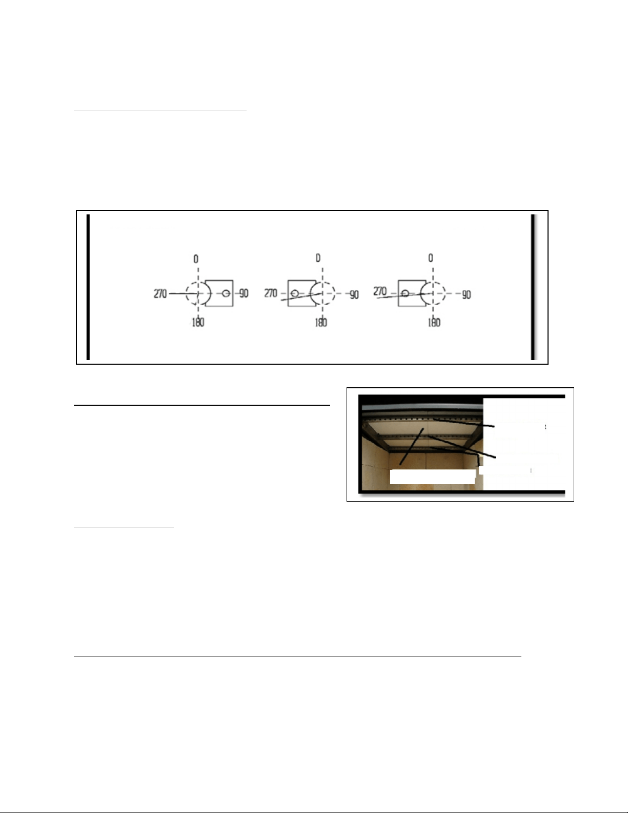
Page| 25
REMPLACEMENTDESCOMPOSANTS
Remplacement dutube debrûleur
Troistubesdifférentsdebrûleursetrouventdanslapartiesupérieuredupoêle.Pour
remplacer un tube, assurez‐vous de commander le tube qui correspond à celui que vous
devezremplacer.Retirezensuitelavissituéeducôté gauchedutubeàl’aided’unedouille
oud’une clé à fourches de
5/16po. Assurez‐vous de conserver la vis. Poussez le tubevers
ladroite, puis retirez‐le (en tirant le tube vers l’arrière et vers la gauche après avoir retiré
letubedececôtédel’orifice).Pourremplacerletube,inversezlaprocédureindiquée
ci‐dessus.Assurez‐vousd’installerlestubesdansl’ordreadéquat.(Del’avantàl’arrière)
Remplacementdu panneau enfibresdecéramique
Pourremplacerunpanneaufissuréoubrisé,
retirezd’abordletubedebrûleuravant.Retirez
ensuitelepanneauquevousdevezremplacer.
Installezlenouveaupanneau(les deuxpanneaux
doiventêtreplacésdirectement surlestubesde
bordàbord).Remplacezletuberetiré
précédemment.
Charnières deporte
Lescharnièresdecetappareilsontréglables.Lesplaquessontfixéesàl’aided’un
boulonetd’unécroude1/2po.Pourréglerlesplaquesdecharnièreversl’intérieurouvers
l’extérieur,retirezd’abordlaporte,puisdesserrezleboulonetl’écrouàl’aided’unedouillede
1/2poetd’unecléàfourchesde1/2po(unesurl’écrouetunesurlatêtedeboulon).Faites
coulisserlaplaqueversl’intérieurouversl’extérieur,puisserrezleboulonetl’écrouàl’aide
deladouilleetdelaclé.*Soyezvigilantlorsduréglagedescharnières.Sivousnelaissezpas
suffisammentd’espacepourledégagemententrelaporteetlecôtédel’appareil,lacharnière
risquedesebriser.*
Retraitdel’écranthermiqueetdupanneauarrière(pouraccéderauxautrescomposants)
Deuxvisde5/16posetrouventàl’arrièredel’écranthermique.Pourretirerl’écran
thermique,enlevezlesdeuxvisàl’aided’unedouilleoud’unecléàfourchesde 5/16po. Tirez
ensuitel’écranthermiqueverslehautetrepoussezversl’arrièrelepanneauarrière.Vousdevez
ensuiteretirertroisvisde5/16poquisetrouventàl’arrièredupanneau.Àl’aided’unedouille
oud’unecléàfourchesde5/16po,retirezlestroisvis.Ilpeutêtrenécessairedesouleverla
partiesupérieuredupanneauàl’aided’untournevisàlameplate(ausommetdupoêle).
Soulevezlepanneauetretirez‐ledupoêle.
PARTIEAVANTDUPOÊLE
PARTIEARRIÈREDUPOÊLE
270DEGRÉS 260DEGRÉS 265DEGRÉS
TUBEDEBRÛLEUR
CENTRAL
TUBEDEBR
Û
LEURARRI
È
RE
PANNEAUXENFIBRESDE
CÉRAMIQUE
TUBEDEBRÛLEUR
AVANT
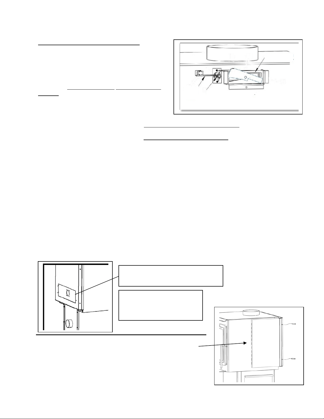
Page| 26
Remplacement desautres composants:
Àcepoint,vouspouvezaccéderàl’ensemblede
clapetd’évacuationd’airprimaire,àl’ensemble
d’actionneurthermostatiqueetaulevierde
déverrouillagederegistre.Vouspouvezfacilement
remplacercescompos ants.Toutefois,ilnedevrait
pasêtrenécessairedelesremplacer.Vo us pouvez
remplacerl’ensemble declapetd’évacua tion d’air
primaireenretirantlapetitepoi gnéeàressortdela
partieavantdel’appareil,puisenfaisant glisser
l’ensemblehor sdel’appareil.Replacezlecomposant
enfaisantglisserlenouvelensembledanslemême
trouetlatige danslapartieavantdupoêle.Replacezla
poignéeàressort.Vouspouvezremplacerl’ensemble d’actionneur thermostatiqueàl’ai ded’unedouille
de15/16poenretirantlesdeuxvisquiretiennentl’ensemble.Installezlenouvelensembleàl’aidedes
mêmesdeuxvis.Vouspouvezremplacerlelevier dedéverrouillage deregistreenretirantleboulonde
1/2po.Lorsdelaréinstallationduregistre, assurez‐vousqu’ilestinstallécommeilétaitlo rs deladépose.
ACCESSOIRESENOPTION
Ventilateur:Lepoêleàboisaaussiétéconçupouruneutilisationavecunventilateurdeconvection
pourassurerunecirculationdechaleursupplémentaire.Lepoêleestmunideprofilésdeconvectionqui
permettentauventilateurdepièced’extrairelachaleurdeszoneslespluschaudesdupoêleetde
la
transférerdanslamaison.Lesvisdemontageduventilateursontinstalléesdansleprofilédeconvection
arrièreàl’usine.Lemontageduventilateurn’exigequ’unedouilleouunecléàfourches de5/16popour
retirercesvisetinstallerleventilateur.Lorsdel’acheminementducordond’alimentation,
prenezsoin
delegarderàl’écartdeszoneschaudesdel’appareilet n’oubliezpasqueceventilateurnedoitêtre
utiliséqu’aveclepoêle.Consultezleschémaci‐dessouspourobtenirplusdeprécisionssurl’installation
duventilateurdepièce.CetappareilpeututiliserleventilateurAC‐16(offertde
sérieavecl’appareil)ou
lanouvelleversiondeventilateurAC‐30.Lesdeuxversionssontinstalléesàl’aidedesquatrevisde
5/16poposéesàl’usine.
Leventilateurdecirculationdechaleurenoptionsurcepoêlenécessiteungraissagepériodiqueeffectuéaumoins
touslestroismoisenutilisationnormale.Pourgraisserdefaçonappropriéeleventilateur,utilisezuncompte ‐
gouttesoculaireouundispositifsimilairepourappliquerde5à7 gouttelettesd’huileSAE20
dansl’orificed’huile
ducôtédumoteurduventilateur.
Écranthermiquelatéral(pièceAC‐W01SHS):
Installezl’écranthermiquederrièrelerebordlatéraldupanneau
arrière.Alignezlesdeuxtrousdemontage,puisfixez‐leàl’aide
desdeuxvisfournies.
Avertissement:Coupez
l’alimentationélectriquedu
ventilateuravantl’installation.
(4)visautotaraudeuses,têtede5/16po
(préinstalléesdansl’appareil).
Levierde
déver‐
rouillage
deregistre
Ensembled’actionneurthermostatique
Ensembledeclapet
d’évacuationd’air
primaire

Page| 27
DÉPANNAGE
Problème Cause Solutions
Lepoêleémetdelafumée 1.Tiragefaible 1.1Assurez‐vousquelalongueurdelacheminée
danslapièce. estsuffisantepourrespecterlarègle10‐3‐2.
1.2Augmentezlahauteurdelacheminée.
2.Pressionnégative
danslelogement
2.1Ajoutezunraccordementd’aircomburant
extérieurà
l’appareil.
Lefeuestdifficileàdémarrer. 3.Tiragefaible 3.1Assurez‐vousquelalongueurdelacheminée
estsuffisantepourrespecterlarègle10‐3‐2.
3.2Augmentezlahauteurdusystèmede
cheminée.
4.Cheminéefroide 4.1Chauffezlabuseenpremierenbrûlantdu
papierjournal
chiffonnédanslepoêle.
4.2Installezunechasseisoléeautourdes
cheminéesextérieures.
5.Contre‐tirage
danslacheminée
5.1Assurez‐vousquelalongueurdela
cheminéeestsuffisantepourrespecterla
règle10‐3‐2.
5.2Essayezdechaufferlabuseavecun
séchoiràcheveuxpourcorriger
letirage.
Lavitreestsale. 6.Boishumideouvert 6.1Brûlezseulementduboisquiaséchéaumoins
unanetquiestsec,exemptdeglaceetdeneige.
7.Utilisationdupoêle
àuntauxde
combustionbas
8.Leboischargéest
tropprès
delavitre.
Accumulationdebraisesdans 9.Utilisationdupoêle
lachambredecombustion. àuntauxdecombustion
élevé
7.1Faitesfonctionnerlepoêleàuntauxde
combustionplusélevéafindepermettreau
systèmeautonettoyantdeconserverlavitre
propre.
8.1Nechargezjamaislebois
desortequ’il
toucheàlafenêtreenverrevitrocéramique.
9.1Réduisezl’admissiond’aircomburantet
permettezauxbraisesdebrûleravantde
rajouterdubois.
Lefeuesthorscontrôle. 10.Tirageexcessif 10.1Réduisezlahauteurdelacheminée.
11.Fuited’air 11.1Inspectezlesjointsd’étanchéitéde
la
fenêtreetdelaporteetremplacez‐lesaubesoin.
12.Boisdechauffage
tropsec
Lacheminéedégageune 13.Utilisationdupoêle
fuméeexcessive. àuntauxdecombustion
bas
14.Boishumideouvert
15.Nouvellechargede
boisquines’enflamme
pas
12.1
Brûlezseulementduboisenstérésec.Ne
faitespasbrûlerduboisséchéauséchoiroudu
boisàpalettes.
13.1Faitesfonctionnerlepoêleàuntauxde
combustionplusélevépouractiverlacombustion
secondaire.
14.1 Brûlezseulement du bois qui a séché au
moinsunanetqui
estsec,exemptdeglaceet
deneige.
15.1Faitescarboniserlanouvellechargedebois
jusqu’àcequ’elles’enflammecomplètementet
quelacombustionsecondaireactiveseproduise
danslachambredecombustion.

Page| 28
LISTE DES PIÈCES DE RECHANGE
N°surle
schéma
Description
N°depièce
Par
unité
7 Écranthermiquearrière(BOULONNÉ) AC‐W01HS 1
6 Panneauarrière(BOULONNÉ) AC‐W01RP 1
1
Ensembledeclapetd’évacuation
d’airprimaire
AC‐W01PDA 1
Nonillustré Levierdedéverrouillagederegistre AC‐W01DRL 1
Nonillustré Ensembled’actionneurthermostatique AC‐W01TAA 1
9 Tourmalin AC‐ADW01 1
10 Porte CA‐W01 1
14 Charnièresdeporte AC‐DHW01 2
Nonillustré Écransthermiqueslatéraux AC‐W01SHS
2
Nonillustré Grandventilateurnouvelleversion
(enoption)
AC‐30 1
Nonillustré Petitventilateurdesérie AC‐16 1
12 Troussedejointd’étanchéitédevitre
platde19,05mm
AC‐GGK 1
16 Troussedejo intd’étanchéitédeporte
hautedensitéde19,05mm
AC‐DGKHD 1
3 Tubedebrûleuravant AC‐W01FBT 1
17 Tubedebrûleurcentral AC‐W01MBT 1
4 Tubedebrûleurarrière AC‐W01RBT 1
13 Dimensionsdelavitrede AC‐G50 1
2 Panneauenfibresdecéramique AC‐W01CFB 2
Nonillustré Petitepoignéeàressort(nickeletlaiton) AC‐SH4N/AC‐SH4 1
Nonillustré Grossepoignéeàressort(nickeletlaiton) AC‐SHN/AC‐SH 1
8 Couverclearrièreduventilateur AC‐BBC30 1
15 Languettesdevitre AC‐W01GT 4
11 Axesdecharnière AC‐HP 2
Nonillustré Ensemblederaccordal’airexterieur
(enoption)
AC‐OAK3 1
*POUR LA DISPOSITION DES BRIQUES ET LES
NUMÉROS DE PIÈCE, CONSULTEZ LA PAGE30.*
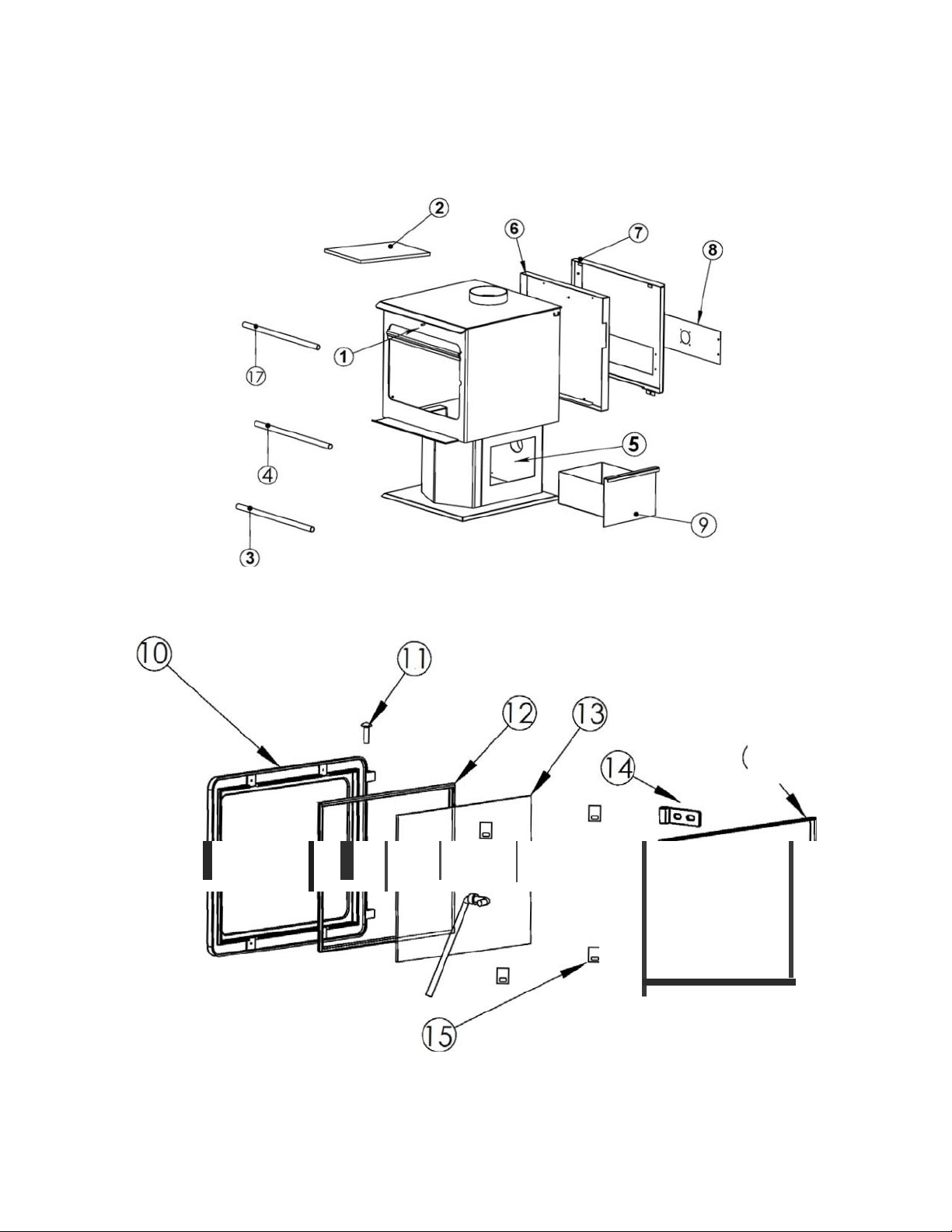
Page29
SCHÉMA DES PIÈCES
16
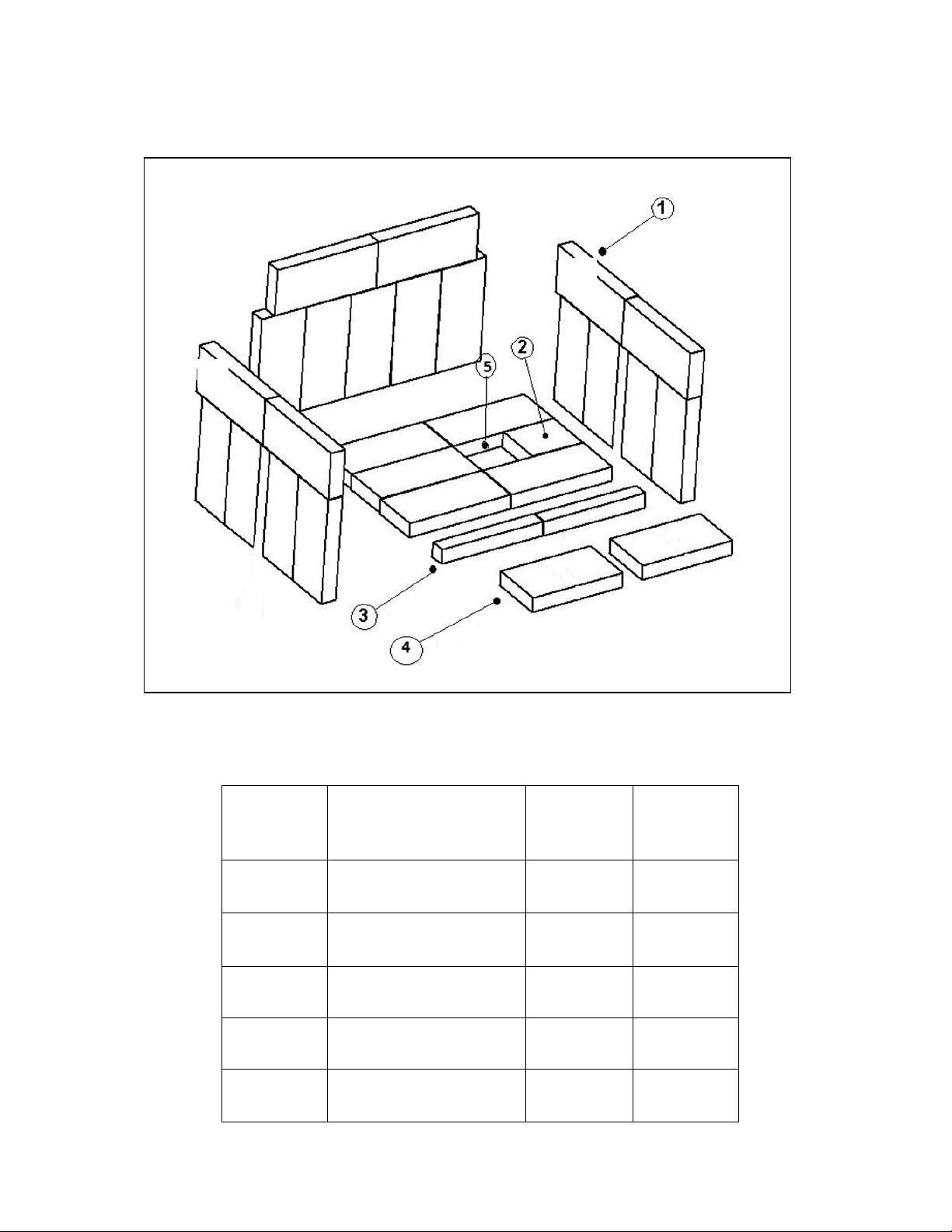
Page|30
DISPOSITION ET REMPLACEMENT DES BRIQUES
REMARQUE:Lesbriquessurlescôtésetàl'arrièredoiventêtreinstallésaprèsl'accouchement
*Topbriquesarrièredechaquecôtépeuventounonêtreentaillés.Sientaillé,commanderlenuméro
depièceAC‐SBN1X3.
NUMÉRO
DESCHÉMA
DIMENSIONSDES
BRIQUES
NUMÉRO
DEPIÈCE
QUANTITÉ
PARPOÊLE
1 22,86cmx10,16cmx
3,18cm
AC‐SB 24
2 11,43cmx10,16cmx
3,18cm
AC‐SB4.5 1
3 19,69cmx5,72cmx
3,18cm
AC‐SB7.75X2.25
2
4 19,69cmx10,16cmx
3,18cm
AC‐SB7.75 2
5 Trappeacendres CA‐30ADP 1
*
*

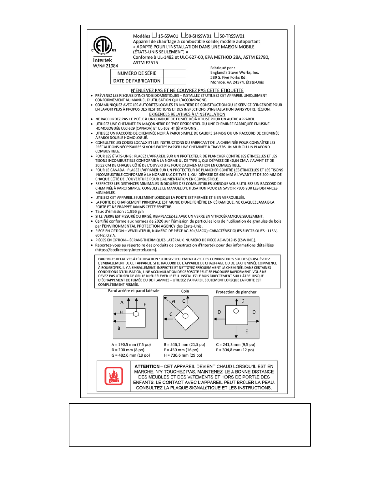
Page|31
Vous pouvez inscrire la date de fabrication et le numéro de série de votre appareil
dans les espaces prévus à cet effet sur cette étiquette, pour référence ultérieure. Cette
étiquette comprend également des renseignements de sécurité, comme la norme
d’essai UL (ULC au Canada), à l’intention de vos représentants locaux ou de toute
autre personne qui peut en avoir besoin.

Page| 3
2
Cette garantie est non transférable.
GARANTIE LIMITÉEDE CINQ (5) ANS
Àpartirdeladated’achatparlepropriétaired’origine
Lagarantielimitéedufabricantcouvrelesélémentsci‐dessous:
Cinq ans:
1. Lesjointsd’acieraucarboneetlesjointssoudésdufoyersontgarantis
pendantcinq(5)anscontrelafissuration.
2. Laporteetlescharnièresenfontesontgarantiespendant
cinq(5)anscontrelefendillement.
Un an:
1. Lescomposantsélectriques,lesaccessoires,leverreetlasurfacepeinte
dupoêlesontgarantispendantun(1)anàpartirdeladated’achat.
Conditions et exclusions
1. Lesdommagescausésparunemballementannulentvotregarantie.
2. Cettegarantienes’appliquepassilesdommagessontcausésparun
accident,unemanipulationinappropriée,uneinstallationinadéquate,une
utilisationincorrecte,unusageabusif,uneréparationnonautoriséeou
unetentativederéparationnonautorisée.
3. Lefabricantn’estpasresponsabledesdommagesindirects,
accessoiresouconsécutifsdécoulantduproduit,ycomprislescoûtsou
dépenses,lafournituredematérielderechangeoularéparationpendant
lespériodesdemauvaisfonctionnementoudenon‐utilisationduproduit.*
4. Lefabricantdéclineratouteresponsabilitépourlesdommages
consécutifsencas
deviolationdetoutegarantieécriteouimplicite.
5. Cettegarantienecouvrepasl’usuredespiècesinternesdusystème
decombustion,ycomprislerevêtementenvermiculitedelachambreà
combustionetlesjointsd’étanchéité.
**CertainsÉtatsoucertainesprovincesnepermettentpasl’exclusionoulalimitationdesdommagesaccessoiresouconsécutifs,de
sortequelesexclusionsmentionnéesci‐dessuspeuventnepass’appliqueràvous.**
Procédure
L’acheteurdoitsoumettreuneréclamationpourdéfautpendantlapériodede
garantieetpayerletransportverslecentredeserviceetàpartirducentrede
servicedésignéparlefabricant.Lerevendeurquiavendul’appareiloule
fabricant,ànotregré,effectueralaréparationsousgarantie.
Autres droits
Cettegarantievousconfèredesdroitsprécis.Ilestpossiblequevousdisposiez
égalementd’autresdroits,quivarientd’unÉtatoud’uneprovinceàl’autre.
Veuillez noter: Cette garantie est nulle et non avenue si l’acheteur n’envoie pas la
carte d’enregistrement de la garantie ci-jointe ET une copie du reçu de vente dans
les trente(30)jours, à compter de la date d’achat.

Page| 33
Avis important
Pour que la présente garantie soit valide, nous DEVONS recevoir et conserver dans
nos dossiers cette information relative à l’enregistrement. Veuillez nous envoyer
cette information dans les trente(30)jours suivant la date d’achat originale.
Il y a troismoyens faciles de nous faire parvenir cette information.
Adresse postale
England’s Stove Works, Inc.
Technical Support Department
P.O. Box206
Monroe, Virginia24574,
États-Unis
Télécopieur
1434929-4810–24heures par jour.
Enregistrement en ligne
Consultez notre page d’enregistrement de
la garantie sur notre site Web à:
http://www.heatredefined.com
(LA CARTE DE GARANTIE SE TROUVE À LA PAGE
SUIVANTE.)

Page| 3
4
ENREGISTREMENT DE LA GARANTIE sur les produits
England’s Stove Works®
Renseignements sur l’acheteur
I.Nom de l’acheteur
II. Adresse
III. Ville État ou province Code postal
IV. Numéro de téléphone
V.Courriel
Renseignements sur le détaillant
VI. Nom du détaillant
VII. Adresse
VIII. Ville État ou province Code postal
Renseignements sur l’appareil
*Veuillez consulter l’étiquette à l’arrière du guide ou de la boîte pour remplir
cette section. IX. Numéro de modèle Date d’achat
X.Prix d’achat
XI. Numéro de série Date de fabrication
Questions relatives à l’achat
Comment avez-vous entendu parler de notre produit? (Veuillez cocher l’une des
réponses suivantes.)
De bouche à oreille
Démonstration
Sur Internet
Autre:
À quel endroit vous a-t-on donné des renseignements sur notre produit?
Au téléphone Chez un détaillant
(nom du détaillant)
Sur
Internet
Autre:

RENSEIGNEMENTSSURL’EPA
Lesajoutssuivantsàvotreguided’utilisationvouspermettrontderéduireau
minimumlesémissionsproduitesparvotrepoêleàbois.Desconseilsdesécurité
importantsvoussontégalementprésentés.
‐ Installationadéquate–Veuillezconsulterlasectionsurl’installationdevotreguide
d’utilisationetsuivrelesdirectivesénoncéesafind’assurerlasécuritéetderéduireau
minimumlesémissions.
Renseignementssupplémentaires:
Généralitéssurlaventilation:
Tirage:Letiragedésignelaforcequidéplacel’airdel’appareiljusquedanslacheminée.La
puissance du tirage dans votre cheminée dépend de la longueur de la cheminée, de la
géographie locale, des obstructions à proximité et d’autres facteurs. Un tirage trop élevé
peutentraînerdestempératurestropélevéesdansl’appareiletendommagerlachambrede
combustioncatalytique.Untirageinadéquatpeutentraînerunrefoulementdefuméedans
lapièceetobstruerlacheminéeoulecatalyseur.
Untirageinadéquatentraîneradesfuitesdefuméedanslapièceparlesjointsderaccordde
l’appareiletdelacheminée.
Un taux de combustion incontrôlable ou une température trop élevée indique un tirage
excessif.
Soyezconscientdel’emplacementdel’installation:unrefoulementetd’autresproblèmes
dequalitédel’airpeuventsurvenirdanslesvalléesousil’appareilestinstalléàproximité
d’habitationsvoisines.
Cepoêleàboisutiliseunsystèmedetiragenatureldanslequellesystèmedecheminée
tirel’airdanslepoêle.Cetappareildoitêtreinstalléconformémentauxtechniquesdeventilation
décritesendétailci‐après.Lenon‐respectdesdétailsmentionnéspourraitréduireson
rendementetcauserdesdommagesmatériels,desblessuresoulamort.Évitezd’avoirrecoursà
desexpédientslorsdel’installationdusystèmedeventilation.England’sStoveWorksn’estpas
responsabledesdommagescausésparuneinstallationincorrecteounonsécuritaire.
Assurez‐vousdebiensuivretouteslesinstructionsdufabricantrelativesausystèmede
ventilation,surtoutparrapportauxdistancesminimalesnécessairesaveclesmatières
combustibles.Assurez‐vouségalementd’utiliserunécranantirayonnementdegrenierafin
d’éviterquel’isolantentreencontactavecunecheminéequitraverseungrenier.
Lesystèmedecheminéeestle«moteur»dupoêleàbois.Ilestdoncessentielquele
systèmedeventilationsoitinstalléexactementselonladescriptionindiquéedanslasection
suivanteafind’assurerunfonctionnementadéquatdel’appareil.
Pourtoutequestionrelativeàl’installationsécuritairedupoêle,appeleznotreservice
desoutientechniqueau1800245‐6489.Communiquezavecunagentresponsablelocalafinde
vousassurerquel’installationestconformeauxexigencesmunicipalesetnationalesenmatière
depréventiondesincendies.Sivousn’êtespascertaindepouvoirinstallerlepoêlede
Certifiéconformeauxnormesde2020surl’émissiondeparticuleslorsdel’utilisation
degranulesdeboisparl’ENVIRONMENTALPROTECTIONAGENCYdesÉtats‐Unis.

Page| 3
4
sécuritaire,nousvoussuggéronsfortementdefaireappelàuninstallateurlocalcertifiéparleNFI
(NationalFireplaceInstitutedesÉtats‐Unis).
Consignespourlaventilation:
• InstallezTOUJOURSletuyaudeventilationenrespectantrigoureusementlesinstructions
etlesindicationssurlesdégagementsquiaccompagnentlesystèmedeventilation.
• NeraccordezPASlepoêleàboisàunconduitdefuméedéjàutilisépourunautreappareil.
• N’INSTALLEZPASunrégulateurdetirage
niaucunautred is p os it ifderéglagedanslesystèmed’évacuationparventilationdecetappareil.
• UTILISEZunmanchond’emboîtementmuralhomologuépourtraverserunmuretunsupport
deplafondouuncoupe‐feupourtraverserunplafond.
• INSTALLEZtroisvisàtôlesurchaquejointderaccorddecheminée.
• ÉVITEZ de trop nombreux coudes et parcours horizontaux, car ils réduiront le tirage du
systèmedeventilation,cequinuiraaurendementdupoêle.
• INSPECTEZsouventlesystèmedeventilationafindevousassurerqu’ilnecontientpasde
créosote,decendresvolantesoud’autresobstructions.
• NETTOYEZlesystèmedeventilationcommeilestdécritdanslasectionsurl’entretiendu
présentguide.
• RESPECTEZlarègle10‐3‐2concernantlesraccordementsdelacheminée.
• INSTALLEZleraccorddecheminéeàparoisimpleavecl’extrémitémâleverslebaspour
éviterlesfuitesdecréosote.Suivezlesinstructionsdufabricantderaccordsdecheminéeà
paroidoubleconcernantl’installationadéquatedestuyaux.
AVERTISSEMENT:LessurfacesdusystèmedeventilationdeviennentCHAUDESetpeuventcauser
desbrûluressivouslestouchez.Ilpeutêtrenécessaired’utiliserunrevêtementoudesgrillesde
protectionincombustibles.
Règle10‐3‐2:Lesystèmedecheminéedoitseterminerà0,91m(3pi)au‐dessusdupointoùson
axecentraltraverseletoitETlacheminéedoitseterminerà0,61m(2pi)au‐dessusdetoute
partiedulogementdansunrayonde3,05m(10pi)delacheminée.
‐ Fonctionnementetentretien–Consultezlessectionssurlefonctionnement(mode
d’emploi)etl’entretien(ycomprisleretraitetl’éliminationdescendres)devotreguide
d’utilisationetsuivezlesdirectivesénoncéespourassurerlasécuritéetréduireau
minimumlesémissions.
Renseignementssupplémentaires:
Respectezlesinstructionsdevotreguided’utilisationconcernantl’allumaged’unfeuafinde
produireunfeuappropriéetderéduirelesémissionsvisibles.
Plus:
‐ Alimentationencombustibleetréalimentation:Conseilspratiquespourfaireunfeu–
Consultezvotreguided’utilisationpourobtenirdesrenseignementssurl’alimentation
encombustible(etlaréalimentation)ainsiquesurlesprocéduresd’allumagedefeu
(c.‐à‐d.,faireunfeu).
‐ Allumageduhautverslebas:L’EPAreconnaîtl’efficacitédelaméthoded’allumagedu
hautverslebas.Voustrouverezunbontutorielsurcetteméthodeau
http://woodheat.org/top‐down‐steps.html.Pourallumerunfeuduhautverslebas,
assurez‐vousdesuivrelesinstructionsdevotreguided’utilisationetcommuniquezavecle
servicedesoutientechniquesivousavezdesquestions.

‐ Sélectionducombustible:Lorsquevotreappareildechauffageauboisestcorrectement
installé,vousdevrezutiliserunbonboisdechauffagepourallumerunfeuefficace(lebon
boisenquantitésuffisante)ainsiqueconnaîtredebonnesméthodesd’allumagedefeu.
Lesétapespratiquessuivantesvousaiderontàtirerlemeilleurrendementdevotrepoêle
àboisoufoyer.
Laissezvotreboissécheràl’extérieurtoutl’étépendantaumoinssixmoisavantdele
brûler.Unboiscorrectementséchéestplusfoncé,présentedesfissuressurlefil
d’extrémitéetsonnecreuxlorsquevouslecognezcontreunautremorceaudebois.
Conservezvotreboisàl’extérieur,bienempilésurlesolavecuneprotectionau‐dessus.
Nebrûlezqueduboisbiensecquiaétécorrectementfendu.
Pourallumerunfeu,utilisezuniquementdupapierjournaletduboisd’allumage,comme
ilestmentionnéprécédemmentdansleguide.
Faitesdesfeuxchauds.
Pourmainteniruneventilationadéquate,retirezrégulièrementlescendresdevotre
appareildechauffageauboisdansunrécipientenmétaldotéd’uncouverclequevous
conserverezàl’extérieur.
Renseignementssurl’humidimètre
Leboisdechauffagepeutêtrebrûlélorsqu’ilauneteneurenhumiditéde10à25%.
Lesbûchesfraîchementcoupéespeuventavoiruneteneurenhumiditéde80%ouplus,
selonl’essencedubois.Puisqueleboisrétrécit,etpeutégalementsefendre,setordreou
autrementchangerdeformeenséchant,laplupartdesboisdoiventêtreséchés avant
d’êtreutilisés.Leséchageàl’airestla méthodelaplusfréquemmentutiliséepourlebois
enstéré.DanslaplupartdesrégionsdesÉtats‐Unis,lateneurenhumiditéminimalequ’ilest
possibled’obtenirparunséchageàl’airestd’environ12à15%.Laplupartdesmatériaux
séchésàl’airontuneteneurenhumiditéavoisinant20%lorsqu’ilssontutilisés.
Pourvérifierlateneurenhumiditédevotreboisdechauffage,enfoncezsimplement
lestigesdansleboisetattendezlalecturedel’humidimètre.Souvenez‐vousdene
pasenfoncerlestigesdel’humidimètreuniquementdanslesextrémitésduboisde
chauffage.Pourobtenirunelectureprécise,fendezlabûcheetfaitesletestaucentre.Le
centredelabûchecontiendralaplusforteteneurenhumidité.
Àquelledistancedois‐jeenfoncerlestigesnonisoléesdanslebois?
Jusqu’àuneprofondeurmaximale,sic’estpossible.Toutefois,àdestauxd’humidité
inférieursà10%,ilestgénéralementsuffisantdecréeruncontactfrancaveclebois.Àdes
tauxd’humiditésupérieurs,etparticulièrementsil’inclinaisonestgrande,unepénétration
complèteestessentielle.

Page| 3
4
‐ COMBUSTIBLESÀÉVITER:
MISEENGARDE
N’UTILISEZJAMAISD’ESSENCE,DECOMBUSTIBLEPOURLAMPEAPPARENTÉÀL’ESSENCE,DE
KÉROSÈNE,DELIQUIDED’ALLUMAGEPOURCHARBON,NIAUCUNLIQUIDESIMILAIREPOUR
ALLUMEROURAVIVERUNFEUDANSCETAPPAREILDECHAUFFAGE.CONSERVEZDETELS
LIQUIDESÉLOIGNÉSDEL’APPAREILDECHAUFFAGELORSQUECELUI‐CIFONCTIONNE.DEPLUS,
NEDISPOSEZJAMAISD’ALLUME‐FEUXSURUNESURFACECHAUDENISURDESTISONSDANSLE
POÊLE.N’UTILISEZPASDEPRODUITSCHIMIQUESNIDEFLUIDES
POURALLUMERLEFEU.
NEFAITESPASBRÛLERDELIQUIDESINFLAMMABLESCOMMEDEL’ESSENCE,DUNAPHTA
OUDEL’HUILEPOURMOTEUR.
NEFAITESPASBRÛLERDESDÉCHETS,DUGAZONCOUPÉOUDESRÉSIDUSDEJARDINAGE,DES
MATÉRIAUXCONTENANTDUCAOUTCHOUC,YCOMPRISDESPNEUS,DESMATÉRIAUX
CONTENANTDUPLASTIQUE,DESDÉCHETSDEPRODUITSPÉTROLIERS,DELAPEINTUREOUDU
DILUANTÀPEINTURE,DESPRODUITSBITUMINEUX,DESMATÉRIAUXCONTENANTDE
L’AMIANTE,DESDÉBLAISOU DESDÉBRISDECONSTRUCTION,DESTRAVERSESDECHEMINDE
FEROUDUBOISTRAITÉSOUSPRESSION,DUFUMIEROUDESRESTESD’ANIMAUX,DUBOISDE
GRÈVEIMPRÉGNÉD’EAUSALÉEOUDESMATÉRIAUXPRÉALABLEMENTSATURÉSENEAUSALÉE,
DESPRODUITSDEPAPIER,DUCARTON,DUCONTREPLAQUÉOUDESPANNEAUXDEPARTICULES.
L’INTERDICTIONDEBRÛLERCESMATÉRIAUXNEVOUSEMPÊCHEPASD’UTILISERDESALLUME‐
FEUÀBASEDEPAPIER,DECARTON,DESCIURE,DECIREOUD’AUTRESSUBSTANCES
SEMBLABLESPOURALLUMERUNFEUDANSLEPOÊLEÀBOIS.LACOMBUSTIONDECES
MATÉRIAUXPEUTCOMPROMETTREL’EFFICACITÉDUPOÊLEETPRODUIREDELAFUMÉEETDES
VAPEURSTOXIQUES.
‐ Pratiquesdechauffageauboissécuritaires
Unefoisquevotreappareildechauffageauboisestcorrectementinstallé,suivezcesdirectivespour
assurerunfonctionnementsécuritaire:
Conserveztouslesarticlesdemaisoninflammables(draps,meubles,journauxetlivres)loinde
l’appareil.
Pourallumerunfeu,utilisezuniquementdupapierjournal,duboisd’allumageetunallume‐feu
entièrementnatureloubiologique.N’utilisezjamaisd’essence,dekérosèneoud’allumoirà
charbonpourallumerunfeu.
Nebrûlezpasdebûcheshumidesouvertes(nonséchées).
N’utilisezpasdebûchesfaitesdecireoudesciuredeboisdansvotrepoêleàbois,carellesso nt
conçuespourdesfoyersouverts.Sivousutilisezdesbûchesfabriquées,prenezcellesquisont
faitesdesciuredeboiscompresséeà100%.
Faitesdesfeuxchauds.Pourla plupartdesappareilsdechauffageaubois,unfeuquicouven’estni
sécuritaireniefficace.
Gardezferméeslesportesdevotreappareildechauffageauboissaufpourajouterdesbûchesou
alimenterlefeu.Desproduitschimiquesnocifs,commelemonoxydedecarbone,peuventêtre
libérésdansvotredomicile.
Retirezrégulièrementlescendresdevotreappareildechauffageauboisdansunrécipienten
métaldotéd’uncouvercle.Rangezlerécipientcontenantlescendresàl’extérieur,surunedallede
cimentoudebrique(etnonpassuruneterrasseenboisniàproximitédebois).Consultezles
instructionssurleretraitdescendresdansleguided’utilisation.
Gardezunextincteurd’incendieàportéedelamain.
N’oubliezpasdeconsulterlesprévisionslocalessurlaq ualitédel’airavantd’utiliservotrepoêleàbois.

‐ Commanded’air:CONSULTEZVOTREGUIDED’UTILISATIONpourobtenirplusde
renseignementssurl’utilisationappropriéedelacommanded’air(danslasection
Fonctionnement).
‐ RETRAITDESCENDRES–Suivezlesinstructionsduguided’utilisationconcernantleretrait
etl’éliminationdescendres.
‐ REMPLACEMENTdespiècesessentiellesàuntauxd’émissionfaible–Suivezles
instructionsduguided’utilisationconcernantleremplacementdesjointsetdesautres
piècesessentiellesàuntauxd’émissionfaible.
Rappel:«Afind’assurerlebonfonctionnementdupoêleàbois,vousdevezl’inspecteretle
réparerpériodiquement.Envertudesrèglementsfédéraux,ilestinterditd’utilisercepoêleàbois
d’unemanièrenonconformeaumoded’emploiindiquédansleprésentguide.»
Plus:Tubesdebrûleur–Pourremplaceruntube,assurez‐vousdecommanderletubequi
correspondàceluiquevousdevezremplacer.Retirezensuitelavissituéeducôtégauchedutube
àl’aided’unedouilleoud’unecléàfourchesde5/16po.Assurez‐vousdeconserverlavis.
Poussezletubeversladroite,puisretirez‐le(enramenantletubeverslagaucheaprèsavoir
retirécecôtédel’orifice).Pourremplacerletube,inversezlaprocédureindiquéeci‐dessus.
Assurez‐vousd’installerlestubesdansl’ordreadéquat.(Avantversl’arrière)
‐ Détecteursdefumée
England’sStoveWorks,Inc.recommandefortementl’utilisationdedétecteursdefuméedans
chaquepiècedelamaison.Cependant,lefaitdeposerundétecteurdefuméedirectement
au‐dessusdel’appareilpourraitcauserdesalarmesintempestives.
MISEENGARDE
Cetappareilestconçupourfonctionneruniquementlorsquelaporteestfermée.L’utilisation
dupoêleaveclaporteouverteprovoqueraitunrefoulementdefuméeetunecombustionlente
etinefficace.
Deplus,l’utilisationdecombustiblesinterditspeutêtredangereuseetproduireunexcèsde
monoxydedecarbone.Lemonoxydedecarboneestungazmortelquiestinodoreetincolore.
Ilestfortementrecommandéd’utiliserundétecteurdemonoxydedecarbone.
Conformité : « Certifiéconformeauxnormes de2020surl’émissiondeparticuleslorsde
l’utilisationdegranulesdeboisparl’ENVIRONMENTALPROTECTIONAGENCYdesÉtats‐Unis.
»
‐ Avertissementrelatifauxmodifications:«Cepoêleàboisestdotéd’untaux de
combustionbasminimumrégléenusinequinedoitpasêtremodifié.Envertudes
règlementsfédéraux,ilestinterditdemodifierceréglageetd’utilisercepoêleàbois
d’unemanièrenonconformeaumoded’emploiindiquédansleprésentguide.»
‐ Garantie:Consultezvotreguided’utilisationpourobtenirleformulaired’enregistrement
delagarantieetconnaîtrelesinstructionsrelativesauxprocéduresdelagarantie.Dansle
casdespièces,lesprocéduresderemplacementautitredelagarantiesetrouventsurle
sitedenotremagasindepièces:www.heatredefined.com