Loading ...
Loading ...
Loading ...
Installation
Installation
18
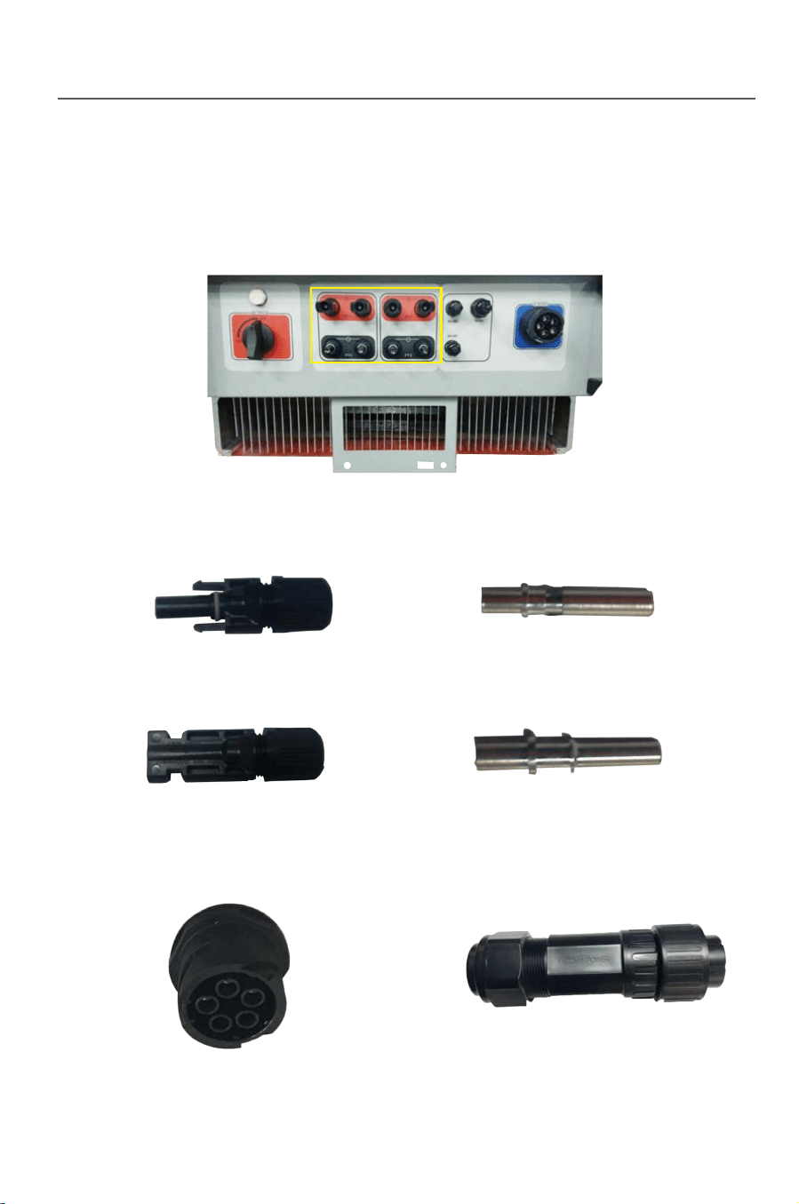
3.6.3 Wiring terminals and cable specification
1) DC wiring terminals
Fig.3-15 Fig.3-16
Fig.3-17 Fig.3-18
19
3) Communication terminals
2) AC terminals
Fig.3-14
Fig.3-19 Fig.3-20
Fig.3-21
The DC side of inverter has 4 pairs of terminals in total.See the figure below:
4) Cables of the following specification will be equipped by the user.
Tab.3-5: Recommended cable specification
DC cable
AC cable
cable (RS485)
Name
Model Recommended cable type
Recommended wire
diameter mm
All of the above cables are copper wire
TP10KTL-TP20KTL
TP10KTL-TP20KTL
TP10KTL-TP12KTL
TP15KTL-TP20KTL
4 core outdoor cable
Photovoltaic cable
2 core outdoor twisted-pair
shielded wire
4mm
3*4mm +1*2.5mm
3*6mm +1*4mm
2*1mm
2
2
2
2
2
2
2
Danger
Danger
3.6.4 Steps for electrical connection
If the inverter has been electrified and tested before
connection, wiring can not be performed unless the AC and
DC power supplies are cut off for 10min and a multimeter
shows that the DC side is tatally discharged.
Please cover the PV array by lightproof material or switch
off the DC circuit breaker before electrical connection. A
dangerous voltage will be generated by the PV array
exposed in the shine.
Loading ...
Loading ...
Loading ...