Loading ...
Loading ...
Loading ...
®
SPECIFICATION SUBMITTAL Page
Job Name:
Job Number:
Model Numbers:
CasétaR Wireless Load Controls
369987a 17 09.09.16
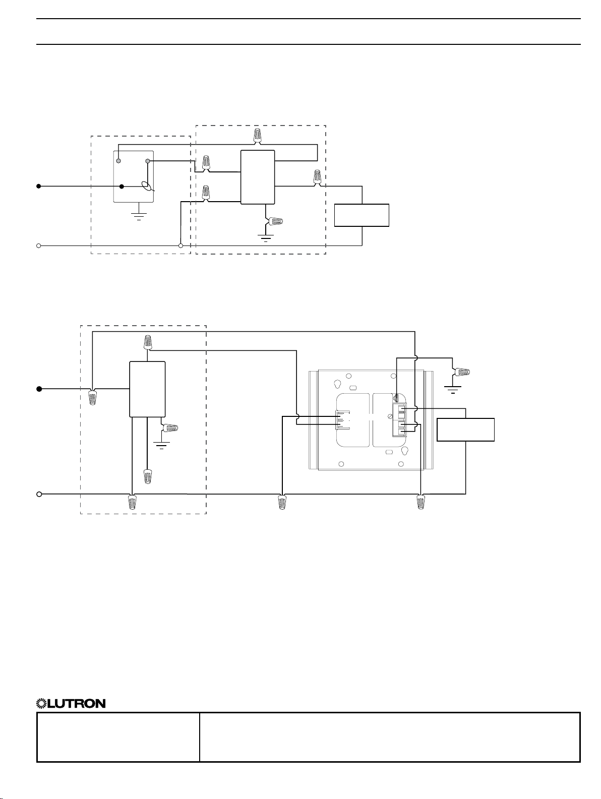
Wiring Diagrams - Dimmers (cont.)
3-Way Installation
With mechanical switch
In-Wall
Dimmer
2
Mechanical
Switch
2
Brass
Brass
Load
Line/Hot
Neutral
Green
Ground
Ground
Black
Red
Blue
120 V~
50/60 Hz
Black
Jumper wire
(included)
White
3
PD-10NXD
1
When using controls without mechanical 3-way switch, cap the blue terminal. Do not connect the blue wire to any other wiring or to ground.
2
Location of In-Wall Dimmer and mechanical switch may be reversed.
3
Neutral connection optional except for MLV loads, LED drivers, and power modules (PHPM-PA, PHPM-3F, and GRX-TVI).
4
See LutronR P/Ns 369356 and 369355 for additional wiring diagrams.
5
Blue wire is only present on the PD-10NXD model.
Installation with PHPM - Neutral required
4
L/H
N
DH
In-Wall
Dimmer
Neutral
Line/Hot
120 V~
60 Hz
Black
Ground
Ground
White
Green
Blue
1, 5
Red
PHPM
Load
Control Neutral
Zone In
PD-10NXD and PD-5NE
Location 1
Location 2
Location 1
17
Loading ...
Loading ...