Loading ...
Loading ...
Loading ...
®
SPECIFICATION SUBMITTAL Page
Job Name:
Job Number:
Model Numbers:
CasétaR Wireless Load Controls
369987a 13 09.09.16
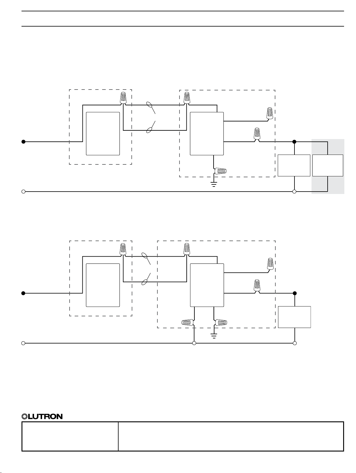
Wiring Diagrams - Switches (cont.)
1
When using controls without mechanical 3-way switch, cap the blue terminal. Do not connect the blue wire to any other wiring or to ground.
2
A LUT-MLC ensures proper function when LED, fluorescent, or ELV loads are used. Install the LUT-MLC inside a load fixture or in a separate junction box
within the circuit.
3
The mechanical switch will need to be removed so the PicoR Remote Control can be installed.
4
The red wire must be connected to the load and the black wire must be connected to Line/Hot. The switch will not work if the wires are reversed.
3-Way Installation (with PicoR remote controls)
Option 2: PJ2-2B-xx and wallbox mounting adapters (PICO-WBX-ADAPT)
(continued on next page…)
Black
Black
Black
Black
PD-5WS-DV
PD-6ANS
Pico
®
Remote
Control and
Wallbox
Mounting
Adapter
3
Pico®
Remote
Control and
Wallbox
Mounting
Adapter
3
LUT-MLC
2
Load
Load
Line/Hot
Line/Hot
Neutral
Neutral
Green
GreenWhite
Ground
Ground
Black
Red
4
Blue
1
Blue
1
120 / 277 V~ 50/60 Hz
120 V~ 50/60 Hz
Travelers
Travelers
PD-5WS-DV
PD-6ANS
Location 1
Location 1 Location 2
Location 2
13
Loading ...
Loading ...
Loading ...