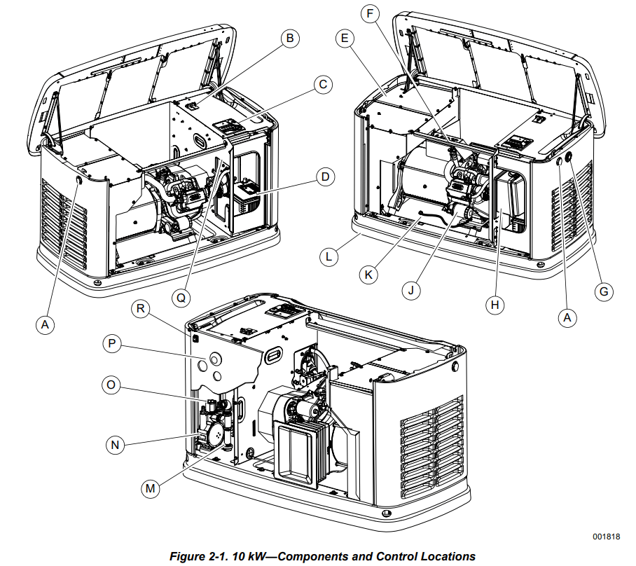
B Main line circuit breaker (generator disconnect)
G Status LED indicators
L Composite base
P Wi-Fi module
C Control panel
H Airbox with air cleaner
M Sediment trap
Q Data decal location
D Battery compartment (battery not supplied)
J Oil filter
N Fuel regulator
R Auxiliary shutdown switch
E Exhaust enclosure
A Lock with cover
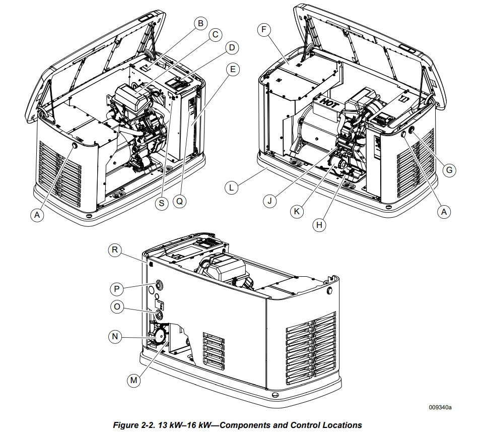
F Exhaust enclosure
L Composite base
Q Wi-Fi module
B Main line circuit breaker (generator disconnect)
G Status LED indicators
M Oil dipstick
R Data decal location
C Airbox with air cleaner
H Oil drain hose
N Sediment trap
S Auxiliary shutdown switch
D Control panel
J Oil fill cap
O Fuel regulator
T Auxiliary shutdown switch
E Battery compartment (battery not supplied)
K Oil filter
P Fuel inlet
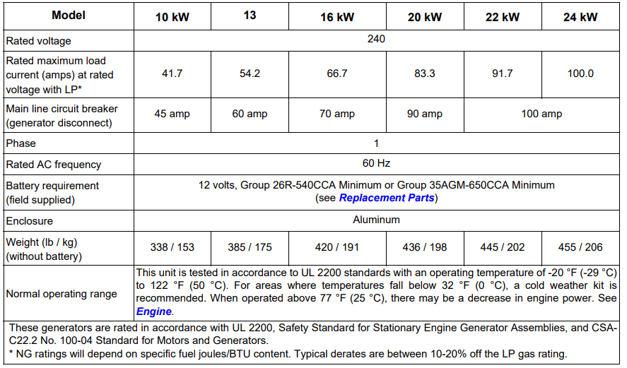
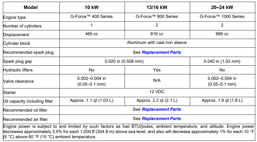
Specifications
Generator
Engine
Operation
Generator Enclosure
Enclosure lid is locked prior to shipment. A set of keys is attached to cardboard on top of generator. An additional set of keys is attached to pallet bracket on the front intake end of generator.
NOTE: Keys provided with this unit are intended for service personnel use only
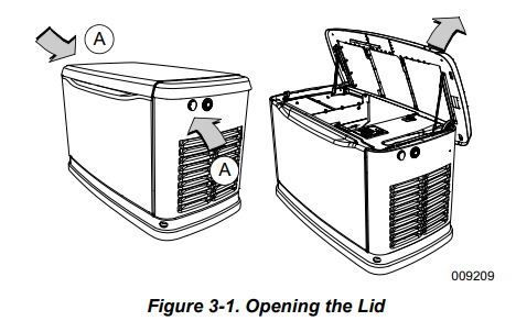
Opening the Lid
1. Use keys to open generator lid.
2. See Figure 3-1. Two locks (A) secure lid; one on each side. Open protective rubber cap to access keyhole.
3. Press down on lid above side lock, and unlock latch to correctly open lid.
4. Repeat for other side. Lid may appear stuck if pressure is not applied from the top.
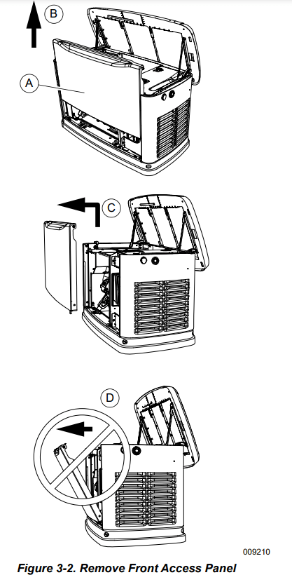
Front Access Panel Removal
See Figure 3-2. Remove front access panel (A) by lifting straight up and out once lid is open.
Intake Side Panel Removal
See Figure 3-3. Intake side panel (A) must be removed to access battery compartment, fuel regulator, and sediment trap.
1. Raise lid and remove front panel.
2. Use a hex key to remove two mounting screws (B) and L-bracket screw (C).
3. Lift intake panel up and away from generator.
NOTE: Always lift intake side panel straight up before pulling away from enclosure. Do not pull panel away from enclosure before lifting up (D).
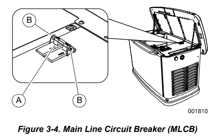
Main Line Circuit Breaker (Generator Disconnect)
See Figure 3-4. This is a 2-pole main line circuit breaker (MLCB) (generator disconnect) (A) rated according to relevant specifications.
The generator MLCB (generator disconnect) can be locked in OFF (OPEN) for security. Use an appropriatelysized padlock (not included) with a shackle long enough to pass through both lock tabs (B).
NOTE: DO NOT leave generator MLCB (generator disconnect) locked in OFF (OPEN) during normal generator operation. Leaving generator MLCB (generator disconnect) in OFF (OPEN) will prevent generator from powering structure during a power outage when placed in AUTO mode.
LED Indicator Lights
See Figure 3-5. Three LEDs are visible behind a translucent lens on the generator side panel. These LEDs indicate generator operating status.
• Green LED “Ready” light (A) illuminates when utility is present and control panel is in AUTO. LED flashes when automatic transfer switch converts to generator power during a utility power outage.
• Red LED “Alarm” light (B) illuminates when generator is OFF or a fault is detected. Contact an IASD.
• Yellow LED “Non-Critical Alert” light (C) illuminates when maintenance is required.
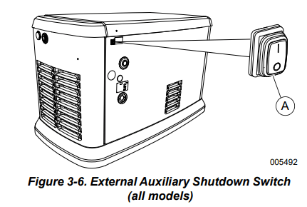
Auxiliary Shutdown Switch
All generators are equipped with an external means of shutting down the generator which complies with the latest NEC code requirement. Primary generator shutdown sequence is described in Shutting Generator Down While Under Load or During a Utility Outage.
See Figure 3-6. An auxiliary shutdown switch (A) is located on the exterior of the generator back panel. This auxiliary shutdown switch shuts down generator and disables restarts.
NOTE: Whenever possible, perform primary shutdown procedure before disabling generator with auxiliary shutdown switch.
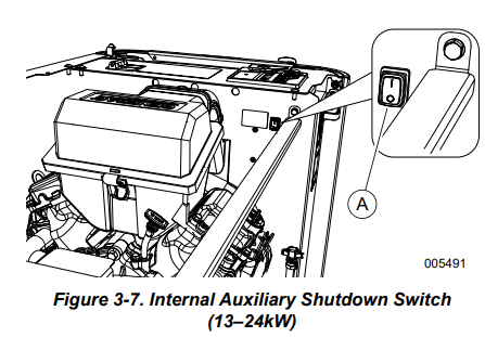
See Figure 3-7. 13–24 kW generators also have an auxiliary shutdown switch (A) located inside generator.
NOTE: Generator will not start if either switch is OPEN (O). Controller displays an “Auxiliary Shutdown” alarm, and red LED “Alarm” light illuminates. To clear this condition, set switch or switches to CLOSED (I). Clear alarm by pressing OFF button, and then ENTER. The generator can then be placed in AUTO or MANUAL.
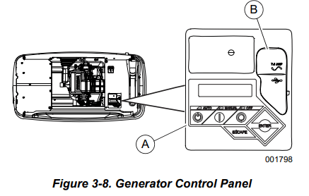
Control Panel Interface
See Figure 3-8. The control panel interface (A) is located under the enclosure lid. Verify both left and right side locks are unlocked before attempting to lift lid of enclosure. Open lid as directed in Opening the Lid.
The 7.5A fuse is located beneath rubber cover (B) to the right of the control panel.
Verify both left and right side locks are securely out of the way before closing unit.
All appropriate panels must be in place during any operation of the generator. This includes operation by a servicing technician while conducting troubleshooting procedures
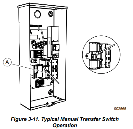
Manual Transfer Operation
Prior to automatic operation, manually exercise transfer switch to verify there is no interference with correct operation of the mechanism. Manual operation of transfer switch is required if electronic operation should fail
Transfer to Generator Power Source
1. Verify generator is in OFF mode.
2. Set generator MLCB (generator disconnect) to OFF (OPEN).
3. Turn off utility power supply to transfer switch using means provided (such as a utility MLCB).
4. See Figure 3-11. Use manual transfer handle (A) inside transfer switch to move main contacts to STANDBY (loads connected to standby power source).
5. Press MANUAL button on control panel to crank and start engine.
6. Allow engine to stabilize and warm up for a few minutes.
7. Set generator MLCB (generator disconnect) to ON (CLOSED). Standby power source now powers loads.
Transfer to Utility Power Source
Shut down generator and transfer to utility source after utility power has been restored. Proceed as follows to manually transfer to utility power and shut down generator:
1. Set generator MLCB (generator disconnect) to OFF (OPEN).
2. Run engine for one minute at no-load to stabilize internal temperature.
3. Press OFF button on control panel. Engine will shut down.
4. Verify utility power supply to transfer switch is turned off.
5. Set main contacts to UTILITY (loads connected to utility power source) using manual transfer handle inside transfer switch.
6. Turn on utility power supply to transfer switch using means provided (such as a utility MLCB).
7. Press AUTO button on control panel.
8. Set generator MLCB (generator disconnect) to ON (CLOSED).
9. Close and lock lid.
Automatic Transfer Operation
Proceed as follows to select automatic operation:
1. Verify transfer switch main contacts are set to UTILITY (loads connected to utility power source).
2. Verify normal utility power source voltage is available to loads connected to transfer switch.
3. Press AUTO button on control panel.
4. Set generator MLCB (generator disconnect) to ON (CLOSED).
Generator will start automatically when utility source voltage drops below a preset level. Loads are transferred to standby power source after unit starts.
Maintenance
Maintenance
Regular maintenance will improve performance and extend engine/equipment life. Generac Power Systems, Inc. recommends that all maintenance work be performed by an Independent Authorized Service Dealer (IASD). Regular maintenance, replacement, or repair of the emissions control devices and systems may be performed by any repair shop or person of the owner’s choosing. To obtain emissions control warranty service free of charge, the work must be performed by an IASD. See the emissions warranty.
Preparing for Maintenance
Proceed as follows to prepare unit for maintenance:
Set utility MLCB to OFF (OPEN).
Lift lid and set generator MLCB (generator disconnect) to OFF (OPEN).
If running during a utility outage, allow generator to run and cool down for one minute with no load.
Press OFF button on controller.
Remove 7.5A fuse from control panel.
Remove front panel and intake side panel.
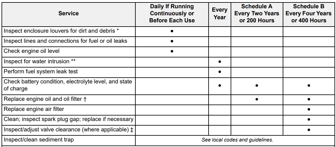
Performing Scheduled Maintenance
It is important to perform maintenance as specified in the Service Schedule for correct generator operation. Engine oil and oil filter must be changed, and valve clearance adjusted (where applicable, see Engine) after first 25 hours of operation.
Emissions-critical maintenance must be performed as scheduled in order for emissions warranty to be valid. Emissions-critical maintenance consists of servicing the air filter and spark plug(s) in accordance with Service Schedule.
Controller will prompt for Schedule A or Schedule B maintenance to be performed. Schedule A maintenance consists of oil, oil filter, and battery check. Schedule B maintenance includes oil, oil filter, battery check, air cleaner, spark plug(s), and valve clearance (where applicable, see Engine).
Since most maintenance alerts occur at the same time (most have two year intervals), only one will appear on control panel display at a time. Once first alert is cleared, the next active alert will be displayed.
Service Schedule
Contact the nearest IASD for assistance if necessary.
* Remove any shrubs or tall grasses which have grown within 3 ft (0.91 m) of intake and discharge louvers on enclosure sides. Clean any debris (dirt, grass clippings, etc.) which may have accumulated inside enclosure.
** Verify all sources of potential water intrusion such as water sprinklers, roof run-off, rain gutter downspouts, and sump pump discharges are directed away from generator enclosure.
† Change engine oil and filter after first 25 hours of operation. In cold weather conditions (ambient below 40 °F [4.4 °C]), or if unit is operated continuously in hot weather conditions (ambient above 85 °F [29.4 °C]), change engine oil and filter every year or 100 hours of operation.
‡ Inspect/adjust valve clearance after first 25 hours of operation. (Excludes units with hydraulic lifters. See Engine.)
Checking Engine Oil Level
Proceed as follows to check engine oil level:
Set utility MLCB to OFF (OPEN).
Set generator MLCB (generator disconnect) to OFF (OPEN).
Allow generator to run for a cool-down period of approximately one minute, if generator was running during an outage.
Press OFF button to turn generator off. Wait five minutes.
See Figure 2-1, Figure 2-2, or Figure 2-3. Remove oil dipstick and wipe it dry with a clean cloth.
Completely insert oil dipstick into oil dipstick tube and remove.
Observe oil level. Oil level should be at FULL mark on oil dipstick.
If necessary, remove oil fill cap and add recommended oil to engine (with oil dipstick removed) until oil level reaches FULL mark. Insert oil dipstick and install fill cap. See Engine Oil Requirements.
To restart generator:
Press AUTO button on control panel.
Allow generator to start and warm up for a few minutes. 3. Set generator MLCB (generator disconnect) to ON (CLOSED).
The system is now operating in AUTO. The utility MLCB can be turned ON (CLOSED)
Engine Oil Requirements
Engine oil should be serviced in accordance with the recommendations of this manual to maintain product warranty. Generac maintenance kits consisting of engine oil, oil filter, air filter, spark plug(s), a shop towel, and a funnel are available through an IASD.
All Generac oil kits meet minimum American Petroleum Institute (API) Service Class SJ, SL, or better. Do not use special additives.
Synthetic SAE 5W-30 for all temperature ranges. See Engine.
Changing the Oil and Oil Filter
Proceed as follows to change oil and oil filter:
1. Lift lid and press MANUAL button on control panel to start engine, and run unit until it is thoroughly warmed up. Press OFF button on control panel to shut down engine.
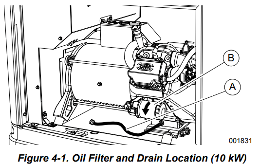
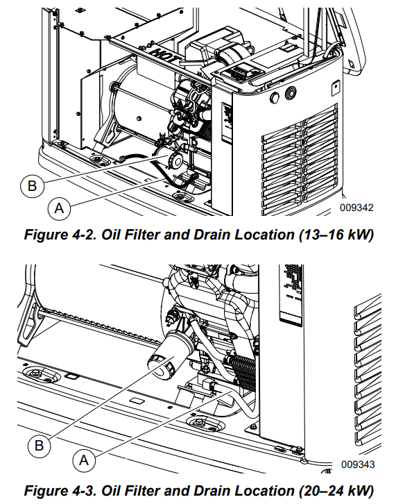
2. See Figure 4-1, Figure 4-2, or Figure 4-3. Remove front panel when unit has cooled. Pull oil drain hose (A) free of retaining clip. Remove cap from oil drain hose and place free end into a suitable container. Drain oil.
3. Install cap on oil drain hose. Position and secure oil drain hose with the retaining clip.
4. Remove oil filter (B) by turning it counterclockwise.
5. Apply a light coating of clean engine oil to gasket of new filter.
6. Screw new filter on by hand until gasket lightly contacts oil filter adapter. Tighten filter an additional three-quarter to one full turn.
7. Fill engine with recommended oil. See Engine Oil Requirements.
8. Press MANUAL button on control panel to start engine. Run for one minute, and inspect for leaks.
9. Press OFF button on control panel to stop engine. Wait five minutes.
10. Inspect oil level. Add oil as needed. DO NOT OVERFILL.
11. Insert oil dipstick and/or attach fill cap.
12. Press AUTO button on control panel to return unit to AUTO.
13. Close and lock lid.
14. Dispose of used oil and filter according to local, state, or national codes.
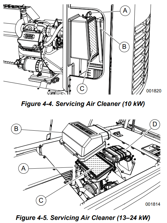
Servicing the Air Cleaner
Proceed as follows to service air cleaner:
1. Lift lid and press OFF button on control panel to stop generator.
2. Remove front panel.
3. See Figure 4-4 or Figure 4-5. Remove cover clips (A) and air cleaner cover (B).
4. Remove old air filter element (C) and discard.
5. Thoroughly clean air cleaner enclosure of any dust or debris.
6. Install a new air filter element.
7. Install air cleaner cover and fasten cover clips.
8. (13–24 kW units only): Verify air inlet duct (D) is correctly connected to air cleaner cover.
9. Press AUTO button on control panel to return unit to AUTO.
Spark Plug(s)
Proceed as follows to inspect spark plug gap(s) and replace spark plug(s) as necessary:
1. With generator OFF and engine cool, lift lid and remove front panel.
2. Clean area around base of spark plug(s) to keep dirt and debris out of engine.
3. Remove spark plug(s) and inspect. Install new spark plug(s) if existing spark plug(s) is worn, or if reuse is questionable.
4. Clean spark plug(s) by scraping or washing with a wire brush and commercial solvent. Do not blast spark plug(s) to clean.
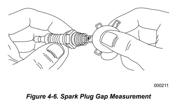
5. See Figure 4-6. Inspect spark plug gap(s) using a wire feeler gauge. Replace spark plug(s) if spark plug gap is out of specification. See General Information.
NOTE: New spark plug(s) should have spark plug gap checked prior to installation.
6. Install spark plug(s), and tighten to 18.4 ft-lbs (25 Nm).
7. Press AUTO button to return unit to AUTO mode.
Valve Clearance Adjustment
Inspect valve clearance after first 25 hours of operation, then after 400 hour intervals. Adjust if necessary
Checking Valve Clearance
NOTE: Engine should be cool before checking valve clearance. Adjustment is not needed if valve clearance is within dimensions provided in Engine.
Proceed as follows to check valve clearance.
1. Close fuel valve and disconnect battery to avoid accidental startup.
2. Remove spark plug wire(s), and position spark plug wire(s) away from spark plug(s).
3. Remove spark plug(s).
4. Remove the four screws attaching the valve cover. Remove and discard gasket. (Repeat for second cylinder, if equipped.)
5. Verify piston is at top dead center (TDC) of its compression stroke (both valves closed).
NOTE: To move piston to TDC, remove intake baffle at front of the engine to access the flywheel nut. Use a large socket and socket wrench to rotate flywheel nut clockwise, which will rotate the crankshaft. Watch piston through spark plug hole. Piston will move up and down. Piston is at TDC when at its highest point of travel.
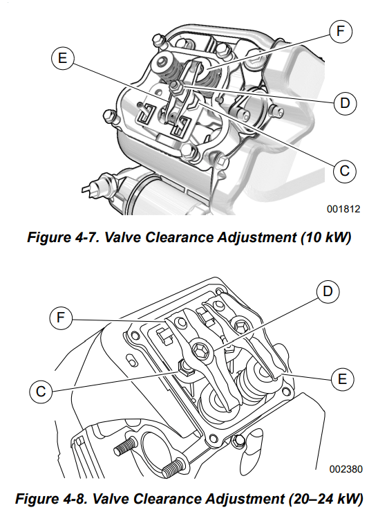
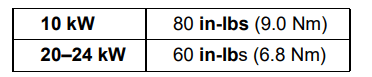
6. See Figure 4-7 or Figure 4-8. Verify valve clearance between each rocker arm (E) and valve stem (F) with a feeler gauge.
7. Install replacement valve cover gasket(s).
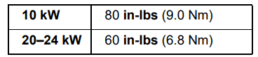
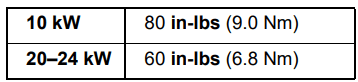
8. Install valve cover(s). Tighten fasteners in a cross pattern, tightening to:
Adjusting Valve Clearance
1. Remove spark plug wire(s) and position spark plug wire(s) away from spark plug(s).
2. Remove spark plug(s).
3. Remove the four screws attaching valve cover. Remove and discard gasket.
4. Verify piston is at TDC of its compression stroke (both valves closed).
5. Loosen rocker jam nut (C) using a 10 mm wrench (10 kW units) or 13 mm wrench (20–24 kW units).
6. Turn pivot ball stud (D) using a 14 mm wrench (10 kW units), or 10 mm hex key (20–24 kW units) while inspecting clearance between rocker arm (E) and valve stem (F) with a feeler gauge. Adjust clearance as per Engine.
NOTE: Hold rocker jam nut in place as pivot ball stud is turned.
7. When valve clearance is correct, hold pivot ball stud in place with a wrench and tighten rocker arm jam nut. Tighten jam nut according to:
8. Inspect valve clearance to verify it did not change.
9. Install new valve cover gasket.
10. Install valve cover. Tighten fasteners in a cross pattern. Tighten to:
11. Install spark plug(s) and tighten to 18 ft-lbs (25 Nm).
12. Attach spark plug wire(s) to spark plug(s).
13. Repeat process for other cylinder if equipped.
Battery Maintenance
Always recycle batteries in accordance with local laws and regulations. Contact your local solid waste collection site or recycling facility to obtain information on local recycling processes.
Strictly observe the following precautions when working on batteries:
• Remove 7.5A fuse from generator control panel.
• Disconnect battery charger as directed in Inspecting the Battery.
• Use tools with insulated handles.
• Wear rubber gloves and boots.
• Do not place tools or metallic objects on top of battery.
• Disconnect charging source prior to connecting or disconnecting battery terminals.
• Wear full eye protection and protective clothing.
• If electrolyte contacts skin, wash it off immediately with water.
• If electrolyte contacts eyes, flush thoroughly with water immediately and seek medical attention.
• Wash down spilled electrolyte with an acid neutralizing agent. A common practice is to use a solution of 1 lb (454 g) bicarbonate of soda to 1 gal (3.8 L) of water. Add bicarbonate of soda solution until evidence of reaction (foaming) has ceased. Flush resulting liquid with water and dry area completely.
• DO NOT smoke near battery.
• DO NOT cause flame or spark in battery area.
• Discharge static electricity from the body before touching battery by first touching a grounded metal surface.
Battery should be regularly inspected per Service Schedule. Contact an IASD for assistance if necessary
Inspecting the Battery
Proceed as follows to inspect battery:
1. Press OFF button to shut down generator, then lift lid and remove front panel.
2. Remove 7.5A fuse from control panel.
3. Remove intake side panel. (See Intake Side Panel Removal.)
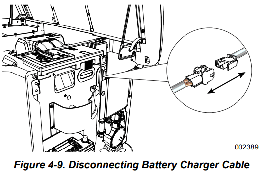
4. See Figure 4-9. Disconnect white battery charger cable.
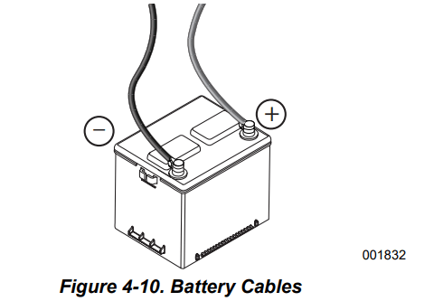
5. See Figure 4-10. Inspect battery posts and cables for tightness and corrosion. Tighten and clean as necessary
6. Unsealed batteries only: Completely disconnect battery, removing negative battery cable first. Check battery fluid level and, if necessary, fill with distilled water only. DO NOT use tap water. Have an IASD or a qualified service technician verify state of charge and condition.
7. Connect positive battery cable, then negative battery cable.
8. Connect battery charger cable.
9. Install intake side panel, and install 7.5 A fuse. 10. Press AUTO button on controller.
11. Install front panel and close generator lid.
Cleaning the Sediment Trap
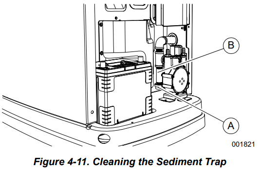
The sediment trap removes contaminants (moisture and fine particles) from gaseous fuels before they enter the fuel regulator. Accumulated moisture and particles must be emptied from the sediment trap per local codes and guidelines. Proceed as follows to clean sediment trap:
1. Remove intake side panel. See Intake Side Panel Removal.
2. Turn generator fuel supply OFF.
3. See Figure 4-11. Unscrew and remove cap (A).
4. Use a clean-out tool (not provided) to remove accumulated moisture and particles from cap and body (B).
5. Wipe inside of each component with a clean, dry, lint-free cloth.
6. Seal threads of cap with appropriate sealing compound. Install cap and hand-tighten.
7. Tighten cap with an appropriately sized pipe wrench. DO NOT overtighten.
8. Turn generator fuel supply ON. Inspect for leaks by spraying all connection points with a non-corrosive gas leak detection fluid. Solution should not be blown away or form bubbles.
9. Install intake side panel.
Post Maintenance Checks
Proceed as follows to perform post maintenance checks:
1. Perform required maintenance procedure(s).
2. Install intake side panel and front panel if removed. (See Intake Side Panel Removal and Front Access Panel Removal.)
3. Install 7.5A fuse in control panel.
4. Complete Install Wizard information.
5. Press AUTO button on control panel. Allow unit to run for one minute with no load (if running during a utility outage).
6. Set generator MLCB (generator disconnect) to ON (CLOSED).
7. Set utility MLCB to ON (CLOSED).
The system is now in AUTO.
NOTE: If correct utility is present at this time, generator will perform its usual shutdown process.
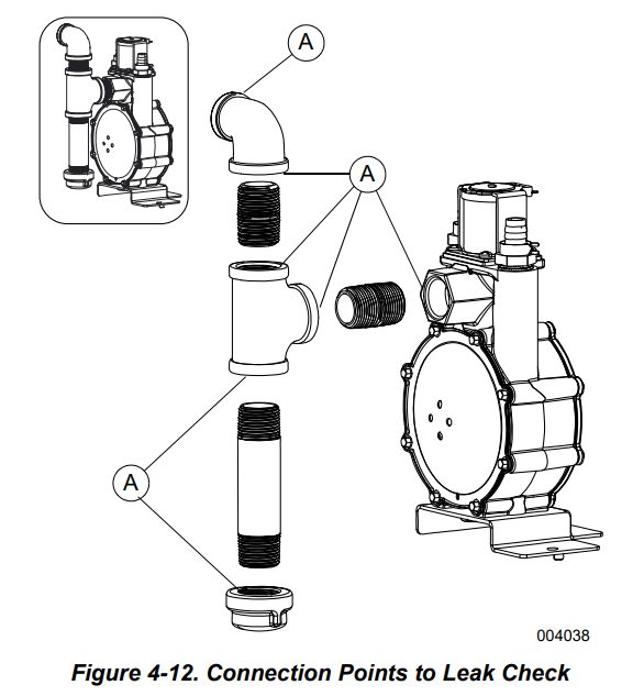
Performing Fuel System Leak Test
All products are factory-tested before shipping to verify the performance and integrity of the fuel system. However, it is important to perform a final fuel system leak test before starting the generator. The entire fuel system should be tested from supply to regulator.
See Figure 4-12. Perform a final fuel system leak test after generator installation. The test will identify possible leaks at all connection points (A).
It is best practice to perform a fuel system leak test during normally-scheduled maintenance.
Inspect for leaks by spraying all connection points with a non-corrosive gas leak detection fluid. The solution should not be blown away or form bubbles.
Attention After Submersion
DO NOT start or operate generator if it has been submerged in water. Have an IASD thoroughly clean, dry, and inspect generator following any submersion in water. If the structure (home) has been flooded, it should be inspected by a certified electrician to verify there will not be any electrical problems during generator operation or when utility power is returned.
Corrosion Protection
Regular scheduled maintenance should be conducted to inspect unit for corrosion. Inspect all metal components of generator, including base frame, brackets, alternator can, the entire fuel system (inside and outside of the generator), and fastener locations. If there is corrosion found on generator components (e.g. regulator, engine/alternator mounts, fuel plenum, etc.), replace parts as necessary.
Periodically wash and wax enclosure using automotive type products. Do not spray unit with a hose or power washer. Use warm, soapy water and a soft cloth. Frequent washing is recommended in salt water/coastal areas. Spray engine linkages with a light oil such as WD40.
Remove From and Return To Service Procedure
Remove From Service
If generator cannot be exercised monthly, at a minimum, and will be out of service longer than 90 days, proceed as follows to prepare generator for storage:
Start engine and allow it to warm up.
Close fuel shutoff valve in fuel supply line and allow engine to stop.
Set generator MLCB (generator disconnect) to OFF (OPEN) once engine has stopped.
Disconnect battery charger AC input T1/Neutral cable (with white sleeve) at controller.
Drain oil completely while engine is still warm, and then fill crankcase with oil. See Changing the Oil and Oil Filter.
Attach a tag to engine indicating viscosity and classification of the new oil in the crankcase.
Remove spark plug(s) and spray a fogging agent into spark plug(s) threaded openings. Install and tighten spark plug(s) to specification.
Remove battery and store in a cool, dry place.
Clean and wipe down generator enclosure.
Return to Service
Proceed as follows to return unit to service after storage:
Inspect engine tag for oil viscosity and classification. Drain and fill with recommended oil if necessary.
Verify state of battery. Fill all cells of unsealed batteries to correct level with distilled water. DO NOT use tap water. Charge battery to 100% state of charge. Replace battery if faulty.
Clean and wipe down generator enclosure.
Verify 7.5A fuse is removed from generator control panel.
Connect battery. Observe battery polarity. Damage will occur if battery is connected incorrectly. Install positive battery cable first
Connect battery charger AC input T1/Neutral cable (with white sleeve) at controller.
Open fuel shutoff valve
Insert 7.5 A fuse into generator control panel.
Complete Install Wizard procedure (diagrammed in generator installation manual).
Press MANUAL button to start unit. Allow unit to warm up for a few minutes.
Press OFF button to stop unit.
Set generator MLCB (generator disconnect) to ON (CLOSED).
Press AUTO button on control panel.
The generator is ready for service.
NOTE: Exercise timer and current date and time must be reset if battery is discharged or has been disconnected.
Troubleshooting / Quick Reference Guide
Generator Troubleshooting
Problem
Cause
Correction
Engine will not crank
Blown fuse.
Correct short circuit condition by replacing 7.5 A fuse in generator control panel. Contact an IASD if fuse continues to blow.
Loose, corroded, or faulty battery cables.
Faulty starter contact.
Faulty starter motor.
Tighten, clean, or replace as necessary.*
Discharged battery
Charge or replace battery.
Engine cranks but will not start
No fuel.
Replenish fuel / turn on fuel valve.
Faulty fuel solenoid (FS).
Harness/wiring issue.
Contact an IASD for assistance.
Faulty spark plug(s).
Clean; inspect spark plug gap; replace spark plug(s) if necessary.
Valve clearance out of adjustment, if applicable. See Engine.
Inspect and adjust valve clearance.
Engine starts hard and runs rough
Plugged or damaged air cleaner.
Inspect and clean air cleaner.
Faulty spark plug(s).
Clean; inspect spark plug gap; replace spark plug(s) if necessary.
Incorrect fuel pressure.
Verify fuel pressure to regulator is 10–12 in water column (2.49–2.99 kPa) for LP gas, and 3.5–7.0 in water column (0.87–1.74 kPa) for NG
Fuel selector in wrong position.
Set fuel conversion valve to correct position and program controller for fuel type.
Valve clearance out of adjustment, if applicable. See Engine.
Inspect and adjust valve clearance
Internal engine issue.
Contact an IASD for assistance.
Unit is set to OFF, but engine continues to run
Controller wired incorrectly.
Faulty control board.
Contact an IASD for assistance.
No AC output from generator
Generator MLCB (generator disconnect) is OFF (OPEN).
Set generator MLCB (generator disconnect) to ON (CLOSED).
Generator internal failure.
Contact an IASD for assistance.
Engine may be warming up. See Cold Smart Start. .
Check the controller screen to verify status
No transfer to standby after utility source failure
Generator MLCB (generator disconnect) is OFF (OPEN).
Set generator MLCB (generator disconnect) to ON (CLOSED).
Faulty transfer switch coil.
Faulty transfer relay.
Transfer relay circuit open.
Faulty control logic board.
Contact an IASD for assistance.
Engine may be warming up. See Cold Smart Start.
Check controller screen to verify status.
Unit consumes large amounts of oil
Excessive engine oil.
Adjust oil to correct level. See Checking Engine Oil Level.
Faulty engine breather.
Contact an IASD for assistance.
Incorrect type or viscosity of oil.
See Engine Oil Requirements.
Damaged gasket, seal, or hose.
Inspect for oil leaks.
Restricted air filter.
Replace air filter.
Wi-Fi network connection broken or intermittent
Various.
See Wi-Fi module owner’s manual.
Quick Reference Guide
To clear an active alarm, press OFF button on the control panel, then the ENTER button, and finally the AUTO button. Contact an IASD if alarm reoccurs.
Active Alarm
LED
Problem
Action
Solution
NONE
FLASHING GREEN
Unit running in AUTO but no power in house.
Check generator MLCB (generator disconnect)
Check generator MLCB (generator disconnect). If it is ON, contact an IASD.
HIGH TEMPERATURE
RED
Unit shuts down during operation.
Check LEDs / screen for alarms
Inspect ventilation around generator, intake, exhaust, and rear of generator. If no obstructions are present, contact an IASD
OVERLOAD REMOVE LOAD
RED
Unit shuts down during operation.
Check LEDs / screen for alarms.
Clear alarm and remove household loads from generator. Put in AUTO and restart.
RPM SENSE LOSS
RED
Unit was running and shut down, attempts to restart.
Check LEDs / screen for alarms.
Clear alarm and remove household loads from generator. Put into AUTO and restart. If generator does not start, contact an IASD.
NOT ACTIVATED
NONE
Unit will not start in AUTO with utility loss.
Check if screen says unit not activated.
See Activation section in installation manual.
NONE
GREEN
Unit will not start in AUTO with utility loss.
Check screen for start delay countdown.
If startup delay is greater than expected, contact an IASD to adjust from 2 to 1500 seconds.
LOW OIL PRESSURE
RED
Unit will not start in AUTO with utility loss.
Check LEDs / screen for alarms.
Check oil level and add oil as needed. If oil level is correct, contact an IASD
RPM SENSE LOSS
RED
Unit will not start in AUTO with utility loss.
Check LEDs / screen for alarms.
Clear alarm. Using control panel, check battery by navigating to BATTERY MENU option from MAIN MENU. If battery condition displays GOOD, contact an IASD. If control panel displays CHECK BATTERY, replace battery
OVERCRANK
RED
Unit will not start in AUTO with utility loss.
Check LEDs / screen for alarms
Verify fuel line shutoff valve is ON. Clear alarm. Start unit in MANUAL. If it does not start, or starts and runs rough, contact an IASD.
LOW VOLTS REMOVE LOAD
RED
Unit will not start in AUTO with utility loss.
Check LEDs / screen for alarms
Clear alarm and remove household loads from generator. Put in AUTO and restart.
OVERSPEED
RED
Unit will not start in AUTO with utility loss.
Check LEDs / screen for alarms
Contact an IASD.
UNDERVOLTAGE
RED
Unit will not start in AUTO with utility loss.
Check LEDs / screen for alarms
Contact an IASD.
UNDERSPEED
RED
Unit will not start in AUTO with utility loss.
Check LEDs / screen for alarms
Contact an IASD.
STEPPER OVERCURRENT
RED
Unit will not start in AUTO with utility loss.
Check LEDs / screen for alarms
Contact an IASD.
WIRING ERROR
RED
Unit will not start in AUTO with utility loss.
Check LEDs / screen for alarms
Contact an IASD.
OVERVOLTAGE
RED
Unit will not start in AUTO with utility loss.
Check LEDs / screen for alarms
Contact an IASD.
AUXILIARY SHUTDOWN
RED
Unit will not start.
Check auxiliary shutdown switches
Set auxiliary shutdown switch(es) to CLOSED (I). Clear alarm
LOW BATTERY
YELLOW
Yellow LED illuminated in any state.
Check screen for additional information
Clear alarm. Using control panel, check battery by navigating to BATTERY MENU option from MAIN MENU. If battery condition displays GOOD, contact an IASD. If control panel displays CHECK BATTERY, replace battery
BATTERY PROBLEM
YELLOW
Yellow LED illuminated in any state.
Check screen for additional information
Contact an IASD.
CHARGER WARNING
YELLOW
Yellow LED illuminated in any state.
Check screen for additional information
Contact an IASD.
CHARGER MISSING AC
YELLOW
Yellow LED illuminated in any state.
Check screen for additional information
Contact an IASD.
SERVICE A
YELLOW
Yellow LED illuminated in any state.
Check screen for additional information
Perform SERVICE A maintenance. Press ENTER to clear.
SERVICE B
YELLOW
Yellow LED illuminated in any state.
Check screen for additional information
Perform SERVICE B maintenance. Press ENTER to clear.
The sound output for Generac model #7209 in dB(A) at 23 ft with generator operating at normal load is 67. The sound output in dB(A) at 23 ft with generator in Quiet-Test at low-speed exercise model is 57.
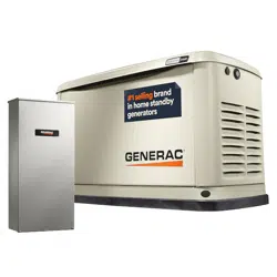
Installations will vary depending on the home, but an average installation will include installation of a mounting pad, wiring, and gas connections. The cost of the installation will vary depending upon the layout of your home and the gas line set-up necessary. We recommend working with an authorized Generac installer who can provide a quote for the cost of installation.
#4 Does it automatically lock out PG&E when it comes on. And then turn off when PG&E comes back on.
Yes, the generator can sense when utility power is shut off, but will also turn off once power is restored.