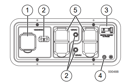
120/240 Volt AC, 30 Amp Locking Receptacle (NEMA L14-30R)
Circuit Breakers (AC)
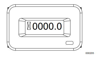
Hour Meter
Battery Charger Input
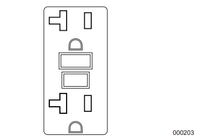
Volt AC, 20 Amp, GFCI Duplex Receptacle (NEMA 5-20R)
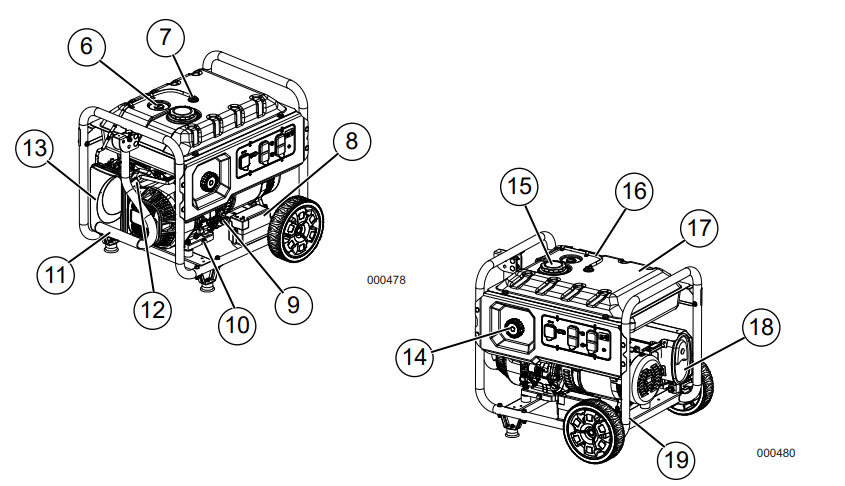
Fuel Gauge
Roll Over Valve
Battery Location
Oil Check/Fill
Oil Drain
Handle
Recoil Starter
Air Filter
PowerDial
Fuel Cap
Recovery Hose
Fuel Tank
Muffler
Grounding Lug
Figure 2-2. Control Panel (49 State)
Figure 2-3. Unit Identification Label
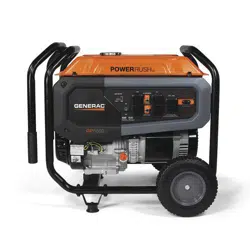
Know Your Generator
WARNING Consult Manual. Read and understand manual completely before using product. Failure to completely understand manual and product could result in death or serious injury.
Emissions
The United States Environmental Protection Agency (US EPA) (and California Air Resources Board (CARB), for engines/equip ment certified to California standards) requires that this engine/equipment complies with exhaust and evaporative emissions standards. Locate the emissions compliance decal on the engine to determine applicable stan dards. For emissions warranty information, please reference the included emissions war ranty. It is important to follow the maintenance specifications in the manual to ensure that the engine complies with the applicable emissions standards for the duration of the product’s life.
Product Specifications
Generator Specifications
Rated Power @1.0 Power Factor
8.0 kW**
Surge Power
10.0 KVA
Rated AC Voltage
120/240
Rated AC Load
Current @ 240V**
Current @ 120V**
33.3
66.6
Rated Frequency
60 Hz @ 3600 RPM
Phase
Single Phase
Weight (dry)
Pounds (lb)
Kilograms (kg)
213.8
97
** Operating Temperature Range: -18 deg. C (0 deg. F) to 40 Deg. C (104 Deg. F). When operated above 25 deg. C (77 deg. F) there may be a decrease in power.
** Maximum wattage and current are subject to, and limited by, such factors as fuel Btu content, ambi ent temperature, altitude, engine condition, etc. Maximum power decreases about 3.5% for each 1,000 feet above sea level; and will also decrease about 1% for each 6° C (10° F) above 16° C (60° F) ambient temperature.
Engine Specifications
Displacement
420cc
Spark Plug Part No.
0J00620106
Spark Plug Gap
0.028-0.031 inch or (0.70-0.80 mm)
Gasoline Capacity
30 L (8 gal)
Oil Type
See Chart in Add Engine Oil
Oil Capacity
1.0 L (1.06 qt.)
Run Time at 50% Load
10.5 Hours
Hour Meter
The Hour Meter tracks hours of operation for scheduled maintenance. See Figure 2-4.
The CHG OIL display will illuminate every 100 hours. The message will flash one hour before and one hour after each 100 hour interval, providing a two hour window to perform service.
The SVC display will illuminate every 100 hours. The message will flash one hour before and one hour after each 200 hour
interval providing a two hour window to per form service. When the hour meter is in flash alert mode, the maintenance message will alternate with elapsed time in hours and tenths. The hours will flash four times, then alternate with the maintenance message four times until the meter automatically resets.
100 hours - CHG OIL — Oil Change Inter val (Every 100 hrs)
200 hours - SVC — Service Air Filter (Every 200 hrs)
NOTE: The hour glass icon will flash when the engine is running. This signifies the meter is recording hours of operation.
Figure 2-4. Hour Meter
Connection Plugs
120 VAC, 20 Amp, GFCI Duplex Receptacle
The 120 Volt outlet is overload protected by a 20 Amp push-to-reset circuit breaker. See Fig ure 2-5. Each receptacle will power 120 Volt AC, single phase, 60 Hz electrical loads requiring up to 2400 watts (2.4 kW) or 20 Amps of current. Use only high quality, well insulated, 3-wire grounded cord sets rated for 125 Volts at 20 Amps (or greater). It also pro vides protection with a Ground Fault Circuit Interrupter with a press to TEST and RESET button.
Use a NEMA L14-30 plug with this receptacle (rotate to lock/unlock). Connect a suitable 4- wire grounded cord set to plug and desired load. The cord set should be rated 250 Volts AC at 30 Amps (or greater). See Figure 2-6.
Use this receptacle to operate 120 Volt AC, 60 Hz, single phase loads requiring up to 3600 watts (3.6 kW) of power at 30 Amps or 240 Volt AC, 60 Hz, single phase loads requiring up to 7200 watts (7.2 kW) of power at 30 Amps. The outlet is protected by one 30 Amp 2-pole circuit breaker.
Figure 2-6. 120/240 VAC, 30 Amp Receptacle NEMA L14-30R
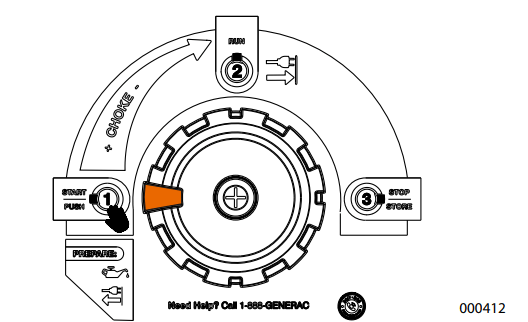
PowerDial
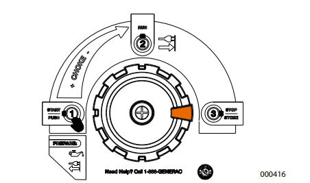
The PowerDial controls the ON/OFF functions, choke and fuel valve operation. See Figure 2-7.
The Number 1 position is used when ini tially starting the engine. In this position, the fuel is on and the choke is fully ON (closed). Both the electric start or pull (recoil) start can be used.
The PowerDial is rotated to position Number 2 during normal operation and to gradu ally reduce the use of the choke.
Rotating the PowerDial to the STOP position will stop the engine and shut off the fuel valve flow.
Figure 2-7. PowerDial (example)
Remove Contents from Carton
1. Open carton completely by cutting each corner from top to bottom.
2. Remove and verify carton contents prior to assembly. Carton contents should contain the following:
Accessories
Item
Qty.
Main Unit
1
Owner’s Manual
1
Liter Oil SAE 30
1
Handle Assembly (A)
1
Never-flat Wheel (B)
2
Frame Foot (C)
2
Product Registration Card
3
Service Warranty
1
Emissions Warranty
1
25’ Power Cord (if equipped)
1
Battery Charger (electric start models)
1
Hardware Bag
Qty.
Rubber Feet (D)
2
1/2” Axle Pin (E)
2
Cotter Pin (F)
2
1/2” Flat Washer (G)
2
Hex Flanged M6 Nut (H)
2
Hex Flanged M8 Nut (J)
5
M8 Bolt (Long) (K)
6
M6 Bolt (Long) (L)
1
M8 Nylon Flat Washer (M)
4
3. Call Generac Customer Service 1-888- GENERAC (1-888-436-3722) with the unit model and serial number for any missing carton contents.
4. Record model, serial number, and date of purchase on front cover of this manual.
Assembly
WARNING
Consult Manual. Read and understand manual completely before using product. Failure to completely understand manual and product could result in death or serious injury.
Call Generac Customer Service at 1-888- GENERAC (1-888-436-3722) for any assem bly issues or concerns. Please have model and serial number available.
The following tools are required to install the accessory kit.
Needle Nose Pliers
Ratchet Wrench
8mm Socket
12mm Socket
13mm Socket
10mm Wrench
13mm Wrench
8mm Wrench (2) (electric start only)
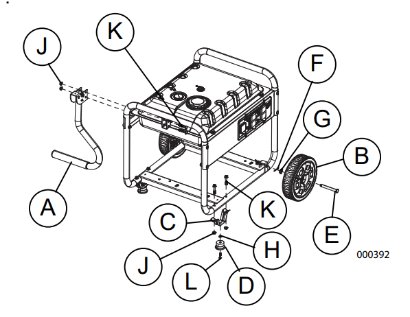
NOTE: The wheels are not intended for over the-road use.
See Figure 2-8.
Install wheels as follows:
1. Slide axle pin (E) through the wheel (B), wheel bracket on frame, and 1/2” flat washer (G).
2. Insert cotter pin (F) through axle pin (E). Bend tabs (of cotter pins) outward to lock into place.
Install frame foot and rubber bumpers as fol lows:
1. Slide hex head bolts (L) through rubber bumper (D), then through frame foot (C).
2. Slide hex head bolts (K) through holes in frame rail.
1. Slide long bolts (K) through handle bracket and handle (A). Install hex nuts (J). .
Figure 2-8. Wheel, Frame Foot and Handle Assembly
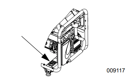
Battery Cable Connection
NOTE: The battery shipped with the generator has been fully charged. A battery may lose some charge when not in use for prolonged periods of time. If battery is unable to crank engine, plug in the 12V charger included in the accessory box. See Charging the Battery.
IMPORTANT NOTE: Running the generator does not charge battery. WARNING
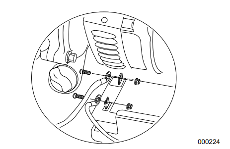
Accidental Start-up. Disconnect the negative battery cable, then the positive battery cable when working on unit. Failure to do so could result in death or serious injury. See Figure 2-9. Use two 8mm wrenches to tighten battery hardware.
1. Disconnect negative (-) battery terminal FIRST (black wire).
2. Disconnect positive (+) battery terminal SECOND (red wire).
Figure 2-9. Battery Connection
Add Engine Oil
CAUTION
Engine damage. Verify proper type and quantity of engine oil prior to starting engine. Failure to do so could result in engine damage.
1. Place generator on a level surface.
2. Verify oil fill area is clean.
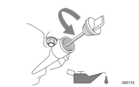
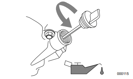
3. Remove oil fill cap and wipe dipstick clean. See Figure 2-10.
Figure 2-10. Remove Dipstick
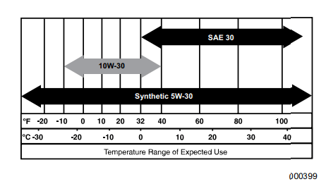
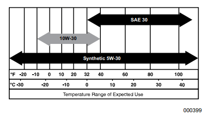
4. Add recommended engine oil as shown in the following chart.
NOTE: Use petroleum based oil (supplied) for engine break-in before using synthetic oil.
NOTE: Some units have more than one oil fill location. It is only necessary to use one oil fill point.
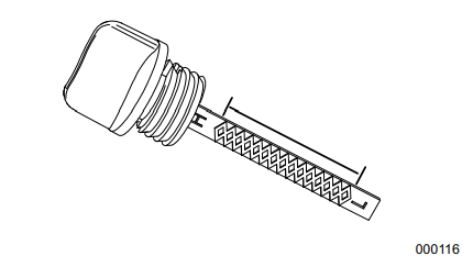
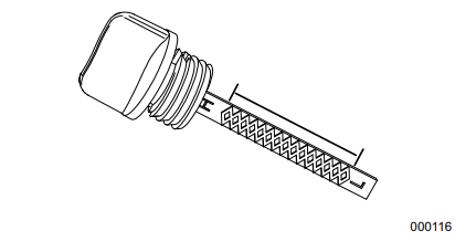
5. Thread dipstick into oil filler neck. Oil level is checked with dipstick fully installed.
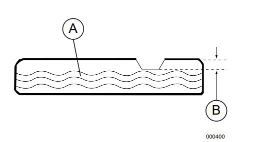
6. See Figure 2-11. Remove dipstick and ver ify oil level is within safe operating range.
Figure 2-11. Safe Operating Range
7. Install oil fill cap/dipstick and hand-tighten.
Fuel
DANGER
Explosion and Fire. Fuel and vapors are extremely flammable and explosive. Add fuel in a well ventilated area. Keep fire and spark away. Failure to do so will result in death or serious injury.
WARNING
Fluid Injection. This machine produces high-pressure fluid streams that can pierce skin. Fluid injection could result in death or serious injury.
Fuel requirements are as follows:
Clean, fresh, unleaded gasoline.
Minimum rating of 87 octane/87 AKI (91 RON).
Up to 10% ethanol (gasohol) is acceptable (where available; non-ethanol-premium fuel is recommended).
DO NOT use E85.
DO NOT use a gas oil mix.
DO NOT modify engine to run on alternate fuels. Stabilize fuel prior to storage.
1. Verify unit is OFF and cooled for a mini mum of two minutes prior to fueling.
2. Place unit on level ground in a well venti lated area.
3. Clean area around fuel cap and remove cap slowly.
4. Slowly add recommended fuel (A). Do not overfill (B). See Figure 2-12.
5. Install fuel cap.
Figure 2-12. Add Recommended Fuel
NOTE: Allow spilled fuel to evaporate before starting unit.
IMPORTANT NOTE: It is important to pre vent gum deposits from forming in fuel system parts such as the carburetor, fuel hose or tank during storage. Alcohol blended fuels (called gasohol, ethanol or methanol) can attract moisture, which leads to separation and formation of acids during storage. Acidic gas can damage the fuel system of an engine while in storage. To avoid engine problems, the fuel system should be emptied before storage of 30 days or longer. See the Storage section. Never use engine or carburetor cleaner products in the fuel tank as permanent damage may occur.
Operation
Operation and Use Questions
Call Generac customer service at 1-888-GEN ERAC (1-888-436-3722) with questions or concerns about equipment operation and maintenance.
Before Starting Engine
1. Verify engine oil level is correct.
2. Verify fuel level is correct.
3. Verify unit is secure on level ground, with proper clearance and is in a well ventilated area.
Prepare Generator for Use
DANGER
Asphyxiation. Running engines produce carbon monoxide, a colorless, odorless, poisonous gas. Carbon monoxide, if not avoided, will result in death or serious injury.
WARNING
Asphyxiation. Always use a battery operated carbon monoxide alarm indoors and installed according to the manufacturer’s instructions. Failure to do so could result in death or serious injury
DANGER
Asphyxiation. The exhaust system must be properly maintained. Do not alter or modify the exhaust system as to render it unsafe or make it noncompliant with local codes and/or standards. Failure to do so will result in death or serious injury.
WARNING
Risk of Fire. Hot surfaces could ignite combustibles, resulting in fire. Fire could result in death or serious injury.
Risk of fire. Do not use generator without spark arrestor installed. Failure to do so could result in death or serious injury.
WARNING
Hot Surfaces. When operating machine, do not touch hot surfaces. Keep machine away from combustibles during use. Hot surfaces could result in severe burns or fire.
Grounding the Generator When Used as a Portable
The generator is equipped with an equipment ground connecting the generator frame and the ground terminals on the AC output recep tacles (see NEC 250.34 (A). This allows the generator to be used as a portable without grounding the frame of the generator as spec ified in NEC 250.34. See Figure 3-1.
Neutral Bonded to Frame.
Figure 3-1. Grounding the Generator
Special Requirements
Review all Federal or State Occupational Safety and Health Administration (OSHA) reg ulations, local codes, or ordinances that apply to the intended use of the generator. Consult a qualified electrician, electrical inspector, or the local agency having jurisdiction:
In some areas, generators are required to be registered with local utility companies.
If the generator is used at a construction site, there may be additional regulations which must be observed.
Connecting the Generator to a Building Electrical System
It is recommended to use a manual transfer switch when connecting directly to a building electrical system. Connecting a portable gen erator to a building electrical system must be made in strict compliance with all national and local electrical codes and laws, and be com pleted by a qualified electrician.
Know Generator Limits
Overloading a generator can result in damage to the generator and connected electrical devices. Observe the following to prevent overload:
Add up the total wattage of all electrical devices to be connected at one time. This total should NOT be greater than the gener ator's wattage capacity.
The rated wattage of lights can be taken from light bulbs. The rated wattage of tools, appliances, and motors can be found on a data label or decal affixed to the device.
If the appliance, tool, or motor does not give wattage, multiply volts times ampere rating to determine watts (volts x amps = watts).
Some electric motors, such as induction types, require about three times more watts of power for starting than for running. This surge of power lasts only a few seconds when starting such motors. Make sure to allow for high starting wattage when select ing electrical devices to connect to the gen erator:
1. Figure the watts needed to start the largest motor.
2. Add to that figure the running watts of all other connected loads.
The Wattage Reference Guide is provided to assist in determining how many items the gen erator can operate at one time.
NOTE: All figures are approximate. See data label on appliance for wattage requirements.
Wattage Reference Guide
Device
Running Watts
*Air Conditioner (12,000 Btu)
1700
*Air Conditioner (24,000 Btu)
3800
*Air Conditioner (40,000 Btu)
6000
Battery Charger (20 Amp)
500
Belt Sander (3")
1000
Chain Saw
1200
Circular Saw (6-1/2")
800 to 1000
*Clothes Dryer (Electric)
5750
*Clothes Dryer (Gas)
700
*Clothes Washer
1150
Coffee Maker
1750
*Compressor (1 HP)
2000
*Compressor (3/4 HP)
1800
*Compressor (1/2 HP)
1400
Curling Iron
700
*Dehumidifier
650
Disc Sander (9")
1200
Edge Trimmer
500
Electric Blanket
400
Electric Nail Gun
1200
Electric Range (per element)
1500
Electric Skillet
1250
*Freezer
700
*Furnace Fan (3/5 HP)
875
*Garage Door Opener
500 to 750
Hair Dryer
1200
Hand Drill
250 to 1100
Hedge Trimmer
450
Impact Wrench
500
Iron
1200
*Jet Pump
800
Lawn Mower
1200
Light Bulb
100
Microwave Oven
700 to 1000
*Milk Cooler
1100
Oil Burner on Furnace
300
Oil Fired Space Heater (140,000 Btu)
400
Oil Fired Space Heater (85,000 Btu)
225
Oil Fired Space Heater (30,000 Btu)
150
*Paint Sprayer, Airless (1/3 HP)
600
Paint Sprayer, Airless (hand-held)
150
Radio
50 to 200
*Refrigerator
700
Slow Cooker
200
*Submersible Pump (1-1/2 HP)
2800
*Submersible Pump (1 HP)
2000
*Submersible Pump (1/2 HP)
1500
*Sump Pump
800 to 1050
*Table Saw (10")
1750 to 2000
Television
200 to 500
Toaster
1000 to 1650
Weed Trimmer
500
* Allow 3 times the listed watts for starting these devices.
Transporting/Tipping of the Unit
Do not operate, store or transport the unit at an angle greater than 15 degrees.
Starting Pull Start Engines
WARNING
Recoil Hazard. Recoil could retract unexpectedly. Kickback could result in death or serious injury.
CAUTION
Equipment and property damage. Disconnect electrical loads prior to starting or stopping unit. Failure to do so could result in equipment and property damage.
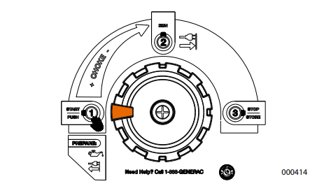
1. See Figure 3-2. Rotate the PowerDial to START.
.
Figure 3-2. PowerDial START Position
2. Firmly grasp recoil handle and pull slowly until increased resistance is felt. Pull rap idly up and away.
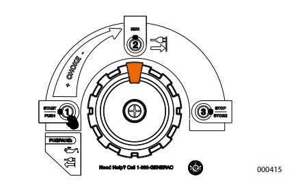
3. See Figure 3-3. When engine starts, rotate PowerDial to RUN. Choke operation is reduced as PowerDial is rotated towards RUN. If engine falters, rotate PowerDial counterclockwise to START to increase choke. When engine runs smoothly, rotate back to RUN.
Figure 3-3. PowerDial RUN Position
NOTE: If engine fires, but does not continue to run, rotate the PowerDial to START and repeat starting instructions.
IMPORTANT: Do not overload generator or individual panel receptacles. These outlets are overload protected with push-to-reset circuit breakers. If amperage rating of any circuit breaker is exceeded, that breaker opens and electrical output to that receptacle is lost. Read Know Generator Limits carefully.
Starting Electric Start Engines
CAUTION
Equipment and property damage. Disconnect electrical loads prior to starting or stopping unit. Failure to do so could result in equipment and property damage.
1. See Figure 3-2. Rotate the PowerDial to START.
2. Press and hold PowerDial in START posi tion. When engine starts, release switch.
3. See Figure 3-3. When engine starts, rotate PowerDial to RUN. Choke operation is reduced as PowerDial is rotated towards RUN. If engine falters, rotate PowerDial counterclockwise to START to increase choke. When engine runs smoothly, rotate back to RUN.
NOTE: In the RUN position, the choke is com pletely turned OFF and fuel flow is ON.
Generator Shut Down
CAUTION
Equipment and property damage. Disconnect electrical loads prior to starting or stopping unit. Failure to do so could result in equipment and property damage.
1. Shut off all loads and unplug electrical loads from generator panel receptacles.
2. Let engine run at no-load for several min utes to stabilize internal temperatures of engine and generator.
3. See Figure 3-4. Rotate PowerDial clock wise to STOP. .
Figure 3-4. PowerDial STOP Position
Restarting Hot Engines
CAUTION
Equipment and property damage. Disconnect electrical loads prior to starting or stopping unit. Failure to do so could result in equipment and property damage.
NOTE: The generator is off and the PowerDial is turned to the STOP position. Turning the PowerDial counterclockwise, past the RUN position, turns on the fuel and permits use of electric starter. The PowerDial MUST be turned from the STOP position to just past the RUN position to restart the fuel flow. The choke is not required if the engine is hot.
1. See Figure 3-3. Turn PowerDial counter clockwise, from STOP until just past RUN. This will reopen the fuel valve and permit electric start or recoil starting.
2. Press PowerDial button in this position to electric start (8.0 kW only) or firmly grasp the recoil handle and pull slowly until increased resistance is felt. Pull rapidly up and away.
3. Turn PowerDial clockwise to RUN.
Low Oil Level Shutdown System
The engine is equipped with a low oil level sensor to shut down the engine automatically when the oil level drops below a specified level. The engine will not run until the oil has been filled to the proper level.
IMPORTANT NOTE: Verify proper engine oil and fuel levels before use.
Charging the Battery
WARNING
Explosion. Batteries emit explosive gases while charging. Keep fire and spark away. Wear protective gear when working with batteries. Failure to do so could result in death or serious injury.
WARNING Risk of burns. Batteries contain sulfuric acid and can cause severe chemical burns. Wear protective gear when working with batteries. Failure to do so could result in death or serious injury.
NOTE: The battery shipped with the generator has been fully charged. A battery may lose some of its charge when not in use for pro longed periods of time. If the battery is unable to crank the engine, plug in the 12V charger included in the accessory box. RUNNING THE GENERATOR DOES NOT CHARGE THE BATTERY.
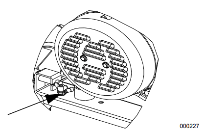
Use battery charger plug to keep the battery charged and ready for use. Battery charging should be done in a dry location.
1. Plug charger into Battery Charger Input jack, located on the control panel. See Fig ure 3-5. Plug wall receptacle end of battery charger into 120 Volt AC wall outlet.
2. Unplug battery charger from wall outlet and control panel jack when generator is to be in use.
Figure 3-5. Battery Charger Input Jack
WARNING
Environmental Hazard. Always recycle batteries at an official recycling center in accordance with all local laws and regulations. Failure to do so could result in environmental damage, death or serious injury.
Maintenance and Troubleshooting
Maintenance
Regular maintenance will improve perfor mance and extend engine/equipment life. Generac Power Systems, Inc. recommends that all maintenance work be performed by an Independent Authorized Service Dealer (IASD). Regular maintenance, replacement, or repair of the emissions control devices and systems may be performed by any repair shop or person of the owner’s choosing. To obtain emissions control warranty service free of charge, the work must be performed by an IASD. See the emissions warranty.
NOTE: Call 1-888-GENERAC (1-888-436- 3722) with questions about component replacement.
Maintenance Schedule
Follow maintenance schedule intervals, whichever occurs first according to use.
NOTE: Adverse conditions will require more frequent service.
NOTE: All required service and adjustments should be each season as detailed in the fol lowing chart.
At Each Use
Check engine oil level
Every 100 Hours or Every Season*
Change oil ǂ
Inspect/clean spark arrestor
Every Season
Replace Spark Plug
Check Valve Clearance***
Every 200 Hours or Every Season
Inspect/clean air cleaner filter**
ǂ Change oil after first 30 hours of operation, then every season.
* Change oil every month when operating under heavy load or in high temperatures.
** Clean more often under dirty or dusty operating conditions. Replace air filter parts if they cannot be adequately cleaned.
*** Check valve clearance and adjust if neces sary after first 50 hours of operation and every 300 hours thereafter.
Preventive Maintenance
Dirt or debris can cause improper operation and equipment damage. Clean generator daily or before each use. Keep area around and behind muffler free from combustible debris. Inspect all cooling air openings on generator.
WARNING
Personal injury. Do not insert any object through the air cooling slots. Generator can start at any time and could result in death, serious injury, and unit damage.
Use a damp cloth to wipe exterior surfaces clean.
Use a soft bristle brush to loosen caked on dirt, oil, etc.
Use a vacuum to pick up loose dirt and debris.
Low pressure air (not to exceed 25 psi) may be used to blow away dirt. Inspect cooling air slots and openings on generator. These openings must be kept clean and unobstructed.
NOTE: DO NOT use a garden hose to clean generator. Water can enter engine fuel system and cause problems. If water enters generator through cooling air slots, some water will be retained in voids and crevices of rotor and sta tor winding insulation. Water and dirt buildup on generator internal windings will decrease insulation resistance of windings.
Engine Maintenance
WARNING
Accidental start-up. Disconnect spark plug wires when working on unit. Failure to do so could result in death or serious injury.
Engine Oil Recommendations
To maintain the product warranty, the engine oil should be serviced in accordance with the recommendations of this manual. For your convenience, maintenance kits designed and intended for use on this product are available from the manufacturer that include engine oil, oil filter, air filter, spark plug(s), a shop towel and funnel. These kits can be obtained from an Independent Authorized Service Dealer (IASD).
Inspect Engine Oil Level
WARNING
Risk of burns. Allow engine to cool before draining oil or coolant. Failure to do so could result in death or serious injury.
Inspect engine oil level prior to each use, or every 8 hours of operation.
1. Place generator on a level surface.
2. Clean area around oil fill.
3. See Figure 4-1. Remove oil fill cap and wipe dipstick clean.
Figure 4-1. Engine Oil Fill
4. Screw dipstick into filler neck. Remove dipstick and verify oil level is within safe operating range. See Figure 4-2.
Figure 4-2. Safe Operating Range
5. Add recommended engine oil as neces sary.
6. Replace oil fill cap and hand-tighten.
NOTE: Some units have more than one oil fill location. It is only necessary to use one oil fill point.
Change Engine Oil
WARNING
Accidental start-up. Disconnect spark plug wires when working on unit. Failure to do so could result in death or serious injury.
When using generator under extreme, dirty, dusty conditions, or in extremely hot weather, change oil more frequently.
NOTE: Don’t pollute. Conserve resources. Return used oil to collection centers.
Change oil while engine is still warm from run ning, as follows:
1. Place generator on a level surface.
2. Disconnect the spark plug wire from the spark plug and place the wire where it cannot contact spark plug.
3. Clean area around oil fill, and oil drain plug.
4. Remove oil fill cap.
5. Remove oil drain plug and drain oil com pletely into a suitable container.
6. Install oil drain plug and tighten securely.
7. Slowly pour oil into oil fill opening until oil level is between L and H marks on dip stick. DO NOT overfill.
8. Install oil fill cap, and finger tighten.
9. Wipe up any spilled oil.
10. Properly dispose of oil in accordance with all applicable regulations.
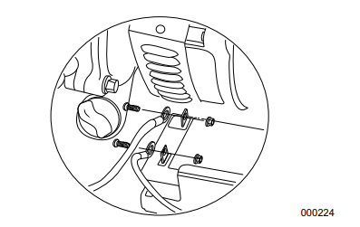
Air Filter
Engine will not run properly and may be dam aged if run with a dirty air filter. Service air fil ter more frequently in dirty or dusty conditions. To service air filter:
1. See Figure 4-3. Turn knob (A) and remove air filter cover.
2. Wash in soapy water. Squeeze filter dry in clean cloth (DO NOT TWIST).
3. Clean air filter cover before re-installing it.
Figure 4-3. Air Filter Assembly
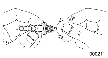
Service Spark Plug
To service spark plug:
1. Clean area around spark plug.
2. Remove and inspect spark plug.
3. Inspect electrode gap with wire feeler gauge and reset spark plug gap to 0.028 - 0.031 in (0.70 - 0.80 mm). See Figure 4-4.
Figure 4-4. Spark Plug
NOTE: Replace spark plug if electrodes are pitted, burned or porcelain is cracked. Use ONLY recommended replacement plug. See Specifications.
4. Install spark plug finger tight, and tighten an additional 3/8 to 1/2 turn using spark plug wrench.
Battery Replacement (if applicable)
NOTE: The battery shipped with the generator has been fully charged. A battery may lose some charge when not in use for prolonged periods of time. If battery is unable to crank engine, plug in the 12V charger included in the accessory box. See Charging the Battery.
IMPORTANT NOTE: Running the generator does not charge battery.
WARNING
Accidental Start-up. Disconnect the negative battery cable, then the positive battery cable when working on unit. Failure to do so could result in death or serious injury.
See Figure 4-5.
1. Disconnect negative (-) battery terminal FIRST (black wire).
2. Disconnect positive (+) battery terminal SECOND (red wire).
Figure 4-5. Battery Connection
3. Install new battery. Install hold down bracket and tighten.
4. Connect positive (+) battery terminal (red wire) FIRST (red wire). Slide rubber boot over connection hardware.
Environmental Hazard. Always recycle batteries at an official recycling center in accordance with all local laws and regulations. Failure to do so could result in environmental damage, death or serious injury.
Inspect Muffler and Spark Arrester
NOTE: It is a violation of California Public Resource Code, Section 4442, to use or oper ate the engine on any forest-covered, brush covered, or grass-covered land unless the exhaust system is equipped with a spark arrester, as defined in Section 4442, main tained in effective working order. Other states or federal jurisdictions may have similar laws.
Contact original equipment manufacturer, retailer, or dealer to obtain a spark arrester designed for exhaust system installed on this engine.
NOTE: Use ONLY original equipment replace ment parts.
Inspect muffler for cracks, corrosion, or other damage. Remove spark arrester, if equipped, inspect for damage or carbon blockage. Replace parts as required.
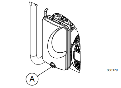
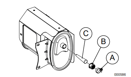
Inspect Spark Arrester Screen
WARNING
Hot Surfaces. When operating machine, do not touch hot surfaces. Keep machine away from combustibles during use. Hot surfaces could result in severe burns or fire.
1. Loosen clamp (A) and remove screw. See Figure 4-6.
2. Inspect screen (B) and replace if torn, per forated or otherwise damaged. If screen is not damaged, clean with commercial sol vent.
3. Replace spark arrestor cone (C) and screen (B). Secure with clamp and screw.
Figure 4-6. Spark Arrestor Screen
Valve Clearance
Important: Please contact an Independent Authorized Service Dealer for service assis tance. Proper valve clearance is essential for prolonging the life of the engine.
Check valve clearance after the first fifty-hours of operation. Adjust as necessary.
Explosion and Fire. Fuel and vapors are extremely flammable and explosive. Store fuel in a well ventilated area. Keep fire and spark away. Failure to do so will result in death or serious injury.
WARNING
Risk of Fire. Verify machine has properly cooled before installing cover and storing machine. Hot surfaces could result in fire.
It is recommended to start and run the genera tor for 30 minutes, every 30 days. If this is not possible, refer to the following list to prepare unit for storage.
DO NOT place a storage cover on a hot generator. Allow unit to cool to room tem perature before storage.
DO NOT store fuel from one season to another unless properly treated.
Replace fuel container if rust is present. Rust in fuel will cause fuel system prob lems.
Cover unit with a suitable protective, mois ture resistant cover.
Store unit in a clean and dry area.
Always store generator and fuel away from heat and ignition sources.
Prepare Fuel System for Storage
Fuel stored over 30 days can go bad and damage fuel system components. Keep fuel fresh, use fuel stabilizer.
If fuel stabilizer is added to fuel system, pre pare and run engine for long term storage. Run engine for 10-15 minutes to circulate sta bilizer throughout fuel system. Adequately prepared fuel can be stored up to 24 months.
NOTE: If fuel has not been treated with fuel stabilizer, it must be drained into an approved container. Run engine until it stops from lack of fuel. Use of fuel stabilizer in fuel storage container is recommended to keep fuel fresh.
1. Change engine oil.
2. Remove spark plug.
3. Pour tablespoon (5-10cc) of clean engine oil or spray a suitable fogging agent into cylinder.
WARNING
Vision Loss. Eye protection is required to avoid spray from spark plug hole when cranking engine. Failure to do so could result in vision loss.
4. Pull starter recoil several times to distrib ute oil in cylinder.
5. Install spark plug.
6. Pull recoil slowly until resistance is felt. This will close valves so moisture cannot enter engine cylinder. Gently release recoil.
Change Oil
Change engine oil before storage. See Change Engine Oil.
Troubleshooting
PROBLEM
CAUSE
CORRECTION
Engine is running, but AC output is not available.
1. Circuit breaker OPEN.
2. Poor connection or defective cord set.
3. Connected device is bad.
4. Fault in generator.
5. GFCI receptacle is OPEN (if equipped).
1. Reset circuit breaker.
2. Check and repair.
3. Connect another device that is in good condition.
4. Contact IASD.
5. Correct ground fault and press reset button on GFCI receptacle (if equipped).
Engine runs well at no-load, but bogs when load is applied.
1. Short circuit in a connected load.
2. Generator is overloaded.
3. Engine speed is too slow.
4. Shorted generator circuit.
5. Clogged spark arrestor.
1. Disconnect shorted electrical load.
2. See Know Generator Limits.
3. Contact IASD.
4. Contact IASD.
5. Clean spark arrestor screen.
Engine will not start; or starts and runs rough.
1. Fuel shut-off is OFF.
2. Dirty air filter.
3. Out of fuel.
4. Stale fuel.
5. Spark plug wire not connected to spark plug.
6. Bad spark plug.
7. Water in fuel.
8. Overchoking.
9. Low oil level.
10. Excessive rich fuel mixture.
11. Intake valve stuck open or closed.
12. Engine lost compression.
1. Turn fuel shut-off ON.
2. Clean or replace air filter.
3. Fill fuel tank.
4. Drain fuel tank and fill with fresh fuel.
5. Connect wire to spark plug.
6. Replace spark plug.
7. Drain fuel tank; fill with fresh fuel.
8. Set choke to no choke posi tion.
9. Fill crankcase to correct level.
10. Contact IASD.
11. Contact IASD.
12. Contact IASD.
Engine shuts down during operation.
1. Out of fuel.
2. Low oil level.
3. Fault in engine.
1. Fill fuel tank.
2. Fill crankcase to correct level.
3. Contact IASD.
Engine lacks power.
1. Load is too high.
2. Dirty air filter.
3. Engine needs to be serviced.
1. Reduce load (see Know Gen erator Limits).
2. Clean or replace air filter.
3. Contact IASD.
Engine surges or stumbles.
1. Choke is opened too soon.
2. Carburetor is running too rich or too lean.
1. Set choke to halfway position until engine runs smoothly.