
Every Wheeler® product is warranted to be free from defects in materials and workmanship for a period of one (1) year from the date of original purchase. Any such defects for
which Battenfeld Technologies, Inc. (BTI) receives written notice by the original retail purchaser will be remedied within a reasonable time after such notication and delivery of
the covered products as provided herein. BTI will, at its option, repair or replace without charge, except for transportation costs, covered products that are defective in either
materials or workmanship that have been used and maintained in accordance with the provided instructions. Warranty claims (in writing) and the product or part thereof
concerned should be delivered, postage prepaid, to BTI at the address above. In addition, a copy of the bill of sale indicating date of purchase must be included. Please include
your physical address, phone number and email address. BTI will not be responsible for defects or malfunctions resulting from careless handling, unauthorized adjustments or
modications, corrosion, neglect, abuse, ordinary wear and tear, or unreasonable use, commercial use, criminal misuse, negligence, or use under the inuence of drugs or alcohol.
This warranty does not apply to normal wear or to items whose life is dependent on their use and care. UNDER NO CIRCUMSTANCES SHALL BTI BE RESPONSIBLE FOR INCIDENTAL
OR CONSEQUENTIAL DAMAGES WITH RESPECT TO ECONOMIC LOSS, INJURY, DEATH OR PROPERTY DAMAGE, WHETHER AS A RESULT OF BREACH OF THIS WARRANTY,
NEGLIGENCE OR OTHERWISE. Some states do not allow the exclusion or limitation of implied warranties and/or incidental or consequential damages, so the above limitations or
exclusions may not apply to you. This warranty gives you specic legal rights, and you may also have other rights which vary from state to state.
Scope Mounting Kit 1” Product# 540127
Scope Mounting Kit Combo 1” and 30mm Product# 545454
Instruction# 1009310
Revision: G
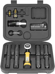
Instructions and Usage
A. Lapping Bar Handle
B. Flex Driver
C. 1” Lapping Bar
D. Alignment Bars
E. Level-Level-Level (Scope Turret and Receiver Level)
F. F.A.T. Wrench
G. 220 Grit Lapping Compound
H. Low-strength thread locking compound
I.
Square Drive Adapter Bit
T15 Torx Bit
T20 Torx Bit
3/32” Allen Bit
7/64” Allen Bit
5/32” Allen Bit
#10 Deluxe Flat Blade Bit
#11 Deluxe Flat Blade Bit
#32 Deluxe Flat Blade Bit
Leupold / Buehler Windage Bit
1/2” x 1/4” Socket Driver
Combo kit includes 1” and 30mm - 30mm NOT SHOWN ABOVE - lapping and alignment bars.
Step by step instructional video located Online at
www.btibrands.com/wheeler-smk-video/
A
B
C
D
E
I
G
H
F
PROFESSIONAL SCOPE MOUNTING KITS
USER INSTRUCTIONS
F
IREARM
A
CCURIZING
T
ORQUE
WRENCH
D
e
c
r
e
a
s
e
T
or
q
u
e
Increase Torque
= =
Instruction #1009310
PHOTO 1 PHOTO 2 PHOTO 3
The Wheeler
®
Engineering F.A.T. Wrench
®
is a hand driven, click/clutch style torque wrench that is very useful for applying the
necessary torque to most rearm and rearm accessory fasteners. The F.A.T. Wrench
®
features a thick ergonomic handle, a
standard ¼” hex drive tip, and can be used to apply torque from 10 to 65 in-lbs at 5 in-lb increments. Common uses include, but
are not limited to; installation of scope ring and base screws, action screws and trigger guard screws. With proper care and use, the
F.A.T. Wrench
®
will provide you with a lifetime of reliable service. Package includes 9 bits and a square drive adapter.
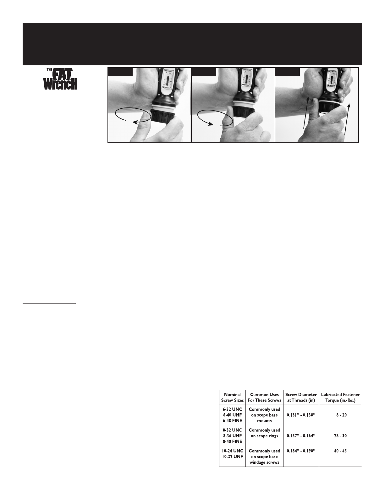
TO ADJUST THE F.A.T. WRENCH
®
, PLEASE FOLLOW THESE STEPS TO GUARANTEE THE MOST ACCURATE TORQUE SETTINGS:
1. Begin with the F.A.T. Wrench
®
adjusted to the lowest torque setting. To do this, grasp the body of the F.A.T. Wrench
®
as shown in PHOTO 1. Using your other hand,
grasp the black knob at the bottom end of the handle. Pull the knob away from the handle to unlock it, and turn it counter-clockwise. The knob is spring loaded and
will return to the locked position when it is released, preventing it from being turned. You must repeatedly pull the knob and turn it counter-clockwise until it comes
to a stop. The red mark on the sliding indicator should be visible at the bottom of the scale below the 10 tic mark, as shown in PHOTO 1. This is also the where the
F.A.T. Wrench should be adjusted when it is not in use.
2. Using the same technique described in Step 1 to adjust the wrench, pull and turn the knob clockwise until the red mark on the sliding indicator is aligned with the
desired tic mark on the scale. This can be seen in PHOTO 2, where the F.A.T. Wrench
®
is adjusted to 30 in-lbs.
3. When the F.A.T. Wrench
®
is adjusted to the desired torque setting, make sure the knob has returned to the locked position. This may require turning the knob slightly
one way or the other and pressing it back into the locked position. See PHOTO 3.
4. Insert the bit needed into the hex drive tip. The F.A.T. Wrench
®
can now be used to apply torque to the fastener.
5. Tighten the fastener by turning the F.A.T. Wrench
®
clockwise. As the fastener begins to get tight, turn the F.A.T. Wrench
®
SLOWLY until you hear an audible click. Turn
it two more for a total of 3 clicks. The fastener has now been tightened with the torque specied on scale.
6. After use, return the F.A.T. Wrench
®
to the lowest torque setting as described in Step 1.
Note: When using the F.A.T. Wrench
®
to torque small fasteners, make sure the bit and the head of the fastener are correctly aligned. Correct alignment
will prevent damage to both the bit and fastener.
A FEW USEFUL TIPS:
• The F.A.T. Wrench
®
is used like a screwdriver; it is not a ratcheting device.
• Never leave the F.A.T. Wrench
®
adjusted at high torque settings for extended periods of time. Doing so will damage the internal mechanism, resulting in inaccurate
torque adjustment. ALWAYS ADJUST THE F.A.T. WRENCH
®
TO THE LOWEST TORQUE SETTING AFTER USE.
• Never adjust the F.A.T. Wrench
®
beyond a torque setting of 65 in-lbs. Doing so will damage the internal mechanism, resulting in inaccurate torque adjustment.
• The F.A.T. Wrench
®
is compatible with all of the bits contained in the Wheeler Engineering 89 Piece Screwdriver Set.
• The F.A.T. Wrench
®
was designed for +/- 2 in-lbs accuracy up to 40 in-lbs, +/- 5% over 40 in-lbs.
• The F.A.T. Wrench
®
can be used to apply torque to any fasteners; it is not limited to rearms and rearm accessories.
• Small, inexpensive screws can be damaged with high torque settings. Be sure to comply with recommended settings.
• Small bits can also be easily damaged with high torque settings. Replacement bits are available from many of our dealers and through our website.
RECOMMENDED TORQUE SETTINGS:
ALWAYS follow torque specications provided by scope base or ring manufacturer.
F.A.T. Wrench
®
Torque Range is 5 to 65 inch-pounds
Before applying torque to any fastener, consider whether the fastener is lubricated or dry/
degreased. Lubricated fasteners require much less torque to achieve consistent clamping power
compared to dry un-lubricated fasteners. Keep in mind that most fasteners used for installing
gun accessories are coated with oil to prevent corrosion. This oil as well as removable thread-
locking compounds that are often applied to screw threads should be considered as lubricant.
NOTE: The values tabulated below are for high grade (SAE Grade 8 or equivalent)
steel fasteners. If you are unsure about the size or quality of the fastener you
are installing, start with a lower torque value and only increase to the maximum
torques listed if you feel comfortable doing so. Bits are considered “use” items and
are not warrantied against bending or breakage.
The Wheeler Professional Scope Mounting Kits include everything you will need to properly mount a scope. An
instructional video outlining step by step instructions can found Online at www.btibrands.com/wheeler-smk-video/
These printed instructions can be referenced for additional detail on each of the key components of the kit.
The alignment of a rie scope’s crosshairs relative to the axis of the bore is
very important, especially at long range.
The Level-Level-Level works by aligning a scope’s horizontal plane with
a horizontal plane on the rie’s receiver. Manufacturing processes of scopes
and ries offer accessible horizontal platforms for alignment.
There are two respects of scope alignment:
1. Alignment of the scope to the rie.
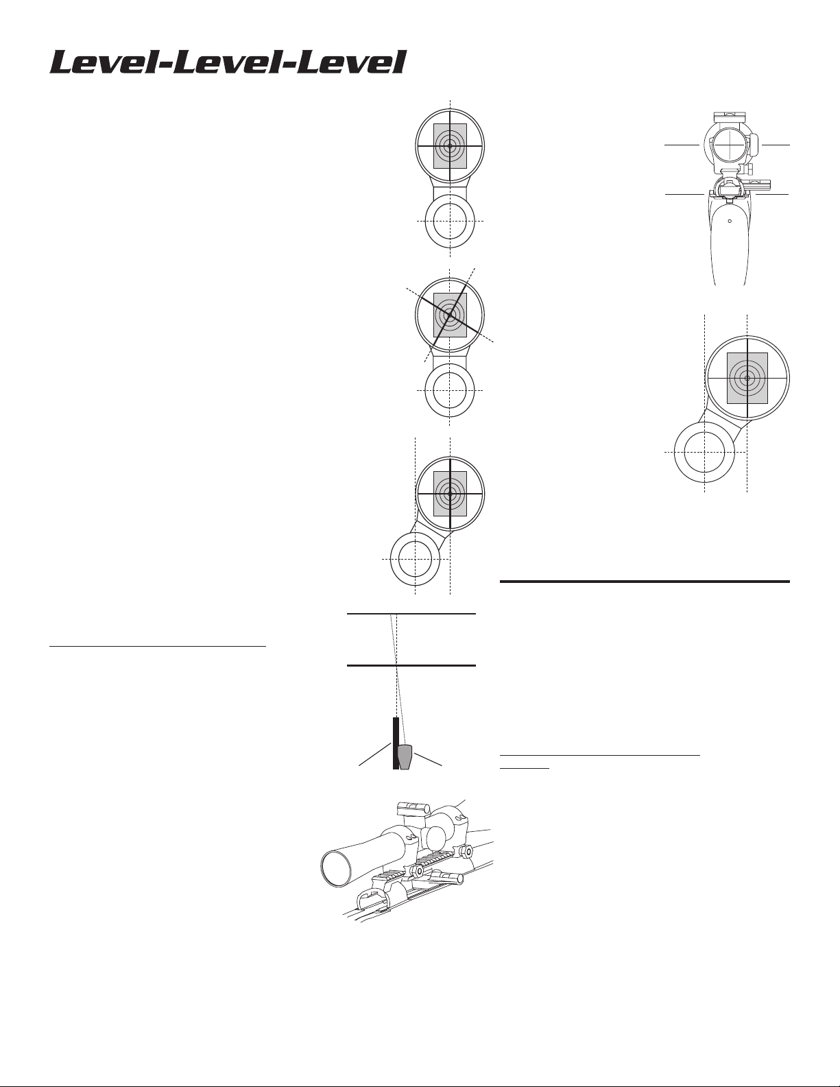
2. Alignment of the crosshairs as controlled by the shooter. An aligned
scope reticle has its vertical portion positioned so that if it were extended
downward, it would pass through the center of the bore. See Photo 1.
If a scope is misaligned and you attempt to adjust the windage or elevation,
the reticle will not track vertically or horizontally with respect to the bore.
See Photos 2. In this instance, adjusting elevation upwards will also move
the point of impact to the right. This is frustrating and wasteful during sight-in.
If a scope is misaligned clockwise and you hold the rie such that the
horizontal reticle is level, the rie can only be perfectly sighted in at one
distance. See Photos 3 and 4. In this instance where the rie is sighted
in for 100 yards, the bullet will impact left of the point of aim for any
distance beyond 100 yards and right of the point of aim for any distance
less than 100 yards.
If a shooter is given a zeroed rie with an aligned scope, but cants the
rie to the right, a shot at a range beyond the sight-in distance will
strike to the right and likely low, depending on the cartridge trajectory
and range.
NOTE: It is imperative that every attempt possible is made
to ensure the scope crosshairs are properly maintained in
horizontal and vertical alignment while shooting. Proper
alignment will ensure the scope reticle tracks vertically
and horizontally correctly while making adjustments for
elevation and windage.
HOW TO USE THE LEVEL-LEVEL-LEVEL
For most bolt-action ries: See Photos 5 and 6.
1. Secure rie in a padded vise, such as the Tipton Gun Vise.
Place magnetic base of Action Level across receiver rails
and maneuver rie until bubble is centered.
2. Loosen scope rings and remove turret cover.
3. Place scope level across the elevation adjustment screw
and rotate the scope until bubble is centered.
4. Tighten scope rings.
5. Crosshairs are now perfectly level for ultimate accuracy
at
any distance.
Bolt-action ries with small receivers, or three-lug
systems like the Cooper: Locate another horizontal
area to attach the receiver level. The Cooper offers an
area immediately behind the rear receiver bridge. (You
can use the scope bases although they are not necessarily
as accurate as the raceway rails.) AR15 style ries - On
attops the scope base is machined as part of the receiver;
so use it as a platform. The magnetic base of the level does
not adhere to the aluminum, but it can be held in place with
nger pressure or a rubber band. Carry handle versions
offer no surfaces on the upper receiver. The bottom surface
that meets with the lower receiver is machined. Position
the level crossways on the underside of the receiver using
imaginative attachment procedures, such as rubber bands
or nger pressure.
USER INSTRUCTIONS
3.
1.
2.
100 Yards
Barrel Scope
200 Yards
4.
7.
5.
6.
Lever-action ries with offset
scopes, M1, and M1A:
M1 and M1A’s have ats behind the
rear sight. The level can be attached
across the top edges of the receiver
on the Winchester M94. Other
applications may require imaginative
treatment. See Photo 7.
Autoloading and pump ries
and slug-shooting shotguns
with at sides: These rearms
seldom have a horizontal plane
available for attachment of the
level, unless you remove the trigger
assembly and bridge the underside
of the receiver. An unusual, but
practical approach is to secure the
rearm on its left side, attach the
receiver level to the right side of the
receiver, level it, and place the scope
on level of the windage (side) turret.
Troubleshooting: If you have
been shooting for any length of time
with unlevel crosshairs before using
the Level-Level-Level, you may nd
it disconcerting when you shoulder
your rearm and the crosshairs
appear skewed. This is normal. You may have been consciously or
unconsciously canting your rie to align the crosshairs horizontally.
The Level-Level-Level works and if used correctly, can be trusted
to align your crosshairs perfectly. You may have to unlearn your
bad habits to get used to shooting a scope with level crosshairs.
Scope Ring Alignment & Lapping Kit
USER INSTRUCTIONS
Dimensional variances in scope bases, rings, and rearm receivers
combine to cause scope rings to be misaligned. There are two
reasons for aligning your scope rings:
1. Misaligned rings cause stress on the scope tube, which can dent
the tube, distort the reticle, and cause adjustment problems.
2. Properly aligned rings create more surface contact with the
scope tube to keep scopes in place during heavy recoil.
USING THE SCOPE ALIGNMENT KIT
Warning: Be sure rearm is unloaded before performing
any gunsmithing or maintenance.
1. Clamp rearm in a vise with padded jaws. We recommend the
use of the Tipton
®
Gun Vise™ to hold the rearm
securely and safely.
2. Follow manufacturer’s instructions for mounting bases and rings.
NOTE: Scope manufacturers specically say not to use
the scope tube for mounting dovetail rings because of
the risk of bending the tube and voiding the warranty.
The Lapping Shaft may be used to install dovetail rings.
3. Check initial alignment after the base and rings
have been mounted.
a. Remove top half of both rings. Keep ring pairs together and
do not reverse top halves on their bottom halves. Most rings
are manufactured as a single piece before they are split.
Note: It is a good idea to mark the rings so you don’t mix
or reverse them.
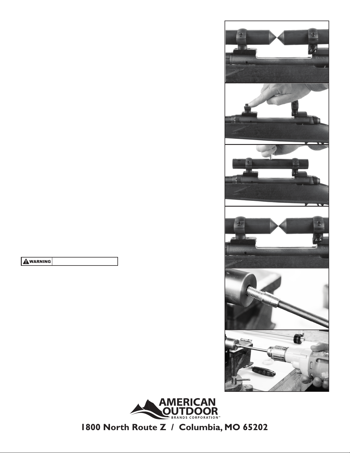
b. Lay an Alignment Bar in each of the ring bottoms, pointed ends facing, just
short of making contact. Adjust them so the pointed ends are approximately
midway between the rings. See Photo 1.
c. Replace ring top halves. Tighten ring screws as if scope were being secured.
d. If the scope rings are aligned, the points of the Alignment Bars will be aligned
both horizontally and vertically.
e. If the points are not in alignment:
1. Check that ring top halves are not switched / reversed.
2. Slightly rotate dovetail mount rings (if equipped) to
improve windage alignment.
3. Adjust rear ring windage screws (if equipped).
4. Two-piece bases may need to be shimmed to improve
elevation alignment.
5. Align the rings as closely as possible before lapping; lapping will remove
minor alignment issues.
4. Lapping the scope rings.
a. Loosen the rings enough to remove alignment bars.
b. Apply lapping compound to the inside of both halves of the rings.
See Photo 2.
c. Slide the lapping bar through both sets of rings.
d. Tighten rings just enough to apply pressure to the rings but still allow the
lapping bar to slide.
e. Thread handle into hole on lapping bar. See Photo 3.
(Skip to 5 if using Flex Driver)
NOTE: Two threaded holes are provided in the lapping bar for
the handle. For most applications, mounting the handle in the
center of the lapping bar will provide the most control and ease
of use while lapping. For mounting systems with closely spaced
rings, it may be more convenient to mount the handle at the end
of the bar.
f. Begin lapping the scope rings by rotating the lapping bar side to side and
sliding it back and forth. Rings may need to be gradually tightened as you
remove material.
g. Periodically check your progress. Remove the lapping bar, clean any lapping
compound from the rings, and reinstall the alignment bars. Make sure you
don’t remove so much material that the rings will no longer tighten
onto the scope.
h. Repeat until alignment bars match. See Photo 4.
i. Clean scope rings to remove all grit. Do not remove bases or rings or you
will have to realign and/or re-lap.
j. Mount scope according to manufacturer’s instructions.
5. Flex Drive Instructions
a. Loosen the rings enough to remove alignment bars.
b. Apply lapping compound to the inside of both halves of the rings.
See Photo 2.
c. Slide the lapping bar through both sets of rings.
d. Tighten rings just enough to apply pressure to the rings but still allow the
lapping bar to slide.
e . Thread Flex Driver into the Lapping Bar. (Thread locking compound can be
used for a permanent assembly) See Photo 5
f. Chuck the other end of the Flex Driver in a drill See Photo 6
g. Using a drill, apply steady pressure into the rings, slowly turn the lapping bar
and slide back and forth. Ring may need to be gradually tightened as you
remove material.
h. Periodically check your progress. Remove the lapping bar, clean any lapping
compound from the rings, and reinstall the alignment bars. Make sure you
don’t remove so much material that the rings will no longer tighten
onto the scope.
i. Repeat until alignment bars match. See Photo 4.
j. Clean scope rings to remove all grit. Do not remove bases or rings or you
will have to realign and/or re-lap.
k. Mount scope according to manufacturer’s instructions.
1.
2.
3.
4.
5.
6.
Always wear safety glasses.
