BEFORE YOU BEGIN
Read these instructions completely and carefully.
IMPORTANT – Save these instructions for local
electrical inspector’s use.
IMPORTANT – Observe all governing codes and
ordinances.
Install the clothes dryer according to the manufacturer’s
instructions and local codes.
Note to Installer – Be sure to leave these instructions
with the Consumer.
Note to Consumer – Keep these instructions for future
reference.
Clothes dryer installation must be performed by a
qualified installer.
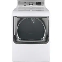
This dryer must be exhausted to the outdoors.
Before the old dryer is removed from service or
discarded, remove the dryer door.
Service information and the wiring diagram are located
in the control console.
Do not allow children on or in the appliance. Close
supervision of children is necessary when the appliance
is used near children.
Proper installation is the responsibility of the installer.
Product failure due to improper installation is not
covered under the Warranty
.
Install the dryer where the temperature is above 50°F
for satisfactory operation of the dryer control system.
5HPRYHDQGGLVFDUGH[LVWLQJSODVWLFRUPHWDOIRLOGXFW
and replace with UL-listed duct.
Questions? Call 800.GE.CARES (800.432.2737) or visit our Web site at: GEAppliances.com
- Fire Hazard
WARNING
Clothes dryer installation must be performed by a
qualified installer.
Install the clothes dryer according to these
instructions and local codes.
DO NOT install a clothes dryer with flexible plastic
venting materials. If flexible metal (semi-rigid or
foil-type) duct is installed, it must be UL-listed and
installed in accordance with the instructions found
in “Connecting the Dryer to House Vent” later in
this manual. Flexible vent materials are known to
collapse, be easily crushed and trap lint. These
conditions will obstruct dryer airflow and increase
the risk of fire.
DO NOT install or store this appliance in any
location where it could be exposed to water or
weather.
To reduce the risk of severe injury or death, follow
all installation instructions.
Save these instructions. (Installers: Be sure to leave
these instructions with the customer.)
Installation Dryers
Instructions
01
This is the safety alert symbol. This symbol alerts you to potential hazards that can kill you or hurt you and others.
$OOVDIHW\PHVVDJHVZLOOIROORZWKHVDIHW\DOHUWV\PERODQGWKHZRUG´'$1*(5µ´:$51,1*µRU´&$87,21µ7KHVH
words are defined as:
Indicates a hazardous situation which, if not avoided, will result in death or serious injury.
Indicates a hazardous situation which, if not avoided, could result in death or serious injury.
Indicates a hazardous situation which, if not avoided, could result in minor or moderate injury.
DANGER
WARNING
CAUTION
31-16767 04-15 GE
Printed in Mexico
234D2318P001
Installation Instructions
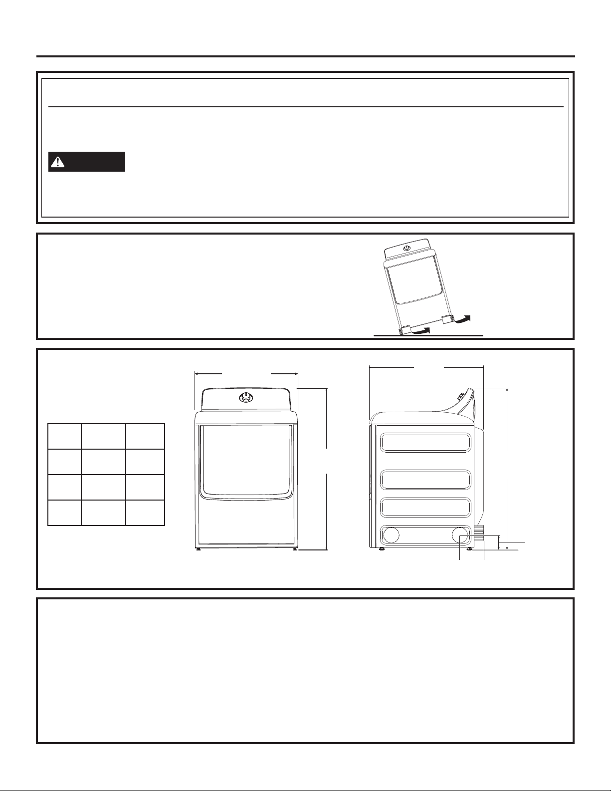
Tilt the dryer sideways and remove the foam
shipping pads by pulling at the sides and breaking
them away from the dryer legs. Be sure to remove all
of the foam pieces around the legs.
5HPRYHOLWHUDWXUHDQGEDJFRQWDLQLQJDFFHVVRULHV
UNPACKING YOUR DRYER
STEAM WATER HOSES:
GE strongly recommends the use of factory specified parts.
These hoses are manufactured and tested to meet GE
specifications.
GE strongly recommends the use of new water supply hoses.
Hoses degrade over time and need to be replaced every 5
years to reduce the risk of hose failures and water damage.
Parts and Accessories
Order on-line at GEApplianceParts.com, 24 hours a day or
by phone at 800.626.2002 during normal business hours.
Part Number Accessory
WE25X20060 Complete Kit (hoses, Y-adapter
washers) (included)
OR
WE1M847 Long Hose and
WE01X22395 Short Hose
PM14X10056 Dryer door opening vent brush
(not included)
WX14X10007 LintEater™ Dryer rotary tube brush
(not included)
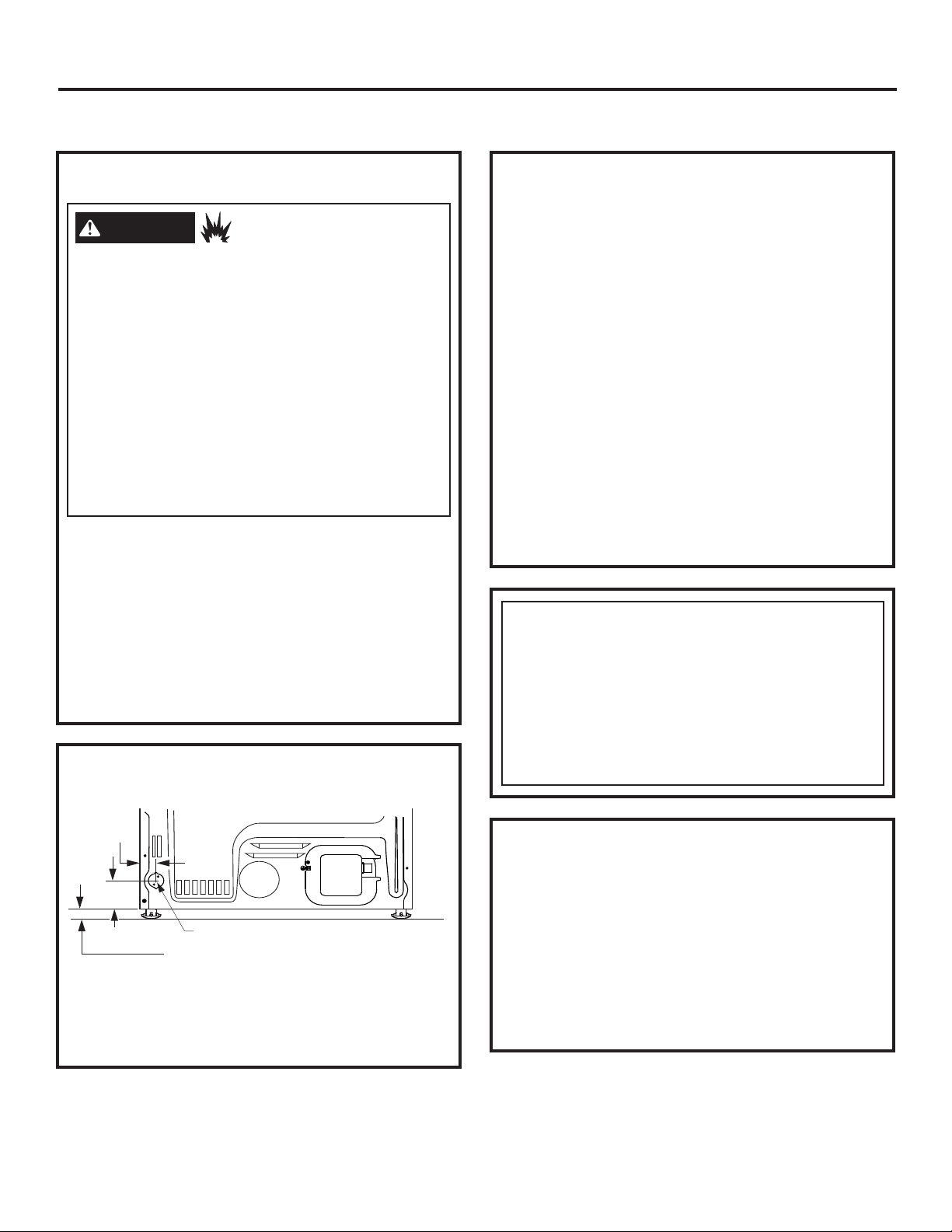
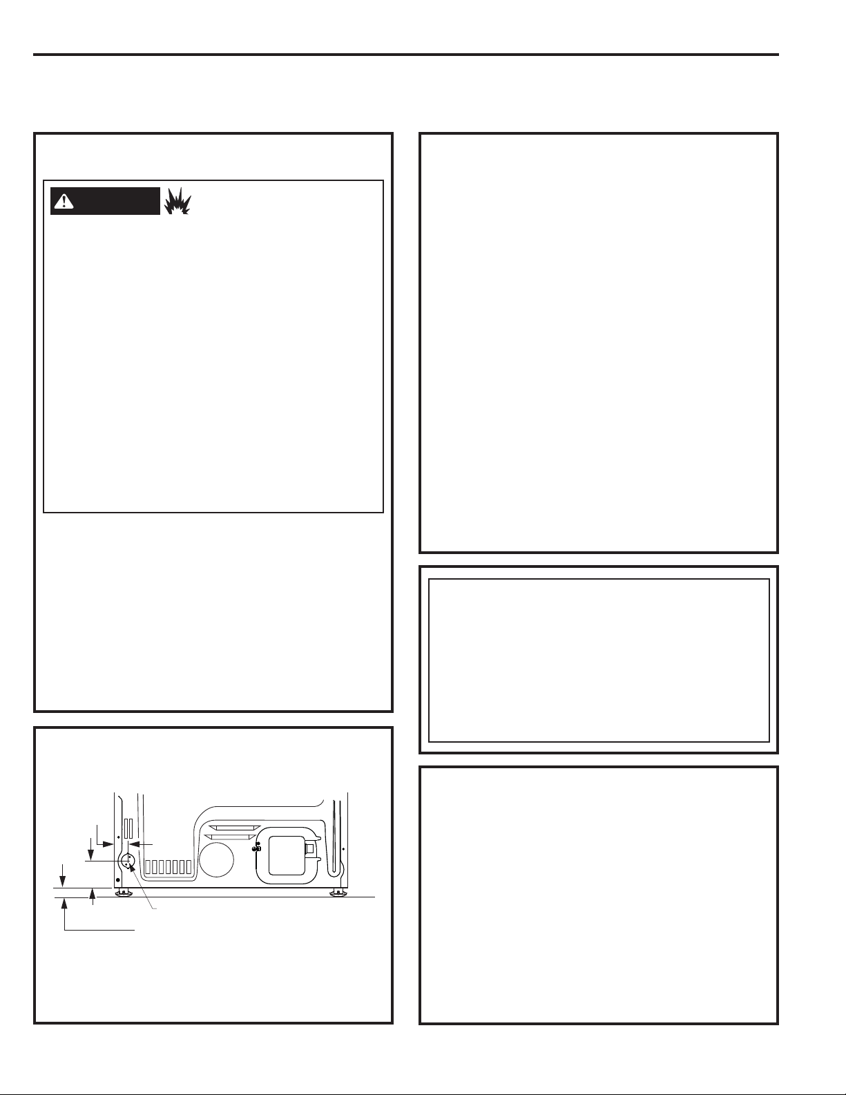
2
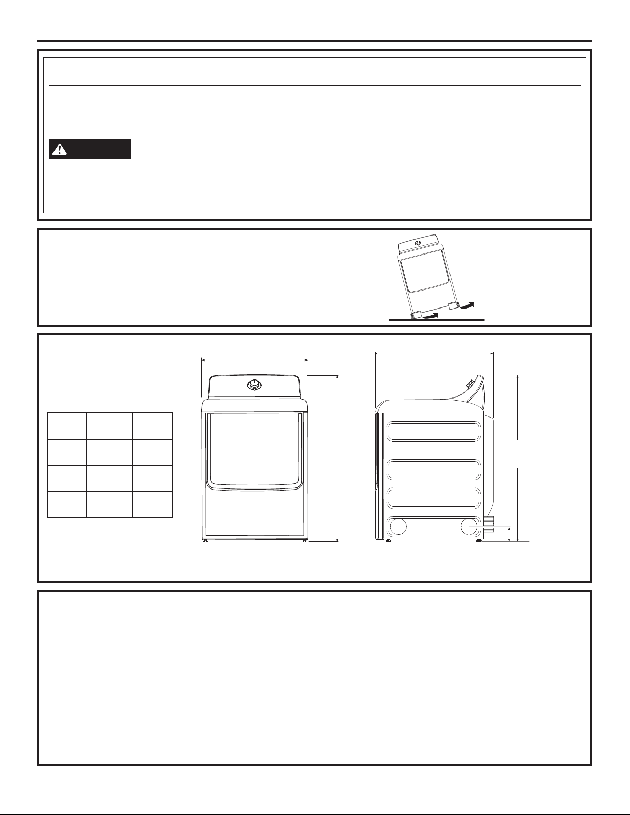
ROUGH-IN
DIMENSIONS
State of California Proposition 65 Warnings:
The California Safe Drinking Water and Toxic Enforcement Act requires the governor of California to publish a list of substances
known to the state to cause cancer, birth defects or other reproductive harm and requires businesses to warn of potential exposure
to such substances.
WARNING
This product contains one or more chemicals known to the State of California to cause cancer, birth defects or
other reproductive harm.
Gas appliances can cause low-level exposure to some of these substances, including benzene, carbon monoxide, formaldehyde and
soot, caused primarily by the incomplete combustion of natural gas or LP fuels. Exposure to these substances can be minimized by
properly venting the dryer to the outdoors.
4 5/8”
(11.7 cm)
Y
X
27”
(68.8 cm)
X
4 1/4”
(10.8 cm)
Side ViewFront View
Cubic
Foot
XY
6.0
43 3/8”
(110 cm)
26 3/4”
(68 cm)
7.0
43 3/8”
(110 cm)
29 1/2”
(75 cm)
7.3
43 3/4”
(111 cm)
30 1/2”
(78 cm)
Installation Instructions
REQUIREMENTS FOR ALCOVE OR
CLOSET INSTALLATION
MOBILE OR MANUFACTURED HOME
INSTALLATION
3
- Explosion Hazard
WARNING
Keep flammable materials and vapors, such as gasoline,
away from dryer.
Place dryer at least 18” (46 cm) above the floor for a
garage installation.
Failure to do so can result in death, explosion, or fire.
If the dryer is approved for installation in an alcove or
closet, it will be stated on a label on the dryer back.
The dryer MUST be vented to the outdoors. See
WKH(;+$867,1*7+('5<(5VHFWLRQ
Minimum clearance between dryer cabinet and
adjacent walls or other surfaces is:
0” either side
3” front
0” rear but a 1” minimum is recommended
Minimum vertical space from dryer to overhead
shelves, cabinets, ceilings, etc., is 1” on top.
Consideration must be given to provide adequate
clearance for installation and service.
Closet doors must be louvered or otherwise
ventilated and have at least 60 square inches of
open area. If the closet contains both a washer
and a dryer, doors must contain a minimum of
120 square inches of open area.
NOTE: WHEN THE EXHAUST DUCT IS LOCATED IN
7+(5($52)7+('5<(57+(&21),*85$7,212)
7+('8&7,1*0$<5(48,5(*5($7(57+$1µ2)
5($5&/($5$1&($µ0,1,080,65(&200(1'('
Gas Dryers Only:
No other fuel burning appliance shall be installed
in the same closet as a gas dryer.
The dryer must be disconnected from the gas
supply piping during pressure testing at pressures
greater than ½ psi (3.5 kPa).
A 1/8 inch NPT minimum plugged tapping,
accessible for test gauge connection, must be
installed immediately upstream of the gas supply
connection to the dryer.
POWER CORDS:
GE strongly recommends the use of factory specified parts.
Select the power cord to fit your installation requirements.
Order on-line at GEApplianceParts.com, 24 hours a day or
by phone at 800.626.2002 during normal business hours.
Part Number Type Length Amperage
WX9X2 3-Prong 4 Feet 30
WX9X3 3-Prong 5 Feet 30
WX9X4 3-Prong 6 Feet 30
WX9X18 4-Prong 4 Feet 30
WX9X19 4-Prong 5 Feet 30
WX9X20 4-Prong 6 Feet 30
MINIMUM CLEARANCE OTHER THAN
ALCOVE OR CLOSET INSTALLATION
Installation must conform to the
0$18)$&785('+20(&216758&7,21$1'
6$)(7<67$1'$5'7,7/(3$57²RU
Standard CAN/CSA-Z240 MH, or, when such
VWDQGDUGLVQRWDSSOLFDEOHZLWK$0(5,&$1
1$7,21$/67$1'$5')2502%,/(+20(
ANSI/NFPA NO. 501B.
The dryer MUST be vented to the outdoors. The
exhaust vent must be securely fastened to a
non-combustible portion of the mobile home.
The vent MUST NOT be terminated beneath a
mobile or manufactured home.
The vent duct material MUST BE METAL.
KIT 14-D346-33 MUST be used to attach the dryer
securely to the structure.
The vent MUST NOT be connected to any other
duct, vent or chimney.
Do not use sheet metal screws or other
fastening devices which extend into the interior
of the exhaust vent.
Provide an opening with a free area of at least
25 square inches for introduction of outside air
into the dryer room.
See the sections for electrical connection
information.
Minimum clearance to combustible surfaces and
for air opening are: 0” both sides; 1” front; 0” rear
but a 1” minimum is recommended. Consideration
must be given to provide adequate clearance for
installation and service.
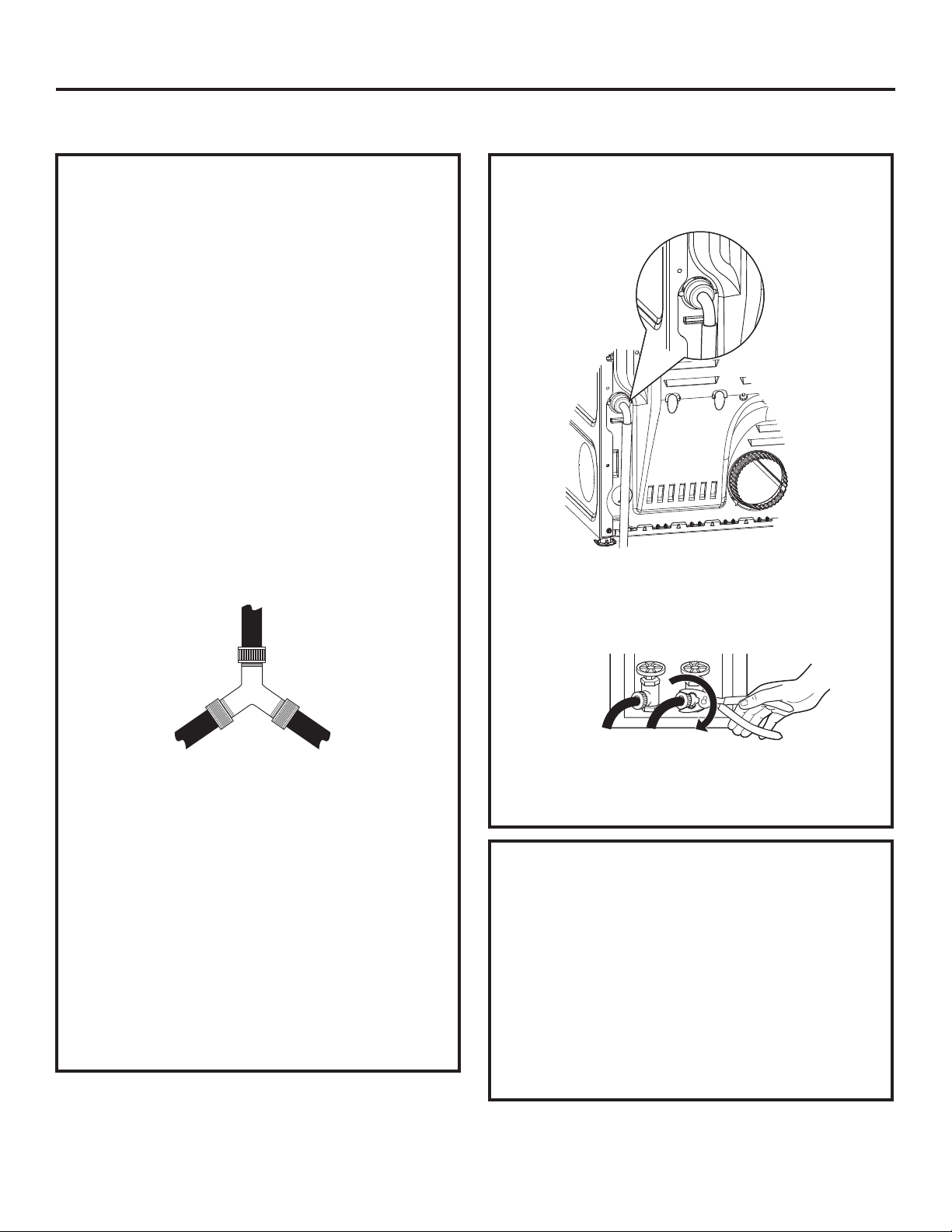
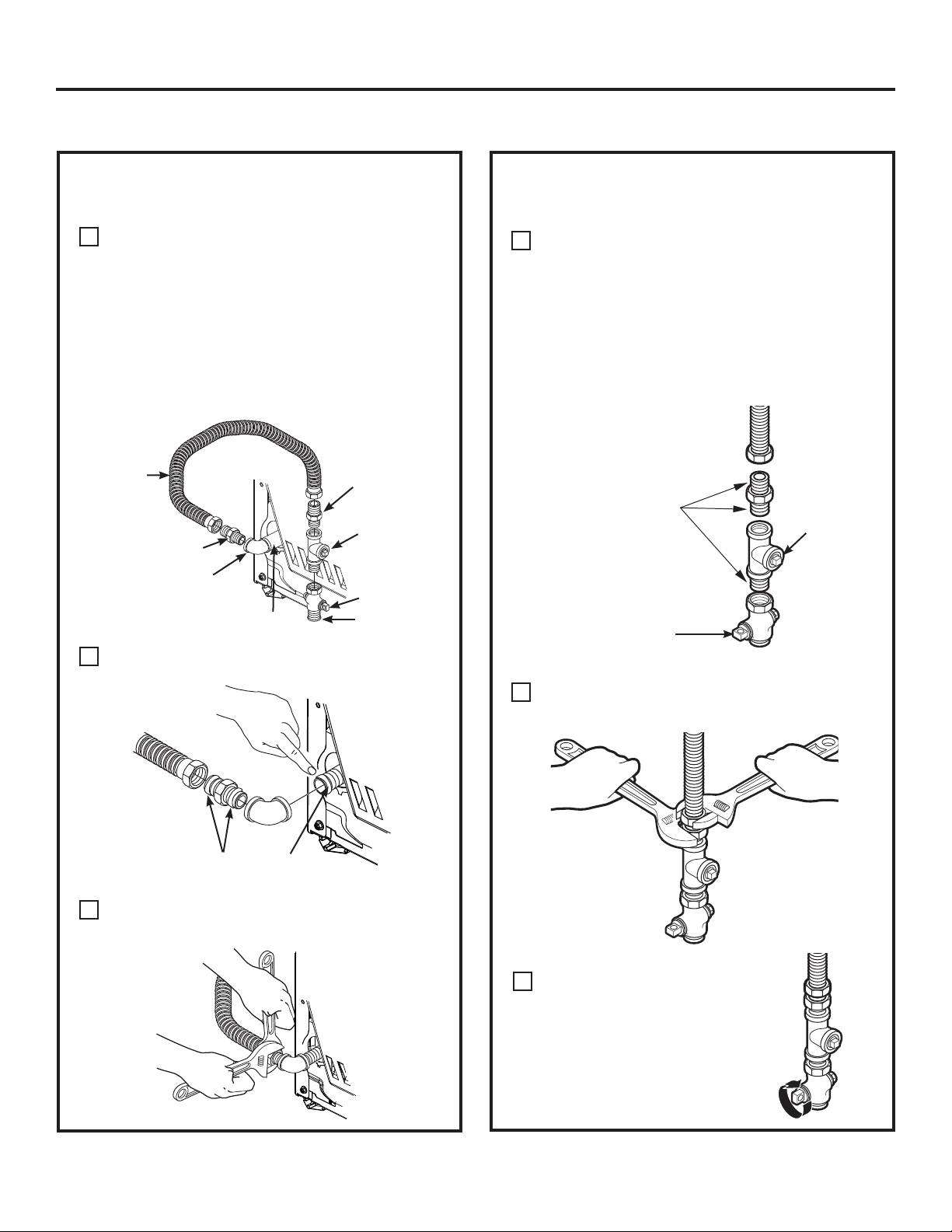
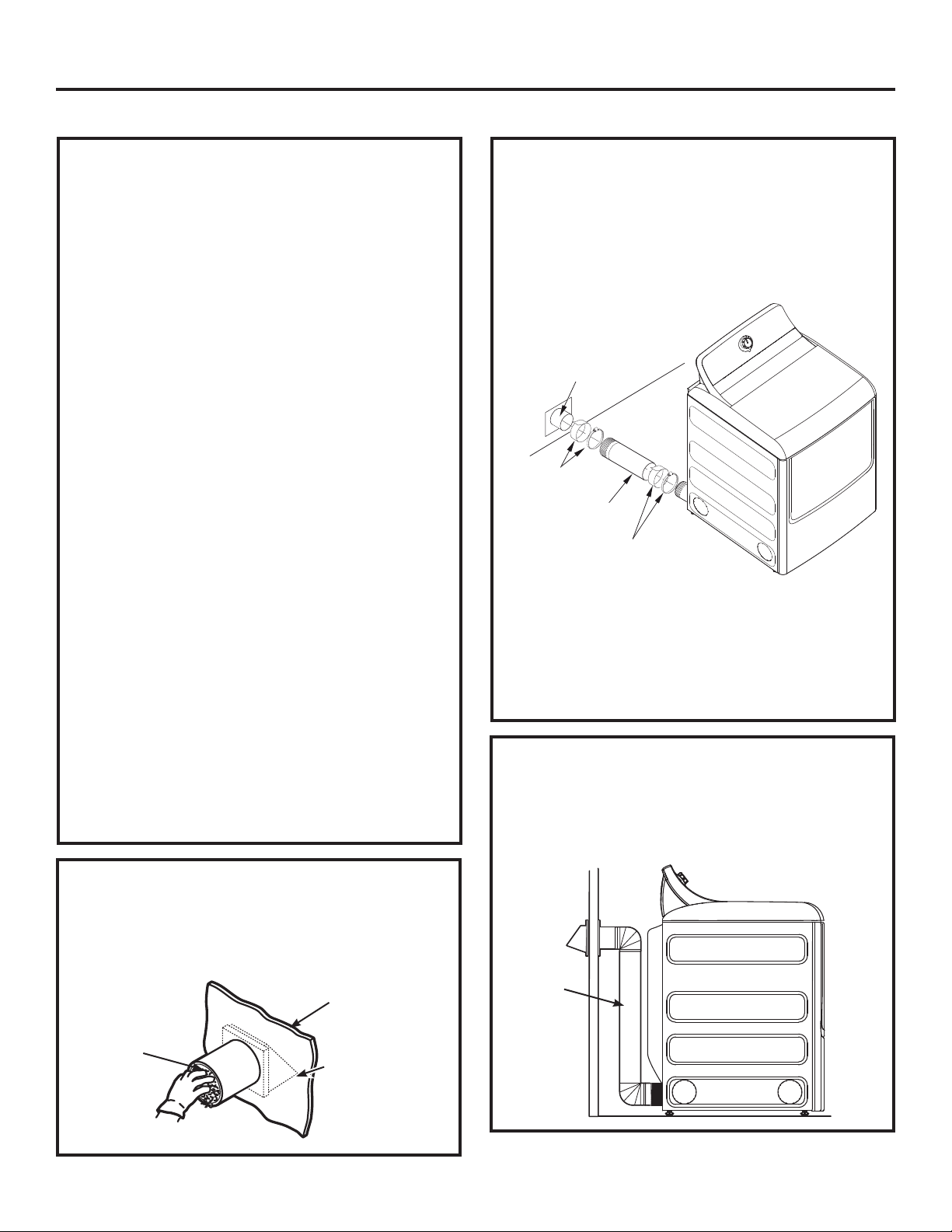
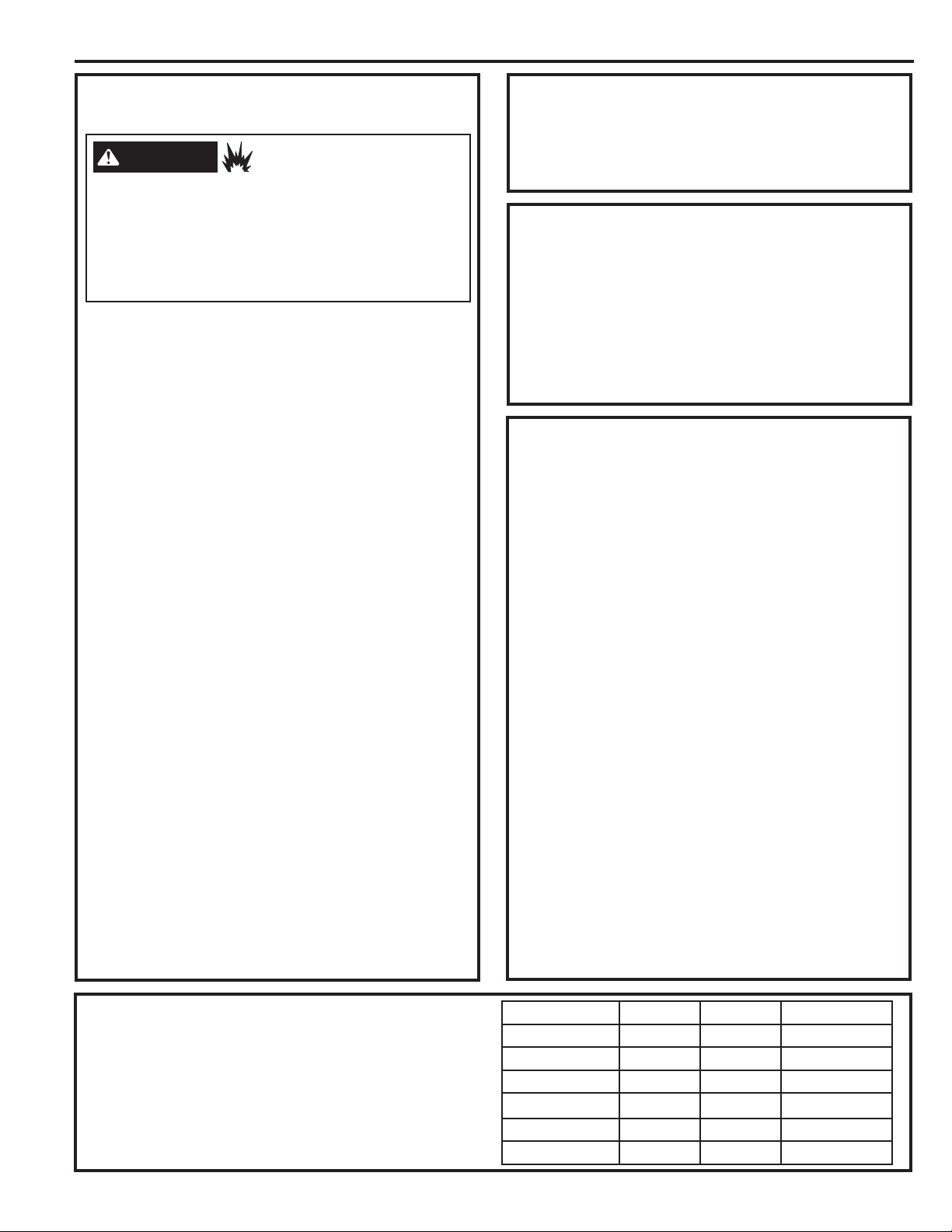
To produce steam, the dryer must connect to
the cold water supply. Since the washer must
also connect to the cold water, a “Y” connector
is inserted to allow both inlet hoses to make that
connection at the same time.
NOTE: Use the new inlet hoses provided; never use
old hoses.
17XUQ WKH FROG ZDWHU IDXFHW RII 5HPRYH WKH
washer inlet hose from the washer fill valve
connector (cold).
2. Ensure the rubber flat washer is in place and
attach one female coupling of the short hose
onto the washer fill valve connector. Tighten by
hand until firmly seated.
3. Attach one male end of the “Y” connector to the
other female coupling of the short hose. Ensure
the rubber flat washer is in place. Tighten by
hand until firmly seated.
4. Insert the filter screen in the coupling of the
washer’s inlet hose. If a rubber flat washer is
already in place remove it before installing the
filter screen. Attach this coupling to one male end
of the ‘’Y’’ connector. Tighten by hand until firmly
seated.
5. Ensure the rubber flat washer is in place and
attach the dryer’s long inlet hose to one male
end of the ‘’Y’’ connector. Tighten by hand until
firmly seated.
6. Ensure the rubber flat washer is in place and
attach the other end of the dryer’s long inlet
hose to the fill valve connector at the bottom of
the dryer back panel. Tighten by hand until firmly
seated.
4
Installation Instructions
CONNECTING INLET HOSES
7. Using pliers, tighten all the couplings with an
DGGLWLRQDOWZR²WKLUGVWXUQ
NOTE: Do not overtighten. Damage to the couplings
may result.
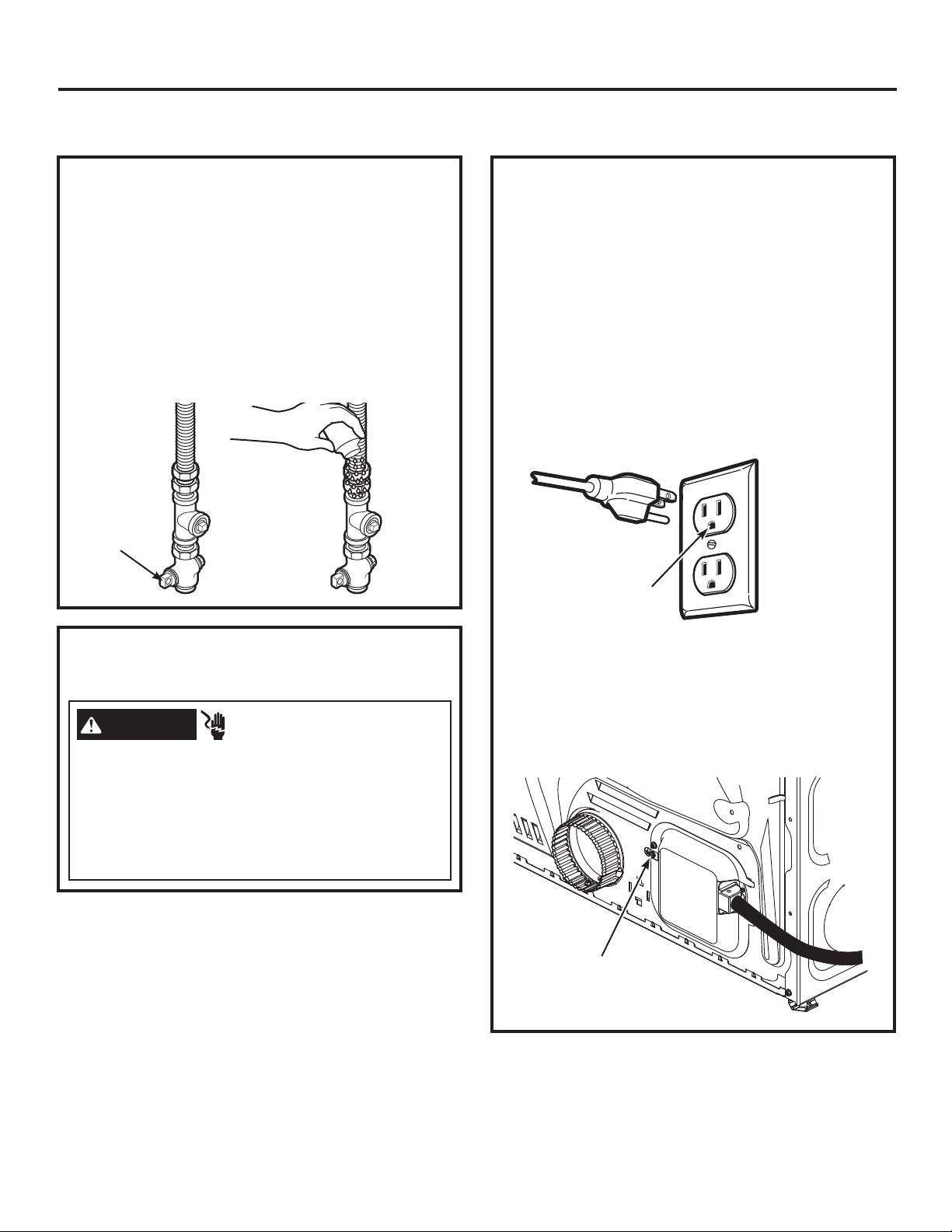
8. Turn the water faucet on.
9. Check for leaks around the ‘’Y’’ connector, faucet
and hose couplings.
WATER SUPPLY REQUIREMENTS
Hot and cold water faucets MUST be installed
within 42 in. (107 cm) of your washer’s water
inlet. The faucets MUST be 3/4 in. (1.9 cm) garden
hose-type so inlet hoses can be connected. Water
pressure MUST be between 10 and 120 pounds
per square inch. Your water department can
advise you of your water pressure.
NOTE: A water softener is recommended to reduce
buildup of scale inside the steam generator if the
home water supply is very hard.
CONNECTING INLET HOSES
(on some models)
CONNECTING INLET HOSES
(on some models) (cont.)
Installation Instructions
5
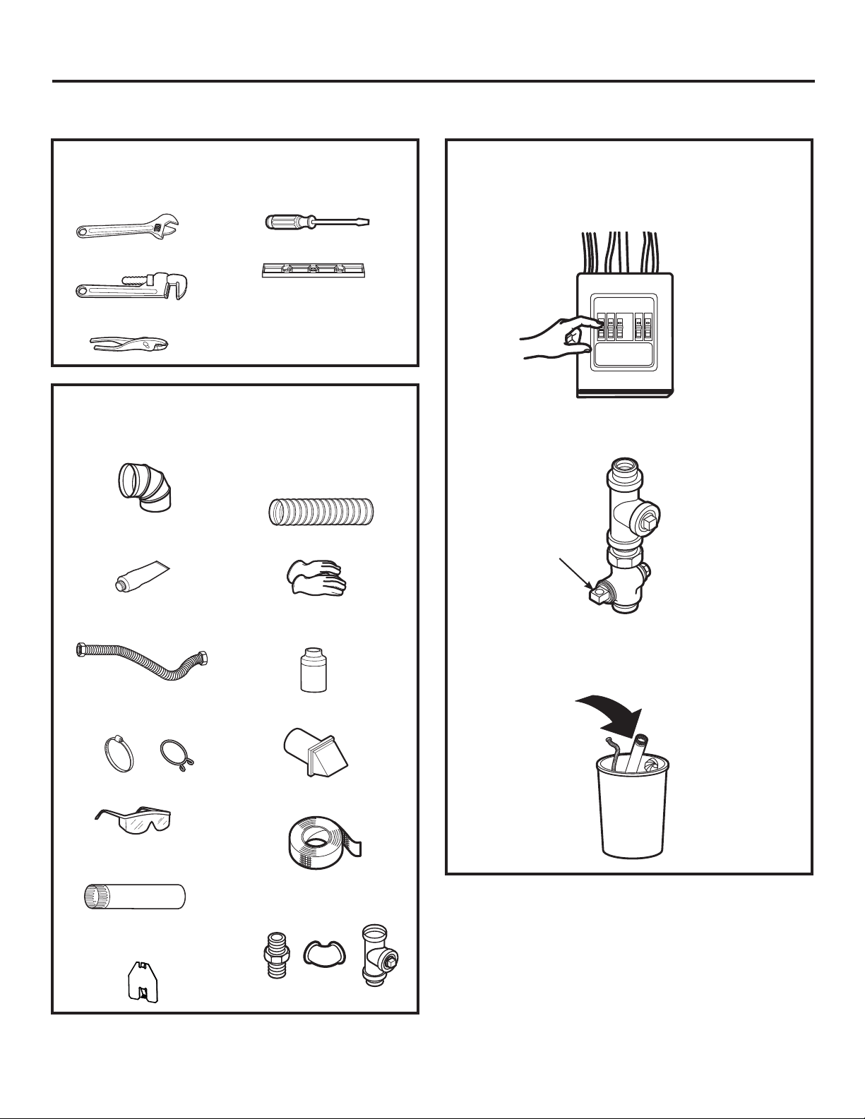
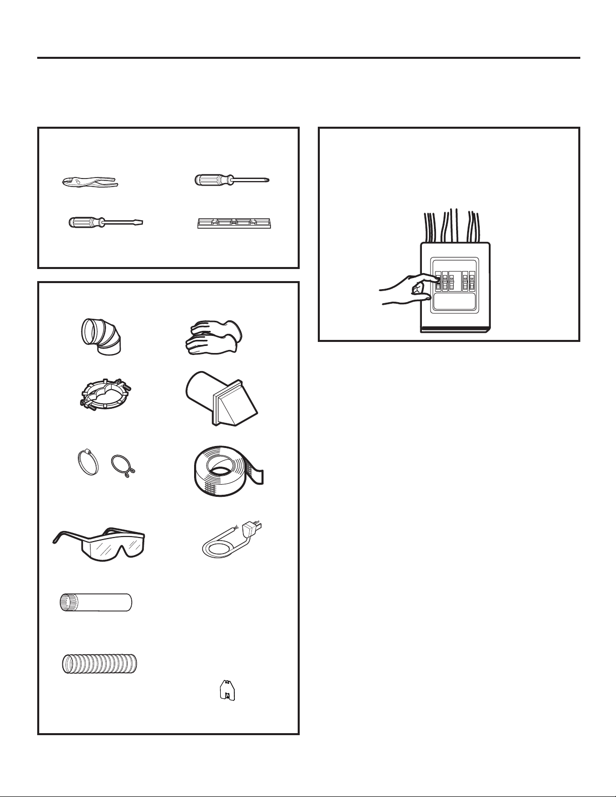
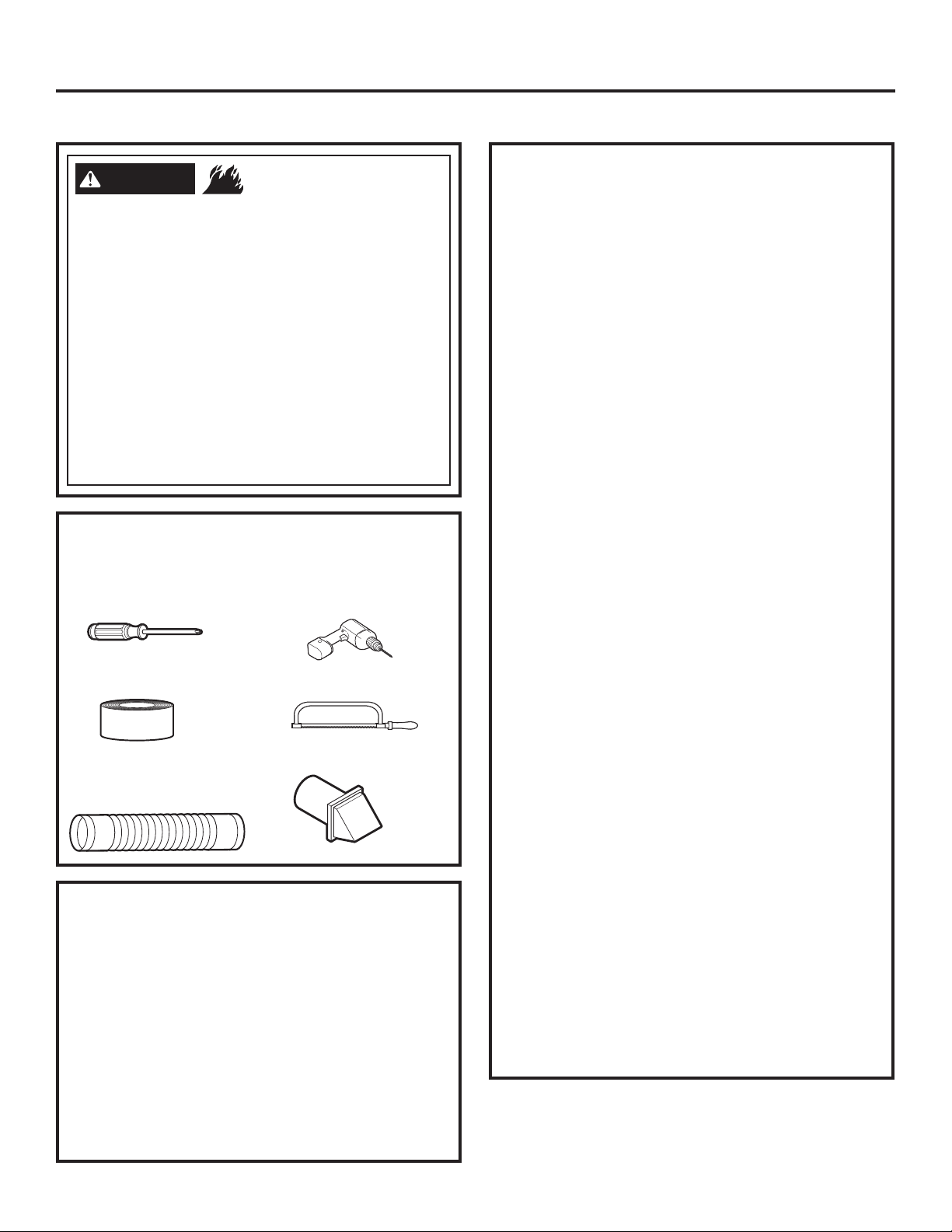
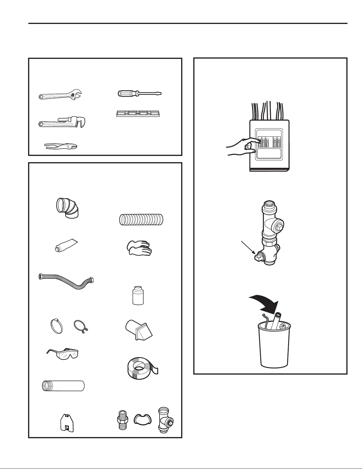
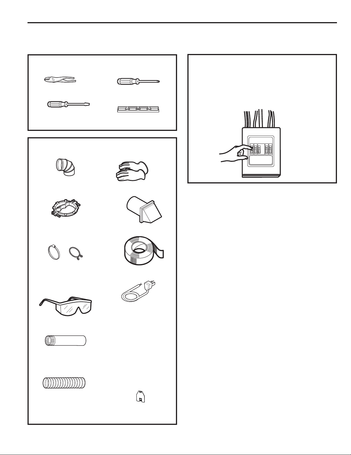
TOOLS YOU WILL NEED
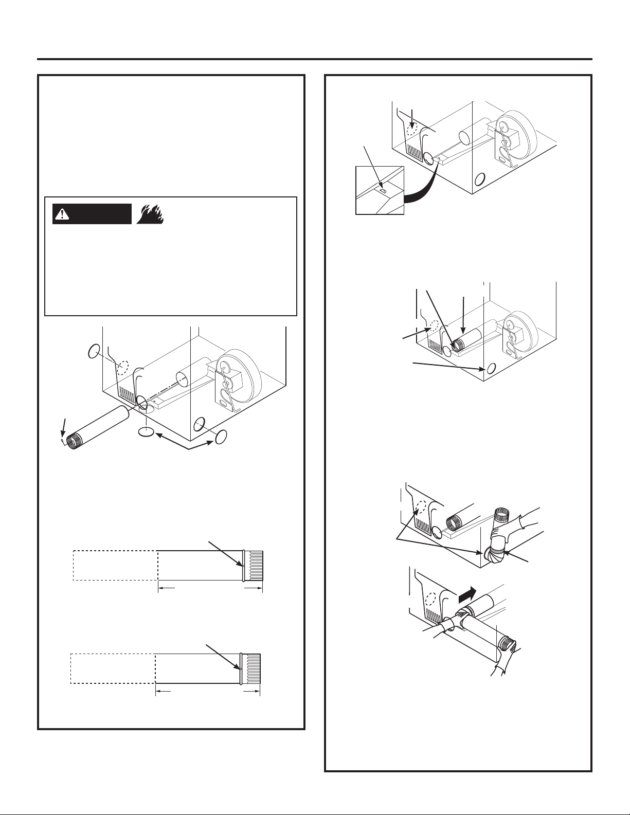
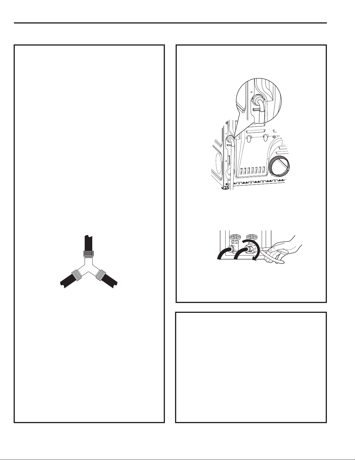
CONNECTING A GAS DRYER (skip for electric dryers)
Before beginning the installation, turn off
the circuit breaker(s) or remove the dryer’s circuit
fuse(s) at the electrical box. Be sure the dryer cord
is unplugged from the wall.
Turn the dryer’s gas shut-off valve in the supply
line to the OFF position.
Disconnect and discard old flexible gas connector
and ducting material.
Shut-off
Valve
MATERIALS YOU WILL NEED
10” Adjustable
wrenches (2)
8” Pipe wrench
Flat-blade
screwdriver
Level
Slip-joint pliers
4” dia. metal elbow
Pipe compound or
PTFE tape
Flexible gas line
connector
Duct clamps (2) or
Spring clamps (2)
Safety glasses
4” dia. metal duct
(recommended)
4” Cover Plate (Kit
WE1M454)
4” dia., UL-listed
flexible metal duct
(if needed)
Gloves
Soap solution for
leak detection
Exhaust hood
Duct tape
Gas pipe adapters (2),
elbow and pipe plug
<RXPXVWXVHZLWKWKLVGU\HUDIOH[LEOHPHWDO
connector (listed connector ANSI Z21.24/CSA 6.10).
The length of the connect shall not exceed 3 ft.
Installation Instructions
6
CONNECTING A GAS DRYER (skip for electric dryers) (cont.)
GAS REQUIREMENTS
DRYER GAS SUPPLY CONNECTION
GAS SUPPLY
A 1/8” National Pipe Taper thread plugged
tapping, accessible for test gauge connection,
must be installed immediately upstream of the
gas supply connection to the dryer. Contact
your local gas utility should you have questions
on the installation of the plugged tapping.
Supply line is to be 1/2” rigid pipe and equipped
with an accessible shutoff within 6 feet of, and
in the same room with, the dryer.
Use pipe thread compound appropriate for
natural or LP gas or use PTFE tape.
Connect flexible metal connector to dryer and
gas supply.
The installation must conform with local codes,
or in the absence of local codes, with the
National Fuel Gas Code, ANSI Z223.1/NFPA 54,
or the Natural Gas and Propane Installation
Code, CSA B149.1.
IN THE COMMONWEALTH OF
MASSACHUSETTS
This product must be installed by a licensed
plumber or gas fitter.
When using ball-type gas shut-off valves, they
shall be the T-handle type.
A flexible gas connector, when used, must not
exceed 3 feet.
ADJUSTING FOR ELEVATION
Gas clothes dryers input ratings are based on
sea level operation and need not be adjusted
for operation at or below 2000 ft. elevation. For
operation at elevations above 2000 ft., input
ratings should be reduced at a rate of 4 percent
for each 1000 ft. above sea level.
Installation must conform to local codes and
ordinances or, in their absence, the NATIONAL
FUEL GAS CODE, ANSI Z223.
- Explosion Hazard
WARNING
Use a new CSA International approved flexible
gas supply line. Never reuse old flexible
connectors.
,QVWDOODVKXWRIIYDOYH
6HFXUHO\WLJKWHQDOOJDVFRQQHFWLRQV
,IFRQQHFWHGWR/3JDVKDYHDTXDOLILHGSHUVRQ
make sure gas pressure does not exceed 13”
water column.
([DPSOHVRIDTXDOLILHGSHUVRQLQFOXGHOLFHQVHG
heating personnel, authorized gas company
personnel, and authorized service personnel.
)DLOXUHWRGRVRFDQUHVXOWLQGHDWKH[SORVLRQ
or fire.
1-7/8"
3-1/8"
3/8" NPT MALE THREAD GAS SUPPLY
NOTE: Add to vertical dimension
the distance between cabinet
bottom to floor.
This gas dryer is equipped with a valve and
burner assembly for use only with natural gas.
Using conversion kit WE25X217, your local service
organization can convert this dryer for use with
propane (LP) gas. (To convert from propane (LP)
to natural gas, conversion kit WE25X218 will be
XWLOL]HG$//&219(56,2160867%(0$'(%<
3523(5/<75$,1('$1'48$/,),('3(56211(/
$1',1$&&25'$1&(:,7+/2&$/&2'(6$1'
25',1$1&(5(48,5(0(176
Installation Instructions
7
Install a 1/8” NPT plugged tapping to the dryer
gas line shut-off valve for checking gas inlet
pressure.
Install a flare union adapter to the plugged
tapping.
NOTE: Apply pipe compound or PTFE tape
to the threads of the adapter and plugged
tapping.
Attach the flexible metal gas line connector to
the adapter.
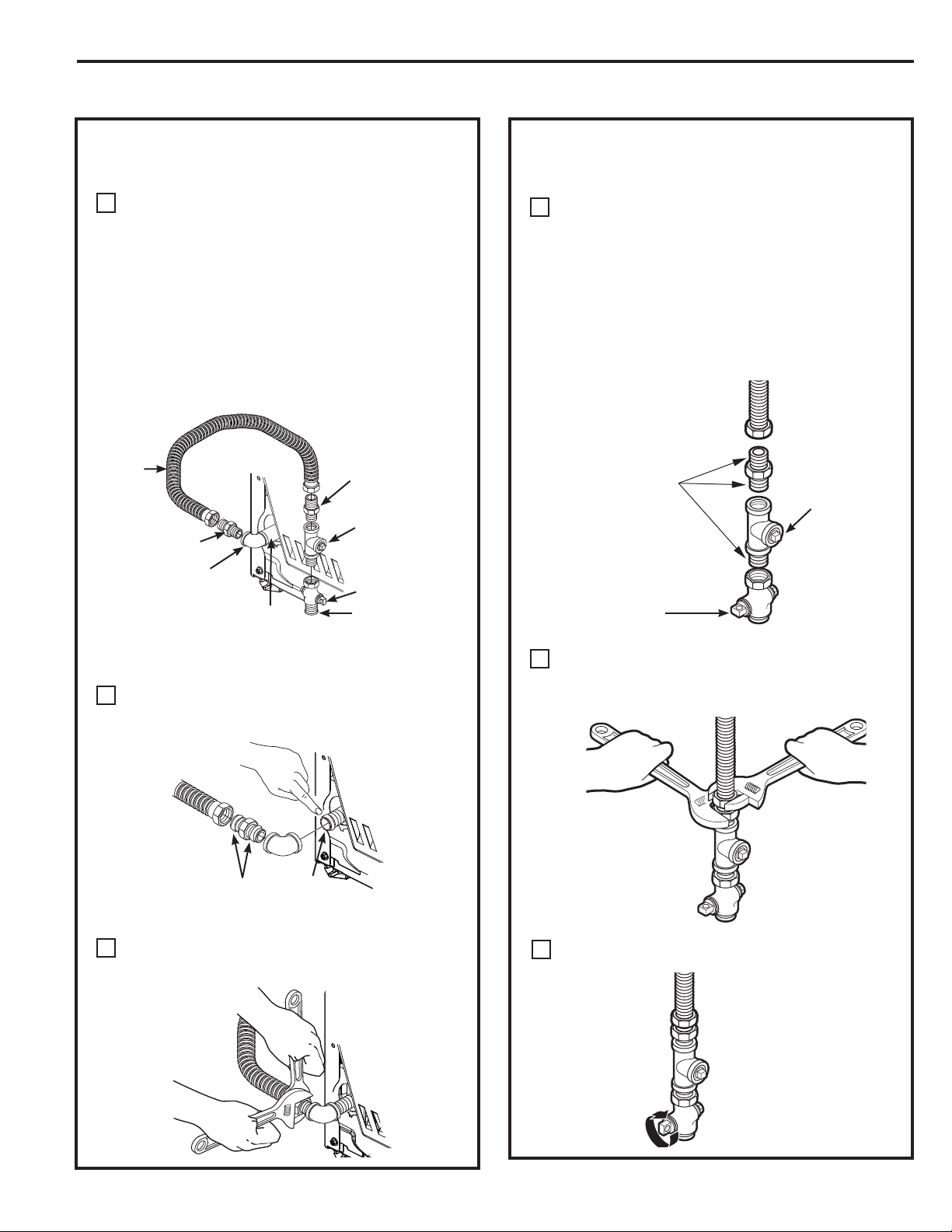
B
Tighten the flexible gas line connection, using
two adjustable wrenches.
C
D
Tighten all connections, using two adjustable
wrenches. Do not overtighten.
E
CONNECTING THE DRYER TO THE GAS
SUPPLY (cont.)
Open the gas shut-off valve.
F
Apply pipe compound
or PTFE tape to all
male threads.
Shut-Off
Valve
Plugged
Tapping
CONNECTING THE DRYER TO THE GAS
SUPPLY
Install a female 3/8” NPT elbow at the end of the
dryer gas inlet.
Install a 3/8” flare union adapter to the female
elbow.
IMPORTANT: Use a pipe wrench to securely hold
on to the end of the dryer gas inlet to prevent
twisting the inlet.
NOTE: Apply pipe compound or PTFE tape to the
threads of the adapter and dryer gas inlet.
A
Elbow
Adapter
Items not supplied
Adapter
1/8” NPT
Pipe Plug for
Checking Gas
Inlet Pressure
Shut-Off Valve
Pipe size at
least 1/2”
3/8” NPT
New Metal
Flexible Gas
Line Connector
Apply pipe compound to the
adapter and dryer gas inlet
Installation Instructions
8
CONNECTING A GAS DRYER (skip for electric dryers) (cont.)
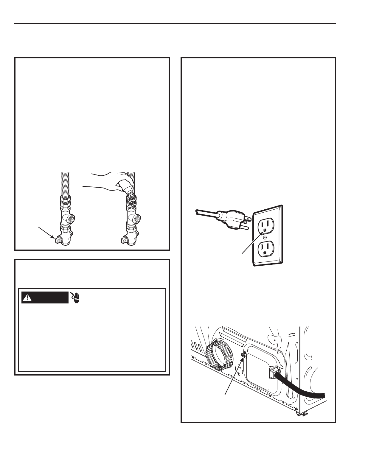
TEST FOR LEAKS
Never use an open flame to test for gas leaks.
Check all connections for leaks with soapy solution
or equivalent.
Apply a soap solution. The leak test solution must
not contain ammonia, which could cause damage
to the brass fittings.
If leaks are found, close the valve, retighten the
joint and repeat the soap test.
Open Gas
Valve
Ensure proper
ground exists
before use.
ELECTRICAL CONNECTION
INFORMATION FOR GAS DRYERS (cont.)
The dryer must be electrically grounded in
accordance with local codes, or in the absence of
local codes, with the National Electrical Code, ANSI/
NFPA 70 or Canadian Electrical Code, CSA C22.1
This appliance must be supplied with 120V, 60Hz,
and be connected to a properly grounded branch
circuit protected by a 15 or 20 amp circuit breaker
or time delay fuse. If electrical supply provided
does not meet these requirements, it is the owner’s
responsibility to have a licensed electrician install a
properly grounded 3-prong outlet.
If local codes permit an external ground wire
(not provided) may be added by attaching to the
green ground screw on the rear of the dryer, and
to a grounded metal cold water pipe or other
established ground.
ELECTRICAL CONNECTION
INFORMATION FOR GAS DRYERS
- Electrical Shock Hazard
WARNING
Plug into a grounded 3 prong outlet.
DO NOT remove ground prong.
DO NOT use an adapter.
DO NOT use an extension cord.
Failure to do so can result in death, fire or electrical
shock.
Ground
Screw
Installation Instructions
CONNECTING AN ELECTRIC DRYER
(Skip for gas dryers and if your dryer already has a power cord attached)
Before making the electrical connection, turn off
the circuit breaker(s) or remove the dryer’s circuit
fuse(s) at the electrical box. Be sure the dryer cord
is unplugged from the wall.
1(9(5/($9(7+(
$&&(66&29(52))7+(7(50,1$/%/2&.
Slip-joint pliers
Flat-blade crewdriver
Phillips screwdriver
Level
TOOLS YOU WILL NEED
MATERIALS YOU WILL NEED
4” dia. metal elbow
3/4” strain relief
(UL recognized)
4”duct
clamps (2) or
4”spring clamps (2)
Safety glasses
4” dia. metal duct
(recommended)
4” dia., UL-listed
flexible metal duct
(if needed)
Gloves
Exhaust hood
Duct tape
Dryer power cord kit
(not provided with
dryer)
UL rated 120/240V,
30A with 3 or 4 prongs.
Identify the plug type
as per the house
receptacle before
purchasing line cord.
4” Cover Plate (Kit
WE1M454)
9
CONNECTING AN ELECTRIC DRYER (cont.)
(Skip for gas dryers and if your dryer already has a power cord attached)
Installation Instructions
ELECTRICAL CONNECTION
INFORMATION FOR ELECTRIC DRYERS
- Fire Hazard
WARNING
Use a new UL-listed 240V 30 amp dryer power supply
cord with closed ring terminals or spade terminals with
upturned ends.
Use a UL-listed strain relief.
Disconnect power before making electrical
connections.
Connect neutral wire (white or center wire) to center
terminal.
Ground wire (green or bare wire) must be connected to
green ground connector.
Connect remaining two supply wires to remaining two
terminals.
Securely tighten all electrical connections.
5HSODFHWKHWHUPLQDOEORFNFRYHU
Failure to do so can result in death, fire or electrical
shock.
For electrical connections using a
power cord:
ELECTRICAL CONNECTION
INFORMATION FOR ELECTRIC DRYERS
For direct wire connections:
- Fire Hazard
WARNING
Use 10 gauge copper wire.
Use a UL-listed strain relief.
Disconnect power before making electrical
connections.
Connect neutral wire (white or center wire) to center
terminal.
Ground wire (green or bare wire) must be connected to
green ground connector.
Connect remaining two supply wires to remaining two
terminals.
Securely tighten all electrical connections.
5HSODFHWKHWHUPLQDOEORFNFRYHU
Failure to do so can result in death, fire or electrical
shock.
GROUNDING INSTRUCTIONS
For a grounded, cord-connected dryer: This dryer
must be grounded. In the event of a malfunction
or breakdown, grounding will reduce the risk
of electric shock by providing a path of least
resistance for electric current. This dryer uses a
cord having an equipment-grounding conductor
and a grounding plug. The plug must be plugged
into an appropriate outlet that is properly installed
and grounded in accordance with all local codes
and ordinances.
WARNING
Improper connection of the
equipment-grounding conductor
can result in a risk of electrical shock. Check with a
qualified electrician, or service representative or
personnel, if you are in doubt as to whether the
appliance is properly grounded. DO NOT modify the
plug on the power supply cord. If it will not fit the
outlet, have a proper outlet installed by a qualified
electrician.
SAVE THESE INSTRUCTIONS
GROUNDING INSTRUCTIONS
For a permanently connected dryer: This
dryer must be connected to a grounded metal,
permanent wiring system, or an equipment-
grounding conductor must be run with the circuit
conductors and connected to the equipment-
grounding terminal on the appliance.
WARNING
Improper connection of the
equipment-grounding conductor
can result in a risk of electrical shock. Check with a
qualified electrician, or service representative or
personnel, if you are in doubt as to whether the
appliance is properly grounded.
SAVE THESE INSTRUCTIONS
10
Installation Instructions
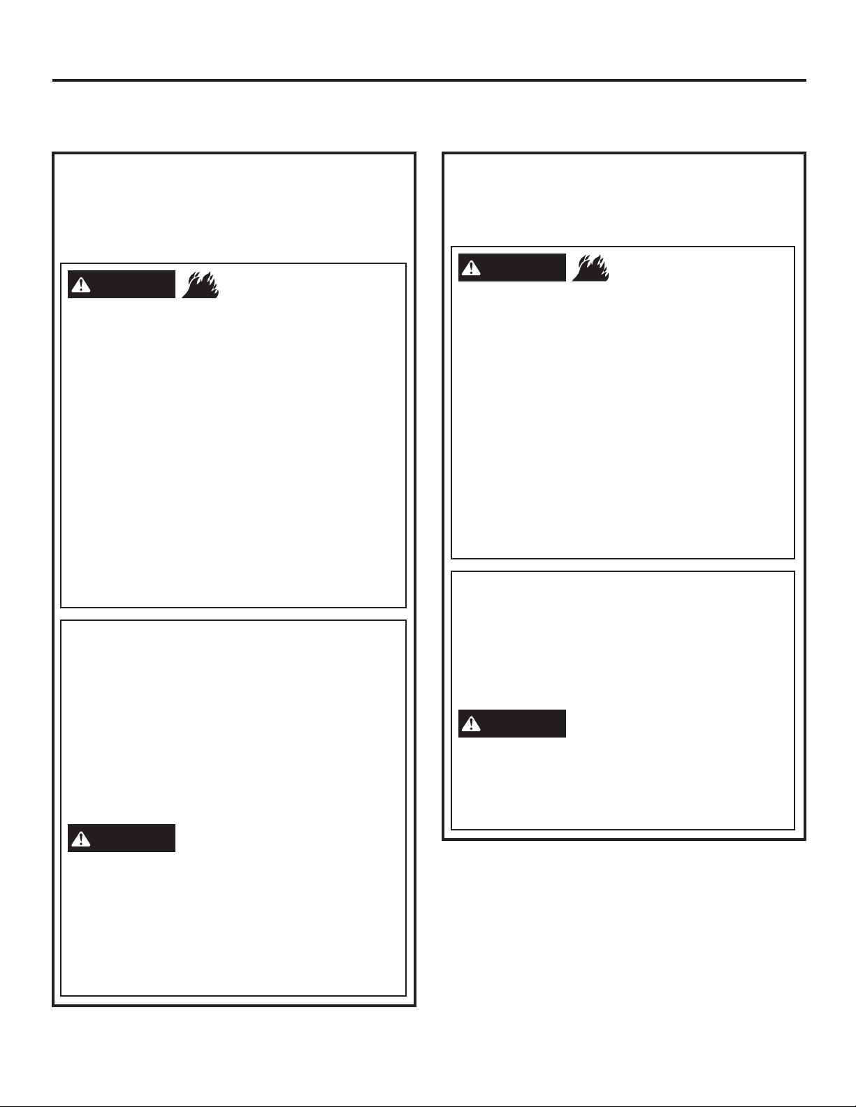
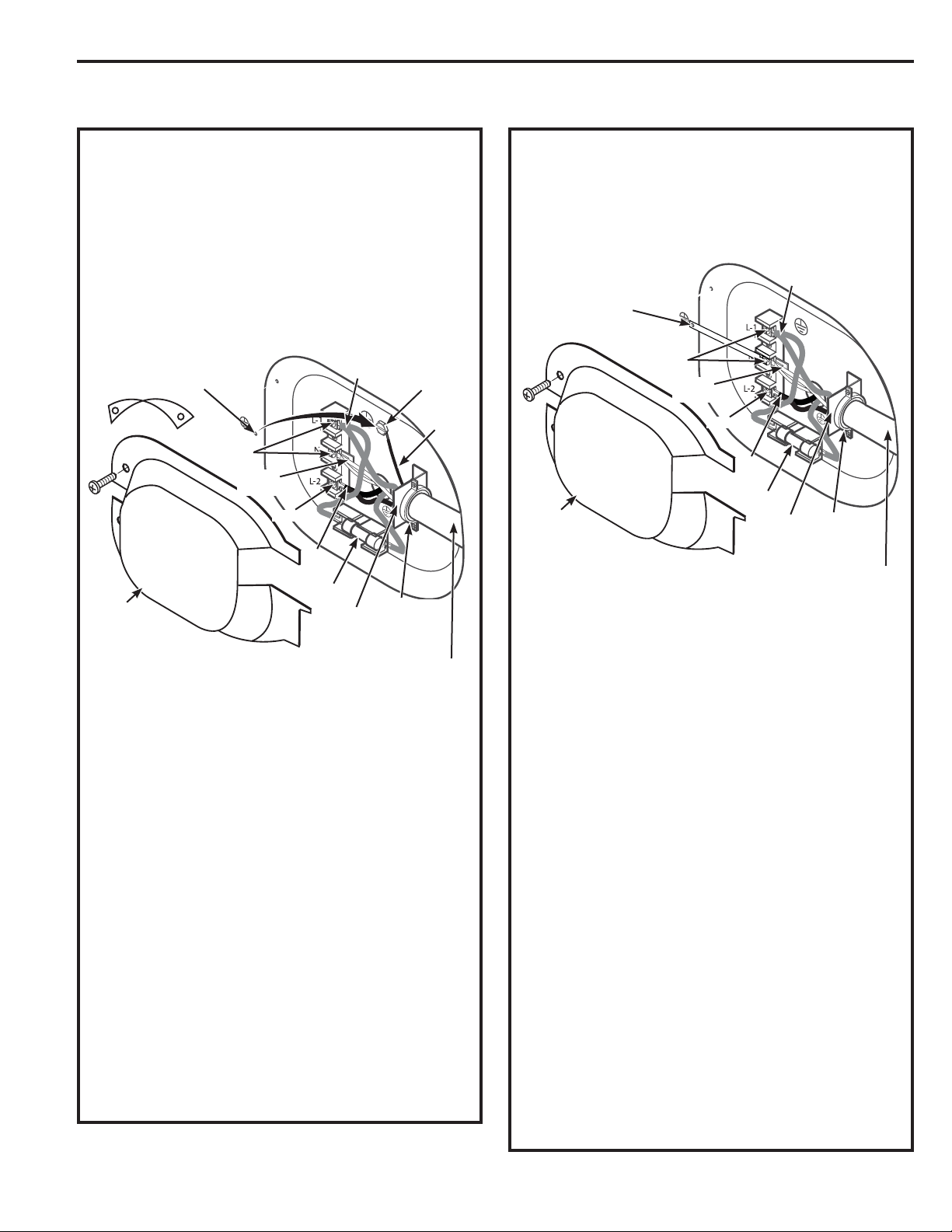
CONNECTING DRYER USING 3-WIRE
CONNECTION
1. Turn off the circuit breaker(s) (30 amp) or remove the
dryer’s circuit fuse at the electrical box.
2. Be sure the dryer cord is unplugged from the wall
receptacle.
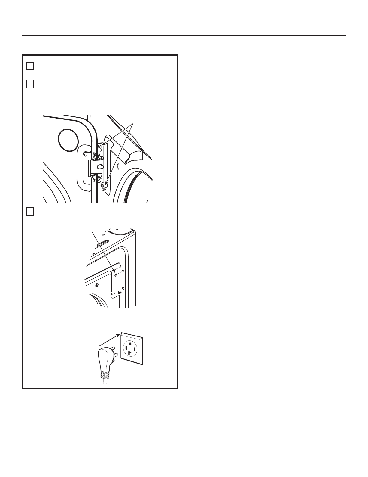
3. 5HPRYHWKHSRZHUFRUGFRYHUORFDWHGDWWKHORZHU
back.
4. Install 3/4-in. UL-recognized strain relief to power
cord entry hole. Bring power cord through strain
relief.
5. Connect power cord as follows:
A. Connect the 2 hot lines to the outer screws of the
terminal block (marked L1 and L2).
B. Connect the neutral (white) line to the center of the
terminal block (marked N).
6. Be sure ground strap is connected to neutral (center)
terminal of block and to green ground screw on
cabinet rear. Tighten all terminal block screws (3)
securely.
7. Properly secure power cord to strain relief.
8.5HLQVWDOOWKHFRYHU
3-wire Connection
Not for use in Canada.
DO NOT use for Mobile Home Installations.
NOT for use on new construction.
NOT for use on recreational vehicles.
NOT for use in areas where local codes prohibit
grounding through the neutral conduction.
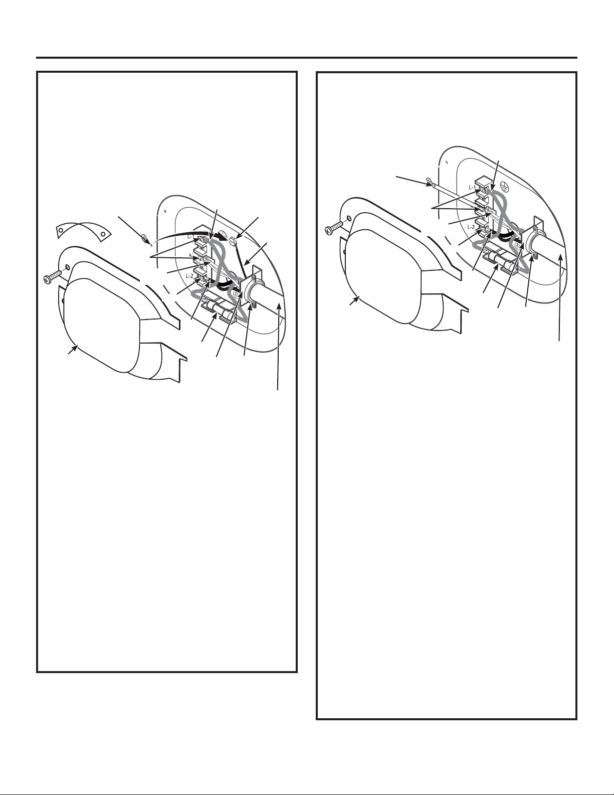
CONNECTING DRYER USING 4-WIRE
CONNECTION (MUST BE USED FOR
MOBILE HOME INSTALLATION)
NOTE: Since January 1, 1996, the National Electrical Code
requires that new constructions use a 4-wire connection
to an electric dryer. A 4-wire cord must also be used where
local codes do not permit grounding through the neutral.
3-wire connection is NOT for use on new construction.
11
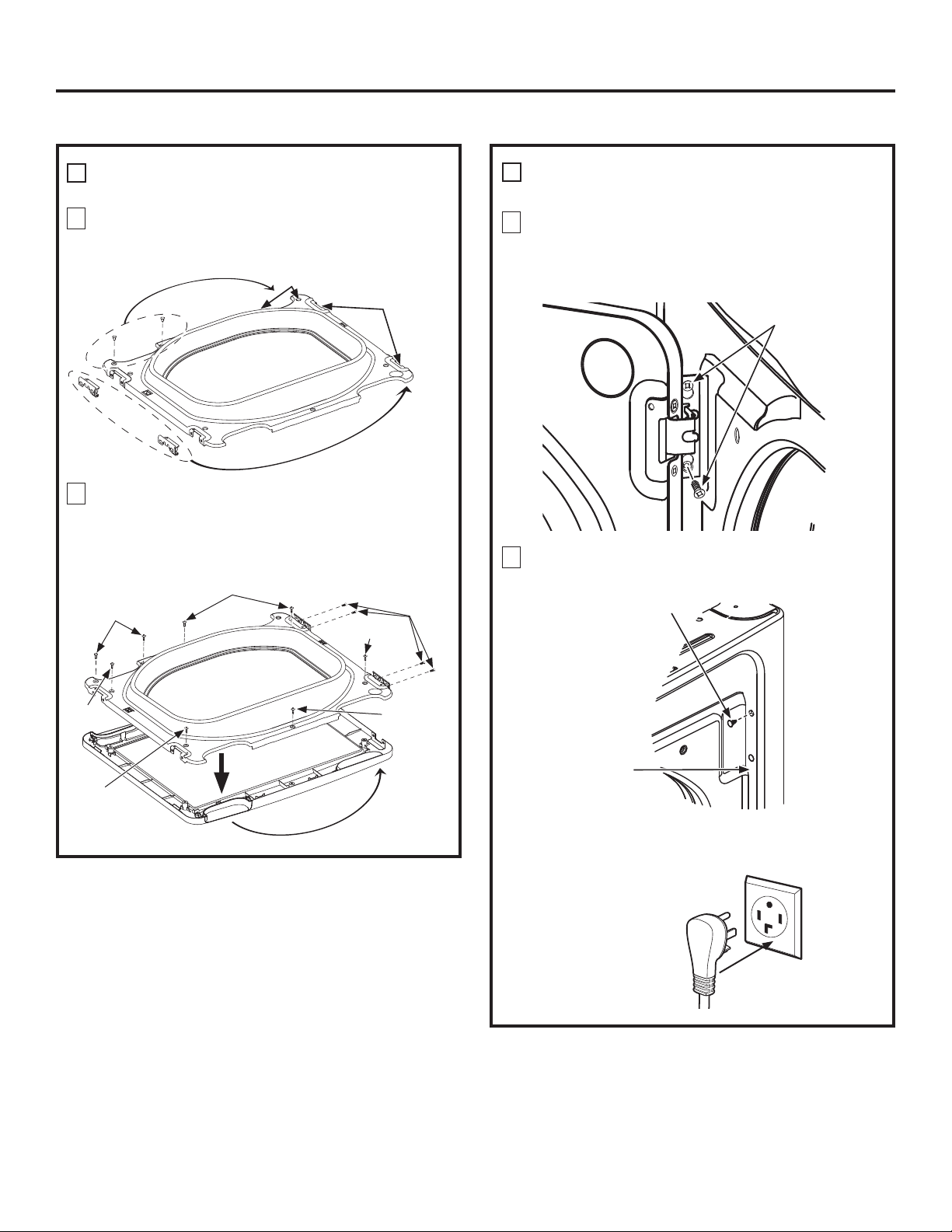
1. Turn off the circuit breaker(s) (30 amp) or remove the
dryer’s circuit fuse at the electrical box.
2. Be sure the dryer cord is unplugged from the wall
receptacle.
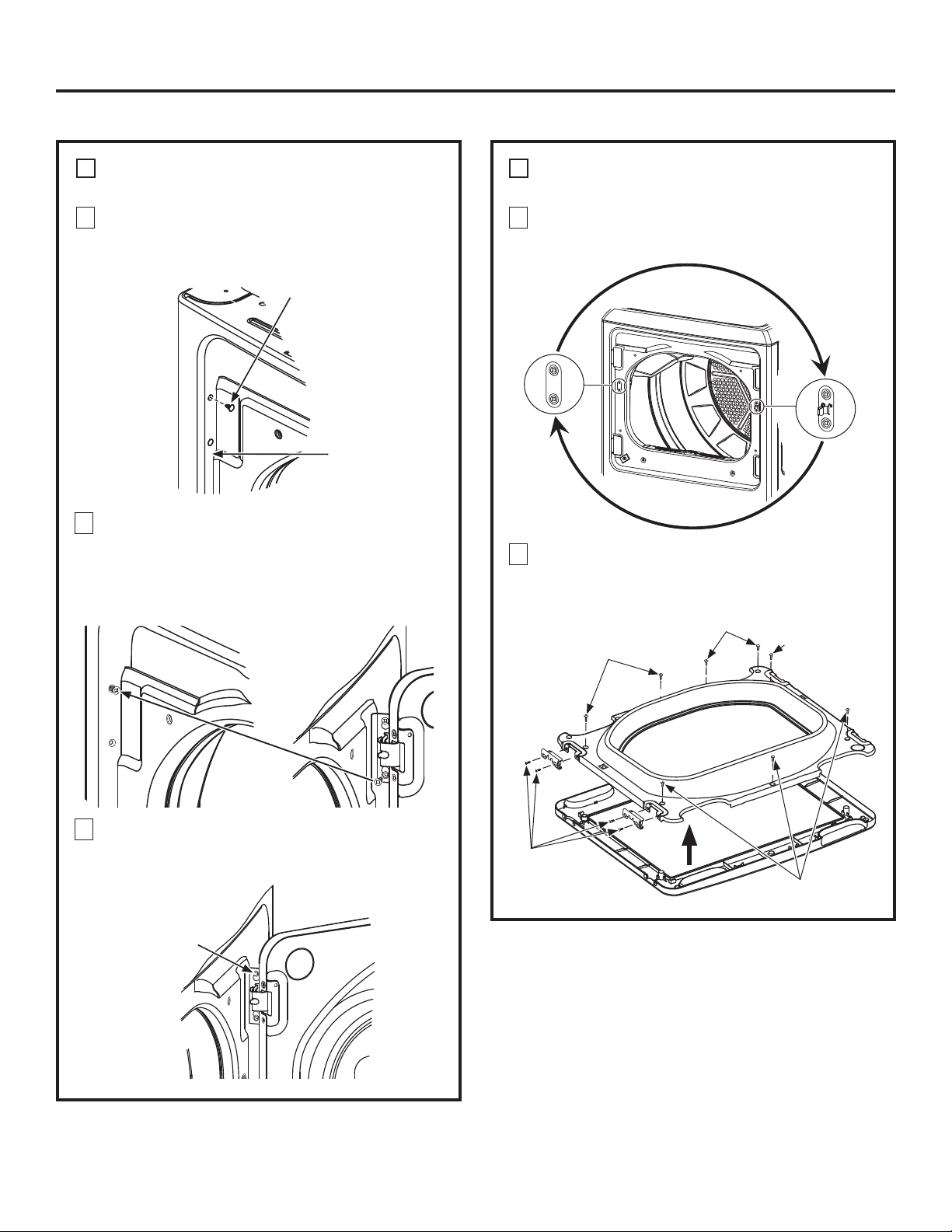
3. 5HPRYHWKHSRZHUFRUGFRYHUORFDWHGDWWKHORZHUEDFN
4.5HPRYHDQGGLVFDUGJURXQGVWUDS.HHSWKHJUHHQ
ground screw for Step 7.
5. Install 3/4 in. UL-recognized strain relief to power cord
entry hole. Bring power cord through strain relief.
6. Connect power cord as follows:
A. Connect the 2 hot lines to the outer screws of the
terminal block (marked L1 and L2).
B. Connect the neutral (white) line to the center of the
terminal block (marked N).
7. Attach ground wire of power cord with the green
ground screw (hole above strain relief bracket). Tighten
all terminal block screws (3) securely.
8. Properly secure power cord to strain relief.
9.5HLQVWDOOWKHFRYHU
NEVER LEAVE THE COVER OFF OF THE TERMINAL
BLOCK.
NEVER LEAVE THE COVER OFF OF THE TERMINAL
BLOCK.
If required, by local code, install external ground (not
provided) to grounded metal, cold water pipe, or other
established ground determined by a qualified electrician.
Screws
(2)
5HPRYHJURXQGVWUDS
and discard. Keep
green ground screw
Hot
Wire
5HORFDWH
green
ground
screw
here
Green
Wire
3/4” UL
5HFRJQL]HG
6WUDLQ5HOLHI
4 #10 AWG minimum copper conductors or 120/240V 30A power supply
cord kit marked for use with dryers and provided with closed loop or
spade terminals with upturned ends (not supplied).
Fuse
Hot
Wire
Neutral
(white)
Strain
5HOLHI
Bracket
Cover
Screw
Screws
(2)
Hot
Wire
3/4” UL
5HFRJQL]HG
6WUDLQ5HOLHI
3 #10 AWG minimum copper conductors or 120/240V 30A power supply
cord kit marked for use with dryers and provided with closed loop or
spade terminals with upturned ends (not supplied).
Fuse
Hot
Wire
Neutral
(white)
Strain
5HOLHI
Bracket
Cover
Screw
Green Ground Screw
& Ground Strap
Installation Instructions
EXHAUSTING THE DRYER
- Fire Hazard
WARNING
This dryer MUST be vented to the outdoors.
Use only 4” rigid metal ducting for the home
exhaust vent.
Use only 4” rigid metal or UL-LISTED transition duct
to connect the dryer to the home exhaust duct.
DO NOT use a plastic vent.
DO NOT exhaust into a chimney, kitchen exhaust,
gas vent, wall, ceiling, attic, crawl space, or
concealed space of a building.
DO NOT install a screen in or over the exhaust duct.
DO NOT use duct longer than specified in the
exhaust length table.
Failure to follow these instructions can result in
death or fire.
12
CONNECTING THE DRYER TO HOUSE
VENT
RIGID METAL TRANSITION DUCT
For best drying performance, a rigid metal transition
duct is recommended.
5LJLGPHWDOWUDQVLWLRQGXFWVUHGXFHWKHULVNRIFUXVKLQJ
and kinking.
UL-LISTED FLEXIBLE METAL CLOTHES DRYER
TRANSITION DUCT
If rigid metal cannot be used, then UL-LISTED flexible
PHWDOFORWKHVGU\HUWUDQVLWLRQGXFW*(SDUWV²
PM08X10085, WX08X10085 or WX08X10077) can be
used.
Never install transition duct in walls, ceilings, floors or
other enclosed spaces.
Total length of transition duct should not exceed
8’ (2.4 m).
For many applications, installing elbows at both
the dryer and the wall is highly recommended (see
illustrations at right). Elbows allow the dryer to sit
close to the wall without kinking and/or crushing the
transition duct, maximizing drying performance.
Avoid resting the duct on sharp objects.
UL-LISTED FLEXIBLE METAL (FOIL-TYPE) TRANSITION
DUCT
In special installations, it may be necessary to connect
the dryer to the home exhaust vent using flexible metal
IRLOW\SHWUDQVLWLRQGXFW8/²/,67('XQLYHUVDOIOH[LEOH
GU\HUWUDQVLWLRQGXFW*(SDUWV²30;RU:;;
may be used ONLY in installations where rigid metal or
flexible metal transition ducting cannot be used AND
where a 4” diameter can be maintained throughout
the entire length of the transition duct.
In Canada and the United States, only transition ducts that
comply with “UL 2158A STANDARD FOR CLOTHES DRYER
TRANSITION DUCT” shall be used.
Avoid resting the duct on sharp objects.
For best drying performance:
1. Slide one end of the duct over the clothes dryer
outlet pipe.
2. Secure the duct with a clamp.
3. With the dryer in its permanent position, extend
the duct to its full length. Allow 2
”
of duct to
overlap the exhaust pipe. Cut off and remove
excess duct. Keep the duct as straight as
possible for maximum airflow.
4. Secure the duct to the exhaust pipe with the
other clamp.
TOOLS AND MATERIALS YOU WILL
NEED TO INSTALL EXHAUST DUCT
PARTS AVAILABLE FROM LOCAL
SERVICE ORGANIZATIONS
5LJLG0HWDO'XFW&RPSRQHQWV
WX8X63 4 x 1 Duct
WX8X64 4 x 2 Duct
WX8X51 4 Elbow
WX8X59 4 Aluminum Hood
Flexible Metal Duct Components
WX8X58 4 Clamps (2)
WX8X59 4 Aluminum Hood
WX08X10077 8//LVWHG)OH[LEOH0HWDO6HPL5LJLG
Duct, 2 Clamps, 2 Close Elbows
WE1M454 Cover rear exhaust opening
Phillips-head
screwdriver
Duct tape or
duct clamp
5LJLGRU8/OLVWHG
flexible metal 4”
(10.2 cm) duct
Drill with 1/8” drill bit
(for bottom venting)
Hacksaw
Vent hood
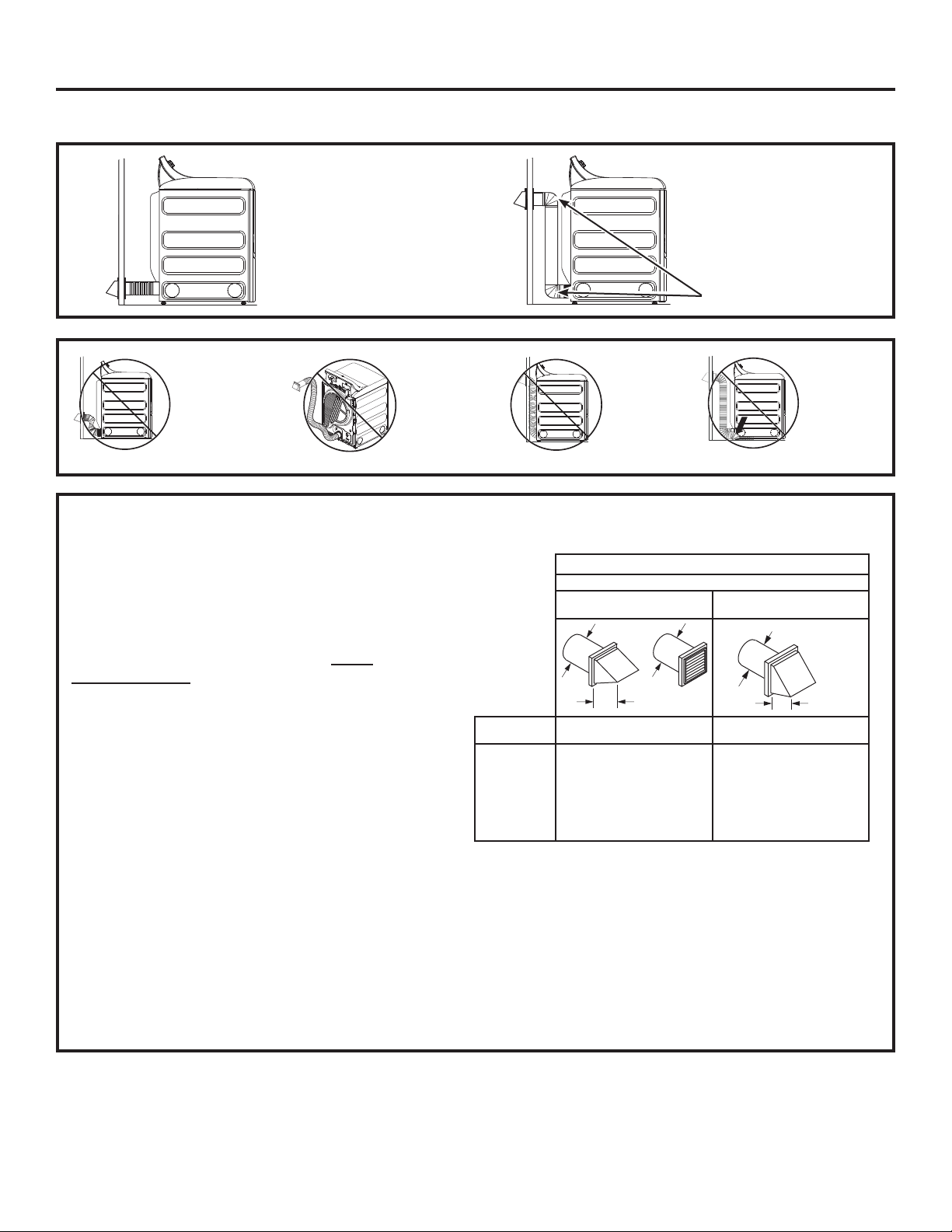
Installation Instructions
Using exhaust longer than specified length will:
Increase the drying times and the energy cost.
5HGXFHWKHGU\HUOLIH
Accumulate lint, creating a potential fire
hazard.
The correct exhaust installation is YOUR
RESPONSIBILITY.
Problems due to incorrect installation are not
covered by the warranty.
The MAXIMUM ALLOWABLE length of the exhaust
system depends upon the type of duct, number of
turns, the type of exhaust hood (wall cap) and all
conditions noted on the chart.
Internal elbows added for side or bottom vent
conversions must be included in the total elbow
count.
Any elbow greater than 45° should be treated as
a 90° elbow.
Two 45° elbows will be treated like one 90° elbow.
For every additional 90° elbow, reduce the
allowable vent system length by 10 feet.
When calculating the total vent system length,
you must add all the straight portions and
elbows of the system (including the transition
duct).
EXHAUST LENGTH
13
4" DIA.
4"
4" DIA.
4" DIA.
2-1/2"
RECOMMENDED MAXIMUM LENGTH
Exhaust Hood Types
Recommended
No. of 90°
Elbows
Rigid
Metal
Rigid
Metal
120 Feet
100 Feet
85 Feet
70 Feet
60 Feet
90 Feet
75 Feet
65 Feet
55 Feet
45 Feet
0
1
2
3
4
55 Feet 35 Feet5
Use only for short
run installations
EXHAUST LENGTH
DO NOT bend
or collapse
ducting. Use
elbows if turns
are necessary.
DO NOT use
excessive
exhaust
length. Cut
duct as short
as possible.
DO NOT
crush duct
against the
wall
.
DO NOT
set dryer
on duct
.
DO cut duct as short
as possible and install
straight into wall.
DO use elbows when
turns are necessary.
Elbows
Installation Instructions
BEFORE YOU BEGIN
5HPRYHDQGGLVFDUGH[LVWLQJSODVWLFRUPHWDOIRLO
duct and replace with UL-listed duct.
5HPRYHDQ\OLQWIURPWKHZDOOH[KDXVWRSHQLQJ
Internal
Duct
Opening
Wall
Check that exhaust
hood damper opens
and closes freely.
STANDARD REAR EXHAUST
We recommend that you install your dryer before
installing your washer. This will permit direct
access for easier exhaust connection.
Slide the end of the exhaust duct on the back of the
dryer and secure with duct tape or a duct clamp.
NOTE: We strongly recommend using rigid metal
exhaust duct. However, if flexible ducting is used it
must be UL-Listed metal, not plastic.
For straight-line installation, connect the dryer
exhaust to the wall, using duct tape or a duct
clamp.
RECOMMENDED CONFIGURATION TO
MINIMIZE EXHAUST BLOCKAGE
Using duct elbows will prevent duct kinking and
collapsing.
Transition
Ducting
14
EXHAUST SYSTEM CHECKLIST
HOOD OR WALL CAP
Terminate in a manner to prevent back drafts or entry
of birds or other wildlife.
Termination should present minimal resistance to
the exhaust airflow and should require little or no
maintenance to prevent clogging.
Wall caps must be installed at least 12” above ground
level or any other obstruction with the opening
pointed down.
SEPARATION OF TURNS
For best performance, separate all turns by at least
4 ft. of straight duct, including distance between last
turn and dampened wall cap.
SEALING OF JOINTS
All joints should be tight to avoid leaks. The male end
of each section of duct must point away from the
dryer.
Duct joints should be made air- and moisture-tight
by wrapping the overlapped joints with duct tape or
aluminum tape.
Do not assemble ductwork with any fasteners
that extend into the duct. These fasteners can
accumulate lint, creating a potential fire hazard.
Horizontal runs should slope down towards the
outdoors 1/4” per foot.
Provide an access for inspection and cleaning of
the exhaust system, especially at turns and joints.
Exhaust system shall be inspected and cleaned at
least once a year.
INSULATION
Ductwork that runs through an unheated area or is
near air conditioning should be insulated to reduce
condensation and lint buildup.
DUCT TAPE OR
DUCT CLAM
P
DUCT TAPE OR
DUCT CLAM
P
4" METAL DUCT CU
T
TO PROPER LENGTH
EXTERNAL DUCT
OPENING
EXHAUSTING THE DRYER (cont.)
For models GTD60, GTD65 and GTD68 only, use the
dimension below.
Fixing hole
A
9-1/2” (24.13cm)
Fixing hole
A
10-1/2” (26.67cm)
Cut the duct as shown and keep portion A.
15
Installation Instructions
SIDE OR BOTTOM VENTING
Dryer Exhaust to right of cabinet for Electric
models only.
Dryer Exhaust to left of cabinet for Gas and
Electric models.
Dryer Exhaust to the bottom of cabinet for
Gas and Electric models.
Detach and remove the right (electric models only),
OHIWRUERWWRPNQRFNRXWDVGHVLUHG5HPRYHWKH
screw inside the dryer exhaust duct and save. Pull
the duct out of the dryer.
ADDING A NEW DUCT
5HFRQQHFWWKHFXWSRUWLRQ$RIWKHGXFWWRWKH
blower housing. Make sure that the shortened
duct is aligned with the tab in the base. Use the
screw saved previously to secure the duct in place
through the tab on the appliance base.
ADDING ELBOW AND DUCT FOR EXHAUST TO
SIDE OF CABINET
TAB LOCATION
- Fire Hazard
WARNING
Close the back opening with cover plate (Kit
WE1M454).
Disconnect dryer from electrical supply.
Wear gloves and arm guards.
Failure to do so may result in fire, electrical shock
or lacerations.
Through the rear opening, locate the tab in the
middle of the appliance base. Lift the tab to about
45°,
using a flat-blade screwdriver.
5LJKW
(electric
models
only)
Left
Bottom
5HPRYHGHVLUHG
knockout (one only)
5HPRYH
screw
and save
BEND TAB
UP 45
o
Not for gas
Preassemble 4” elbow with 4” duct. Wrap duct
tape around joint.
Insert duct assembly, elbow first, through the
side opening and connect the elbow to the dryer
internal duct.
Be sure not to pull or damage the electrical wires
inside the dryer when inserting the duct.
Portion “A”
5LJKWHOHFWULF
models only) or
left side exhaust
Fixing hole
Left
5LJKW
Exhaust can
be added to
right (electric
models only)
or left side
Duct
tape
Left
Left
5LJKW
5LJKW
EXHAUSTING THE DRYER (cont.)
NEVER LEAVE THE BACK OPENING WITHOUT THE
PLATE.
(Kit WE1M454.)
Installation Instructions
SIDE OR BOTTOM VENTING (cont.)
Connect standard metal elbows and ducts to
complete the exhaust system. Cover back opening
with a plate (Kit WE1M454) available from your
local service provider. Place dryer in final location.
ADDING COVER PLATE TO REAR OF CABINET
ADDING ELBOW AND DUCT FOR EXHAUST TO
LEFT OR RIGHT SIDE OF CABINET (cont.)
Plate
(Kit WE1M454)
Apply duct tape as
shown on the joint
between the dryer
internal duct and the
elbow, and also the joint
between the elbow and
the side duct.
Use 4” rigid metal ducting only inside the dryer.
Internal duct joints must be secured with tape,
otherwise they may separate and cause a safety
hazard.
16
DUCT
TAPE
ADDING ELBOW FOR EXHAUST THROUGH
BOTTOM OF CABINET
Insert the elbow through the rear opening and
connect it to the dryer internal duct.
Apply duct tape as
shown on the joint
between the dryer
internal duct and the
elbow, and also the
joint between the
elbow and the bottom
duct.
Internal duct joints must be secured with tape;
otherwise, they may separate and cause a safety
hazard.
Duct tape
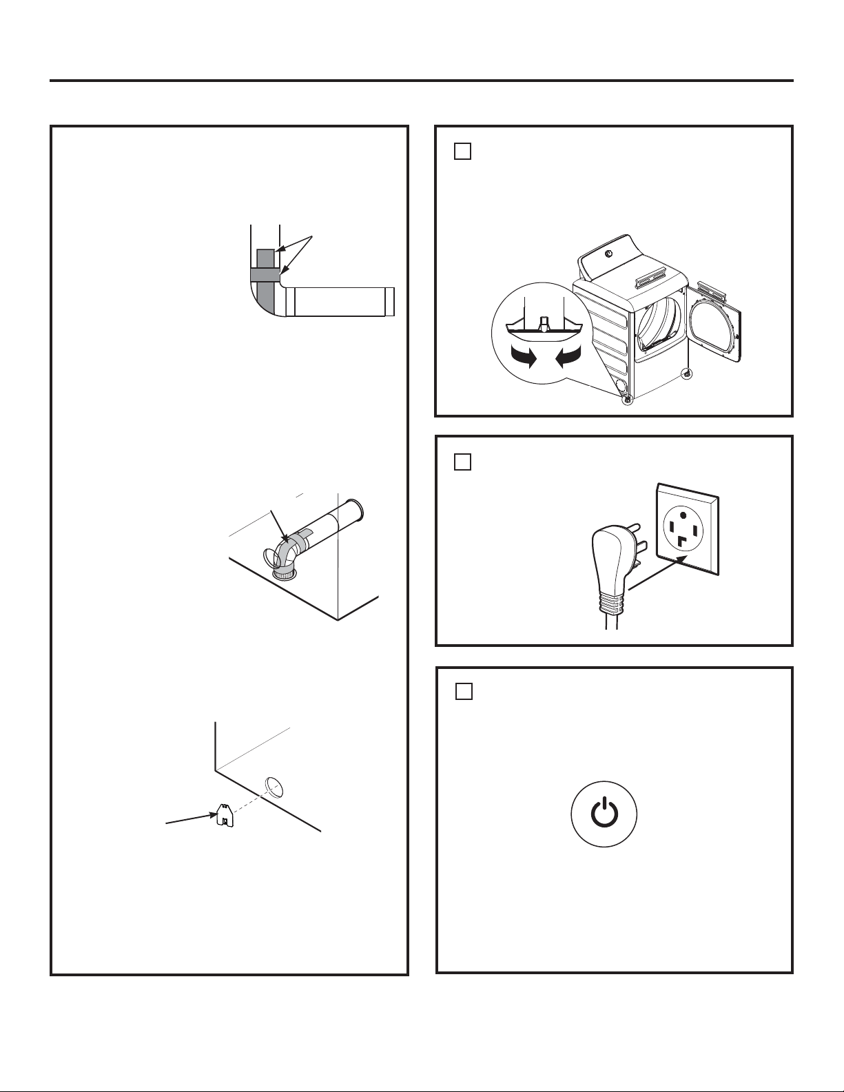
FINAL SETUP
LEVEL THE DRYER
Stand the dryer upright near the final location and
adjust the four leveling legs at the corners to ensure
that the dryer is level from side to side and front to
rear.
Lower
5DLVH
PLUG DRYER IN
1
2
DRYER START-UP
Press the Power button.
Power
NOTE: If the dryer has been exposed to
temperatures below freezing for an extended
period of time, allow it to warm up before pressing
Power. Otherwise, the display will not come on.
The dryer is now ready for use.
3
Ensure proper
ground exists
before use.
Installation Instructions
17
REVERSING THE DOOR
ABOUT REVERSING THE DOOR
IMPORTANT NOTES:
5HDGWKHLQVWUXFWLRQVDOOWKHZD\WKURXJKEHIRUH
starting.
Handle parts carefully to avoid scratching paint.
Set screws down by their related parts to avoid
using them in the wrong places.
Provide a non-scratch work surface for the door.
Normal completion time to reverse the door
VZLQJLV²PLQXWHV
IMPORTANT:
Once you begin, do not move the cabinet until door
swing reversal is completed. These instructions are
for changing the hinges from the right side to the left
side - if you ever want to switch them back to the
right side, follow these same instructions and reverse
all references to the left and right.
Tools needed:
Standard #2 Phillips screwdriver
Tape-tipped putty knife
Small flat blade screwdriver
Before you start
Unplug the dryer from its
electrical outlet
Choose the REVERSING THE DOOR instructions
A
or
B
for your model.
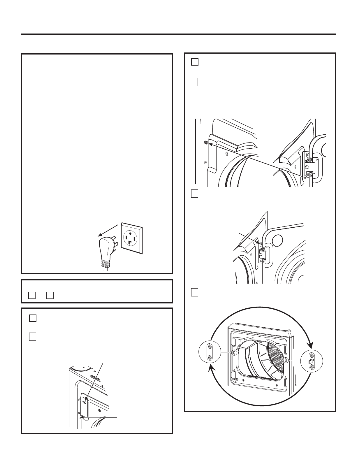
A
REVERSING THE DOOR - SOLID DOOR
MODELS
1
Open the door approximately 130 degrees. With a
putty knife, remove the 4 plastic caps located along
the left side of the front panel and set them aside.
2
5HPRYHWKHERWWRPVFUHZIURPHDFKKLQJHULJKW
side) and partially insert them into each top hinge
hole on the left side.
NOTE: All 4 front panel hinge screws will now be in
the top hinge holes - 2 on the left and 2 on the right.
3
Loosen each top hinge screw on right side5HPRYH
the door and place it on a protective flat surface to
avoid any damage.
4
5HPRYHERWKWKHEOLQGSODWHDQGWKHVWULNHSODWHDQG
install them in opposite positions.
A
REVERSING THE DOOR - SOLID DOOR
MODELS (cont.)
Plastic Cap (4)
Left side of
front panel
Blind
plate
Strike
plate
Loosen each top
hinge screw on
right side
Installation Instructions
18
A
REVERSING THE DOOR - SOLID DOOR
MODELS (cont.)
5
Mount the door on the 2 upper left side hinge screws
installed in step 2. Move the hinge screws loosened in
step 3 into the lower left side screw holes and firmly
tighten all 4 screws.
6
Install the 4 plastic caps removed in step 1 into the 4
right side front panel holes.
NOTE: To return the door to the original setup, follow
these instructions, swapping “left” and “right”.
When you finish
Plug the dryer back into
its electrical outlet.
Door
Hang door and
tighten screws
Plastic Cap (4)
5LJKWVLGHRI
front panel
REVERSING THE DOOR (cont.)
Installation Instructions
19
REVERSING THE DOOR
B
REVERSING THE DOOR - GLASS PANEL
DOOR MODELS
1
Open the door approximately 130 degrees. With a
putty knife, remove the 4 plastic caps located along
the left side of the front panel and set them aside.
2
5HPRYHWKHERWWRPVFUHZIURPHDFKKLQJHULJKW
side) and partially insert them into each top hinge
hole on the left side.
NOTE: All 4 front panel hinge screws will now be in
the top hinge holes - 2 on the left and 2 on the right.
3
Loosen each top hinge screw on right side5HPRYH
the door and place it on a protective flat surface to
avoid any damage.
Plastic Cap (4)
Left side of
front panel
Loosen each top
hinge screw on
right side
B
REVERSING THE DOOR - GLASS PANEL
DOOR MODELS (cont.)
4
5HPRYHERWKWKHEOLQGSODWHDQGWKHVWULNHSODWHDQG
install them in the opposite positions.
5
5HPRYHWKHGRRUKLQJHVFUHZVLQVLGHVFUHZVDQG
2 pocket screws. Lift the inner door upwards using a
flat blade screwdriver.
Blind
plate
Strike
plate
Inner door
Outer door
Inside
screws
Inside
screws
Pocket screws
Inside
screw
Door
hinge
screws
Installation Instructions
20
B
REVERSING THE DOOR - GLASS PANEL
DOOR MODELS (cont.)
8
Mount the assembled door on the 2 upper left side
hinge screws installed in step 2. Move the hinge
screws loosened in step 2 into the lower left side
screw holes and firmly tighten all 4 screws.
9
Install the 4 plastic caps removed in step 1 into the 4
right side front panel holes.
NOTE: To return the door to the original setup, follow
these instructions, swapping “left” and “right”.
When you finish
Plug the dryer back into
its electrical outlet.
Door
Hang door and
tighten screws
B
REVERSING THE DOOR - GLASS PANEL
DOOR MODELS (cont.)
6
5HPRYHDQGVZDSWKHSODVWLFFDSVDQGWKH
hinges.
7
5RWDWHWKHRXWHUGRRUGHJUHHVPRXQWWKHLQQHU
door back into the outer door frame and secure with
the screws removed in step 5. Make sure you mount
the hinges on the side opposite the pocket.
Install hinges from
oposite side
here
Install plastic caps
from oposite side
here
Plastic
caps
Hinges
Inner door
Inner door
Outer door
5RWDWHRXWHU
door 180°
Inside
screw
Inside
screws
Pocket screws
Inside
screw
Door
hinge
screws
Inside screw
Inside
screw
Plastic Cap (4)
5LJKWVLGHRI
front panel
REVERSING THE DOOR (cont.)
Lea estas instrucciones por completo y con
detenimiento.
IMPORTANTE – Guarde estas instrucciones
para el uso de inspectores eléctricos locales.
IMPORTANTE – Cumpla con todos los
códigos y ordenanzas vigentes.
Instale la secadora de acuerdo con las instrucciones
del fabricante y los códigos locales.
1RWDDOLQVWDODGRU² Asegúrese de dejar estas
instrucciones con el consumidor.
1RWDDOXVXDULR² Conserve estas instrucciones para
referencia futura.
La instalación de la secadora debe efectuarla un
instalador calificado.
Esta secadora debe tener una salida al exterior.
Antes de que la secadora antigua sea retirada del
servicio o eliminada, quítele la puerta.
La información sobre reparaciones y el diagrama del
cableado se encuentran en la consola de control.
No permita que niños se suban o se metan dentro
del artefacto. Se requiere una supervisión estricta
cuando el aparato es utilizado cerca de niños.
El instalador tiene la responsabilidad de efectuar una
instalación adecuada.
La garantía no cubre las fallas del producto debido a
una instalación incorrecta. .
,QVWDOHODVHFDGRUDHQOXJDUHVGRQGHODWHPSHUDWXUD
sea mayor a 50°F para un funcionamiento
satisfactorio del sistema de control de la secadora.
4XLWH\GHVFDUWHHOFRQGXFWRH[LVWHQWHGHSOiVWLFR
o de papel de aluminio y coloque un conducto
aprobado por UL.
Instrucciones
Secadora
instalación
01
Si tiene alguna pregunta, llame a 800.GE.CARES (800.432.2737) o visite nuestro sitio Web en: GEAppliances.com
ADVERTENCIA
- Riesgo de incendio
La instalación de la secadora debe efectuarla un
instalador calificado.
Instale la secadora de ropa de acuerdo con estas
instrucciones y en cumplimiento con los códigos
locales
NO instale una secadora de ropa con conductos
GHSOiVWLFRIOH[LEOH6LVHLQVWDODXQFRQGXFWR
flexible de metal (semi rígido o de tipo papel de
aluminio), debe estar aprobado por UL e instalarse
de acuerdo con las instrucciones de “Cómo
conectar la secadora a la ventilación doméstica”
de este manual. Los materiales de los conductos
flexibles a menudo se desploman, se aplastan y
atrapan pelusas. Estas condiciones obstruyen la
corriente de aire de la secadora e incrementan el
riesgo de incendio.
NO instale o almacene este aparato en un
lugar donde se vea expuesto al agua o a las
inclemencias del tiempo.
Para reducir el riesgo de una lesión grave o de
muerte, cumpla con todas las instrucciones de
instalación.
Guarde estas instrucciones. (Instaladores:
Asegúrense de dejar estas instrucciones al
consumidor).
ANTES DE COMENZAR
Éste es el símbolo de alerta de seguridad. El mismo alerta sobre potenciales riesgos que le pueden producir la muerte
ROHVLRQHVWDQWRDXVWHGFRPRDRWUDVSHUVRQDV7RGRVORVPHQVDMHVGHVHJXULGDGHVWDUiQDFRQWLQXDFLyQGHOVtPEROR
de alerta de seguridad y con la palabra “PELIGRO”, “ADVERTENCIA” o “PRECAUCIÓN”. Estas palabras se definen como:
Indica una situación de riesgo que, si no se evita, producirá la muerte o lesiones graves.
Indica una situación de riesgo que, si no se evita, podría producir la muerte o lesiones graves.
Indica una situación de riesgo que, si no se evita, podría resultar en lesiones menores o moderadas.
PELIGRO
ADVERTENCIA
PRECAUCIÓN
Impreso en México
31-16767 04-15 GE
234D2318P001
2
Instrucciones de instalación
CÓMO DESEMPACAR LA SECADORA
MANGUERA DE VAPOR Y AGUA:
*(UHFRPLHQGDHQIiWLFDPHQWHHOXVRGHSLH]DVHVSHFtILFDV
GHIiEULFD$FRQWLQXDFLyQILJXUDXQDOLVWDGHPDQJXHUDV
GHIDEULFDVTXHSRGUiDGTXLULU'LFKDVPDQJXHUDVVRQ
fabricadas y probadas de modo que se cubran las
especificaciones de GE.
*(UHFRPLHQGDHQIiWLFDPHQWHHOXVRGHQXHYDVPDQJXHUDV
de suministro de agua. Con el paso del tiempo, las mangueras
se degradas y deben ser reemplazadas cada 5 años, a fin de
reducir el riesgo de fallas sobre las mismas y daños con el agua.
Piezas y Accesorios
2UGHQHKR\DWUDYpVGH,QWHUQHWHQGEAppliancesparts.com,
ODVKRUDVGHOGtDRHQIRUPDWHOHIyQLFDOODPDQGRDO
800.626.2002GXUDQWHHOKRUDULRFRPHUFLDOKDELWXDO
Número de Pieza Accesorio
WE25X20060 Kit completo (mangueras, lavadora con
adaptador en Y) (incluido)
O
WE1M847 Manguera larga y
WE01X22395 Manguera corta
PM14X10056 Cepillo de ventilación de la abertura de la
puerta de la secadora (no incluido)
WX14X10007 Cepillo con tubería giratoria LintEater™ (no
incluido)
DIMENSIONES
APROXIMADAS
Advertencias de la Proposición 65 del Estado de California:
La Ley sobre Agua Potable Inocua y Tratamiento de Residuos Tóxicos de California (California Safe Drinking Water and
Toxic Enforcement Act) solicita al Gobernador de California que publique una lista de sustancias que el estado reconoce
TXHSURGXFHQFiQFHUGHIHFWRVGHQDFLPLHQWRXRWURVGDxRVUHSURGXFWLYRV\VROLFLWDDODVHPSUHVDVTXHDGYLHUWDQVREUHOD
posible exposición a tales sustancias.
(VWHSURGXFWRFRQWLHQHXQRRPiVTXtPLFRVTXHHO(VWDGRGH&DOLIRUQLDHQWLHQGHTXHSURGXFHQFiQFHU
defectos en el nacimiento u otros daños reproductivos.
Los electrodomésticos a gas puedan causar una exposición de bajo nivel a algunas de estas sustancias, incluyendo
EHQFHQRPRQy[LGRGHFDUERQRIRUPDOGHKLGR\KROOtQRFDVLRQDGRSULQFLSDOPHQWHSRUODFRPEXVWLyQLQFRPSOHWDGH
gas natural o combustibles de LP. La exposición a estas sustancias puede ser minimizada ventilando correctamente la
VHFDGRUDKDFLDHOH[WHULRU
ADVERTENCIA
Incline la secadora de costado y saque los paños de
HVSXPDGHHPEDODMHWLUDQGRGHORVFRVWDGRV\TXLWiQGRORV
de las patas de la secadora. Asegúrese de quitar todas las
piezas de espuma de las patas.
Saque la literatura y la bolsa que contiene la información.
4 5/8”
(11,7 cm)
Y
X
27”
(68,8 cm)
X
4 1/4”
(10,8 cm)
Visión frontal
Visión lateral
Pie
Cúbico
XY
6.0
43 3/8”
(110 cm)
26 3/4”
(68 cm)
7.0
43 3/8”
(110 cm)
29 1/2”
(75 cm)
7.3
43 3/4”
(111 cm)
30 1/2”
(78 cm)
ESPACIO LIBRE MÍNIMO EN OTROS
ESPACIOS QUE NO SEAN INSTALACIONES
EN NICHOS O ARMARIOS
3
Instrucciones de instalación
REQUERIMIENTOS PARA INSTALACIÓN
EN NICHOS O ARMARIOS
INSTALACIÓN EN CASAS MÓVILES
O PREFABRICADAS
- Riesgo de
explosión
ADVERTENCIA
Mantenga cualquier material y vapores inflamables,
tales como gasolina, alejados de la secadora.
Coloque la secadora a por lo menos 18” (46 cm.) del
piso cuando sea instalada en un garaje.
6LQRVHFXPSOHFRQHVWRVHSRGUiSURGXFLUXQD
explosión, incendio o la muerte.
,QVWDODFLyQGHEHFXPSOLUFRQOD1250$
SOBRE CONSTRUCCIÓN Y SEGURIDAD DE CASAS
PREFABRICADAS, TÍTULO 24, PARTE 32-80 o
1RUPD&$1&6$=0+RFXDQGRGLFKD
norma no sea aplicable, con la NORMA NACIONAL
ESTADOUNIDENSE PARA CASAS MÓVILES, ANSI/
NFPA Nº 501B.
/DVHFDGRUD'(%(WHQHUYHQWLODFLyQDOH[WHULRULa
YHQWLODFLyQGHOHVFDSHGHEHUiHVWDUDMXVWDGRGH
forma segura a una parte no combustible de la
casa rodante.
/DYHQWLODFLyQ12'(%(WHUPLQDUGHEDMRGHXQD
casa móvil o prefabricada.
(OPDWHULDOGHOFRQGXFWRGHYHQWLODFLyQ'(%(6(50(7$/
DEBE utilizarse el KIT 14-D346-33 para conectar
bien la secadora a la estructura.
/DYHQWLODFLyQ12'(%(FRQHFWDUVHDQLQJ~QRWUR
FRQGXFWRYHQWLODFLyQRFKLPHQHD
1RXWLOLFHWRUQLOORVSDUDSODFDVGHPHWDOXRWURV
dispositivos de sujeción que se extiendan
al interior de la ventilación de salida.
Debe contar con una abertura con un espacio libre de
por lo menos 25 pulgadas cuadradas para el ingreso
GHDLUHH[WHULRUGHQWURGHODVHFDGRUDKDELWDFLyQ
3DUDDFFHGHUDLQIRUPDFLyQVREUHODFRQH[LyQ
eléctrica, consulte la section.
Si se aprobó la instalación de su secadora en
DOFREDRDUPDULRHVWRILJXUDUiHQXQDHWLTXHWD
en el reverso de la secadora.
Esta secadora DEBE tener una ventilación
al exterior. Ver la sección SALIDA AL EXTERIOR
DE LA SECADORA.
El espacio libre mínimo entre la secadora y las
paredes adyacentes u otras superficies es:
0” en ambos lados
3” (7.62 cm) en el frente
0” en la parte trasera pero 1” (2.54 cm)
mínimo es la recomendada
(O HVSDFLR YHUWLFDO PtQLPR GH OD SDUWH VXSHULRU GH OD
VHFDGRUDKDVWDORVHVWDQWHVDUPDULRVWHFKRVHWFHVGH
6HGHEHUiFRQVLGHUDUTXHVHGHEHEULQGDUHOGHVSHMH
adecuado para la instalación y el servicio técnico.
Las puertas del armario deben contar con rejillas
u otro tipo de ventilación y tener por lo menos
60 pulgadas cuadradas de espacio abierto
igualmente distribuido. Si el armario incluye una
lavadora y una secadora, las puertas deben
contener un mínimo de 120 pulgadas cuadradas
de espacio abierto distribuido uniformemente.
NOTA: CUANDO EL CONDUCTO DE ESCAPE SE
ENCUENTRA EN LA PARTE TRASERA DE LA SECADORA,
LA CONFIGURACIÓN DEL DUCTO DE ESCAPE PUEDE
5(48(5,50$6'(µ'((63$&,2(1/$3$57(
TRASERA. 1” (2.54 CM) MÍNIMO ES LA RECOMENDADA.
Secadoras a Gas Únicamente:
1RVHGHEHUiLQVWDODUQLQJ~QRWURHOHFWURGRPpVWLFR
que consuma combustible en el mismo armario
GRQGHKD\DXQDVHFDGRUDDJDV
/DVHFDGRUDVHGHEHUiGHVFRQHFWDUGHODWXEHUtD
de suministro de gas durante la prueba de presión
en presiones superiores a ½ psi (3.5 kPa).
CABLES DE CORRIENTE:
*(UHFRPLHQGDHQIiWLFDPHQWHHOXVRGHSLH]DVHVSHFtILFDVGH
IiEULFD6HOHFFLRQHHOFDEOHGHFRUULHQWHTXHVHDGHF~HDVXV
requisitos de instalación.
Ordene a través de Internet en GEAppliancesParts.com, las 24
KRUDVGHOGtDRHQIRUPDWHOHIyQLFDOODPDQGRDO800.626.2002,
GXUDQWHHOKRUDULRFRPHUFLDOKDELWXDO
Pieza Nº Tipo Longitud Amperios
WX9X2 3-Clavijas 4 Pies 30
WX9X3 3-Clavijas 5 Pies 30
WX9X4 3-Clavijas 6 Pies 30
WX9X18 4-Clavijas 4 Pies 30
WX9X19 4-Clavijas 5 Pies 30
WX9X20 4-Clavijas 6 Pies 30
Los espacios libres mínimos respecto de superficies
combustibles y de aberturas de aire son: 0” a ambos
lados; 1” (2.54 cm) en el frente; 0” en la parte trasera
pero 1” (2.54 cm) mínimo es la recomendada. Debe
tenerse en cuenta un espacio libre adecuado para
un funcionamiento y reparación correctos.
Secadoras a Gas Únicamente - continuado:
8QDURVFDFXELHUWD137GHµDFFHVLEOHSDUD
la conexión de un dispositivo de calibración,
GHEHUiVHULQVWDODGDLQPHGLDWDPHQWHDUULEDGHOD
conexión del suministro de gas a la secadora.
Para producir vapor, la secadora debe conectarse
al suministro de agua fría. Ya que la lavadora
también debe conectarse al agua fría, debe
introducirse un conector en “Y” para permitir que
ambas mangueras de entrada puedan utilizarse al
mismo tiempo.
NOTA: Utilice las nuevas mangueras de entrada
provistas; nunca utilice mangueras viejas.
1&LHUUHHO JULIR GH DJXD IUtD4XLWHOD PDQJXHUD
de entrada de la lavadora del conector de la
YiOYXODGHOOHQDGRIUtD
2. Asegúrese de que la arandela plana de goma
se encuentre en su lugar y sujete una unión
KHPEUD GH OD PDQJXHUD FRUWD HQ HO FRQHFWRU
GHODYiOYXODGHOOHQDGRGHODODYDGRUD$MXVWHD
PDQRKDVWDTXHHVWpILUPHPHQWHDVHQWDGD
3. 6XMHWH XQ H[WUHPR PDFKR GHO FRQHFWRU HQ
´<µ D OD XQLyQ KHPEUD GH OD PDQJXHUD FRUWD
Asegúrese de que la arandela plana de goma se
HQFXHQWUHHQVXOXJDU$MXVWHDPDQRKDVWDTXH
esté firmemente asentada.
4. Introduzca el filtro en la unión de la manguera
de entrada de la lavadora. Si la arandela plana
de goma ya se encuentra en su lugar, quítela
antes de instalar el filtro. Sujete esta unión a
XQ H[WUHPR PDFKR GHO FRQHFWRU HQ ´<µ $MXVWH
DPDQRKDVWDTXHHVWpILUPHPHQWHDVHQWDGD
5. Asegúrese de que la arandela plana de goma
se encuentre en su lugar y sujete la manguera
larga de entrada de la secadora a un extremo
PDFKRGHOFRQHFWRUHQ´<µ$MXVWHDPDQRKDVWD
que esté firmemente asentada.
6. Asegúrese de que la arandela plana de goma se
encuentre en su lugar y sujete el otro extremo
de la manguera larga de entrada al conector
GHODYiOYXODGHOOHQDGRHQODSDUWHLQIHULRUGHO
panel trasero de la secadora. Ajuste a mano
KDVWDTXHHVWpILUPHPHQWHDVHQWDGD
4
Instrucciones de instalación
CÓMO CONECTAR MANGUERAS DE ENTRADA
CÓMO CONECTAR MANGUERAS
DE ENTRADA
CÓMO CONECTAR MANGUERAS
DE ENTRADA (cont.)
7. Utilizando alicates, ajuste todas las uniones con
un giro adicional de dos tercios.
NOTA:1RDMXVWHGHPiV3XHGHQGDxDUVHODV
uniones.
8. Abra el grifo de agua.
9. Controle la presencia de pérdidas alrededor
del conector en “Y”, el grifo y las uniones
de las mangueras.
REQUISITOS DE SUMINISTRO DE AGUA
Los grifos de agua caliente y fría DEBEN instalarse
dentro de las 42 pulg. (107 cm) de la entrada de
agua de la lavadora. Los grifos DEBEN ser del tipo
de manguera de jardín de 3/4 pulg. (1.9 cm) para
que las mangueras de entrada puedan conectarse.
/DSUHVLyQGHDJXD'(%(KDOODUVHHQWUH\
libras por pulgada cuadrada. La compañía de agua
puede informarle sobre la presión de agua.
NOTA: Se recomienda el uso de un suavizante de
agua para reducir la acumulación de sarro dentro
del generador de vapor si el suministro doméstico
contiene agua muy dura.
Instrucciones de instalación
5
CÓMO CONECTAR UNA SECADORA A GAS
(si se cuenta con una secadora eléctrica, saltear este paso)
Antes de comenzar la instalación, apague
el disyuntor o quite los fusibles de la secadora
de la caja eléctrica. Verifique que el cable
GHODVHFDGRUDHVWpGHVHQFKXIDGR
del tomacorriente.
*LUHDODSRVLFLyQ2))DSDJDGRODYiOYXODGHJDV
de la secadora de la línea de suministro.
Desconecte y elimine el conector flexible de gas
y el material del conducto.
9iOYXOD
de cierre
HERRAMIENTAS NECESARIAS
MATERIALES NECESARIOS
Llaves ajustables
de 10” (2)
Llave para tubos de
8”
Destornillador
de lados planos
Nivel
Pinzas
Codo de metal de
4”GLiPHWUR
Compuesto o PTFE
cinta para tuberías
Conector de tubería
de gas flexible
Abrazaderas de tubería
(2) o abrazaderas de
resorte (2)
Gafas de seguridad
Conducto de metal de 4”
GLiPHWURUHFRPHQGDGR
4” Placa de cubierta
(Kit WE1M454)
Conducto de metal
flexible de 4”
GLiPHWURVLIXHVH
necesario)
Guantes
Solución jabonosa
para detección de
pérdidas
Campana de salida
Cinta aislante
Gas adaptador (2),
codo, y tapón de
tubería
6
Instrucciones de instalación
CÓMO CONECTAR UNA SECADORA A GAS (cont.)
(si se cuenta con una secadora eléctrica, saltear este paso)
REQUERIMIENTOS DE GAS
CONEXIÓN DE SUMINISTRO DE GAS
DE LA SECADORA
SUMINISTRO DE GAS
Debe instalarse una toma a rosca de 1/8” NPT,
accesible para una conexión del manómetro de
prueba, inmediatamente en sentido ascendente
GHODFRQH[LyQGHVXPLQLVWURGHJDVKDFLD
la secadora. Si tiene dudas sobre la instalación
de la toma, comuníquese con su empresa
proveedora de gas local.
La línea de suministro debe ser de tubería rígida
de 1/2” y debe contar con un cierre accesible
dentro de los 6 pies de la secadora, dentro de la
PLVPDKDELWDFLyQGRQGHVHHQFXHQWUDODPLVPD
Utilice compuesto para rosca de tubería apropiado
para gas natural o LP o utilice cinta de PTFE.
Una el conector de metal flexible a la secadora
y al suministro de gas.
/DLQVWDODFLyQGHEHUiVHUFRQIRUPHFRQORVFyGLJRV
locales, o en ausencia de los códigos locales, con
el Código Nacional de Gas Combustible (National
Fuel Gas Code), ANSI Z223.1/NFPA 54, o el Código de
Instalación de Gas Natural o Propano (Natural Gas
and Propane Installation Code), CSA B149.1.
EN LA MANCOMUNIDAD DE
MASSACHUSETTS
Este producto debe instalarlo un plomero
matriculado o un instalador de gas.
&XDQGRXVHYiOYXODVHVIpULFDVGHDSDJDGR
GHJDVGHEHUiQVHUGHOWLSRGHPDQLMDHQ7
Si se usa una conexión flexible para gas, ésta
no debe superar los 3 pies.
AJUSTE PARA ELEVACIÓN
Los niveles de entrada de las secadoras de ropa
DJDVHVWiQEDVDGRVHQHOIXQFLRQDPLHQWRDOQLYHO
de mar y no necesitan ajustes para funcionar
en o por debajo de los 2000 pies de elevación.
3DUDXQIXQFLRQDPLHQWRDPiVGHSLHVGH
elevación, los niveles de entrada se deberían
reducir a un promedio del 4 por ciento por cada
1000 pies sobre el nivel del mar.
La instalación debe cumplir con los códigos
y ordenanzas locales, o en su ausencia, con
el CÓDIGO NACIONAL DE GAS COMBUSTIBLE
(NATIONAL FUEL GAS CODE), ANSI Z223.
- Riesgo de
explosión
ADVERTENCIA
Use una línea nueva de suministro de gas flexible
que esté aprobada por CSA International. Nunca
vuelva a usar conectores flexibles viejos.
,QVWDOHODYiOYXODGHFLHUUH
'HIRUPDVHJXUDDMXVWHWRGDVODVFRQH[LRQHVGH
gas.
Si la conexión fue realizada a gas LP, solicite a
una persona calificada que le asegure que la
presión del gas no supera una columna de agua
de 13”.
Ejemplos de una persona calificada incluyen:
Personal de calefacción calificado, personal
autorizado de una compañía de gas, y personal
autorizado del servicio técnico.
6LQRVHFXPSOHFRQHVWRVHSRGUiSURGXFLUOD
muerte, una explosión o incendio.
1-7/8"
3-1/8"
NOTA: Agregue a la dimensión vertical la distancia
entre la parte inferior del gabinete y el piso.
SUMINISTRO DE GAS ROSCA MACHO NPT DE 3/8"
'HEHXWLOL]DUXQFRQHFWRUIOH[LEOHPHWiOLFR
listado por ANSI Z21.24/CSA 6.10. La longitud del
FRQHFWRUQRH[FHGHUiSLHV
(VWDVHFDGRUDDJDVHVWiHTXLSDGDFRQXQ
PRQWDMHGHYiOYXOD\TXHPDGRUSDUDXWLOL]DUVyOR
con gas natural. Mediante el kit de conversión
WE25X217, la organización de atención local
puede convertir esta secadora para su uso con
gas propano (LP).
(Para convertir de gas propano
/3DOJDVQDWXUDOVHXWLOL]DUiHONLWGHFRQYHUVLyQ
WE25X218.)
TODAS LAS CONVERSIONES DEBEN
LLEVARLAS A CABO PERSONAL CAPACITADO Y
CALIFICADO EN CUMPLIMIENTO CON CÓDIGOS
/2&$/(6<5(48(5,0,(1726'(25'(1$1=$6
Instrucciones de instalación
7
Instale una toma a rosca de 1/8” NPT
HQODYiOYXODGHDSDJDGRGHODWXEHUtDGHJDV
de la secadora para controlar la presión
de gas en la entrada.
Instale un adaptador de unión cónica
en la toma a rosca.
NOTA: Aplique compuesto para tubería o cinta
PTFE a las roscas del adaptador y a la toma.
Una el conector de tubería de gas de metal
flexible al adaptador.
B
Ajuste la conexión de tubería flexible de gas,
utilizando dos llaves ajustables.
C
D
Ajuste todas las conexiones mediante
dos llaves ajustables. No ajuste de más.
E
CÓMO CONECTAR LA SECADORA
AL SUMINISTRO DE GAS (cont.)
&LHUUHODYiOYXODGHDSDJDGRGHOJDV
F
Aplique compuesto para
tubería o cinta PTFE en
WRGDVODVURVFDVPDFKR
9iOYXODGHDSDJDGR
Toma a
rosca
CÓMO CONECTAR LA SECADORA
AL SUMINISTRO DE GAS
,QVWDOHXQFRGRKHPEUD137GHµDOILQDO
de la entrada de gas de la secadora.
Instale un adaptador de unión cónica
GHµDOFRGRKHPEUD
IMPORTANTE: Utilice una llave para tubos para
sostener bien el extremo de la entrada de gas
de la secadora para no doblar la entrada.
NOTA: Aplique compuesto para tubería o cinta
PTFE a las roscas del adaptador y la entrada de
gas de la secadora.
A
Aplique compuesto para tubería al
adaptador y a la entrada de gas de la
secadora.
Codo
Adaptador
Los productos que no suministrados
Adaptador
Tapón de tubería
npt de 1/8”
para controlar
la presión de
entrada de gas
9iOYXODGHFLHUUH
Tamaño de
tubería al
menos 1/2”
NPT de 3/8”
Conector
nuevo de
línea de gas
de metal
flexible
8
Instrucciones de instalación
CÓMO CONECTAR UNA SECADORA A GAS (cont.)
(si se cuenta con una secadora eléctrica, saltear este paso)
PRUEBA DE PÉRDIDAS
Abra la
YiOYXOD
de gas
CONEXIÓN ELÉCTRICA INFORMACIÓN
SOBRE LAS SECADORAS A GAS (cont.)
La secadora debe contar con una conexión
eléctrica a tierra en cumplimiento con los códigos
locales, o si éstos no existieran, de acuerdo con
el Código Eléctrico Nacional, ANSI/NFPA 70 o el
Código Eléctrico Canadiense CSA C22.1.
Este artefacto debe contar con un suministro de
120V, 60Hz, debe estar conectado a un circuito
derivado individual con una adecuada conexión
a tierra y deben contar con la protección de un
disyuntor o fusible de tiempo retardado de 15 o
20 amperios. Si el suministro eléctrico provisto no
reúne estos requerimientos, es responsabilidad
del dueño solicitar a un electricista calificado la
instalación de un tomacorriente de 3 patas con
conexión a tierra.
9HULILTXHTXHKD\D
una conexión a tierra
adecuada antes del uso.
Nunca utilice una llama abierta para detectar
pérdidas de gas.
Controle todas las conexiones con una solución
jabonosa o un elemento equivalente.
Aplique una solución jabonosa. La solución para
controlar pérdidas no debe contener amoníaco,
ya que este producto puede dañar los accesorios
de bronce.
6LVHGHWHFWDQSpUGLGDVFLHUUHODYiOYXODYXHOYD
a ajustar la junta y repita la prueba de la solución
MDERQRVDDQGUHSHDWWKHVRDSWHVW
6LORVFyGLJRVORFDOHVORSHUPLWHQVHSRGUiDJUHJDU
un cable a tierra externo (no provisto), ajustando el
mismo al tornillo conectado a tierra de color verde
en la parte trasera de la secadora, y a una conexión
FDxHUtDPHWiOLFDGHDJXDIUtDFRQHFWDGDDWLHUUDX
otra conexión a tierra establecida.
CONEXIÓN ELÉCTRICA INFORMACIÓN
SOBRE LAS SECADORAS A GAS
- Riesgo de Descarga Eléctrica
ADVERTENCIA
(QFKXIHHQXQWRPDFRUULHQWHFRQFRQH[LyQDWLHUUD
de 3 cables.
NO retire la conexión a tierra.
NO UTILICE un cable de extensión.
NO UTILICE XQHQFKXIHDGDSWDGRUFRQHVWH
artefacto.
6LQRVHVLJXHQHVWDVLQVWUXFFLRQHVVHSRGUi
producir la muerte o descargas eléctricas.
Tornillo de
conexión
a tierra
Codo de metal de
µGHGLiPHWUR
Alivio de tensión de
3/4” (reconocido por
UL)
Abrazaderas de
tubería de 4” (2)
o abrazaderas de
resorte de 4” (2)
Gafas de seguridad
Conducto de metal
GHµGHGLiPHWUR
(recomendado)
Conducto de metal
flexible de 4”
GHGLiPHWUR
(si fuese necesario)
Guantes
Campana de salida
Cinta aislante
Kit de cable de
energía de la
secadora (no incluido
con la secadora)
Clasificado UL, de
120/240V, 30A con
3 o 4 patas. Identifique
HOWLSRGHHQFKXIH
según el tomacorriente
de la vivienda antes de
comprar el cable.
4” Placa de cubierta
(Kit WE1M454)
CÓMO CONECTAR UNA SECADORA ELECTRICA
(Sáltese si se trata de las secadoras a gas o si su secadora ya tiene un cable de alimentación conectado)
Instrucciones de instalación
9
Antes de efectuar la conexión eléctrica, desactive
los disyuntores o quite los fusibles del circuito
de la secadora de la caja eléctrica. Verifique
TXHHOFDEOHGHODVHFDGRUDHVWpGHVHQFKXIDGR
del tomacorriente. NUNCA OLVIDE DE VOLVER
$&2/2&$5/$7$3$'($&&(62'(/%/248(
TERMINAL.
Pinzas
Destornillador de
lados planos
'HVWRUQLOODGRU3KLOOLSV
Nivel
MATERIALES NECESARIOS
HERRAMIENTAS NECESARIAS
10
CÓMO CONECTAR UNA SECADORA ELECTRICA (cont.)
(Sáltese si se trata de las secadoras a gas o si su secadora ya tiene un cable de alimentación conectado)
Instrucciones de instalación
CONEXIÓN ELÉCTRICA INFORMACIÓN
SOBRE LAS SECADORAS ELÉCTRICAS
ADVERTENCIA
- Riesgo de incendio
Use un cable de suministro de corriente de la secadora
de 30 amperes y 240V de la lista de UL, con terminales
de anillo cerradas o terminales de espada con
extremos al revés.
Use un amortiguador con refuerzo de la lista de UL.
Desconecte la corriente antes de realizar conexiones
eléctricas.
Conecte el cable neutro (el blanco o el cable central) a
la terminal central.
(OFDEOHDWLHUUDYHUGHRSHODGRVHGHEHUiFRQHFWDUDO
conector a tierra verde.
Conecte los dos cables de suministro restantes a las
dos terminales restantes.
De forma segura ajuste todas las conexiones eléctricas.
Reemplace la tapa del bloque terminal.
6LQRFXPSOHFRQHVWRVHSRGUiSURGXFLUODPXHUWH
incendio o descarga eléctrica.
Para realizar conexiones eléctricas con
un cable de corriente:
CONEXIÓN ELÉCTRICA INFORMACIÓN
SOBRE LAS SECADORAS ELÉCTRICAS
Para conexiones directas de cables:
ADVERTENCIA
- Riesgo de incendio
Use un cable de cobre con calibre de 10
Use un amortiguador con refuerzo de la lista de UL.
Desconecte la corriente antes de realizar conexiones
eléctricas.
Conecte el cable neutro (el blanco o el cable central) a
la terminal central.
(OFDEOHDWLHUUDYHUGHRSHODGRVHGHEHUiFRQHFWDUDO
conector a tierra verde.
Conecte los dos cables de suministro restantes a las
dos terminales restantes.
De forma segura ajuste todas las conexiones eléctricas.
Reemplace la tapa del bloque terminal.
6LQRFXPSOHFRQHVWRVHSRGUiSURGXFLUODPXHUWH
incendio o descarga eléctrica.
INSTRUCCIONES DE CONEXIÓN A TIERRA
Para una secadora conectada con cable con
conexión a tierra:(VWDVHFDGRUDGHEHUiHVWDU
conectado a tierra. En caso de mal funcionamiento
RDYHUtDODFRQH[LyQDWLHUUDUHGXFLUiHOULHVJR
de descargas eléctricas al brindar un camino con
una resistencia menor para la corriente eléctrica.
(VWDVHFDGRUDHVWiHTXLSDGDFRQXQFDEOHFRQXQ
conductor para la conexión a tierra del equipo y un
HQFKXIHFRQFRQH[LyQDWLHUUD(OHQFKXIHGHEHUi
estar conectado a un tomacorriente instalado
en forma adecuada y con conexión a tierra de
acuerdo con todos los códigos y ordenanzas
locales.
Una conexión inapropiada del
conductor de conexión a tierra
del equipo puede provocar riesgos de descargas
eléctricas. Consulte a un electricista calificado o
personal o representantes del servicio técnico si
tiene dudas de que el electrodoméstico se encuentre
conectado a tierra apropiadamente. NO modifique
HOHQFKXIHHQHOFDEOHGHVXPLQLVWURGHFRUULHQWH6L
no coincide con la toma de corriente, contrate a un
electricista calificado para que instale una toma de
corriente en forma adecuada.
GUARDE ESTAS INSTRUCCIONES
INSTRUCCIONES DE CONEXIÓN A TIERRA
Para una secadora conectada de forma
permanente: Esta secadora debe estar conectada
a un sistema de cableado de metal permanente
con conexión a tierra o se debe tender un
conductor para la conexión a tierra del equipo con
los conductores del circuito y ser conectado al
terminal de tierra del electrodoméstico.
Una conexión inapropiada del
conducto de conexión a tierra
del equipo puede provocar riesgos de descargas
eléctricas. Consulte a un electricista calificado
o personal o representantes del servicio técnico
si tiene dudas de que el electrodoméstico se
encuentre conectado a tierra apropiadamente.
GUARDE ESTAS INSTRUCCIONES
ADVERTENCIA
ADVERTENCIA
Instrucciones de instalación
11
CÓMO CONECTAR LA SECADORA
USANDO UNA CONEXIÓN DE 4 CABLES
(DEBE UTILIZARSE EN INSTALACIONES
DE CASAS RODANTES)
NOTA:
Desde el 1 de enero de 1996, el Código Eléctrico
Nacional exige que las nuevas construcciones utilicen una
conexión de 4 cables a una secadora eléctrica. También debe
usarse un cable de 4 alambres cuando los códigos locales no
permiten una conexión a tierra a través de cable neutral.
NO debe usarse una conexión de tres cables en una
construcción nueva.
CÓMO CONECTAR LA SECADORA
UTILIZANDO UNA CONEXIÓN DE 3 CABLES
1. Desactive el disyuntor (30 amperios) o quite el fusible del
circuito de la secadora de la caja eléctrica.
2. Verifique que el cable de la secadora esté
GHVHQFKXIDGRGHOWRPDFRUULHQWH
3.4XLWHODWDSDGHOFDEOHGHHQHUJtDXELFDGDHQODSDUWH
trasera inferior.
4. Instale un alivio de tensión de 3/4 pulgadas reconocido
por UL en el orificio de entrada del cable de energía.
Pase el cable de energía a través del alivio de tensión.
5. Conecte el cable de energía de la siguiente manera:
A. Conecte los dos cables vivos a los tornillos externos
del bloque terminal (marcado L1 y L2).
B. Conecte el cable neutral (blanco) al centro del
bloque terminal (marcado N).
6. Asegúrese de que la cinta de conexión a tierra esté conectada
a la terminal neutral (central) del bloque y al tornillo verde de
conexión a tierra de la parte trasera del gabinete. Ajuste por
firmemente todos los tornillos (3) del bloque terminal.
7. Ajuste bien el cable de energía al alivio de tensión.
8. Vuelva a instalar la tapa.
Conexión de 3 cables
12XVDUHQ&DQDGi
NO usar en instalaciones en casas móviles.
NO usar en casas nuevas.
12XVDUHQYHKtFXORVUHFUHDWLYRV
12XVDUHQiUHDVGRQGHORVFyGLJRVORFDOHVSURKtEHQOD
connexión eléctrica a tierra por el medio del cable neutral.
NUNCA OLVIDE DE VOLVER A COLOCAR LA TAPA
DEL BLOQUE TERMINAL.
NUNCA OLVIDE DE VOLVER A COLOCAR LA TAPA
DEL BLOQUE TERMINAL.
1. Desactive el disyuntor (30 amperios) o quite el fusible
del circuito de la secadora de la caja eléctrica.
2. Verifique que el cable de la secadora esté
GHVHQFKXIDGRGHOWRPDFRUULHQWH
3.4XLWHODWDSDGHOFDEOHGHHQHUJtDXELFDGDHQODSDUWH
trasera inferior.
4.4XLWH\GHVFDUWHODFLQWDGHFRQH[LyQDWLHUUD&RQVHUYH
el tornillo verde de conexión a tierra para el paso 7.
5. Instale un alivio de tensión de 3/4 pulgadas reconocido
por UL en el orificio de entrada del cable de energía.
Pase el cable de energía a través del alivio de tensión.
6. Conecte el cable de energía de la siguiente manera:
A. Conecte los dos cables vivos a los tornillos externos
del bloque terminal (marcado L1 y L2).
B. Conecte el cable neutral (blanco) al centro del
bloque terminal (marcado N).
7. Conecte el cable a tierra del cable de energía con el
tornillo verde de conexión a tierra (orificio sobre el
soporte de alivio de tensión). Ajuste por firmemente
todos los tornillos (3) del bloque terminal.
8. Ajuste bien el cable de energía al alivio de tensión.
9. Vuelva a instalar la tapa.
Si así lo requirieran los códigos locales, instale una conexión
a tierra externa (no provista) a metal con conexión a tierra,
tuberías de agua fría con conexión a tierra u otra conexión
a tierra establecida por un electricista calificado.
Tornillos (2)
4XLWHODFLQWDGHFRQH[LyQDWLHUUD
\GHVFiUWHOD&RQVHUYHHOWRUQLOOR
verde de conexión a tierra.
Cable
vivo
Coloque
aquí el
tornillo
verde de
conexión
a tierra
Cable
verde
Alivio de
tensión
de 3/4”
reconocido
por UL
4 conductores de cobre #10 AWG mínimo o kit de cable de
suministro de
energía de 120/240V
30A marcado para su uso con
secadoras y provisto con
terminales
GHEXFOHFHUUDGRRKHPEUDFRQ
H[WUHPRVKDFLDDUULEDQRSURYLVWRV
Fusible
Cable
vivo
Neutral
(blanco)
Soporte
de alivio
de tensión
Tapa
Tornillo
Tornillos (2)
Cable
vivo
3 conductores de cobre #10 AWG mínimo o kit de cable de suministro
de energía de 120/240V 30A marcado para su uso con secadoras
\SURYLVWRFRQWHUPLQDOHVGHEXFOHFHUUDGRRKHPEUDFRQH[WUHPRV
KDFLDDUULEDQRSURYLVWRV
Fusible
Cable
vivo
Neutral
(blanco)
Tapa
Tornillo
Tornillo verde de
conexión a tierra
Alivio de
tensión de 3/4”
reconocido
por UL
Soporte
de
alivio de
tensión
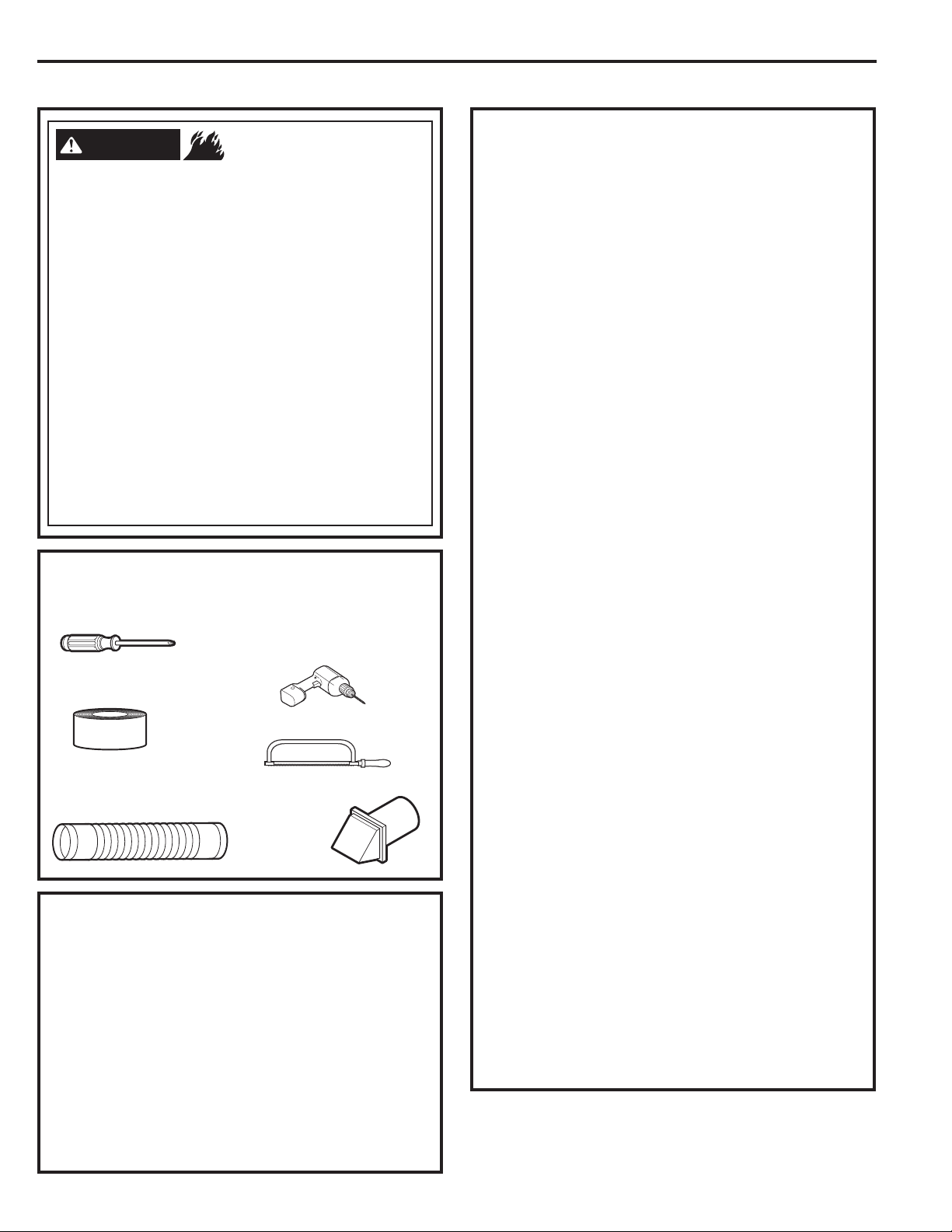
Instrucciones de instalación
12
SALIDA AL EXTERIOR DE LA SECADORA
ADVERTENCIA
- Riesgo de incendio
Esta secadora DEBE tener una ventilación
al exterior.
Utilice sólo un conducto de metal rígido de 4” para la
ventilación de salida doméstico.
Utilice
sólo un conducto de transición de metal rígido
de 4” o de la lista de UL para conectar la secadora a la
VDOLGDGHOKRJDUFRQGXFWR
NOXVHXQDYHQWLODFLyQGHOSOiVWLFR
NOXVHODVDOLGDGHXQDFKLPHQHDODVDOLGDGHOD
FRFLQDYHQWLODFLyQGHJDVSDUHGFLHORUDVRiWLFR
espacio de rastreo, o espacio escondido de una
edificación.
NO instale una pantalla en o sobre el conducto de
salida.
NOXVHXQFRQGXFWRPiVODUJRTXHDTXpOHVSHFLILFDGR
en la tabla de longitud de salida.
6LQRVHVLJXHQHVWDVLQVWUXFFLRQHVVHSRGUiSURGXFLUOD
muerte o un incendio.
CONEXIÓN DE LA SECADORA A LA
VENTILACIÓN DE LA CASA
CONDUCTO DE TRANSICIÓN DE METAL RÍGIDO
Para un mejor funcionamiento del secado, se
recomienda el uso de un conducto de transición de
metal rígido.
Los conductos de transición de metal rígido reducen el
riesgo de que se puedan aplastar o doblar.
CONDUCTO DE TRANSICIÓN DE METAL FLEXIBLE
SECADORA DE ROPA
DE LA LISTA DE UL
Si un conducto de metal rígido no puede ser
utilizado, entonces un conducto de metal flexible
aprobado por UL puede ser utilizado. (GE partes –
PM08X10085, WX08X10085 o WX08X10077.)
Nunca instale un conducto de transición en paredes,
cielos rasos, pisos u otros espacios adjuntos.
/DORQJLWXGWRWDOGHO
conducto de transición
QRGHEHUi
superar los 8’ (2.4 m).
3DUDPXFKDVDSOLFDFLRQHVVHUHFRPLHQGD
HQIiWLFDPHQWHODLQVWDODFLyQGHFRGRVWDQWRHQOD
secadora como en la pared. Los codos permiten
que la secadora pueda estar junto a la pared sin
que se aplaste ni se doble el conducto de transición,
maximizando el rendimiento del secado.
(YLWHTXHODWXEHUtDVHDSR\HVREUHREMHWRVFRUWDQWHV
CONDUCTO DE TRANSICIÓN DE METAL FLEXIBLE (TIPO
HOJA DE ALUMINIO) DE LA LISTA DE UL
En instalaciones especiales, puede ser necesario
conectar la secadora a la ventilación domestica
usando un conducto de metal flexible (tipo papel
de aluminio). Un conducto universal flexible
aprobado por UL (GE partes - PM8X73 o WX8X73)
puede ser utilizado UNICAMENTE en instalaciones
donde un conductor de metal rígido o flexible no
SXHGHVHUXWLOL]DGR\GRQGHXQGLiPHWURGHµ
puede mantenerse a lo largo del conducto.
(Q&DQDGi\HQ(VWDGRV8QLGRVVyORVHSRGUiQXVDUORV
conductos
de transición
que cumplan con “UL 2158A
STANDARD FOR CLOTHES DRYER TRANSITION DUCT”
(UL 2158A - Norma de conductos para secadoras de
ropa).
(YLWHTXHODWXEHUtDVHDSR\HVREUHREMHWRVFRUWDQWHV
3DUDXQPHMRUIXQFLRQDPLHQWR
1. Deslice un extreme del conducto sobre la tubería
de salida de la secadora de ropa.
2. Asegure el conducto con una abrazadera.
3. Con la secadora en su posición permanente,
H[WLHQGDHOFRQGXFWRKDVWDVXPi[LPDH[WHQVLyQ
Permita que 2” del conducto se superpongan con
la tubería de escape. Corte y retire el sobrante del
FRQGXFWR0DQWHQJDHOFRQGXFWRORPiVUHFWR
SRVLEOHSDUDORJUDUHOIOXMRGHDLUHPi[LPR
4. Asegure el conducto a la tubería de escape con
la otra abrazadera.
HERRAMIENTAS Y MATERIALES NECESARIOS
PARA INSTALAR UN CONDUCTO DE SALIDA
PIEZAS DISPONIBLES EN LAS
ORGANIZACIONES DE SERVICIO LOCALES
&RPSRQHQWHVFRQGXFWRVPHWiOLFRVUtJLGRV
WX8X63 4 x 1 Ducto
WX8X64 4 x 2 Ducto
WX8X51 4 Codo
WX8X59 &DSXFKyQGH$OXPLQLR
&RPSRQHQWHVFRQGXFWRVPHWiOLFRVIOH[LEOHV
WX8X58 Pinzas 4 (2)
WX8X59 &DSXFKyQGH$OXPLQLR
WX08X10077
6 Ducto UL-, Metal Flexible (Semi-
Rígido) 2 Pinzas, 2 Codos de cierre
WE1M454
Cubierta para abertura del escape posterior
'HVWRUQLOODGRUSKLOOLSV
Cinta aislante o
abrazaderas de tubería
Conducto de metal de
4” (10,2 cm) flexible o
rígido listado UL
Perfore con una broca
de 1/8” drill bit (para
ventilación inferior)
Sierra para metales
Campana de
ventilación
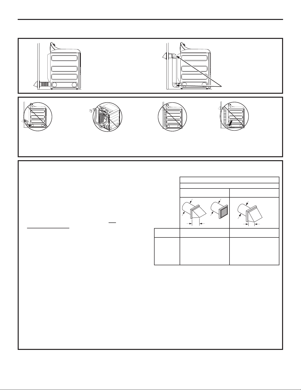
Instrucciones de instalación
Al utilizar una salida de mayor longitud a la
especificada se:
,QFUHPHQWDUiQORVWLHPSRVGHVHFDGR\HOFRVWR
de energía.
5HGXFLUiODYLGD~WLOGHODVHFDGRUD
$FXPXODUiSHOXVDORTXHSRGUtDJHQHUDUXQ
riesgo potencial de incendio.
La correcta instalación de salida es SU
RESPONSABILIDAD.
Los problemas generados por una instalación
incorrecta no se encuentran cubiertos por
la garantía.
13
La longitud MÁXIMA PERMITIDA del sistema de salida
depende del tipo de conducto, la cantidad de curvas, la
clase de campana de salida (cubierta de pared) y todas
ODVFRQGLFLRQHVLQGLFDGDVHQHOJUiILFR
Codos internos agregados para conversiones de
YHQWLODFLyQODWHUDORLQIHULRUVHGHEHUiQLQFOXLUHQOD
cuenta total de los codos.
Cualquier codo superior a 45º debería ser
considerado como un codo de 90º.
'RVFRGRV GH GHEHUiQVHUFRQVLGHUDGRVFRPR XQ FRGR
de 90°.
Para cada codo adicional de 90°, reduzca en 10 pies la
longitud permisible del sistema de escape.
(QHOFiOFXORGHODORQJLWXGWRWDOGHOVLVWHPDGHYHQWLODFLyQ
debe agregar todas las partes rectas y codos del sistema
(incluyendo el conducto de transición).
LONGITUD DE SALIDA
NO doble o
pliegue los
conductos.
Utilice codos
si algunos
codos
resultan
necesarios.
NO utilice
una longitud
de salida
excesiva.
Corte los
conductos
con la
ORQJLWXGPiV
corta posible.
NO
aplaste el
conducto
contra la
pared.
NO coloque
la secadora
en el
conducto.
CORTE el conducto lo
PiVFRUWRSRVLEOHH
LQVWiOHORGHUHFKRHQ
la pared.
UTILICE codos
FXDQGRKDJDQIDOWD
curvas.
Coudes
4" DIA.
4"
4" DIA.
4" DIA.
2-1/2"
120 Pies
100 Pies
85 Pies
70 Pies
60 Pies
90 Pies
75 Pies
65 Pies
0
1
2
3
4
5
LONGITUD MÁXIMA RECOMENDADA
Tipos de campanas de escape
Recomendado
Use sólo para instalaciones
de cortas
Cantidad de
codos de 90°
Metal
Rígido
Metal
Rígido
55 Pies
55 Pies
45 Pies
35 Pies
LONGITUD DE ESCAPE
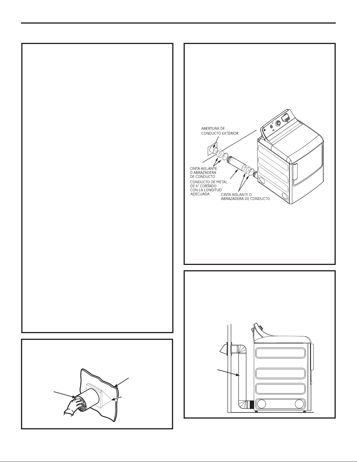
Conducto de
transición
Instrucciones de instalación
14
ANTES DE COMENZAR
4XLWHODVSHOXVDVGHODDEHUWXUDGHVDOLGD
de la pared.
Abertura de
conducto
interno
Pared
Verifique que
el regulador de tiro
de la campana
de salida se abra
y cierre libremente.
SALIDA TRASERA ESTÁNDAR
Recomendamos instalar la secadora antes
que la lavadora. Esto permitirá un acceso directo
para poder efectuar la conexión de salida.
'HVOLFHHOH[WUHPRGHOFRQGXFWRGHVDOLGDKDFLD
la parte trasera de la secadora y sujete con cinta
aislante o una abrazadera de mangueras.
NOTA: Recomendamos el uso de un conducto de
salida rígido de metal. Sin embargo, si se usan
conductos flexibles
éstos deben ser de metal
DSUREDGRVSRU8/QRGHSOiVWLFR
Para una instalación en línea recta, conecte
la salida de la secadora a la pared con cinta
aislante o una abrazadera de mangueras.
CONFIGURACIÓN RECOMENDADA
PARA MINIMIZAR LAS OBSTRUCCIONES
DE LA SALIDA
El uso de codos evitará que los conductos
se tuerzan y caigan.
CAMPANA O CUBIERTA DE PARED
Instale la salida de modo de evitar contracorrientes
RHOLQJUHVRGHSiMDURVXRWURVLQVHFWRVRDQLPDOHV
La boca de salida debe presentar una resistencia
mínima al flujo de salida y debe requerir poco
mantenimiento para evitar las obstrucciones.
Las cubiertas de pared deben instalarse por lo
menos a 12” sobre el nivel del suelo o cualquier
otra obstrucción con la abertura apuntando
KDFLDDEDMR
SEPARACIÓN DE CURVAS
Para un mejor desempeño, separe todas las
curvas con 4 pies de conducto recto como
mínimo, incluyendo la distancia entre la última
curva y la cubierta de pared con regulador de tiro.
SELLADO DE JUNTAS
Todas las juntas deben estar bien selladas
SDUDHYLWDUSpUGLGDV(OH[WUHPRPDFKRGHFDGD
sección de conducto debe apuntar en dirección
opuesta de la secadora.
/DVMXQWDVGHORVFRQGXFWRVGHEHQVHUKHUPpWLFDV
DODLUH\DODKXPHGDGPHGLDQWHODVXSHUSRVLFLyQ
de juntas con cinta aislante o cinta de aluminio.
No ensamble la tubería con tensores que se extiendan
sobre el conducto. Estos tensores acumulan pelusa,
creando un posible riesgo de incendio.
/RVWUDPRVKRUL]RQWDOHVGHEHQWHQHUXQD
LQFOLQDFLyQKDFLDHOH[WHULRUGHµSRUSLH
Incluya un acceso para inspección y limpieza del
sistema de salida, especialmente en las curvas.
Inspeccione y limpie el conducto por lo menos una
vez al año.
AISLACIÓN
Los conductos instalados a través de una
iUHDVLQFDOHIDFFLyQRXELFDGRVFHUFDGHXQ
acondicionador de aire deben aislarse para reducir
la condensación y la acumulación de pelusas.
LISTA DE CONTROL DEL SISTEMA DE
SALIDA
SALIDA AL EXTERIOR DE LA SECADORA (cont.)
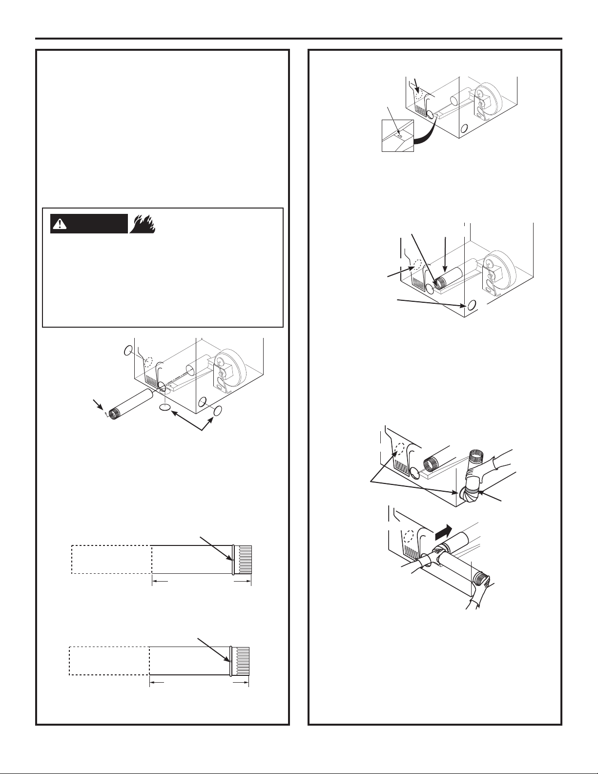
Instrucciones de instalación
15
VENTILACIÓN LATERAL O POR LA PARTE
INFERIOR
La secadora cuenta con una salida hacia la
derecha del gabinete sólo en modelos eléctricos.
La secadora cuenta con una salida hacia la
izquierda del gabinete en modelos a gas y
eléctricos.
La secadora cuenta con una salida por
la parte inferior del gabinete en modelos
a gas y eléctricos.
UBICACIÓN DE LA LENGÜETA
A través de la abertura trasera, ubique la lengüeta
en el medio de la base del artefacto. Levante la
OHQJHWDKDVWDDOUHGHGRUGHXWLOL]DQGRXQ
destornillador de lados planos.
CÓMO AGREGAR UN CONDUCTO NUEVO
Cierre la abertura trasera con la placa protectora
(Kit WE1M454).
Desconecte la secadora del suministro eléctrico.
Use guantes y protectores para brazos.
6LHVWRQRVHFXPSOHVHSRGUiSURGXFLUXQD
incendio, descarga eléctrica o laceraciones.
ADVERTENCIA
- Riesgo de incendio
Vuelva a conectar la porción cortada “A” del
conducto a la caja del ventilador. Asegúrese de que
HOFRQGXFWRPiVFRUWRVHHQFXHQWUHDOLQHDGRFRQOD
lengüeta de la base. Utilice el tornillo conservado con
anterioridad para sujetar el conducto en su lugar a
través de la lengüeta de la base del artefacto.
CÓMO AGREGAR CODOS Y CONDUCTOS DE
SALIDA HACIA DEL GABINETE
Corte el conducto como puede verse y conserve
la porción A.
Para los modelos GTD60, GTD65 y GTD68
solamente, use la dimensión de abajo.
Orificio de montaje
A
9-1/2” (24.13cm)
Orificio de montaje
A
10-1/2” (26.67cm)
'HVSHJXH\TXLWHODWDSDGHUHFKDVyORmodelos
a eléctrico), izquierda o por la parte
inferior según
FRUUHVSRQGD4XLWHHOWRUQLOORXELFDGR
dentro del
conducto de salida de la secadora y consérvelo.
Saque el conducto de la secadora.
4XLWHHO
tornillo y
consérvelo
4XLWHODWDSD
deseada (sólo una)
'HUHFKD
(sólo
modelos a
eléctrico)
Izquierda
Parte
inferior
BEND TAB
UP 45
o
Gire la
lengüeta
KDVWD
No para gas
Arme previamente un codo de 4” con un
conducto de 4”. Coloque cinta aislante alrededor
de la junta.
Introduzca el montaje del conducto, el codo
primero, a través de la abertura lateral y conecte
el codo al conducto interno de la secadora.
Asegúrese de no tirar o dañar los cables eléctricos
ubicados dentro de la secadora cuando introduzca
el conducto.
Porción “A”
'HUHFKDVyOR
modelos a
eléctrico) o salida
del lado izquierdo
Orificio de
montaje
'HUHFKD
Izquierdo
La salida
puede
agregarse
a los lados
GHUHFKD
(sólo
modelos a
eléctrico) o
izquierdo
Cinta aislante
Izquierdo
'HUHFKD
Izquierdo
'HUHFKD
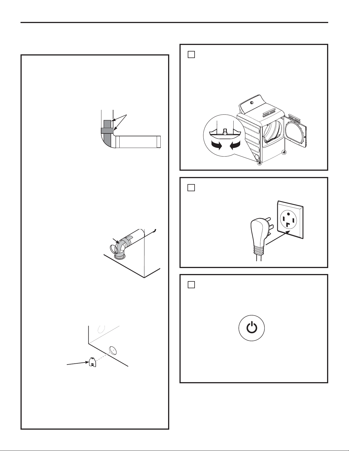
Instrucciones de instalación
16
VENTILACIÓN LATERAL O POR LA PARTE
INFERIOR (cont.)
&RQHFWHORVFRGRV\FRQGXFWRVGHPHWDOHVWiQGDU
para completar el sistema de salida. Cubra
la abertura trasera con la placa (Kit WE1M454),
disponible en su proveedor de servicios local.
Coloque la secadora en su ubicación final.
Placa
(Kit WE1M454)
Aplique cinta aislante
como puede verse en la
junta entre el conducto
interno de la secadora y
el codo, y también en
la junta entre el codo
y el conducto lateral.
Utilice sólo un conducto rígido de metal de un
diámetro de 4” dentro del gabinete de la secadora.
Las juntas del conducto interno deben sujetarse
con cinta; caso contrario, pueden separarse y
provocar un riesgo de seguridad.
NUNCA DEJE LA ABERTURA TRASERA
SIN LA PLACA EN SU LUGAR.
(Kit WE1M454.)
CÓMO AGREGAR LA PLACA DE CUBIERTA
A LA PARTE TRASERA DEL GABINETE
CÓMO AGREGAR CODOS Y CONDUCTOS
DE SALIDA HACIA LA IZQUIERDA O DERECHA
DEL GABINETE (cont.)
DUCT
TAPE
Cinta
aislante
Introduzca el codo a través de la abertura trasera
y conéctelo al conducto interno de la secadora.
Aplique cinta aislante
como puede verse en la
junta entre el conducto
interno de la secadora y
el codo, y también en la
junta entre el codo y el
conducto inferior.
Las juntas del conducto interno deben sujetarse
con cinta; caso contrario, pueden separarse y
provocar un riesgo de seguridad.
Cinta
aislante
CÓMO AGREGAR UN CODO DE SALIDA A TRAVÉS DE
LA PARTE INFERIOR DEL GABINETE
NIVELE LA SECADORA
Bajar
Elevar
ENCHUFE LA SECADORA
1
CONFIGURACIÓN FINAL
2
INICIO DE LA SECADORA
Presione el botón Power (Encendido).
NOTA:6LODVHFDGRUDKDVLGRH[SXHVWDDWHPSHUDWXUDV
bajo cero por un período prolongado, deje que suba
la temperatura antes de presionar Power. De otra
PDQHUDODSDQWDOODQRVHHQFHQGHUi
6XVHFDGRUD\DHVWiOLVWDSDUDXVDU
3
SALIDA AL EXTERIOR DE LA
SECADORA (cont.)
Coloque la secadora en posición vertical cerca
de la ubicación definitiva y ajuste las cuatro patas
niveladoras para garantizar que la secadora
se encuentre nivelada de lado a lado y del frente
a la parte trasera.
9HULILTXHTXHKD\D
una conexión a tierra
adecuada antes del uso.
Power
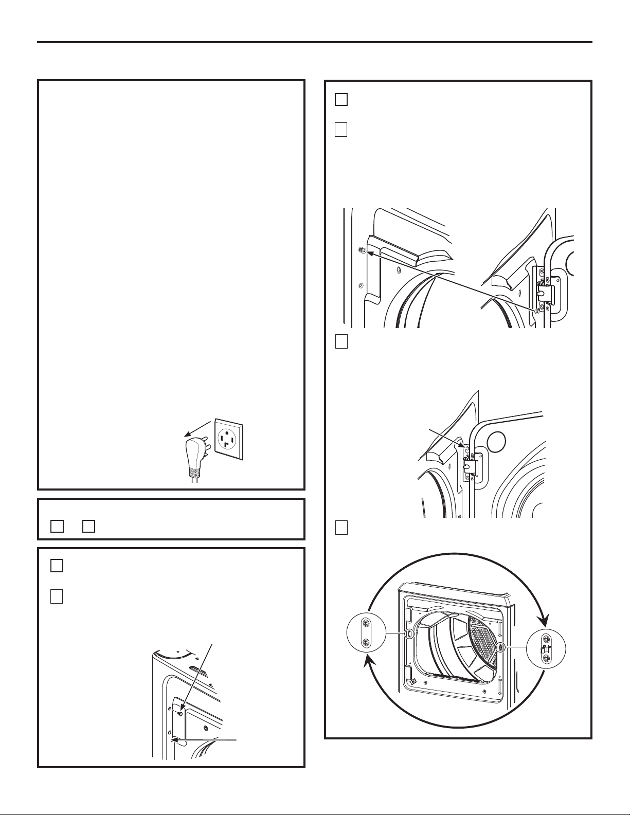
Instrucciones de instalación
17
INVERSIÓN DE LA PUERTA
Cómo cambiar el sentido de apertura
de la puerta.
NOTAS IMPORTANTES:
Lea todas las instrucciones antes de comenzar.
Manipule las piezas con cuidado para evitar rayar
la pintura.
Coloque los tornillos cercanos a sus piezas
correspondientes para evitar utilizarlos en los
lugares incorrectos.
Coloque las puertas en una superficie de trabajo
que no produzca ralladuras.
El tiempo normal necesario para invertir el
sentido de la puerta es de 30 a 60 minutos.
IMPORTANTE:
8QDYH]TXHFRPLHQFHQRPXHYDHOJDELQHWHKDVWD
TXHKD\DFRPSOHWDGRHOFDPELRGHODSXHUWD(VWDV
instrucciones indican cómo cambiar las bisagras del
ODGRGHUHFKRDOODGRL]TXLHUGR(QFDVRTXHGHVHH
FDPELDUODVQXHYDPHQWHDOODGRGHUHFKRVLJDODV
mismas instrucciones e invierta todas las referencias
GHL]TXLHUGD\GHUHFKD
Herramientas que necesitará:
'HVWRUQLOODGR3KLOOLSV1(VWiQGDU
(VSiWXODFRQODSXQWDFXELHUWDFRQFLQWD
Destornillador de punta plana pequeña
Antes de Comenzar
'HVHQFKXIHODVHFDGRUDGHO
tomacorriente.
A
INVERSIÓN DE LA PUERTA - MODELOS DE
PUERTA SÓLIDA
1
Abra la puerta aproximadamente 130 grados. Con
XQDHVSiWXODUHWLUHODVWDSDVGHSOiVWLFRXELFDGDV
a lo largo del lado izquierdo del panel frontal y deje
las mismas a un costado.
3
Afloje cada tornillo de la bisagra superior en el lado
GHUHFKR. Retire la puerta y coloque la misma sobre
una superficie plana protegida a fin de evitar
cualquier daño.
4
Retire la placa ciega y la placa de refuerzo e instale
las mismas en posiciones opuestas.
A
INVERSIÓN DE LA PUERTA - MODELOS DE
PUERTA SÓLIDA (cont.)
2
5HWLUHHOWRUQLOORLQIHULRUGHFDGDELVDJUDODGRGHUHFKR
e inserte parcialmente en los agujeros de las bisagras
del lado superior izquierdo.
NOTA: Los 4 tornillos de la bisagra del panel frontal
HVWDUiQDKRUDHQORVDJXMHURVGHODELVDJUDVXSHULRU
²VREUHODL]TXLHUGD\VREUHODGHUHFKD
Elija las INVERSIÓN DE LA PUERTA instrucciones
A
or
B
para su modelo.
7DSDGHSOiVWLFR
Lado izquierdo
del panel frontal
Placa
ciega
Placa de
refuerzo
Afloje cada
tornillo de la
bisagra superior
en el lado
GHUHFKR.
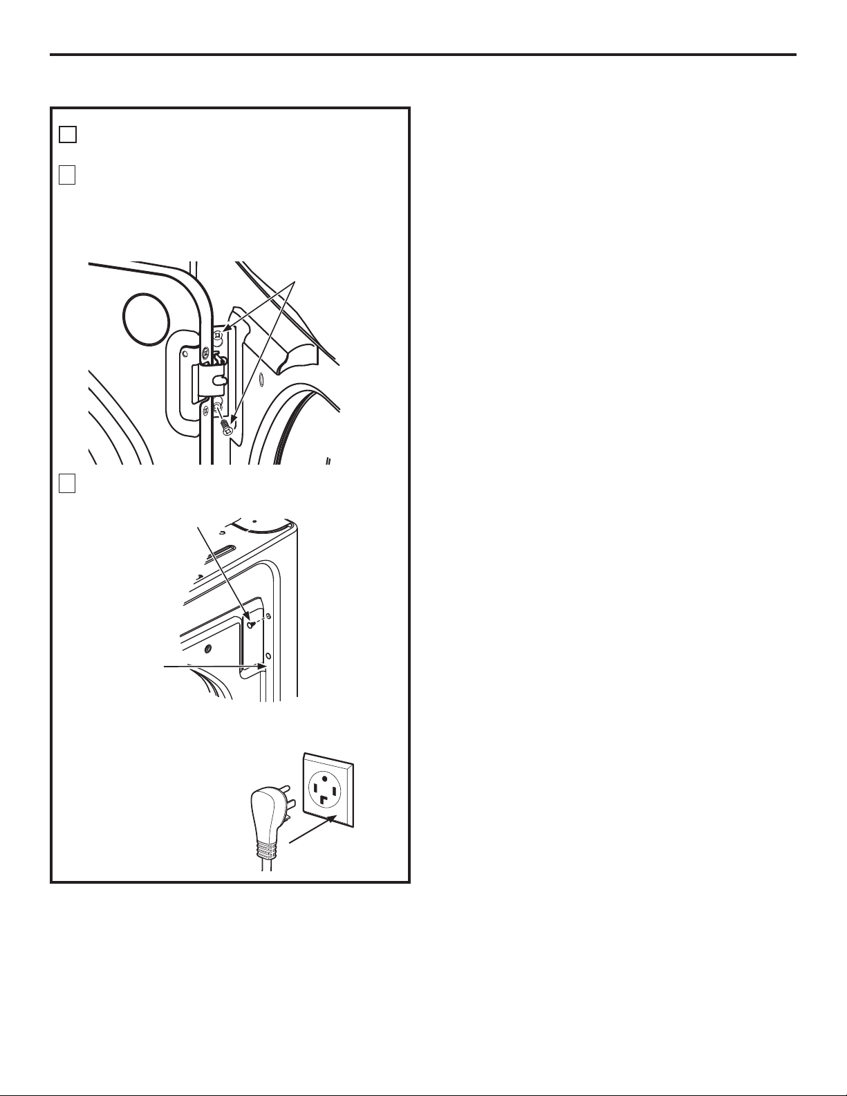
Instrucciones de instalación
18
A
INVERSIÓN DE LA PUERTA - MODELOS DE
PUERTA SÓLIDA (cont.)
5
Monte la puerta sobre los 2 tornillos superiores del
lado izquierdo, instalados en el paso 2. Mueva los
WRUQLOORVGHODELVDJUDDIORMDGRVHQHOSDVRKDFLDORV
agujeros inferiores del lado izquierdo y apriete
firmemente los cuatro tornillos.
6
,QVWDOHODVFXDWURWDSDVGHSOiVWLFRUHWLUDGDVHQHO
SDVRHQORVDJXMHURVGHOSDQHOIURQWDOGHUHFKR
NOTA: Para regresar la puerta a la configuración original,
siga estas instrucciones, cambiando entre la “izquierda” y
OD´GHUHFKDµ
Al finalizar
9XHOYDDHQFKXIDUODVHFDGRUD
en la salida eléctrica.
Puerta
Sostenga la
puerta y ajuste
los tornillos
Tapa de
SOiVWLFR
Lado GHUHFKR
del panel
frontal
INVERSIÓN DE LA PUERTA (cont.)
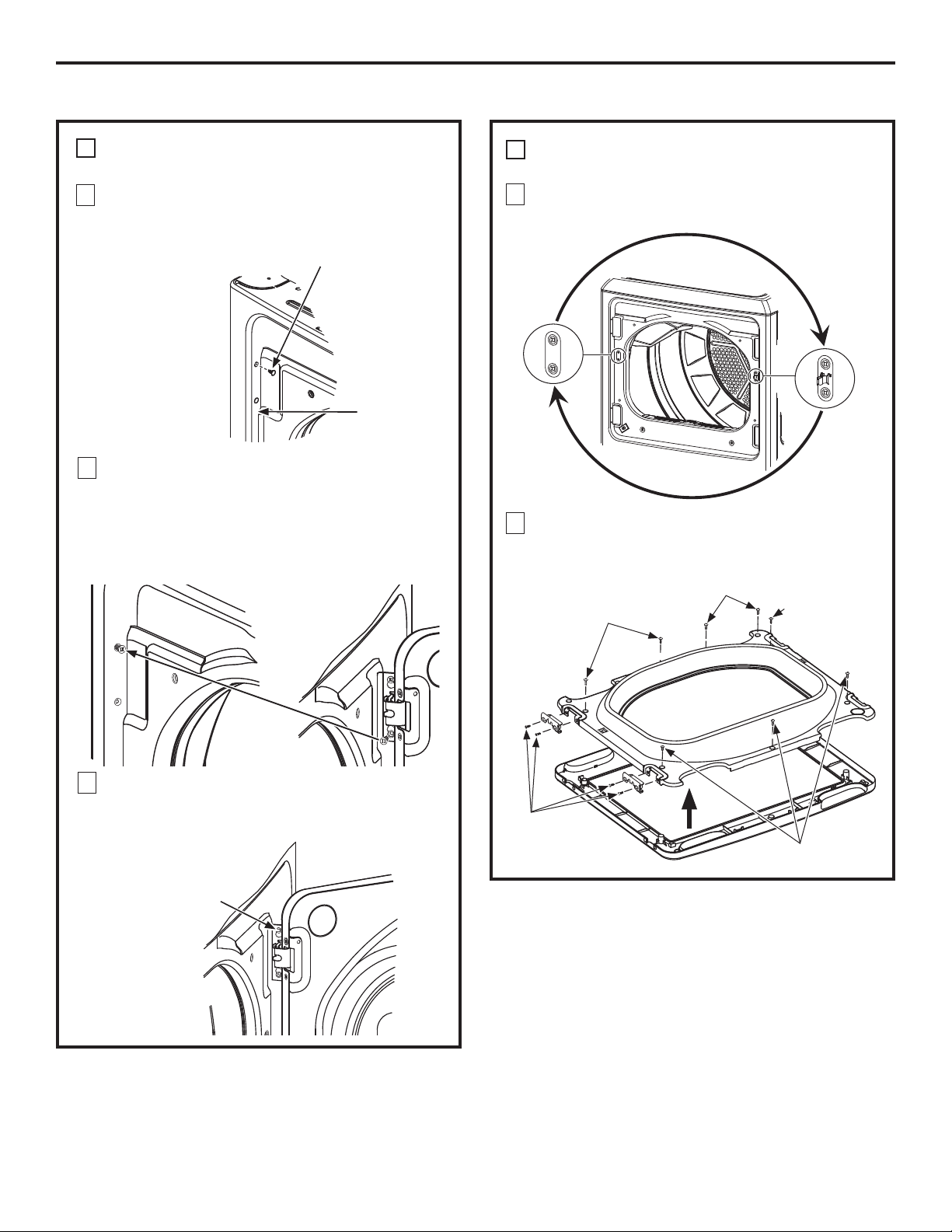
Instrucciones de instalación
19
B
INVERSIÓN DE LA PUERTA - MODELOS CON
PANEL DE CRISTAL
1
Abra la puerta aproximadamente 130 grados. Con
XQDHVSiWXODUHWLUHODVWDSDVGHSOiVWLFRXELFDGDV
a lo largo del lado izquierdo del panel frontal y deje
las mismas a un costado.
5
4XLWHORVWRUQLOORVGHODELVDJUDGHODSXHUWDORV
tornillos del interior y los 2 tornillos bolsillo. Levante la
puerta interior con un destornillador de punta plana.
B
INVERSIÓN DE LA PUERTA - MODELOS CON
PANEL DE CRISTAL (cont.)
4
Retire la placa ciega y la placa de refuerzo e instale
las mismas en posiciones opuestas.
7DSDGHSOiVWLFR
Lado izquierdo
del panel frontal
Placa
ciega
Placa de
refuerzo
3
Afloje cada tornillo de la bisagra superior en el lado
GHUHFKR. Retire la puerta y coloque la misma sobre
una superficie plana protegida a fin de evitar
cualquier daño.
2
5HWLUHHOWRUQLOORLQIHULRUGHFDGDELVDJUDODGRGHUHFKR
e inserte parcialmente en los agujeros de las bisagras
del lado superior izquierdo.
NOTA: Los 4 tornillos de la bisagra del panel frontal
HVWDUiQDKRUDHQORVDJXMHURVGHODELVDJUDVXSHULRU
²VREUHODL]TXLHUGD\VREUHODGHUHFKD
Afloje cada
tornillo de la
bisagra superior
en el lado
GHUHFKR.
Puerta interna
Puerta
externa
Tornillos
internos
Tornillos
internos
Tornillos bolsillo
Tornillo
interno
Tornillos de
las bisagras
de la puerta
INVERSIÓN DE LA PUERTA
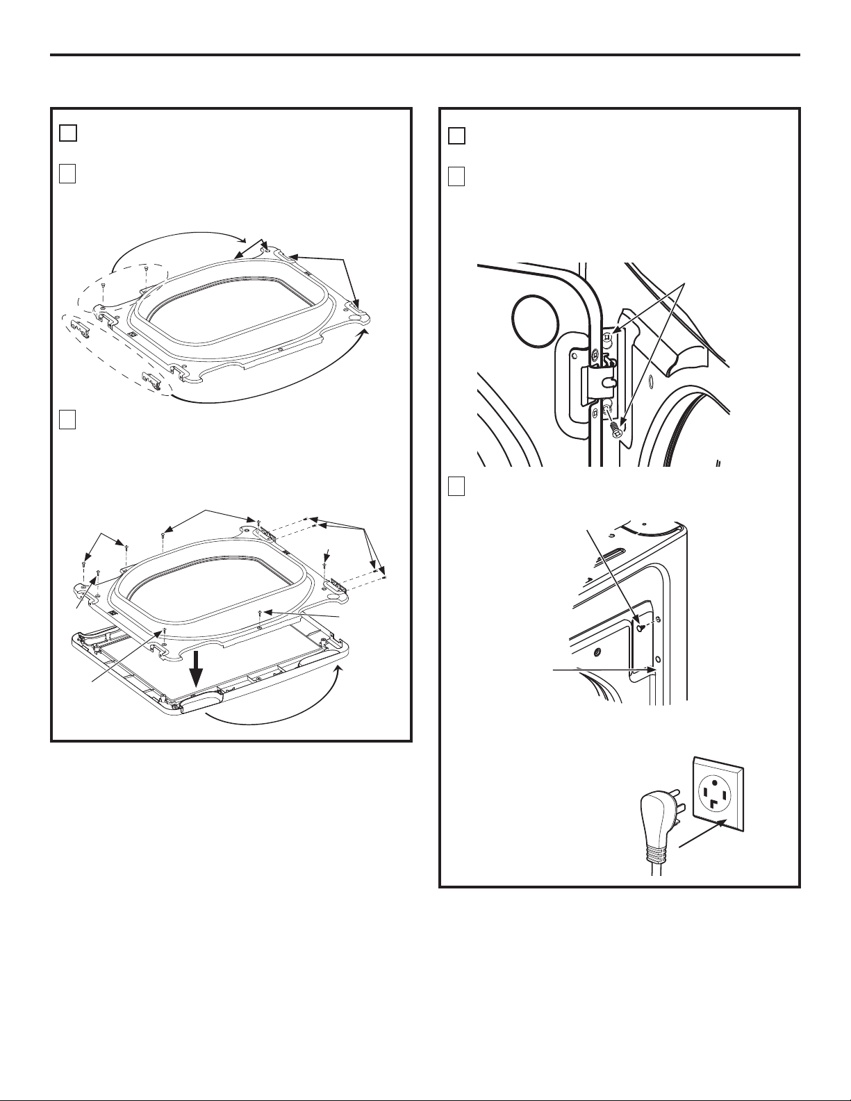
Instrucciones de instalación
20
INVERSIÓN DE LA PUERTA (cont.)
B
INVERSIÓN DE LA PUERTA - MODELOS CON
PANEL DE CRISTAL (cont.)
8
Monte la puerta sobre los 2 tornillos superiores del
lado izquierdo, instalados en el paso 2. Mueva los
WRUQLOORVGHODELVDJUDDIORMDGRVHQHOSDVRKDFLDORV
agujeros inferiores del lado izquierdo y apriete
firmemente los cuatro tornillos.
9
,QVWDOHODVFXDWURWDSDVGHSOiVWLFRUHWLUDGDVHQHO
SDVRHQORVDJXMHURVGHOSDQHOIURQWDOGHUHFKR
NOTA: Para regresar la puerta a la configuración original,
siga estas instrucciones, cambiando entre la “izquierda” y
OD´GHUHFKDµ
Al finalizar
9XHOYDDHQFKXIDUODVHFDGRUD
en la salida eléctrica.
Puerta
Sostenga la
puerta y ajuste
los tornillos
Tapa de
SOiVWLFR
Lado GHUHFKR
del panel
frontal
B
INVERSIÓN DE LA PUERTA - MODELOS CON
PANEL DE CRISTAL (cont.)
6
4XLWH\FDPELHODVWDSDVGHSOiVWLFRy la bisagras
de la puerta exterior.
7
Gire la puerta exterior de 180°, instale la puerta
trasera interior en el exterior de la puerta con los
tornillos que retiró en el paso 5. Asegúrese de montar
las bisagras en el lado opuesto de bolsillo.
Instalar bisagras
de lado opuesto
aquí
Instale las tapas de
SOiVWLFRGHXQODGR
opuesto aquí
Tapas
Bisagras
Puerta interna
Puerta interna
Puerta
externa
Gire la puerta
exterior de
180°
Tornillo
interno
Tornillos
internos
Tornillos
bolsillo
Tornillo
interno
Tornillos
de las
bisagras
de la
puerta
Tornillo interno
Tornillo
interno