
CBEP PELLET STOVE
INSTALLATION & OPERATION MANUAL
CAUTION
Please read this entire manual before installation and use of this pellet fuel-
burning appliance. Keep children, furniture, fixtures and all combustibles away
from an
y
heatin
g
appliance.
SAFETY NOTICE
Failure to follow these instructions can result in property damage, bodily injury
or even death. For your safety and protection, follow the installation
instructions outlined in this manual. Contact your local building or fire officials
about restrictions and installation inspection requirements (including permits) in
y
our area.
SAVE THESE INSTRUCTIONS
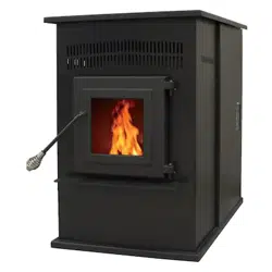
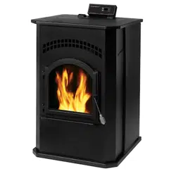
MODELS 25-CBEP 55-SHPCBEP 55-TRPCBEP
www.heatredefined.com
Parts: (800) 516-3636
Support: (800) 245-6489
Manufactured By:
England’s Stove Works,
Inc.
PO Box 206
Monroe, VA 24574
Rev. 1/2019

2
IMPORTANT! READ AND FOLLOW ALL INSTALLATION AND MAINTENANCE INSTRUCTIONS, INCLUDING
CLEANING THE UNIT AS SPECIFIED, AND REPLACING GASKETS ANNUALLY, AND PARTS AS NEEDED.
ENGLAND’S STOVE WORKS IS NOT RESPONSIBLE FOR ANY DAMAGE OR INJURY INCURRED DUE TO NEGLECT, OR
DUE TO UNSAFE INSTALLATION OR USAGE OF THIS PRODUCT. CALL TECHNICAL SUPPORT WITH QUESTIONS.
WARNING:
Use of outside combustion air is mandatory with this unit.
Do not operate with the hopper open; lid must be shut and
tightly latched during operation.
Retain for your files
Model Number________________________
Date of Purchase_______________________
Date of Manufacture____________________
Serial Number_________________________
* This information can be found on the safety tag attached to the underside of the
hopper lid. Have this information on hand if you phone the factory or your dealer
regarding this product.
IMPORTANT: IF YOU HAVE A PROBLEM WITH THIS
UNIT, DO NOT RETURN IT TO THE DEALER. CONTACT
TECHNICAL SUPPORT @ 1-800-245-6489
Note: England’s Stove Works does not recommend using a
p
ellet stove as
y
our onl
y
source of heat.
Mobile Home Use:
This freestanding pellet unit is approved for mobile home or
doublewide installation with the outside combustion air hook-
up. See the “Installation” section of this manual for details
pertaining to mobile home installations. Mobile home
installation must be in accordance with the Manufactured Home
and Safety Standard (HUD), CFR 3280, Part 24.

3
IMPORTANT! READ AND FOLLOW ALL INSTALLATION AND MAINTENANCE INSTRUCTIONS, INCLUDING
CLEANING THE UNIT AS SPECIFIED, AND REPLACING GASKETS ANNUALLY, AND PARTS AS NEEDED.
ENGLAND’S STOVE WORKS IS NOT RESPONSIBLE FOR ANY DAMAGE OR INJURY INCURRED DUE TO NEGLECT, OR
DUE TO UNSAFE INSTALLATION OR USAGE OF THIS PRODUCT. CALL TECHNICAL SUPPORT WITH QUESTIONS.
WWELCOME!
Introduction
Thank You ....................................4
Specifications
Heating Specifications ..................5
EPA Compliance ...........................5
Dimensions ...................................5
Installation
Installation Overview ....................6
Clearances to Combustibles ..........7
Venting Introduction .....................8
Venting Guidelines .......................8
Additional Venting Information ...9
Vent Termination Clearances .....10
Approved Venting Methods
o Through the Wall ............11
o Through the Ceiling ........12
o Existing Chimney............13
Mobile Home Installation ...........14
Outside Air Hook-Up ..................15
Floor Protection ..........................16
Daily Operation
Getting Started ............................17
Lighting a Fire.............................17
Control Board Settings ................19
Error Codes .................................20
Power Failure ..............................21
Thermostat Installation ...............22
Thermostat Operation .................23
Maintenance
Daily
o Important Notes ..............24
o Daily Ash Removal .........25
o Cleaning the Burnpot ......26
Bi-Weekly
o Important Notes ..............27
o Exhaust Cover Removal .28
Monthly
o Important Notes ..............30
o Venting Pipe....................31
Yearly
o Important Notes ..............32
o Exhaust Blower ...............33
o Convection Blower .........35
o Hopper Fines ...................35
o Checking Gaskets............36
Troubleshooting Guide
Troubleshooting ..........................37
Replacing Components
Auger Motor................................39
Convection Blower .....................40
Combustion Blower ....................40
Vacuum Switch ...........................41
Igniter ..........................................41
Gaskets ........................................42
Finish...........................................42
Glass ............................................42
Control Board..............................43
Wiring Diagram ..........................44
Standard & Optional Accessories
Thermostat ..................................45
Air Wash .....................................45
Illustrated Parts Detail
Exploded Parts Diagram .............46
Parts List .....................................47
Sample Safety Tag ......................48
Warranty
Warranty Details .........................49
Warranty Reg. Form ...................51
EPA & Safety ………..…………….53

4
IMPORTANT! READ AND FOLLOW ALL INSTALLATION AND MAINTENANCE INSTRUCTIONS, INCLUDING
CLEANING THE UNIT AS SPECIFIED, AND REPLACING GASKETS ANNUALLY, AND PARTS AS NEEDED.
ENGLAND’S STOVE WORKS IS NOT RESPONSIBLE FOR ANY DAMAGE OR INJURY INCURRED DUE TO NEGLECT, OR
DUE TO UNSAFE INSTALLATION OR USAGE OF THIS PRODUCT. CALL TECHNICAL SUPPORT WITH QUESTIONS.
INTRODUCTION
ThankyouforpurchasingthisfineproductfromEngland’sStoveWorks!
England’sStoveWorkswasstarted,andisstillownedby,afamilythatbelieves
stronglyina“DoItYourself”spirit;that’sonereasonyoufoundthisproductat
yourfavorite“DoItYourself”store.
Weintentionallydesignandbuild
ourstovessothatanyhomeownercan
maintaintheirstovewithbasictools,andwe’realwaysmorethanhappytohelp
youdothejobaseasilyandasinexpensivelyaspossible.However,while
remainingsimple,ourstovesaredesignedtoperformextremelyefficiently,
helpingdelivermoreheatfromless
fuel.
PleaselookattheextensiveHelpsectiononourwebsiteandcallourTechnical
SupportDepartmentat(800)245‐6489ifyouneedanyhe lpwithyourstove.We
arenearlyalwaysableto“walkyouthrough”anyinstallationissues,repairs,
problemsorotherquestionsthatyoumayhave.
Wishingyouyearsofefficient,qualityand“comfy”heating,
EveryoneatEngland’sStoveWorks
PleaseNote:Whileinformationobtainedfromourwebsiteandthroughour
TechnicalSupportlineisalwaysfreeofcharge,therewillbeaservicecharge
incurredwithany“on‐site”repairsormaintenancethatwemayarrange.
Thismanualencompassesallversionsofthe25‐CBEP,includingthe55‐SHPCBEPandthe55‐
TRPCBPEP.However,forsimplicityofdescription,thestovewillbereferredtobythegeneric
25‐CBEPdesignation.
This manual is available for free download on the manufacturer’s web site. It is a copyrighted document and
resale is strictly prohibited. The manufacturer may update this manual occasionally and cannot be responsible
for problems including injuries or damages resulting from the use of information found in any manual from
unauthorized sources.
CAUTION: Stove is heavy.
In addition, when handling any sheet metal products, be aware that there may be sharp edges or burrs.
Although we make every effort to eliminate any sharp edges, please use caution when handling any metal parts.
Remember to disconnect (unplug) the stove from the power source and allow it to completely cool down
b
efore
p
erformin
g
an
y
maintenance.
5
IMPORTANT! READ AND FOLLOW ALL INSTALLATION AND MAINTENANCE INSTRUCTIONS, INCLUDING
CLEANING THE UNIT AS SPECIFIED, AND REPLACING GASKETS ANNUALLY, AND PARTS AS NEEDED.
ENGLAND’S STOVE WORKS IS NOT RESPONSIBLE FOR ANY DAMAGE OR INJURY INCURRED DUE TO NEGLECT, OR
DUE TO UNSAFE INSTALLATION OR USAGE OF THIS PRODUCT. CALL TECHNICAL SUPPORT WITH QUESTIONS.
SPECIFICATIONS
Heating Specifications
Heat Output Range** .............................................. 7,918 BTU/hr – 15,318 BTU/hr
Approximate Pellet Burn Rate** ................................................................ 3.7 lb/hr
Maximum Burn Time** .............................................................................. 30 hours
Approximate Square Footage Heated*** ...................................... 800 - 2000 sq. ft.
Hopper Capacity ....................................................................................... 45 pounds
EPA and Safety Compliance Specifications
EPA Compliance ………………………Certified to comply with 2020 particulate
emissions standards using pellet fuel.
U.S. Test Standard: US EPA 40 CFR Part 60, Subpart 60.536
Particulate Emissions ........................................................................ 1.030 grams/hr
Efficiency* ........................................................................................................ 63 %
Tested To ....................................................... UL 1482, ULC S627, ASTM E 1509
*- HHV overall result.
** - Heat output, burn rate and maximum burn time are heavily dependent on the type of pellets burned in the stove;
as such, these numbers may vary.
*** - The maximum heating capacity of this unit can vary greatly based on climate, construction style, insulation
and a myriad of other factors. Use this information in conjunction with a BTU loss calculation for your home to
determine if this unit will be sufficient for your needs.
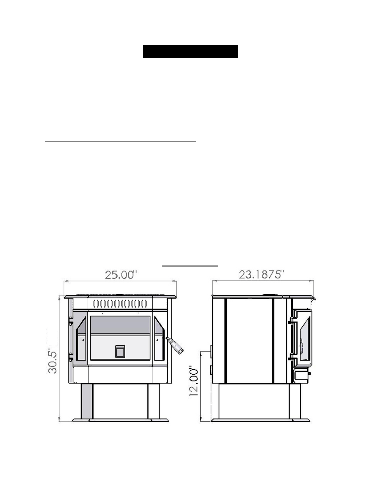
DIMENSIONS
6
IMPORTANT! READ AND FOLLOW ALL INSTALLATION AND MAINTENANCE INSTRUCTIONS, INCLUDING
CLEANING THE UNIT AS SPECIFIED, AND REPLACING GASKETS ANNUALLY, AND PARTS AS NEEDED.
ENGLAND’S STOVE WORKS IS NOT RESPONSIBLE FOR ANY DAMAGE OR INJURY INCURRED DUE TO NEGLECT, OR
DUE TO UNSAFE INSTALLATION OR USAGE OF THIS PRODUCT. CALL TECHNICAL SUPPORT WITH QUESTIONS.
INSTALLATION
Installation Overview
When choosing a location for your new stove, there are a multitude of
factors that should be taken into account before beginning the installation.
1. Traffic Patterns – To help prevent accidents, the stove should be placed
in a location where it is out of the way of normal travel through the
home.
2. Heat Flow – When deciding on a location for the stove, consider the way
heat moves throughout your home. Install the stove where you need the
heat; basement installations often do not allow sufficient heat to flow to
the upper floors and a top floor installation will not allow any heat to
reach the floors below. Always consider that heat rises and will take the
path of least resistance while it is still hot.
3. Exhaust Location – Outside walls are generally the best place to install a
stove, since they allow easy exhaust and intake air installation (using our
DuraVent AC-3000 Kit, AC-33000 if Canada). If there is not a feasible
way to install the stove on an outside wall, there are methods for venting
the stove up through the roof, but they tend to be more costly because
they involve the use of more pellet vent pipe and can often make outside
air installation more difficult.
4. Wall Construction – Locating the stove so that the exhaust system can
pass between studs will simplify the installation and eliminate the need to
reframe any sections of the wall to accommodate the wall thimble.
WARNING
Do not store or use gasoline or other flammable vapors and liquids in the
vicinity of this or any other appliance.
Do Not Overfire – If any external part starts to glow, you are overfiring.
Reduce feed rate. Overfiring will void your warranty.
Comply with all minimum clearances to combustibles as specified.
Failure to comply may result in a house fire.
Tested and approved for wood pellets only. Burning any other fuel will
void
y
our warrant
y
.
7
IMPORTANT! READ AND FOLLOW ALL INSTALLATION AND MAINTENANCE INSTRUCTIONS, INCLUDING
CLEANING THE UNIT AS SPECIFIED, AND REPLACING GASKETS ANNUALLY, AND PARTS AS NEEDED.
ENGLAND’S STOVE WORKS IS NOT RESPONSIBLE FOR ANY DAMAGE OR INJURY INCURRED DUE TO NEGLECT, OR
DUE TO UNSAFE INSTALLATION OR USAGE OF THIS PRODUCT. CALL TECHNICAL SUPPORT WITH QUESTIONS.
INSTALLATION
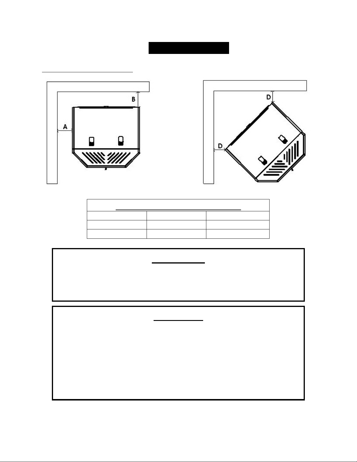
Clearances to Combustibles
UnitClearancestoCombustibles
Side(A) Rear(B) Corner(D)
6IN. 6IN. 6IN.
152MM. 152MM. 152MM.
Note: Leaving 6 in. clearance also gives room for easier cleaning and maintenance
WARNING
INSTALL VENT AT CLEARANCES SPECIFIED BY THE VENT
MANUFACTURER.
HOT! Do not touch! Severe burns or clothing ignition may result.
Glass and other surfaces are hot during operation.
CAUTION
Keep children away.
Supervise children in the same room as this appliance.
Alert children and adults to the hazards of high temperatures.
Do NOT operate with protective barriers open or removed.
Keep clothing, furniture, draperies and other combustibles away.
Installation MUST comply with local, regional, state and national codes and
regulations.
Consult local building, fire officials or authorities having jurisdiction about
restrictions, installation ins
p
ection, and
p
ermits.

8
IMPORTANT! READ AND FOLLOW ALL INSTALLATION AND MAINTENANCE INSTRUCTIONS, INCLUDING
CLEANING THE UNIT AS SPECIFIED, AND REPLACING GASKETS ANNUALLY, AND PARTS AS NEEDED.
ENGLAND’S STOVE WORKS IS NOT RESPONSIBLE FOR ANY DAMAGE OR INJURY INCURRED DUE TO NEGLECT, OR
DUE TO UNSAFE INSTALLATION OR USAGE OF THIS PRODUCT. CALL TECHNICAL SUPPORT WITH QUESTIONS.
INSTALLATION
Venting Introduction
This pellet stove operates on a negative draft system, which pulls combustion air
through the burn pot and pushes the exhaust air to the vent pipe and out of the building. This
unit must be installed in accordance with the following detailed descriptions of venting
techniques; not installing the stove in accordance with the details listed here can result in
poor stove performance, property damage, bodily injury or death. England’s Stove Works is
not responsible for any damage incurred due to a poor or unsafe installation.
If questions arise pertaining to the safe installation of the stove, our Technical Support
line (800-245-6489) is available. Contact your local code official to be certain your
installation meets local and national fire codes and if you’re uncertain about how to safely
install the stove, we recommend contacting a local NFI certified installer to perform the
installation.
Venting Guidelines
ALWAYS install vent pipe in strict adherence with the instructions and
clearances included with your venting system.
DO NOT connect this pellet stove to a chimney flue which also serves
another appliance.
DO NOT install a flue pipe damper or any other restrictive device in the
exhaust venting system of this unit.
USE an approved wall thimble when passing through a wall and a ceiling
support/fire stop when passing through a ceiling.
ONLY use 3.0” or 4.0” Type L or Type PL pipe approved for pellet stove
venting; DO NOT use galvanized or B-Vent pipe.
SEAL each joint of pellet vent with high temperature silicone (Part # AC-
RTV3) to prevent smoke spillage into the home.
AVOID excessive horizontal runs and elbows, as both will reduce the draft
of the venting system and will result in poor stove performance.
INCLUDE as much vertical pipe as possible to prevent smoke from the unit
from entering your home in the event of a power outage.
INSPECT your venting system often, to be certain it is clear of fly-ash and
other restrictions.
CLEAN the venting system as detailed in the maintenance section of this
manual.
WARNING: Venting system surfaces get HOT, and can cause burns if
touched. Noncombustible shielding or guards may be required.

9
IMPORTANT! READ AND FOLLOW ALL INSTALLATION AND MAINTENANCE INSTRUCTIONS, INCLUDING
CLEANING THE UNIT AS SPECIFIED, AND REPLACING GASKETS ANNUALLY, AND PARTS AS NEEDED.
ENGLAND’S STOVE WORKS IS NOT RESPONSIBLE FOR ANY DAMAGE OR INJURY INCURRED DUE TO NEGLECT, OR
DUE TO UNSAFE INSTALLATION OR USAGE OF THIS PRODUCT. CALL TECHNICAL SUPPORT WITH QUESTIONS.
INSTALLATION
Additional Venting Information
Do not mix and match components from different pipe manufacturers when
assembling your venting system (i.e. Do NOT use venting pipe from one
manufacturer and a thimble from another).
We require a minimum vertical rise of 36 in. (3 ft.) of pipe to create natural
draft in the system, which helps evacuate smoke from the stove in the event
of a power failure or combustion blower failure.
Venting systems 15.0 ft. or shorter may be composed entirely of 3.0 in.
pellet pipe; to reduce frictional losses, venting systems longer than 15.0 ft.
should be composed of 4.0 in. pellet pipe.
Do not terminate the venting system directly beneath any combustible
structure such as a porch or deck.
Follow NFPA 211 rules listed below for venting system termination location
relative to windows and other openings in the dwelling (see also Vent
Termination Clearances).
o NFPA 211 (2006 ed.) Section 10.4 Termination: 10.4.5
(1) The exit terminal of a mechanical draft system other than direct
vent appliances (sealed combustion system appliances) shall be
located in accordance with the following:
(a) Not less than 3 ft. (.91 m) above any forced air inlet located
within 10 ft. (3.0m).
(b) Not less than 4 ft. (1.2 m) below, 4 ft. (1.2 m) horizontally
from or 1 ft. (305 mm) above any door, window or gravity air
inlet into any building.
(c) Not less than 2 ft. (0.61 m) from an adjacent building and
not less than 7 ft. (2.1 m) above grade when located adjacent to
public walkways.
Distance between the termination opening and grade should be a minimum
of 24 in. contingent on the grade surface below the termination. When
determining the termination height above grade, consider snow drift lines
and combustibles such as grass or leaf accumulation. In areas where
significant snowfall is possible, the termination height must be sufficiently
high to keep the termination free of snow accumulation.
10
IMPORTANT! READ AND FOLLOW ALL INSTALLATION AND MAINTENANCE INSTRUCTIONS, INCLUDING
CLEANING THE UNIT AS SPECIFIED, AND REPLACING GASKETS ANNUALLY, AND PARTS AS NEEDED.
ENGLAND’S STOVE WORKS IS NOT RESPONSIBLE FOR ANY DAMAGE OR INJURY INCURRED DUE TO NEGLECT, OR
DUE TO UNSAFE INSTALLATION OR USAGE OF THIS PRODUCT. CALL TECHNICAL SUPPORT WITH QUESTIONS.
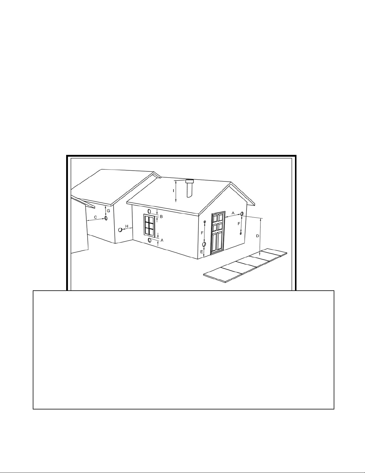
VENT TERMINATION CLEARANCES
A) MIN. 4-FT CLEARANCE BELOW OR BESIDE ANY DOOR OR WINDOW THAT OPENS.
B) MIN. 1-FT CLEARANCE ABOVE ANY DOOR OR WINDOW THAT OPENS.
C) MIN. 2-FT CLEARANCE FROM ANY ADJACENT BUILDING.
D) MIN. 7-FT CLEARANCE FROM ANY GRADE WHEN ADJACENT TO PUBLIC
WALKWAYS.
E) MIN. 2-FT CLEARANCE ABOVE ANY GRASS, PLANTS, OR OTHER COMBUSTIBLE
MATERIALS.
F) MIN. 3-FT CLEARANCE FROM A FORCED AIR INTAKE OF ANY APPLIANCE.
G) MIN. 2-FT CLEARANCE BELOW EAVES OR OVERHANG.
H) MIN. 1-FT CLEARANCE HORIZONTALLY FROM COMBUSTIBLE WALL.
I) VENTS INSTALLED WITH MECHANICAL EXHAUSTERS SHALL TERMINATE NOT LESS THAN 12 IN.
(305MM) ABOVE THE HIGHEST POINT WHERE THEY PASS THROUGH THE ROOF SURFACE.
Notes on termination of Pellet Vent Pipe from NFPA211(2006ed.)Section10.4Termination:10.4.5
(See also “INSTALLATION” section of manual AND additional notes above):
1. Not less than three (3) feet above any forced air inlet located within ten (10) feet.
2. Not less than four (4) feet below, four (4) feet horizontally from, or one (1) foot above any door,
window or gravity air inlet into any building.
3. Not less than two (2) feet from an adjacent building, and not less than seven (7) feet above
grade where located adjacent to public walkways.
The exhaust exit shall be arranged so that the flue gases are not directed so that it will affect people,
overheat combustible structures, or enter buildings. Forced draft systems and all parts of induced
draft systems under positive pressure during operation shall be installed gastight or to prevent
leakage of combustion products into a building. Through-the-wall vents shall not terminate over
public walkways, or where condensate or vapor could create hazards or a nuisance.
Be sure to follow local codes and all manufacturer’s instructions (including exhaust pipe).
Consult a professional installer and/or call Technical Support if
y
ou have an
y
questions.
11
IMPORTANT! READ AND FOLLOW ALL INSTALLATION AND MAINTENANCE INSTRUCTIONS, INCLUDING
CLEANING THE UNIT AS SPECIFIED, AND REPLACING GASKETS ANNUALLY, AND PARTS AS NEEDED.
ENGLAND’S STOVE WORKS IS NOT RESPONSIBLE FOR ANY DAMAGE OR INJURY INCURRED DUE TO NEGLECT, OR
DUE TO UNSAFE INSTALLATION OR USAGE OF THIS PRODUCT. CALL TECHNICAL SUPPORT WITH QUESTIONS.
INSTALLATION
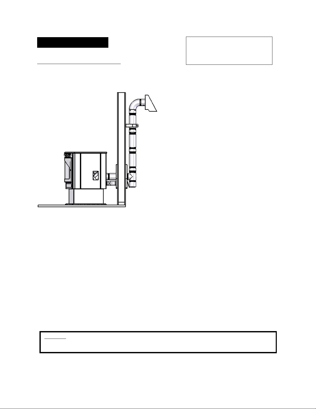
Approved Venting Method 1: Through the Wall
Generally the simplest installation
method, venting through the wall using
our AC-3000 kit, AC-33000 if Canada (or
similar venting system) is also the
preferred venting method. It minimizes
horizontal pipe, allows the stove to be
installed close to the wall and keeps the
clean-out tee on the outside of the house,
for ease of cleaning.
When installing any venting system, Type
L or Type PL pipe must be used and all
clearances to combustibles (listed by the
pipe manufacturer) must be strictly
adhered to.
Use the pipe manufacturer’s approved
thimble for passing through a combustible
wall, and maintain at least the minimum
clearances to combustibles.
Use an appliance collar where the pellet
vent connects to the exhaust output of the pellet stove and attach the appliance collar to the
exhaust blower output using three sheet metal screws.
Secure the pellet vent to the outside of the house using a wall strap just below the 90 degree
elbow.
Seal each pipe connection joint with high temperature RTV Silicone, to ensure the system is
leak free (Check with the specific venting system manufacturer’s instructions before doing
so).
If the pellet vent pipe being used is not a “Twist Lock” system, three (3) sheet metal screws
are required at each pipe joint.
Connect the pellet stove to outside combustion air using the kit included with your stove or
using an alternative method, as described in the “Outside Air” section, on page 15.
This installation type can be modified for basement (Basement installations should always
be performed by a professional installer) or other installations wherein the tee and vertical
section of the pipe would be inside the home and the venting system would simply pass
horizontally through the thimble and then terminate.
Please Note:
Installation diagrams are for reference purposes only and are not drawn to scale, nor meant to be used as plans for each individual
installation. Please follow all venting system requirements, maintain the required clearances to combustibles, and follow all local codes.
For high altitude installations
(above 4,000 ft.), the vent pipe
should be increased from 3-inch
(3”) to four-inch (4”).
12
IMPORTANT! READ AND FOLLOW ALL INSTALLATION AND MAINTENANCE INSTRUCTIONS, INCLUDING
CLEANING THE UNIT AS SPECIFIED, AND REPLACING GASKETS ANNUALLY, AND PARTS AS NEEDED.
ENGLAND’S STOVE WORKS IS NOT RESPONSIBLE FOR ANY DAMAGE OR INJURY INCURRED DUE TO NEGLECT, OR
DUE TO UNSAFE INSTALLATION OR USAGE OF THIS PRODUCT. CALL TECHNICAL SUPPORT WITH QUESTIONS.
INSTALLATION
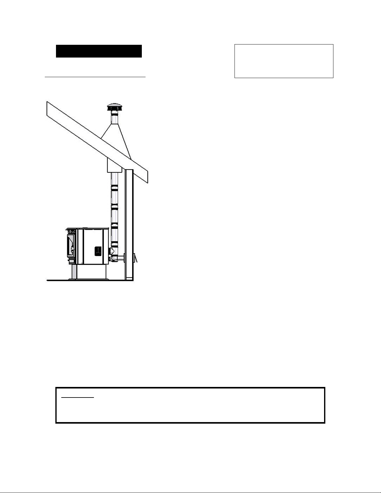
Approved Venting Method 2: Through the Ceiling
Venting through the ceiling/roof may be the only
feasible venting option in some cases and is a factory
recommended installation.
When installing any venting system, Type L or Type
PL pipe must be used and all clearances to combustibles
listed by the pipe manufacturer must be strictly adhered
to.
Use the pipe manufacturer’s approved ceiling support
for passing through a combustible ceiling, as well as the
required firestops, radiation shields, flashing and storm
collar.
Be certain to follow the manufacturer’s required height
of termination above the roof line, and maintain at least
the minimum clearances to combustibles.
Use an appliance collar where the pellet vent connects
to the exhaust output of the pellet stove and attach the
appliance collar to the exhaust blower output using three
sheet metal screws.
Seal each pipe connection joint with high temperature
RTV Silicone, to ensure the system is leak free (Check
with the specific pipe manufacturer’s instructions before
doing so).
If the pellet vent pipe being used is not a “Twist Lock” system, three (3) sheet metal screws
are required at each pipe joint.
Connect the pellet stove to outside combustion air using the kit included with your stove or
using an alternative method, as described in the “Outside Air” section, on page 15.
This venting method can also be modified so that the venting system runs horizontally
through the wall from the stove, then transitions to vertical and terminates above the roofline.
When using this modified version of this installation be certain to carefully follow the
venting system manufacturer’s instructions diligently.
Please Note:
Installation diagrams are for reference purposes only and are not drawn to scale, nor meant to be used
as plans for each individual installation. Please follow all venting system requirements, maintain the
required clearances to combustibles, and follow all local codes.
For high altitude installations
(above 4,000 ft.), the vent pipe
should be increased from 3-inch
(3”) to four-inch (4”).
13
IMPORTANT! READ AND FOLLOW ALL INSTALLATION AND MAINTENANCE INSTRUCTIONS, INCLUDING
CLEANING THE UNIT AS SPECIFIED, AND REPLACING GASKETS ANNUALLY, AND PARTS AS NEEDED.
ENGLAND’S STOVE WORKS IS NOT RESPONSIBLE FOR ANY DAMAGE OR INJURY INCURRED DUE TO NEGLECT, OR
DUE TO UNSAFE INSTALLATION OR USAGE OF THIS PRODUCT. CALL TECHNICAL SUPPORT WITH QUESTIONS.
INSTALLATION
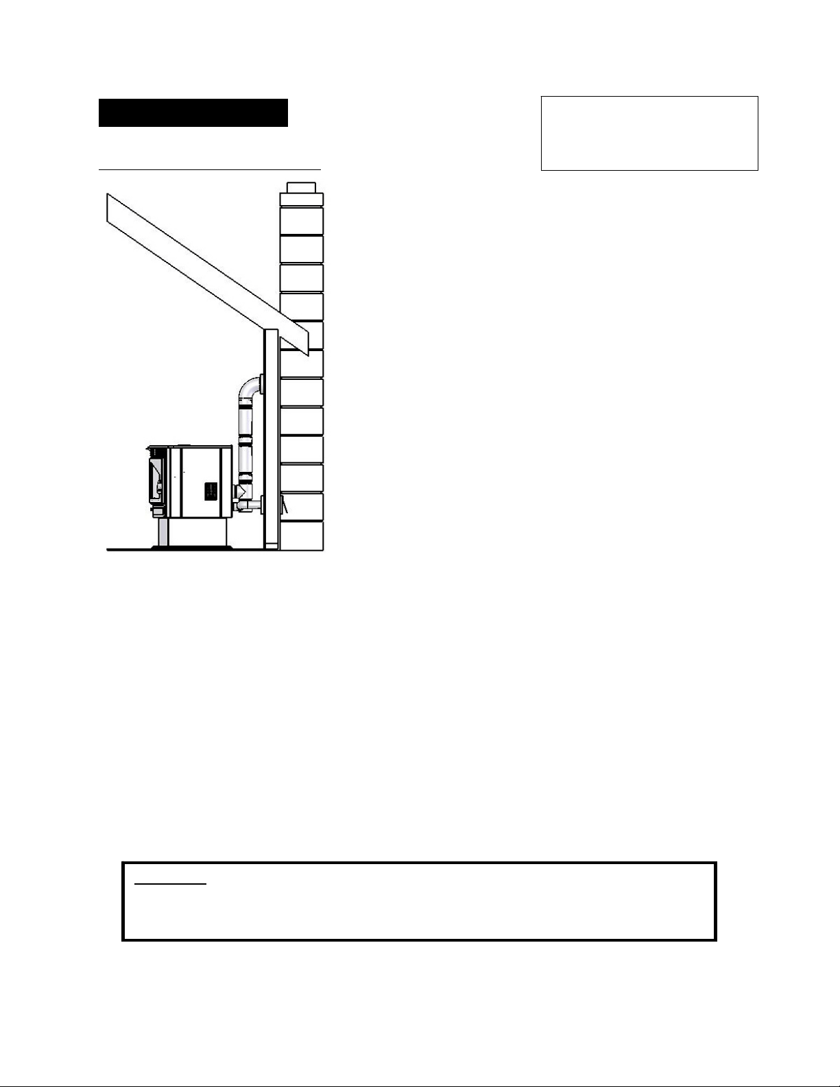
Approved Venting Method 3: Existing Chimney System
Using an existing masonry or factory built chimney for
venting is the only other acceptable method for venting
this pellet unit.
Use Type L or Type PL venting pipe until entering
the existing chimney. Use the appropriately sized
adapter when transitioning from the pellet vent pipe to
the masonry or factory built thimble and be certain that
the adapter is sealed tightly to both the pellet venting
system and the existing chimney.
Before using an existing chimney, be certain it is in
good condition (A chimney sweep inspection is highly
recommended). Also, make sure the chimney meets
the minimum standards listed in NFPA 211 (A
chimney professional can confirm this upon
inspection).
If connecting this stove to a factory built chimney, it
may ONLY be a 6” flue, UL103 HT venting system
(ULC S629 if Canada). Connection to any other
factory built chimney may result in a poorly operating or dangerous stove installation.
When connecting to an existing masonry chimney, the cross-sectional area of the flue must
be considered. A chimney with a flue larger than 6” round (28.27 sq. in.) may require
relining with an approved pellet stove chimney lining system.
Use an appliance collar where the pellet vent connects to the exhaust output of the pellet
stove and attach the appliance collar to the exhaust blower output using three sheet metal
screws.
Seal each pipe connection joint with high temperature RTV Silicone, to ensure the system is
leak free (Check with the specific pipe manufacturer’s instructions before doing so).
If the pellet vent pipe being used is not a “Twist Lock” system, three (3) sheet metal screws
are required at each pipe joint.
Connect the pellet stove to outside combustion air using the kit included with your stove or
using an alternative method, as described in the “Outside Air” section, on page 15.
Please Note:
Installation diagrams are for reference purposes only and are not drawn to scale, nor meant to be used
as plans for each individual installation. Please follow all venting system requirements, maintain the
required clearances to combustibles, and follow all local codes.
For high altitude installations
(above 4,000 ft.), the vent pipe
should be increased from 3-inch
(3”) to four-inch (4”).
14
IMPORTANT! READ AND FOLLOW ALL INSTALLATION AND MAINTENANCE INSTRUCTIONS, INCLUDING
CLEANING THE UNIT AS SPECIFIED, AND REPLACING GASKETS ANNUALLY, AND PARTS AS NEEDED.
ENGLAND’S STOVE WORKS IS NOT RESPONSIBLE FOR ANY DAMAGE OR INJURY INCURRED DUE TO NEGLECT, OR
DUE TO UNSAFE INSTALLATION OR USAGE OF THIS PRODUCT. CALL TECHNICAL SUPPORT WITH QUESTIONS.
INSTALLATION
Mobile Home Installation
As with all installations involving this unit, the use of outside combustion air is
mandatory and MUST be used. Please see the “Outside Air” section on page
15 for more information regarding outside air connections.
The pellet stove MUST be secured to the floor of the mobile home using lag
bolts and the holes provided in the bottom of the pedestal for this purpose.
The pellet stove MUST be grounded with #8 solid copper grounding wire (or
equivalent), terminated at each end with an NEC approved grounded device.
Carefully follow all clearances listed in the appropriate section of this manual
AND follow the venting manufacturer’s minimum clearance requirements.
Similarly, be certain the venting system used is approved for mobile home use.
Installation must be in accordance with Manufacturers Home & Safety Standard
(HUD) CFR 3280, Part 24 as well as any applicable local codes.
WARNING
DO NOT INSTALL IN A SLEEPING ROOM.
CAUTION
THE STRUCTURAL INTEGRITY OF THE MANUFACTURED HOME
FLOOR, WALL AND CEILING/ROOF MUST BE MAINTAINED.
-The instructions below are for all installations-
Caution
NEVER draw outside combustion air from:
Wall, floor or ceiling cavity.
Enclosed s
p
ace such as an attic
,
g
ara
g
e or crawl s
p
ace.
For high altitude installations (above 4,000 ft.), the vent pipe should be increased from
3-inch (3”) to four-inch (4”).
Do not install or operate this unit outside, in a greenhouse,
or in any area that is high in moisture.

15
IMPORTANT! READ AND FOLLOW ALL INSTALLATION AND MAINTENANCE INSTRUCTIONS, INCLUDING
CLEANING THE UNIT AS SPECIFIED, AND REPLACING GASKETS ANNUALLY, AND PARTS AS NEEDED.
ENGLAND’S STOVE WORKS IS NOT RESPONSIBLE FOR ANY DAMAGE OR INJURY INCURRED DUE TO NEGLECT, OR
DUE TO UNSAFE INSTALLATION OR USAGE OF THIS PRODUCT. CALL TECHNICAL SUPPORT WITH QUESTIONS.
OUTSIDE AIR HOOK-UP
The use of outside combustion air is mandatory on the 25-CBEP.
The outside air connection pipe protrudes from the lower rear center of the
stove; use the included outside air kit to attach your stove to outside combustion
air. Instructions and all the parts needed to make the outside air connection to
your pellet stove are included with the outside air kit.
If it is not feasible to use the included outside air hookup kit in your stove
installation, other materials may be used, provided the following rules are
followed:
o The pipe used for outside air hookup must be metal, with a minimum
thickness of .0209in. (25 gauge mild steel) or greater and an inside
diameter of approximately 2.0 in.
o All pipe joints and connections should be sealed with pipe clamps or
other mechanical means, to insure a leak free outside air connection.
o Long runs of pipe and excessive elbows for outside air should be
avoided. Due to frictional resistance in pipe, any excessive outside air
piping can result in poor stove performance.
o A screen or other protection device must be fitted over the outside air
termination point to prevent rain, debris and nuisance animals from
entering the piping system.
o Increase the outside air pipe size to 3.0 in. diameter pipe if the outside air
connection is more than 6 ft. in length, more than two (2) elbows are used
or if the stove is installed in a basement.
The outside air connection system should be inspected regularly to be certain it
is free from blockage.
Caution
NEVER draw outside combustion air from:
Wall, floor or ceiling cavity.
Enclosed space such as an attic, garage or crawl space.
16
IMPORTANT! READ AND FOLLOW ALL INSTALLATION AND MAINTENANCE INSTRUCTIONS, INCLUDING
CLEANING THE UNIT AS SPECIFIED, AND REPLACING GASKETS ANNUALLY, AND PARTS AS NEEDED.
ENGLAND’S STOVE WORKS IS NOT RESPONSIBLE FOR ANY DAMAGE OR INJURY INCURRED DUE TO NEGLECT, OR
DUE TO UNSAFE INSTALLATION OR USAGE OF THIS PRODUCT. CALL TECHNICAL SUPPORT WITH QUESTIONS.
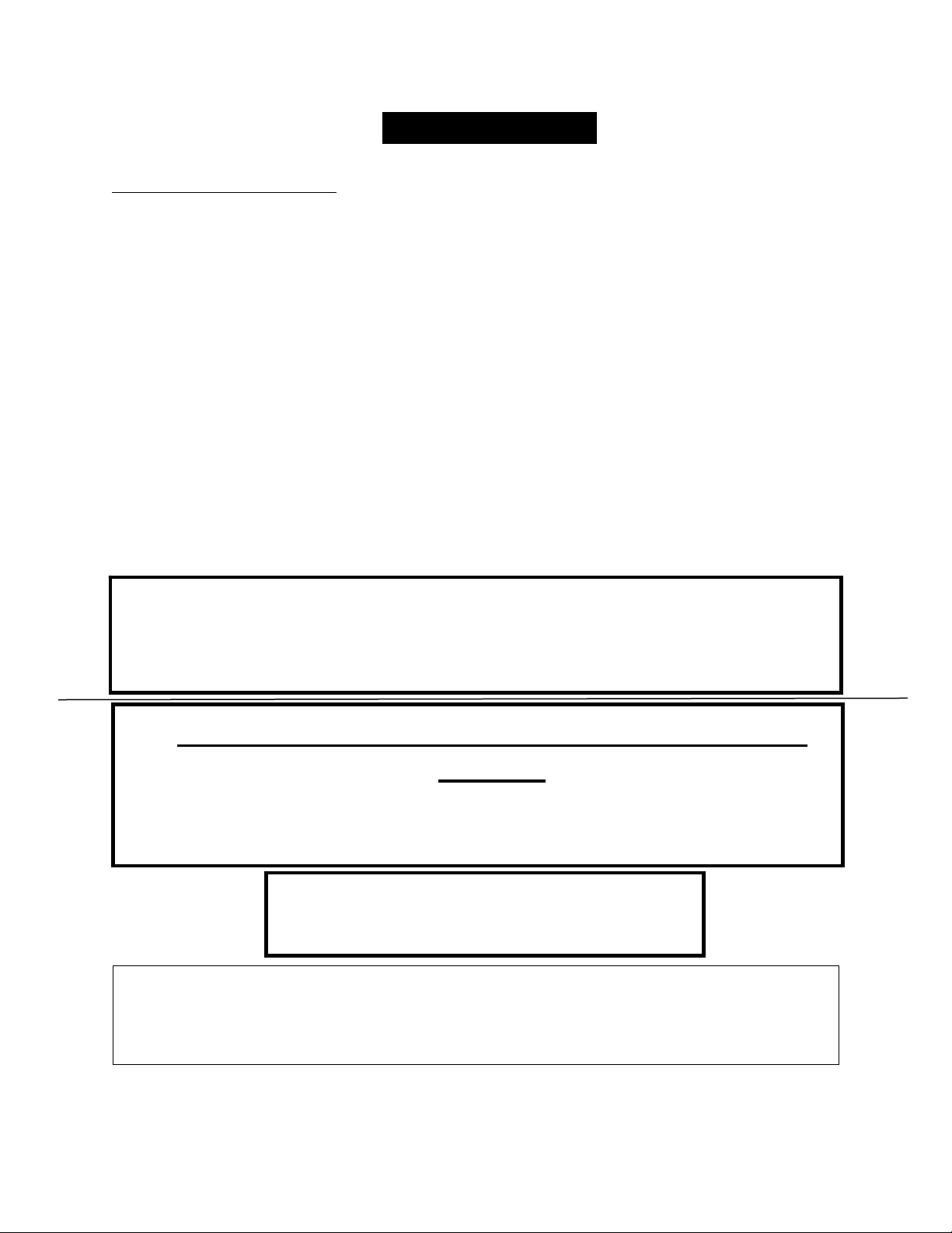
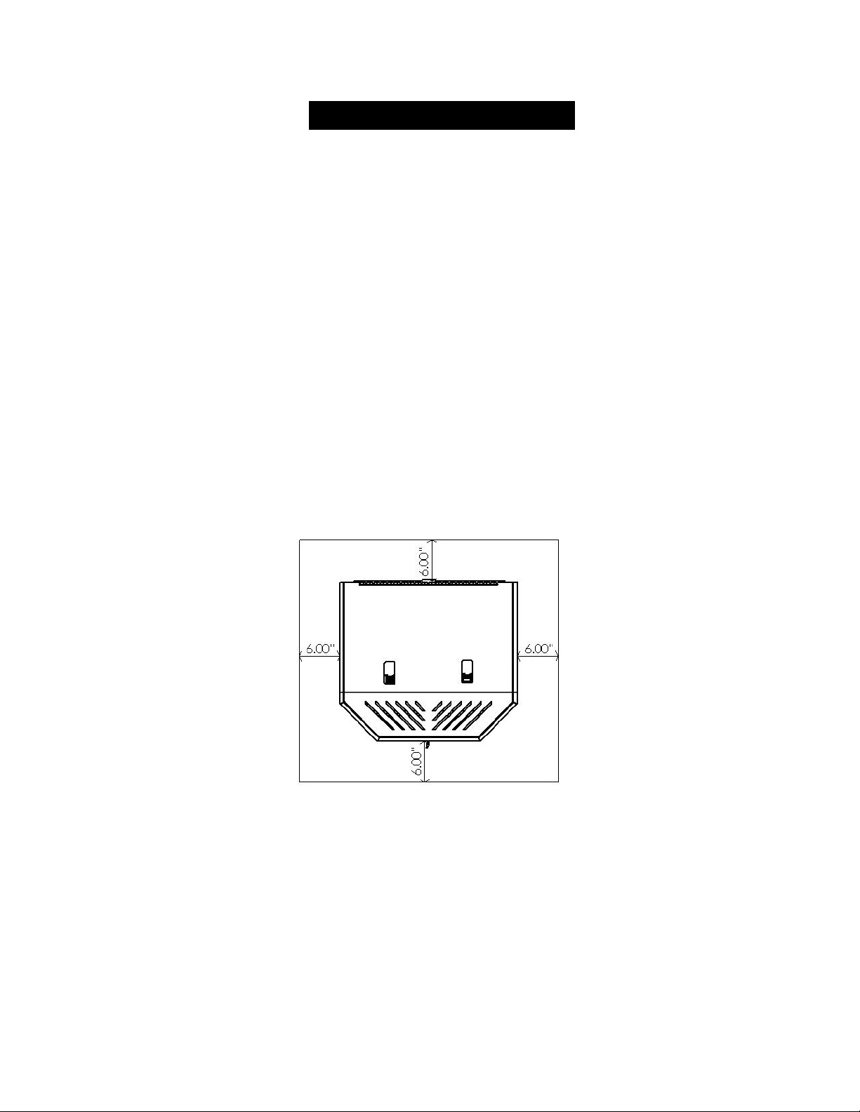
FLOOR PROTECTION
The 25-CBEP requires a non-combustible floor protector if the stove is to be
installed on a combustible floor. If the floor the stove is be installed on is
already non-combustible (i.e. a concrete floor in a basement), no floor
protection is needed (although a decorative floor protector can still be used for
aesthetic reasons).
When using any floor protector, consider that this stove is not only heavy but
will induce heating and cooling cycles on the floor protector which can damage
tile and loosen mortar and grout joints.
The floor protector should be UL approved or equivalent (ULC if Canada) and
must only be noncombustible. Since the majority of the radiant heat from this
unit is projected forward, the floor protector only serves to keep ashes and
sparks from landing on combustible flooring near the unit. A hearth rug is
NOT an approved substitute for a proper hearth extension pad.
U.S.A.-The floor protector must extend at least 6 in. (152.4 mm) from the front,
sides and rear of the 25-CBEP, as shown in the diagram below:
In the USA, it is not required that the non-combustible floor protector extends
beneath the venting system, but is highly recommended.
In Canada, it is required that the non-combustible floor protector is underneath
and extends 2 in. (50.8 mm.) on either side of any horizontal venting runs
AND/OR is directly underneath any vertical venting pipe. Canada requires
450mm floor protection in front of unit, and 200mm on sides & rear of unit.

17
IMPORTANT! READ AND FOLLOW ALL INSTALLATION AND MAINTENANCE INSTRUCTIONS, INCLUDING
CLEANING THE UNIT AS SPECIFIED, AND REPLACING GASKETS ANNUALLY, AND PARTS AS NEEDED.
ENGLAND’S STOVE WORKS IS NOT RESPONSIBLE FOR ANY DAMAGE OR INJURY INCURRED DUE TO NEGLECT, OR
DUE TO UNSAFE INSTALLATION OR USAGE OF THIS PRODUCT. CALL TECHNICAL SUPPORT WITH QUESTIONS.
DAILY OPERATION
Getting Started
Check to see that the hopper is clean and free from foreign materials. Be sure
to connect this unit to a working outlet; we recommend using a surge protector
to help protect the electronic components from damage.
BEFORE your first fire, dry run your unit (no pellet fuel in the hopper) for
twenty minutes; pressing the “ON” button with the unit plugged in will initiate
the dry run.
o Once the “ON” button is pressed, you should immediately hear the
exhaust blower start and operate continuously.
o After about three to five minutes, look for the red glow of the igniter in
the igniter port of the burn pot to be certain it is operating normally.
o Hold the hopper lid switch (See “Illustrated Parts Diagram” for your unit
at the rear of this manual) down with your finger and check to see that
the auger is turning. Release the hopper lid switch and be certain that the
auger stops turning. DO NOT PUT YOUR FINGERS IN THE
HOPPER OR NEAR THE ROTATING AUGER.
After about twenty minutes, the control board should display “E-2” in the two
display windows (More information on Error Codes can be found in the Error
Code section of this manual).
At this point, the dry run is complete and your pellet heating appliance is ready
for normal operation.
Lighting a Fire
In order for this stove to operate, the hopper must first be filled with pellet fuel.
Lift the hopper lid using the flush-mount handle and pour the pellet fuel directly
into the hopper.
We recommend using only pellets manufactured by PFI Certified
facilities, since pellets bearing the PFI stamp of approval will be low
in ash and moisture, high in BTU’s, and uniform in size and quality.

18
IMPORTANT! READ AND FOLLOW ALL INSTALLATION AND MAINTENANCE INSTRUCTIONS, INCLUDING
CLEANING THE UNIT AS SPECIFIED, AND REPLACING GASKETS ANNUALLY, AND PARTS AS NEEDED.
ENGLAND’S STOVE WORKS IS NOT RESPONSIBLE FOR ANY DAMAGE OR INJURY INCURRED DUE TO NEGLECT, OR
DUE TO UNSAFE INSTALLATION OR USAGE OF THIS PRODUCT. CALL TECHNICAL SUPPORT WITH QUESTIONS.
The 25-CBEP will perform equally well using softwood and hardwood pellets,
and although the ash may differ slightly in appearance or texture, both types of
pellets will burn cleanly and efficiently in this stove.
The 25-CBEP is equipped with an automatic pellet ignition system; the only
user input required to light the stove is a simple press of the “On” button.
Shortly after pressing the “On” button, the letters “S U” will appear in the heat
range and blower speed windows of the control board. This indicates the stove
has entered the start-up sequence and is operating normally.
The fuel feed rate and combustion air during start-up is determined by the
control board, so the stove may be started on any heat range, although we
recommend starting the stove on Heat Range 5, to help ensure a strong fire is
initiated.
After approximately fifteen minutes, the fire should be burning brightly and the
“S U” should disappear from the control board. At this point, the stove has
begun normal operation and the display windows on the control board will
remain empty, unless the Heat Range or Blower Speed is adjusted.
Daily Operation Notes
Only high quality, ¼” (.25 in.) diameter wood pellets, should be used in this
stove. Using low grade wood pellets with high ash content can cause the
burnpot to fill with ash at a more rapid pace and can cause intervals between
periodic maintenance to become significantly shorter. Please read the
“Maintenance” section of this manual thoroughly to understand how fuel
selection affects stove operation, maintenance and cleaning.
Variation in the flame height is normal; not all wood fuel is uniform in size,
which can affect the way pellets are fed into the burnpot. Although the flame
height may increase and decrease during operation, the temperature of the
exhaust gas remains relatively constant and there is no loss of efficiency.
CAUTION
NEVER USE GASOLINE, GASOLINE-TYPE LANTERN FUEL, KEROSENE,
CHARCOAL LIGHTER FLUID, OR SIMILAR LIQUIDS TO START OR “FRESHEN UP”
A FIRE IN THIS HEATER. KEEP ALL SUCH LIQUIDS WELL AWAY FROM THE
HEATER WHILE IN USE. ADDITIONALLY, NEVER APPLY FIRE-STARTER TO ANY
HOT SURFACE OR EMBERS IN THE STOVE.

19
IMPORTANT! READ AND FOLLOW ALL INSTALLATION AND MAINTENANCE INSTRUCTIONS, INCLUDING
CLEANING THE UNIT AS SPECIFIED, AND REPLACING GASKETS ANNUALLY, AND PARTS AS NEEDED.
ENGLAND’S STOVE WORKS IS NOT RESPONSIBLE FOR ANY DAMAGE OR INJURY INCURRED DUE TO NEGLECT, OR
DUE TO UNSAFE INSTALLATION OR USAGE OF THIS PRODUCT. CALL TECHNICAL SUPPORT WITH QUESTIONS.
CONTROL BOARD SETTINGS
The control board on this stove allows the user to adjust the heat output and
convection blower speed, turn the unit on and off, and test components for function
(more on diagnostic mode later).
The lower buttons on the control board (Low Fuel Feed, Low Burn Air, and Air
on Temp) are not meant to be adjusted during normal operation of the unit.
These buttons are factory preset and should not be adjusted by the user.
To energize the unit and initiate a fire, press the “On” button. The LED above
the button should turn green and the control board should display “S U” shortly
after pressing the button.
To shut the unit down, press the “Off” button. The LED above the button
should turn red and the board should display “S d” shortly after pressing the
button. This initiates the shut down sequence, and the stove will remain in shut
down mode until it has cooled down.
To increase the heat output of the stove, press the “Up” heat range button. The
number in the heat range display window will increase, signifying that the
control board is now adjusting the heat output to your desired level. The blower
speed will increase the same amount as the heat range, because the stove is
designed to operate with the blower speed greater than or equal to the heat
range. Pressing the “Down” arrow will decrease the heat range and blower
speed.
To increase the blower speed without increasing the heat range, press the
Blower Speed “Up” arrow until the desired blower speed is shown in the
display window. Pressing the “Down” arrow will decrease the blower speed;
however the control board will not allow the blower speed to be set lower than
the heat range.
20
IMPORTANT! READ AND FOLLOW ALL INSTALLATION AND MAINTENANCE INSTRUCTIONS, INCLUDING
CLEANING THE UNIT AS SPECIFIED, AND REPLACING GASKETS ANNUALLY, AND PARTS AS NEEDED.
ENGLAND’S STOVE WORKS IS NOT RESPONSIBLE FOR ANY DAMAGE OR INJURY INCURRED DUE TO NEGLECT, OR
DUE TO UNSAFE INSTALLATION OR USAGE OF THIS PRODUCT. CALL TECHNICAL SUPPORT WITH QUESTIONS.
ERROR CODES
Error codes, or “E-Codes,” are alphanumeric codes that will appear in the Heat
Range and Blower Speed windows of the Control Board if the unit experiences an
abnormal condition. Error codes are the control board’s way of telling the user that
something isn’t operating correctly within the stove, and that the unit should be
carefully inspected before reigniting. See the “Trouble-Shooting Guide,” page 37,
for additional information on error codes.
E-0
When this is displayed in the control board windows (typically when
restarting after an “E-Code” shutdown), it means there are currently no
errors and the stove will begin normal operation.
E-1
This error code is not used on this stove. If it is displayed in the control
board windows, please contact Technical Support and they will diagnose
the cause of the false code.
E-2
When this code is displayed in the control board window it indicates a
failure to light. Although the stove may have ignited the pellets, the
control board did not register a high enough temperature to determine the
fire was lit. If a fire was ignited, wait for the unit to cool, clean the
burnpot and restart the unit.
E-3
This error code indicates the preset maximum allowable exhaust
temperature was exceeded. Commonly referred to as “Over-Firing,” the
E-3 code means something in the stove is causing the exhaust gas to be
hotter than expected.
E-4
This code is displayed based on a drop in the exhaust temperature. This
code means the fire or “proof of flame” has been lost. It usually results
from the hopper being empty.
If an error code continues to display, if the error code seems
unexplainable, or if you have any other questions about
error codes and what they mean, please contact Technical
Support at (800) 245-6489.
21
IMPORTANT! READ AND FOLLOW ALL INSTALLATION AND MAINTENANCE INSTRUCTIONS, INCLUDING
CLEANING THE UNIT AS SPECIFIED, AND REPLACING GASKETS ANNUALLY, AND PARTS AS NEEDED.
ENGLAND’S STOVE WORKS IS NOT RESPONSIBLE FOR ANY DAMAGE OR INJURY INCURRED DUE TO NEGLECT, OR
DUE TO UNSAFE INSTALLATION OR USAGE OF THIS PRODUCT. CALL TECHNICAL SUPPORT WITH QUESTIONS.
POWER FAILURE
If the power to the unit is interrupted for approximately three minutes or
less, the unit will resume operation when power is restored according to
the following table:
Unit’s State Before Power Loss State When Power Returns
ON Start-Up
Start-Up Start-Up
Shut-Down Shut-Down
OFF OFF
If the power is interrupted for more than (approximately) three
minutes, the unit will be “OFF” when power returns.
IMPORTANT – Do NOT open the hopper lid or the door to
the unit during power outage. Open the closest outside door and
a window to reduce the chance of any combustion byproducts
entering the home.
Wait for the power to be restored and then press the “ON”
button to restart the unit, if necessary.
Caution – Shock Hazard
Press the “Off” button and let the appliance completely cool BEFORE
unplugging the appliance and beginning any maintenance or component
replacement.
Risk of shock if a
pp
liance is not un
p
lu
gg
ed before service.
22
IMPORTANT! READ AND FOLLOW ALL INSTALLATION AND MAINTENANCE INSTRUCTIONS, INCLUDING
CLEANING THE UNIT AS SPECIFIED, AND REPLACING GASKETS ANNUALLY, AND PARTS AS NEEDED.
ENGLAND’S STOVE WORKS IS NOT RESPONSIBLE FOR ANY DAMAGE OR INJURY INCURRED DUE TO NEGLECT, OR
DUE TO UNSAFE INSTALLATION OR USAGE OF THIS PRODUCT. CALL TECHNICAL SUPPORT WITH QUESTIONS.
THERMOSTAT OPERATION
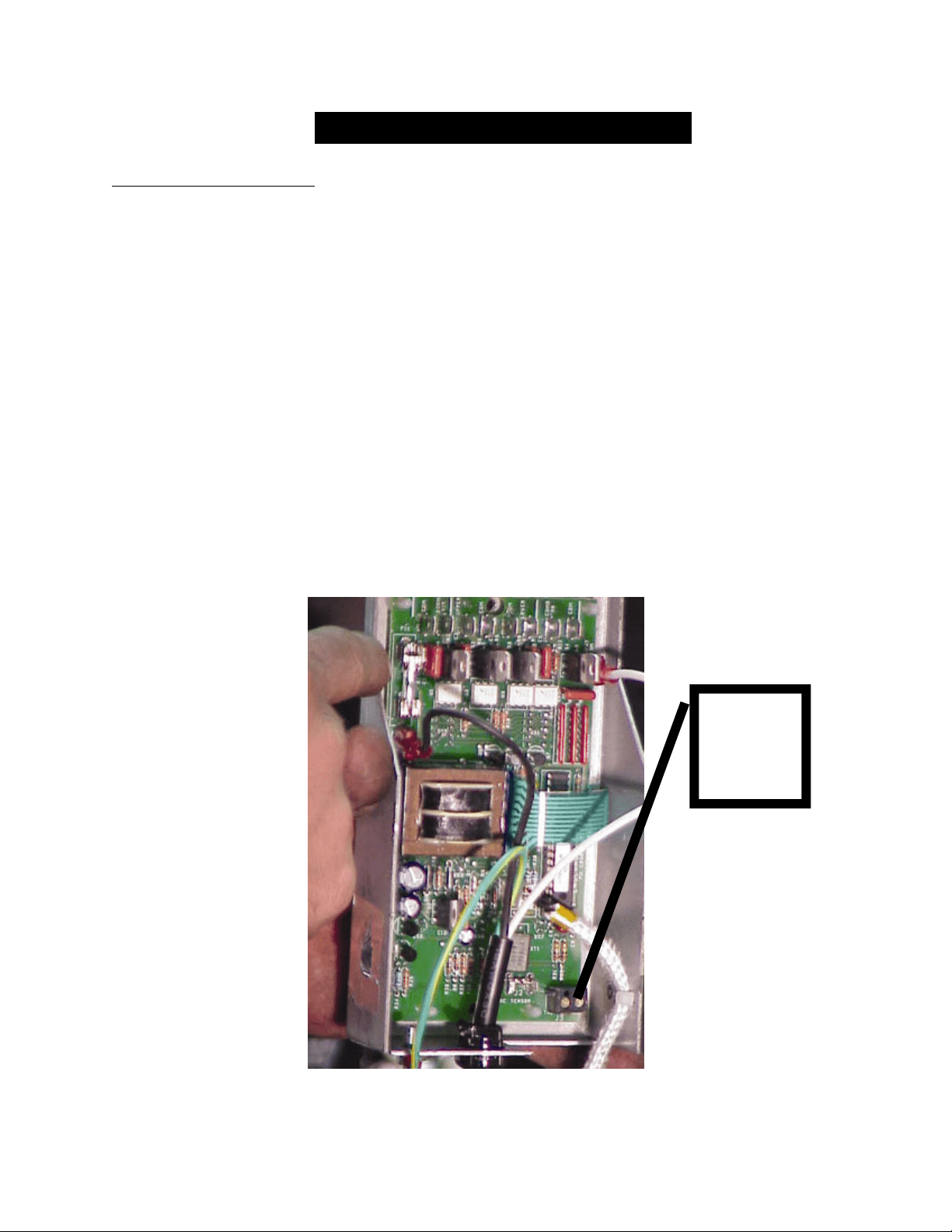
Thermostat Installation
1. Unplug the unit and remove the back panel of the stove.
2. Locate the thermostat connect block, labeled J18, on the rear of the control
board, near the bottom (See image below and page 44 of this manual for a
control board diagram). It will have a small wire “jumper” installed in it
from the factory. This jumper bypasses the thermostat and should be saved.
3. Loosen the two screws using a small slotted “jewelers” screwdriver and
remove the “jumper.”
4. Insert the two thermostat wires in place of the “jumper” and retighten the
screws.
5. Reinstall the back panel and mount the thermostat; the control board
automatically reads the thermostat and your stove is now ready for
thermostat operation.
Connect
thermostat
wires here
(J18)

23
IMPORTANT! READ AND FOLLOW ALL INSTALLATION AND MAINTENANCE INSTRUCTIONS, INCLUDING
CLEANING THE UNIT AS SPECIFIED, AND REPLACING GASKETS ANNUALLY, AND PARTS AS NEEDED.
ENGLAND’S STOVE WORKS IS NOT RESPONSIBLE FOR ANY DAMAGE OR INJURY INCURRED DUE TO NEGLECT, OR
DUE TO UNSAFE INSTALLATION OR USAGE OF THIS PRODUCT. CALL TECHNICAL SUPPORT WITH QUESTIONS.
THERMOSTAT OPERATION
Thermostat Operation Details
The 25-CBEP was designed to operate equally well in both manual and thermostat mode.
While using the control board for heating control gives the user control over the heat
output of the stove, the thermostat allows the stove to “start-up” and “shutdown”
independently, which will help maintain your house at a more constant temperature and
save pellet fuel.
The 25-CBEP can be connected to either a wall thermostat (Part # PU-DTSTAT) or
wireless remote thermostat (Part # AC-3003). Although either thermostat will operate
the stove properly, we highly recommend the wireless thermostat for the convenience of
starting your pellet stove from anywhere in the house.
THERMOSTAT OPERATION: This stove is equipped with a unique, new feature that
allows two options for thermostatic operation: The stove comes from the factory pre-
programmed in “On/Off mode,” which turns the stove on and off when the call for heat
comes or leaves, like a furnace. The second, or “High/Low mode,” burns at whichever
heat range you set the stove at until the call for heat leaves, at which point the stove goes
to the Low heat range setting.
To set the stove in the “High/Low mode,” unplug the unit and plug it back in, then press
and release both down arrows; H L appears in the heat range and blower speed windows.
The unit is now in “High/Low mode.” (Note: Repeat this to change back to “On/Off
mode;” a 0 0 will appear in the heat range and blower speed windows). Using a
thermostat in On/Off mode may shorten the life of your stove’s igniter.
Please note: Certain units may not respond to this; if your unit does not respond in this
manner please contact Technical Support at (800) 245-6489.
Remember to locate the thermostat near the stove in a central location; putting the
thermostat in a distant room can cause the stove to overheat the room it’s located in
because the thermostat will only sense the temperature of the room in which it is
installed.
Although all heat range and blower speed settings are available in thermostat mode, the
two settings specifically designed for thermostat mode are heat ranges 3 and 8.
o Heat range 3 is intended for thermostat operation under normal operating
conditions.
o Heat range 8 is ideal for thermostat operation in large or poorly insulated homes.
24
IMPORTANT! READ AND FOLLOW ALL INSTALLATION AND MAINTENANCE INSTRUCTIONS, INCLUDING
CLEANING THE UNIT AS SPECIFIED, AND REPLACING GASKETS ANNUALLY, AND PARTS AS NEEDED.
ENGLAND’S STOVE WORKS IS NOT RESPONSIBLE FOR ANY DAMAGE OR INJURY INCURRED DUE TO NEGLECT, OR
DUE TO UNSAFE INSTALLATION OR USAGE OF THIS PRODUCT. CALL TECHNICAL SUPPORT WITH QUESTIONS.
DAILY MAINTENANCE
Important Notes
As with any maintenance concerning this unit, be sure the unit is “OFF” and
has completed the Shut-Down cycle BEFORE beginning.
Be aware that metal parts in the firebox can remain HOT long after the fire
has gone out and EVEN after the Shut-Down cycle is complete. Always use
extreme caution when handling potentially hot stove parts, even if you think
they should be cold.
Ashes should only be removed when the stove has been shut-down and has
been allowed to cool thoroughly. Hot embers can remain under ashes long
after the fire has gone out, so always be extra careful when handling any
ashes from this (or any) stove.
Store ashes in a metal container with a tight fitting lid, and only place this
container on a non-combustible surface.
Different pellets will generate varying amounts of ash and burnpot deposits.
Carefully monitor the ash build up in the stove when first operating the unit,
as well as whenever a different brand of pellets is burned.
While the amount of ash generated by this unit is not excessive compared to
a traditional log-burning woodstove, keeping the unit clean and free of ash is
ESSENTIAL for peak performance and maximum efficiency. Ash build-up
hampers airflow, reduces efficiency, and can cause a smoke back.
England’s Stove Works
® is not responsible for any damages incurred due to
a poorly maintained and/or dirty stove. This pellet stove is a highly efficient
machine and, as such, requires sufficient maintenance to keep it operating at
its peak.
Disposal of Ashes – Ashes should be placed in a metal container with a tight
fitting lid. The closed container of ashes should be placed on a noncombustible
floor or on the ground, well away from all combustible materials, pending final
disposal. If the ashes are disposed of by burial in soil or otherwise locally
dispersed, they should be retained in the closed container until all cinders have
been thoroughly cooled.
*Failure to
p
ro
p
erl
y
clean
y
our stove can cause
p
oor
p
er
f
ormance and
p
ossibl
y
a burn back!*

25
IMPORTANT! READ AND FOLLOW ALL INSTALLATION AND MAINTENANCE INSTRUCTIONS, INCLUDING
CLEANING THE UNIT AS SPECIFIED, AND REPLACING GASKETS ANNUALLY, AND PARTS AS NEEDED.
ENGLAND’S STOVE WORKS IS NOT RESPONSIBLE FOR ANY DAMAGE OR INJURY INCURRED DUE TO NEGLECT, OR
DUE TO UNSAFE INSTALLATION OR USAGE OF THIS PRODUCT. CALL TECHNICAL SUPPORT WITH QUESTIONS.
DAILY MAINTENANCE
Ash Removal and Disposal
Press the “Off” button and allow the stove to complete the shut-down cycle
and cool completely.
Because of the open design of the firebox, the majority of the ash will
already be in the bottom of the stove. Open the main door of the stove and
use an old paint brush or putty knife to move ash from around the burnpot
into the floor of the stove below.
Use a long handled screwdriver or putty knife to remove any deposits left in
the burnpot, being careful to remove them from the burnpot and not allow
them to filter down into the cradle area. Excessive ash build-up in the cradle
can cause poor stove performance (See “Cleaning the Burnpot” page 26).
Remove the ashes from the bottom of the stove with a scoop, or by using an
ash (utility type) vacuum such as our Part Number AC-SV. Follow all
appliance directions.
When using a utility type vacuum for ash clean-out, be certain the vacuum is
equipped with a filter capable of preventing fine ash particles from being
blown into the room. Similarly, always be certain the stove is completely
cool and that ALL ashes are cool before vacuuming.
Dump the ashes into a metal container (as described above) and store them
on a non-combustible surface to allow any embers to cool before disposal.
The stove is now ready to resume normal operation.

26
IMPORTANT! READ AND FOLLOW ALL INSTALLATION AND MAINTENANCE INSTRUCTIONS, INCLUDING
CLEANING THE UNIT AS SPECIFIED, AND REPLACING GASKETS ANNUALLY, AND PARTS AS NEEDED.
ENGLAND’S STOVE WORKS IS NOT RESPONSIBLE FOR ANY DAMAGE OR INJURY INCURRED DUE TO NEGLECT, OR
DUE TO UNSAFE INSTALLATION OR USAGE OF THIS PRODUCT. CALL TECHNICAL SUPPORT WITH QUESTIONS.
DAILY MAINTENANCE
Cleaning the Burnpot
Along with removing ashes from the stove, cleaning the burnpot is the other
essential part of daily maintenance that will keep the stove operating at its peak.
Pellets contain varying amounts of impurities and fusible material that will
accumulate in the burnpot over time. Some pellets will contain much higher
amounts of these fusible impurities, therefore extra vigilance may be required to
maintain a clean burnpot. Allowing impurities to build up in the burnpot can
restrict the air-flow to the fire, resulting in a dirty, inefficient burn.
Instructions
Always allow the stove to finish the shut-down cycle and cool completely
before performing any maintenance inside the firebox.
Open the main door of the stove and remove the burnpot by lifting it straight
up and out of the cradle. WARNING – The burnpot can remain HOT long
after the fire has gone out, so wear protective gloves whenever handling a
potentially hot burnpot.
Once the burnpot is out of the stove, use a long handled screwdriver or putty
knife, as previously mentioned, to remove any deposits from the inside of
the burnpot.
Be certain all air orifices are clear and unrestricted by fusible ash matter; a
fine tipped screwdriver or scratch awl can be useful in removing stubborn
matter from these orifices.
Remove any ash material from the bottom of the cradle and brush any ash
from the top of the cradle into the floor of the stove below. Keeping the top
of cradle free of ash is crucial in allowing the burnpot to make a positive air-
tight seal with the top of the cradle.
Insert the burnpot back into the cradle using the reverse of the procedure
detailed above.

27
IMPORTANT! READ AND FOLLOW ALL INSTALLATION AND MAINTENANCE INSTRUCTIONS, INCLUDING
CLEANING THE UNIT AS SPECIFIED, AND REPLACING GASKETS ANNUALLY, AND PARTS AS NEEDED.
ENGLAND’S STOVE WORKS IS NOT RESPONSIBLE FOR ANY DAMAGE OR INJURY INCURRED DUE TO NEGLECT, OR
DUE TO UNSAFE INSTALLATION OR USAGE OF THIS PRODUCT. CALL TECHNICAL SUPPORT WITH QUESTIONS.
BIWEEKLY MAINTENANCE
Important Notes
As with any maintenance concerning this unit, be sure the unit is “OFF,” has
completed the Shut-Down cycle, and is completely cool BEFORE
beginning.
Be aware that metal parts in the firebox can remain HOT long after the fire
has gone out and EVEN after the Shut-Down cycle is complete. Always use
extreme caution when handling potentially hot stove parts, even if you think
they should be cold.
Biweekly maintenance should include the steps listed in this section AS
WELL AS the steps listed in the previous “Daily Maintenance” section.
Burning some brands of pellets may lead to increased ash build-up behind
the exhaust cover and in the igniter tube. Diligent maintenance in the first
year will help you understand the location of ash build-up as well as the
necessary intervals between cleanings.
Although not specifically listed in this section, the gaskets and latches on the
main door should always be inspected to ensure a proper seal is being made.
As previously mentioned, an airtight seal at all stove openings is crucial to
proper operation.
When using a utility type vacuum for ash clean-out during biweekly
maintenance, be certain the vacuum is equipped with a filter capable of
preventing fine ash particles from being blown into the room. Similarly,
always be certain the stove is completely cool and that ALL ashes are cool
before vacuuming.
Clean-out tees and other low spots in venting systems are areas prone to fly
ash accumulation. Be certain these areas are inspected frequently for
excessive ash accumulation.

28
IMPORTANT! READ AND FOLLOW ALL INSTALLATION AND MAINTENANCE INSTRUCTIONS, INCLUDING
CLEANING THE UNIT AS SPECIFIED, AND REPLACING GASKETS ANNUALLY, AND PARTS AS NEEDED.
ENGLAND’S STOVE WORKS IS NOT RESPONSIBLE FOR ANY DAMAGE OR INJURY INCURRED DUE TO NEGLECT, OR
DUE TO UNSAFE INSTALLATION OR USAGE OF THIS PRODUCT. CALL TECHNICAL SUPPORT WITH QUESTIONS.
BIWEEKLY MAINTENANCE
Exhaust Cover Removal & Cleaning
Fly ash will accumulate behind the exhaust cover and in other non-visible
areas.
The firebox exhaust cover is a one-piece design, held in place with two (2)
5/16” screws.
Remove the exhaust cover plate by first removing the two (2) 5/16” screws,
then lifting the entire exhaust cover from the stove.
o Remember, always use extreme caution when handling potentially hot
stove parts, even if you think they should be cold.
When the exhaust cover is out of the stove, the area where fly-ash
accumulates on the firebox shelf will be clearly seen.
The use of a utility (or ash) vacuum such as our Part Number AC-SV is
highly recommended.
Exhaust Chamber Cleaning
The exhaust chamber of the stove (seen when the cover is removed) was
intentionally designed as an ash accumulation area. Allowing ash to accumulate
here prevents excess ash build-up in the combustion blower and the venting
system.
Instructions
BEFORE vacuuming the chamber out, observe the type and quantity of ash
build-up. The ash deposited in the exhaust chamber should be light, fluffy,
grey or white in color, and should be no higher than half way up the clean-
out port.
o If the ash is dark brown or black, it is generally evidence of
incomplete pellet combustion.
o Do NOT allow the ash to accumulate very high in this area;
significant ash accumulation in this area can “choke” the combustion
blower and cause poor stove performance.

29
IMPORTANT! READ AND FOLLOW ALL INSTALLATION AND MAINTENANCE INSTRUCTIONS, INCLUDING
CLEANING THE UNIT AS SPECIFIED, AND REPLACING GASKETS ANNUALLY, AND PARTS AS NEEDED.
ENGLAND’S STOVE WORKS IS NOT RESPONSIBLE FOR ANY DAMAGE OR INJURY INCURRED DUE TO NEGLECT, OR
DUE TO UNSAFE INSTALLATION OR USAGE OF THIS PRODUCT. CALL TECHNICAL SUPPORT WITH QUESTIONS.
Using a utility type vacuum cleaner, as previously mentioned in this manual,
vacuum the fly ash out of the exhaust chamber. A short piece of hose can be
attached to the end of the utility vacuum line and can be useful in accessing
hard-to-reach areas.
After removing all fly-ash from behind the cover and exhaust chamber area,
reinsert the cover into the stove, using the two (2) 5/16” screws that were
previously removed.
Be certain to tighten the screws down to sufficiently seal, but do not over-
tighten them, as it possible to damage the screws.
Caution
Thisunitismeanttooperateonlywiththemainviewingdoorclosed.Smoke
spillageandaninefficient,lazyburnwillresultfromattemptingtooperatethe
stovewiththedooropen.
Inaddition,usingfuelotherthanwoodpelletscancreateanunsafesituationand
canalsogenerateexcesscarbon
monoxide.Carbonmonoxideisanodorless,
colorlessgaswhichcanbedeadly.
BurnONLYwoodpellets.
CarbonMonoxideDetector
England’sStoveWorks,Inc.highlyrecommendstheuseofacarbonmonoxide
detectorintheproximityofthestoveandoneperfloorofthehome.
Acertainamountofcarbonmonoxideisproducedwithinthestoveasaby‐productofcombustion.
AllexhaustventconnectionsmustbesealedwithRTVSiliconetoassureatightseal.Anyleaksinto
aconfinedareacausedbyfaultyinstallationorimproperoperationofthestovecouldproduce
dizziness,nauseaandinextremecases,death.TheCOconcentrationduringtestingwasfoundto
be0.017g/min.

30
IMPORTANT! READ AND FOLLOW ALL INSTALLATION AND MAINTENANCE INSTRUCTIONS, INCLUDING
CLEANING THE UNIT AS SPECIFIED, AND REPLACING GASKETS ANNUALLY, AND PARTS AS NEEDED.
ENGLAND’S STOVE WORKS IS NOT RESPONSIBLE FOR ANY DAMAGE OR INJURY INCURRED DUE TO NEGLECT, OR
DUE TO UNSAFE INSTALLATION OR USAGE OF THIS PRODUCT. CALL TECHNICAL SUPPORT WITH QUESTIONS.
MONTHLY MAINTENANCE
Important Notes
As with any maintenance concerning this unit, be sure the unit is “OFF,” has
completed the Shut-Down cycle, and is completely cool BEFORE
beginning.
Be aware that metal parts in the firebox can remain HOT long after the fire
has gone out and EVEN after the Shut-Down cycle is complete. Always use
extreme caution when handling potentially hot stove parts, even if you think
they should be cold.
Monthly maintenance should include the steps listed in this section AS
WELL AS the steps listed in the “Daily Maintenance” and “Biweekly
Maintenance” sections.
Intervals between monthly cleanings will depend on the duration that the
stove is burning on a daily basis. A stove which is operated continuously
will need more frequent monthly cleanings than a stove which is used
periodically as supplemental heat.
A good rule of thumb for monthly maintenance is that it should be done each
time an entire ton of pellets is burned OR once per month, whichever comes
first.
If excess ash accumulation is found in the exhaust chamber or venting
system during monthly maintenance, the interval between cleanings should
be reduced to eliminate the possibility of poor stove performance due to ash
accumulation.

31
IMPORTANT! READ AND FOLLOW ALL INSTALLATION AND MAINTENANCE INSTRUCTIONS, INCLUDING
CLEANING THE UNIT AS SPECIFIED, AND REPLACING GASKETS ANNUALLY, AND PARTS AS NEEDED.
ENGLAND’S STOVE WORKS IS NOT RESPONSIBLE FOR ANY DAMAGE OR INJURY INCURRED DUE TO NEGLECT, OR
DUE TO UNSAFE INSTALLATION OR USAGE OF THIS PRODUCT. CALL TECHNICAL SUPPORT WITH QUESTIONS.
MONTHLY MAINTENANCE
Venting Pipe Cleaning
Low spots and direction changes in the venting system (such as tees and
elbows) are areas for potential fly-ash accumulation. INSPECT these areas
diligently to keep the venting system in safe operating condition.
Depending on the specific type of venting system your stove is connected to,
it may be possible to remove the clean-out tee cover and simply run a pipe
brush up the pipe to remove any fly-ash accumulation. Brushes specifically
made for cleaning pellet pipe are available at the retailer where you bought
this stove, as well as at most hearth product dealers.
Horizontal runs of pipe, such as from the exhaust connection on the stove to
the vertical transition, will accumulate fly ash and should be inspected
carefully and brushed clean.
Check the termination cap to be certain it is not clogged or restricted by any
fly-ash accumulation.
After thoroughly cleaning the venting system, reseal any disassembled
seams with high temperature silicone (Part # AC-RTV3) if applicable to
your venting system.
Inspect seams that were not disassembled to be certain a smoke-tight seal is
still being made.
After prolonged use, leaks in the venting system can usually be found by
searching for fly-ash deposits on the outside of the pipe. Carefully check for
leaks in the venting system and seal them accordingly.
Although most pellet venting systems are designed to last a lifetime, pellet
fly-ash can be corrosive under certain conditions. When cleaning your
venting system, examine the pipe carefully for any signs of deterioration and
replace sections that show excessive wear. It is unlikely that this will ever
be a concern, but maintaining your venting system in safe operating
condition is crucial to safe stove operation.
32
IMPORTANT! READ AND FOLLOW ALL INSTALLATION AND MAINTENANCE INSTRUCTIONS, INCLUDING
CLEANING THE UNIT AS SPECIFIED, AND REPLACING GASKETS ANNUALLY, AND PARTS AS NEEDED.
ENGLAND’S STOVE WORKS IS NOT RESPONSIBLE FOR ANY DAMAGE OR INJURY INCURRED DUE TO NEGLECT, OR
DUE TO UNSAFE INSTALLATION OR USAGE OF THIS PRODUCT. CALL TECHNICAL SUPPORT WITH QUESTIONS.
YEARLY MAINTENANCE
Important Notes
As with any maintenance concerning this unit, be sure the unit is “OFF,” has
completed the Shut-Down cycle, and is completely cool BEFORE
beginning.
Be aware that metal parts in the firebox can remain HOT long after the fire
has gone out and EVEN after the Shut-Down cycle is complete. Always use
extreme caution when handling potentially hot stove parts, even if you think
they should be cold.
Yearly (or end of season) maintenance should include the steps listed in this
section AS WELL AS the steps listed in the “Daily Maintenance,”
“Biweekly Maintenance” and “Monthly Maintenance” sections of this
manual.
Yearly maintenance should be performed at the end of the burning season.
Leaving ash and other build-up in the stove during the non-heating months
can lead to premature metal degradation in the stove and venting system.
Using extra attention to detail and being certain to be very thorough in the
end of season cleaning will help increase the operating life of the stove and
venting system.
Caution – Shock Hazard
Press the “Off” button and let the appliance completely cool BEFORE
unplugging the appliance and beginning any maintenance or component
replacement.
Risk of shock if appliance is not unplugged before service.
Soot and Fly Ash: Formation and Need for Removal
The products of combustion will contain small particles of fly ash. The fly ash
will collect in the exhaust venting system and restrict the flow of the flue gases.
Incomplete combustion, such as that which occurs during startup, shutdown or
incorrect operation of the room heater will lead to some soot formation which
will collect in the exhaust venting system. The exhaust venting system should
be inspected at least once every year to determine if cleaning is necessary.

33
IMPORTANT! READ AND FOLLOW ALL INSTALLATION AND MAINTENANCE INSTRUCTIONS, INCLUDING
CLEANING THE UNIT AS SPECIFIED, AND REPLACING GASKETS ANNUALLY, AND PARTS AS NEEDED.
ENGLAND’S STOVE WORKS IS NOT RESPONSIBLE FOR ANY DAMAGE OR INJURY INCURRED DUE TO NEGLECT, OR
DUE TO UNSAFE INSTALLATION OR USAGE OF THIS PRODUCT. CALL TECHNICAL SUPPORT WITH QUESTIONS.
YEARLY MAINTENANCE
Exhaust Blower Cleaning
Although the exhaust blower and blower housing were designed to minimize ash
build-up, some fly-ash will still accumulate there throughout the burning season.
The amount and type of ash will depend on the type of pellets and venting system,
but generally this accumulation will be mild. If, when cleaning the exhaust
blower, a large accumulation of fly-ash is found, cleaning the exhaust blower and
housing should be performed monthly or bimonthly to prevent this excess buildup.
Instructions
Before beginning the exhaust blower cleaning procedure, be certain the
unit is unplugged and thoroughly cooled down.
To remove the side panel and access the exhaust blower:
o Remove the two 5/16” screws on the rear of the unit that hold the side panel
on, on the side nearest the exhaust blower (the left side when facing the
front of the stove).
o Pull the side panel straight back, supporting it carefully, and pull it away
from the stove; the side panel should slip off of the key slot supports.
o Once the side panel is removed, the exhaust blower will be clearly visible.
Disconnect the venting system from the exhaust blower just enough that you
will be able to remove the exhaust blower from the stove.
Unplug the two wires which connect the stove wiring harness to the exhaust
blower using the quick connect plugs.
Loosen and remove the 5/16” screw, on the top of the exhaust blower output
connection, which holds the thermal sensor to the exhaust blower.
Loosen the five (5) 5/16” self-drilling screws which hold the exhaust blower
to the exhaust blower tube. The lower screws are most easily accessed
through the circular cutouts in the stove body. A 12” socket extension will
likely be necessary to reach all of the screws.
34
IMPORTANT! READ AND FOLLOW ALL INSTALLATION AND MAINTENANCE INSTRUCTIONS, INCLUDING
CLEANING THE UNIT AS SPECIFIED, AND REPLACING GASKETS ANNUALLY, AND PARTS AS NEEDED.
ENGLAND’S STOVE WORKS IS NOT RESPONSIBLE FOR ANY DAMAGE OR INJURY INCURRED DUE TO NEGLECT, OR
DUE TO UNSAFE INSTALLATION OR USAGE OF THIS PRODUCT. CALL TECHNICAL SUPPORT WITH QUESTIONS.
Lift the exhaust blower up and out of the stove. The gasket which seals the
exhaust blower to the exhaust blower tube is fragile, so take extra care when
removing the blower. Even when being careful, though, it is easy to tear this
fragile gasket, and since an airtight seal is crucial here, it is best to replace
this gasket (Part # PU-CBMG) every time the exhaust blower is removed.
With the exhaust blower removed, use a utility (or ash) vacuum to remove
any ash accumulation in the exhaust blower tube.
Use a soft paint brush and carefully remove any ash accumulation from the
inside of the exhaust blower, and from the exhaust blower fan blade.
Inspect the exhaust blower motor for dust accumulation and carefully
remove it, ensuring that all air cooling holes into the motor are open and free
of dust deposits.
Install the blower and side panel in the reverse order as described above.
Remember to check the condition of the exhaust blower gasket AND
remember to reconnect the thermal sensor to the top of the exhaust blower
outlet before reinstalling the side panel.
Side Panel Screws
Side Panel Screws
Rear Panel Screws
Rear Panel Screws

35
IMPORTANT! READ AND FOLLOW ALL INSTALLATION AND MAINTENANCE INSTRUCTIONS, INCLUDING
CLEANING THE UNIT AS SPECIFIED, AND REPLACING GASKETS ANNUALLY, AND PARTS AS NEEDED.
ENGLAND’S STOVE WORKS IS NOT RESPONSIBLE FOR ANY DAMAGE OR INJURY INCURRED DUE TO NEGLECT, OR
DUE TO UNSAFE INSTALLATION OR USAGE OF THIS PRODUCT. CALL TECHNICAL SUPPORT WITH QUESTIONS.
YEARLY MAINTENANCE
Convection Blower Cleaning
As always, be certain the stove is cool and unplugged before servicing any components
within the unit. Since the convection blower does not handle any by-products of
combustion, it does not require serious cleaning like the exhaust blower. However, dust
from the home and other debris in the air can accumulate on the blades of the convection
blower. The convection blower is located on the side of the stove opposite the
combustion blower, and with the side panel removed from the stove, the convection
blower should be visually inspected for any dust build-up. Any dust that has built up on
the fan blades can usually be easily removed with a vacuum or a soft paint brush.
Cleaning Pellet Fines from the Hopper and Auger
Depending on the type and quality of pellets burned in the stove, some accumulation of
pellet fines and dust is possible in the hopper. The lowest part of the auger, near the back
of the stove, is where most fines will accumulate. With the stove off, unplugged, and
with the hopper empty, use a utility vacuum to remove the fines from the auger tube. If
the fines cannot be removed from the top of the hopper:
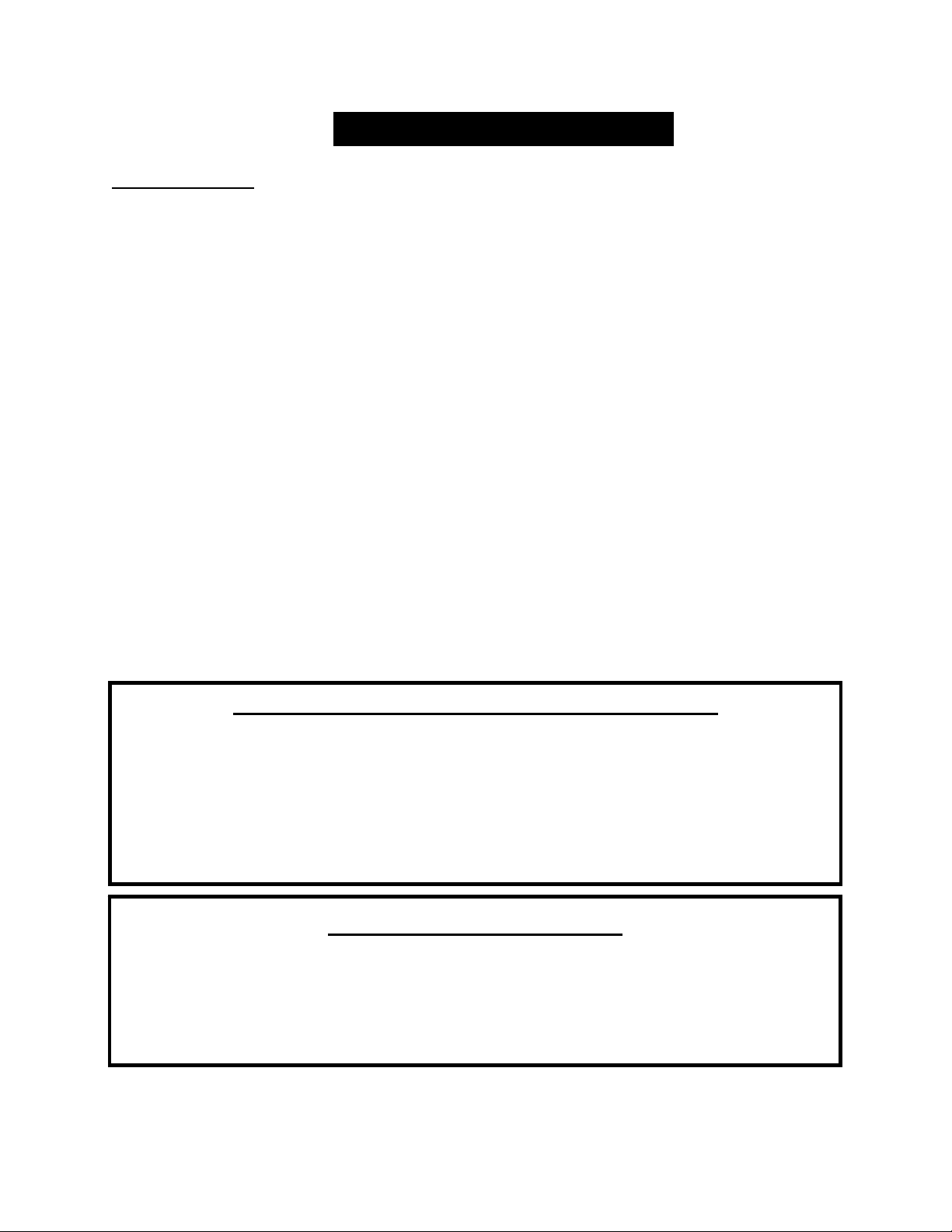
Remove the panels:
o Remove both side panels using the procedure described in the “Exhaust
Blower Cleaning” section, found on page 33 of this manual.
o Next, remove the back panel by removing the four 5/16” screws that hold it
in place and carefully removing it from the stove. See image on pg. 34.
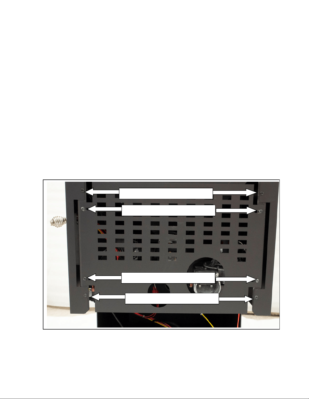
Locate the auger motor assembly at the middle rear of the stove, and once it is
found, find the two set screws on either side of the cast iron mounting collar.
Using a 3/16” allen wrench, loosen the set screw on either side of the auger
mounting collar.
With a utility vacuum in hand, let the auger assembly slide out of the auger tube
just enough so that the vacuum can be used to remove any fines from this area.
Reinstall the auger assembly and tighten the two set screws; reinstall the back
panel and the two side panels, being certain to tighten the eight (8) retaining
screws on the rear of the stove.
Refer to page 39 for an illustration and more information on the auger motor.

36
IMPORTANT! READ AND FOLLOW ALL INSTALLATION AND MAINTENANCE INSTRUCTIONS, INCLUDING
CLEANING THE UNIT AS SPECIFIED, AND REPLACING GASKETS ANNUALLY, AND PARTS AS NEEDED.
ENGLAND’S STOVE WORKS IS NOT RESPONSIBLE FOR ANY DAMAGE OR INJURY INCURRED DUE TO NEGLECT, OR
DUE TO UNSAFE INSTALLATION OR USAGE OF THIS PRODUCT. CALL TECHNICAL SUPPORT WITH QUESTIONS.
YEARLY MAINTENANCE
Checking Gaskets
An airtight seal at the door openings and hopper lid opening is crucial to proper
stove performance. Any air leaks at these areas can not only cause a dirty,
inefficient burn but can also pose a serious safety threat. Because of this, gaskets
should always be maintained in good condition and should be replaced annually, or
sooner if necessary. Gasket tightness can be checked using the “dollar-bill”
method:
Place a dollar bill between the gasket and the stove body (at the location
where the gasket meets the stove).
Tighten the latching mechanism down and attempt to pull the dollar bill out.
If the dollar bill slides in and out easily, the gasket needs to be replaced.
This test should be repeated around the entire gasket perimeter, as gaskets
will sometimes seal tightly on one side, but will be worn and seal poorly on
another side.
Perform this test around the entire perimeter of the door and hopper lid. If
any area fails the test, the entire gasket should be replaced. The part number
appropriate to the gasket being replaced can be found in the “Illustrated
Parts” section at the rear of this manual.
Gaskets should only be replaced with equivalent fiberglass gaskets
purchased from England’s Stove Works ® specifically for this unit.
Instructions for gasket removal and replacement will accompany the gasket
kit ordered, and can also be found in the instructional videos produced for
this stove (see the DVD that accompanied your stove, or visit
youtube.com/heatredefined).

37
IMPORTANT! READ AND FOLLOW ALL INSTALLATION AND MAINTENANCE INSTRUCTIONS, INCLUDING
CLEANING THE UNIT AS SPECIFIED, AND REPLACING GASKETS ANNUALLY, AND PARTS AS NEEDED.
ENGLAND’S STOVE WORKS IS NOT RESPONSIBLE FOR ANY DAMAGE OR INJURY INCURRED DUE TO NEGLECT, OR
DUE TO UNSAFE INSTALLATION OR USAGE OF THIS PRODUCT. CALL TECHNICAL SUPPORT WITH QUESTIONS.
Trouble‐ShootingGuide
WARNING:ToavoidELECTRICALSHOCKalwaysdisconnecttheunitfromthepowersourceBEFORE
attemptinganyrepair.Ifthisguidedoesnotcorrecttheproblem,callyourlocaldealerorTechnical
Supportat1‐800‐245‐6489.
Problem Cause Solution
Augernotturning
1.Badaugermotor. 1.Replaceaugermotor.
2.Foreignmatterjamming
auger.
2.Removepelletsandobject.
3.Vacuumsensor. 3.Checkexhaustblower.
Smokesmellordustin
house
1.Improperexhaustconnection. 1.Checkexhaustconnectionsfor
leaks,especiallytheexhaust
blowerconnect.Sealleakswith
silicone,aluminumtapeorahose
clamp.
Roomblowernotoperating
1.Loosethermalsensor. 1.Tightenconnectiononsensor.
2.Blowerspeedsethigherthan
heatrange,causingstovetocool
andblowertocycle.
2.Lowerblowerspeed.
3.Looseconnection. 3.Checkcontrolboard
connection.
Exhaustblowernot
operating
1.Looseconnection. 1.Checkcontrolboard
connection.
2.Badblower. 2.Replaceblower.
3.Badvacuumsensor. 3.Replacevacuumsensor.
LazyFire
1.Badexhaustblower. 1.Inspectandreplaceblower.
2.Excessivepelletmoisture. 2.Keeppelletsdry.
3.Excessiveashbuild‐up. 3.Thoroughlycleanunit.
4.Lowqualitypellets. 4.UseonlyPFIpremiumpellets.
BlownFuse 1.Powersurge. 1.Replacefuse;usesurge
protector.
2.Exposedwire. 2.Checkforexposedorfrayed
wireandlooseconnections.
3.Electricalcomponentshorting. 3.Checkmotorsandblowersfor
obstructionsorshortcircuits.
HighPelletConsumption 1.Lowqualityornon‐uniformly
sizedpellets.
1.Usepremiumpelletsortry
anotherpelletbrand.
SqueakingNoise 1.Obstructioninaugertube. 1.Checkaugertubeforforeign
objects.
2.BlowerNoise. 2.Remove,clean,andoilblower.
PingingorRattlingNoise 1.Foreignmaterialinblower. 1.Checkbothblowersfor
material.

38
IMPORTANT! READ AND FOLLOW ALL INSTALLATION AND MAINTENANCE INSTRUCTIONS, INCLUDING
CLEANING THE UNIT AS SPECIFIED, AND REPLACING GASKETS ANNUALLY, AND PARTS AS NEEDED.
ENGLAND’S STOVE WORKS IS NOT RESPONSIBLE FOR ANY DAMAGE OR INJURY INCURRED DUE TO NEGLECT, OR
DUE TO UNSAFE INSTALLATION OR USAGE OF THIS PRODUCT. CALL TECHNICAL SUPPORT WITH QUESTIONS.
2.Looseexhaustfansetscrew. 2.Checksetscrewfortightness.
"E‐1"CodeOnControlBoard
1.Vacuumbypasschipmissing. 1.ContactTechnicalSupport.
UnitShutsDownin15‐20
minuteswithan"E‐2"code
oncontrolboard.
1.Loosethermalsensor. 1.Checkbothsidesofthermal
sensorconnection(atexhaust
blowerandatcontrolboard).
2.Controlboardsettings. 2.StartstoveonminimumHeat
Range5toensureagoodfireis
started.
3.Failuretolightpellets. 3.Checkigniterforbuildupor
failure.
"E‐3"CodeonControlBoard
(Overfire)
1.Convection(RoomAir)blower
failure.
1.Checkconvectionblowerfor
properfunction,replaceif
necessary.
2.Partiallyblockedflue. 2.Checkflueforobstructions.
3.Usingfuelotherthanpremium
woodpellets.
3.UseONLYpremiumwood
pelletsinthisstove.
"E‐4"CodeonControlBoard
(Proofofflamelost)
1.Thehopperisempty. 1.Refillthehopperwithpellets
andrestartthestove.
2.Thehopperlidwasleftopen
toolongduringrefueling.
2.Keepthehopperlidopenfor
theshortestintervalpossible
whenrefueling.Thesafetyswitch
stopstheaugerwhenthehopper
lidisopen.
3.Componentfailure. 3.Anaugermotorfailureor
combustionmotorfailurecan
sometimesresultinan"E‐4"code.
4.Blowerspeedissettoohigh,
coolingfireboxtoorapidly.
4.Operatethestovewiththe
blowerspeedandheatrangeat
thesamevalue.
Notes:
1.Wheneverinstructedtocheck/replacethevacuumsensor,alsocheckforlooseorcrackedvacuum
hose.Also,becertainthevacuummeasurementportinthefireboxiskeptclean(cleanwithapipe
cleanerorbrush,doNOTuseavacuumtoclean).
2.Torestartandclearanerrorcodedisplayedonthecon trolboard,push the"ON"buttonandthe
unitshouldresettheerrorandrestart.
3.Ifyouareuncertainaboutthemeaningofanerrorcodeorhaveanyquestionsatall,PLEASE
contactTechnicalSupportat(800)245‐6489.
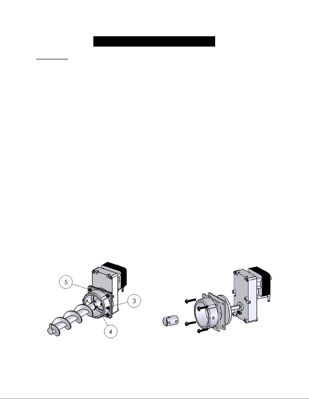
39
IMPORTANT! READ AND FOLLOW ALL INSTALLATION AND MAINTENANCE INSTRUCTIONS, INCLUDING
CLEANING THE UNIT AS SPECIFIED, AND REPLACING GASKETS ANNUALLY, AND PARTS AS NEEDED.
ENGLAND’S STOVE WORKS IS NOT RESPONSIBLE FOR ANY DAMAGE OR INJURY INCURRED DUE TO NEGLECT, OR
DUE TO UNSAFE INSTALLATION OR USAGE OF THIS PRODUCT. CALL TECHNICAL SUPPORT WITH QUESTIONS.
REPLACING COMPONENTS
Auger Motor
1. Before beginning any component replacement, be certain the unit is unplugged and
thoroughly cooled down. Also, make sure the hopper is empty before attempting to
remove or replace the auger motor assembly.
2. Remove the side panels and back panels as previously detailed in this manual on Page 35
and in the “Exhaust Blower Cleaning” section. Before loosening any bolts, detach the
wiring harness from the auger motor.
3. Locate the auger motor assembly at the rear of the stove, and begin by loosening the two
allen set screws on either side of the cast iron auger motor coupler.
4. Slide the auger assembly out of the tube enough that the allen set screw, which holds the
auger to the steel auger coupler, can be accessed. Loosen this set screw until the auger is
free from the auger motor assembly.
5. Next, remove the four screws which hold the cast iron auger motor coupler to the auger
motor, using a 5/16” wrench. Slide the cast iron auger motor coupler and the steel spacer
plate off of the auger motor.
6. Loosen the allen set screw which holds the steel auger coupler to the auger motor output
shaft, and remove the steel auger coupler, as well as the rubber vibration dampener.
7. Reinstall the parts in reverse order on the new auger motor, being careful not to over-
tighten the bolts which hold the cast iron auger coupler to the auger motor.
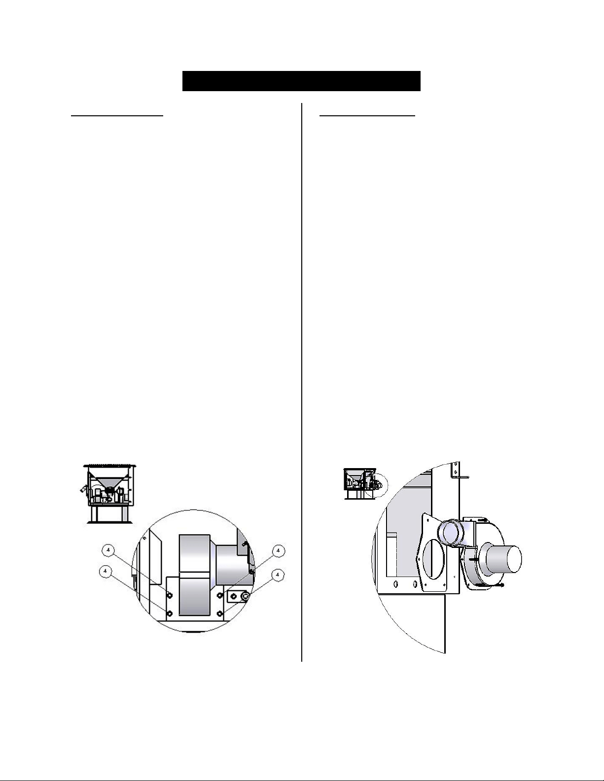
40
IMPORTANT! READ AND FOLLOW ALL INSTALLATION AND MAINTENANCE INSTRUCTIONS, INCLUDING
CLEANING THE UNIT AS SPECIFIED, AND REPLACING GASKETS ANNUALLY, AND PARTS AS NEEDED.
ENGLAND’S STOVE WORKS IS NOT RESPONSIBLE FOR ANY DAMAGE OR INJURY INCURRED DUE TO NEGLECT, OR
DUE TO UNSAFE INSTALLATION OR USAGE OF THIS PRODUCT. CALL TECHNICAL SUPPORT WITH QUESTIONS.
REPLACING COMPONENTS
Convection Blower
1. Before beginning any component
replacement, be certain the unit is
unplugged and thoroughly cooled down.
2. Remove the right side panel as
previously detailed in this manual on
Page 33 in the “Exhaust Blower
Cleaning” section.
3. Detach the convection blower from the
wiring harness before loosening the four
screws which secure it to the convection
shroud of the stove.
4. After loosening and removing the four
screws which hold the blower to the
stove, remove the blower from the
stove.
5. Installation of the new blower is
performed in reverse of removal;
remember to reconnect the new blower
to the wiring harness before reinstalling
the side panel.
Combustion Blower
1. Before beginning any component
replacement, be certain the unit is
unplugged and thoroughly cooled down.
2. Remove the left side panel as previously
detailed on page 33.
3. Disconnect the venting system from the
exhaust blower, and disconnect the
exhaust blower from the stove wiring
harness. Loosen and remove the
thermal sensor screw on the top of the
exhaust blower outlet using a 5/16”
wrench.
4. Loosen and remove all five screws
which hold the exhaust blower to the
exhaust blower tube. Once the screws
have been removed, the blower can be
lifted up and out of the stove.
5. Reinstallation is the exact opposite of
the steps above; however be certain to
check the condition of the exhaust
blower gasket and replace if necessary.
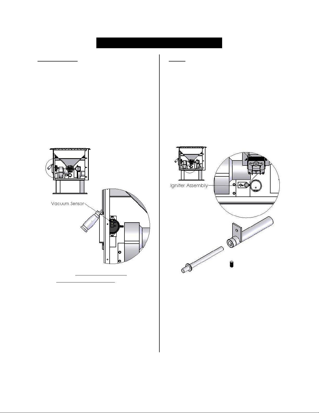
41
IMPORTANT! READ AND FOLLOW ALL INSTALLATION AND MAINTENANCE INSTRUCTIONS, INCLUDING
CLEANING THE UNIT AS SPECIFIED, AND REPLACING GASKETS ANNUALLY, AND PARTS AS NEEDED.
ENGLAND’S STOVE WORKS IS NOT RESPONSIBLE FOR ANY DAMAGE OR INJURY INCURRED DUE TO NEGLECT, OR
DUE TO UNSAFE INSTALLATION OR USAGE OF THIS PRODUCT. CALL TECHNICAL SUPPORT WITH QUESTIONS.
REPLACING COMPONENTS
Vacuum Switch
1. Before beginning any component
replacement, be certain the unit is
unplugged and thoroughly cooled
down.
2. Remove the right side panel and the
back panel as previously detailed.
3. Locate the vacuum sensor as shown
in the diagram below.
4. Disconnect the stove wiring harness
and vacuum hose from the vacuum
sensor, taking note of where
connections were made.
5. Remove the two screws which hold
the vacuum sensor to the vacuum
sensor bracket, using a 5/16”
wrench.
6. Installation is the reverse of removal;
be absolutely certain the wires and
vacuum hose are connected as they
were, and according to the wiring
diagram in this manual.
Igniter
1. Before beginning any component
replacement, be certain the unit is
unplugged and thoroughly cooled
down.
2. Remove the right side panel and the
back panel as previously detailed.
3. Locate the igniter as shown in the
diagram below.
4. Disconnect the igniter wiring from
the control board and use a 5/16”
wrench to remove the igniter
retaining screw.
5. Loosen the allen set screw and
remove the old igniter cartridge.
6. Install the new igniter in the igniter
tube, retighten the set screw and
reinstall the assembly into the stove.
Be certain to reconnect the new
igniter wires to the circuit board
before reassembly.

42
IMPORTANT! READ AND FOLLOW ALL INSTALLATION AND MAINTENANCE INSTRUCTIONS, INCLUDING
CLEANING THE UNIT AS SPECIFIED, AND REPLACING GASKETS ANNUALLY, AND PARTS AS NEEDED.
ENGLAND’S STOVE WORKS IS NOT RESPONSIBLE FOR ANY DAMAGE OR INJURY INCURRED DUE TO NEGLECT, OR
DUE TO UNSAFE INSTALLATION OR USAGE OF THIS PRODUCT. CALL TECHNICAL SUPPORT WITH QUESTIONS.
REPLACING COMPONENTS
Gaskets
1. Door
o This unit comes with a
1
/
2
” rope gasket around the door that should be replaced
annually. To replace the door gasket (Part # AC-DGKEP), the old gasket must
first be removed entirely — prior to adding the new adhesive, you may have to
scrape the old cement from the door channel. Once the cement and gasket have
been added, the door should be closed and latched for twenty-four hours to allow
the cement to harden.
2. Window
o If you are replacing the window gasket (Part # PU-GGK), the new gasket will
already have adhesive on one side. Remove the paper on the adhesive side and
place the gasket around the outside edge of the glass, centered over the edge.
Fold the gasket edges over on the glass, forming a “U” shape.
3. Combustion Blower
o The Combustion Blower Gasket (Part # PU-CBMG) should be inspected
whenever you remove or clean the Combustion Blower and replaced if necessary.
4. In addition, the Hopper Lid gasket should be inspected and replaced annually, or sooner
if necessary (see “Checking Gaskets” in the Yearly Maintenance section).
Finish
This new unit has been painted with High-Temperature Paint that should retain its
original look for years. If the unit should get wet and rust spots appear, the spots can be sanded
with fine steel wool and repainted. It is crucial that only High-Temperature Spray Paint is used
(Part # AC-MBSP), as others may not adhere to the surface or withstand the high temperatures.
Similarly, some brands of paint will not adhere to different brands of paint, so we highly
recommend using our proprietary High-Temperature Spray Paint.
Glass
This unit has a three piece ceramic glass set (Part No. AC-G40 [Center Glass] & Part No.
AC-G41 [Side Glass]) in the viewing door. Self adhesive window gasket is always included
with replacement windows purchased directly from England’s Stove Works. Surface scratches
are acceptable, but if this glass becomes cracked in any area, the unit should be shut down and
the window replaced with ceramic glass bought from England’s Stove Works. Never replace
ceramic glass with tempered or any other type of glass.
IMPROPER GASKET MAINTENANCE, INCLUDING FAILURE TO REPLACE
GASKETS, CAN CAUSE AIR LEAKS RESULTING IN SMOKE-BACKS.
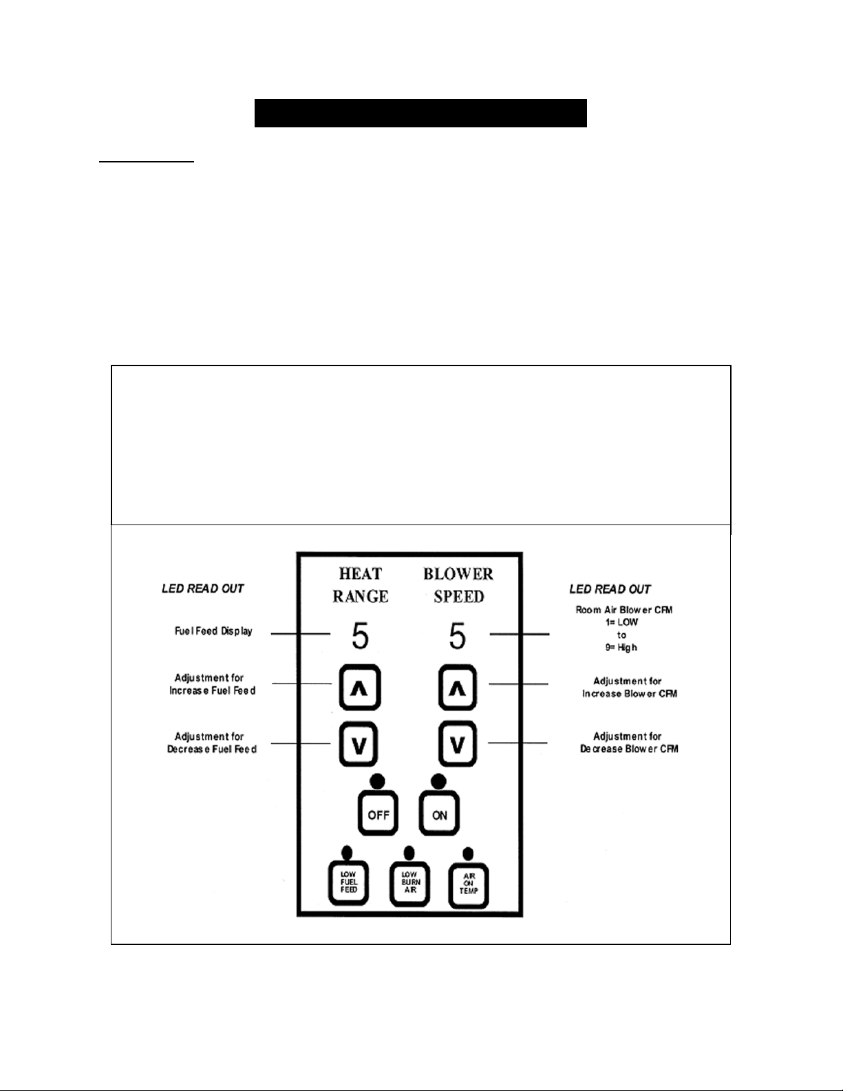
43
IMPORTANT! READ AND FOLLOW ALL INSTALLATION AND MAINTENANCE INSTRUCTIONS, INCLUDING
CLEANING THE UNIT AS SPECIFIED, AND REPLACING GASKETS ANNUALLY, AND PARTS AS NEEDED.
ENGLAND’S STOVE WORKS IS NOT RESPONSIBLE FOR ANY DAMAGE OR INJURY INCURRED DUE TO NEGLECT, OR
DUE TO UNSAFE INSTALLATION OR USAGE OF THIS PRODUCT. CALL TECHNICAL SUPPORT WITH QUESTIONS.
REPLACING COMPONENTS
Control Board
The Control Board (Part # PU-CBEP) is a digital read-out board. This board offers a
wide variety of settings to operate the unit. The right side panel should be removed prior to
removing the control board. The control board can be removed from the unit by loosening the
two outside screws and pulling the board back to the inside. A 6-amp “quick-blow” fuse is used
on this Control Board.
NOTE: The bottom three control buttons are preset at the factory and are not user adjustable.
See the “Daily Operation” section beginning on page 17 of the manual for more
instructions on Control Board settings.
Recommended Heat Ranges:
Low Burn: Heat Range setting: 1 Room Air Blower setting: 1
Medium Low: Heat Range setting: 2 – 3 Room Air Blower setting: *
Medium High: Heat Range setting: 4 – 8 Room Air Blower setting: *
High Burn: Heat Range setting: 9 Room Air Blower setting: 9
* NOTE: Blower Speed will automatically be adjusted to the desired Heat Range
that you select.
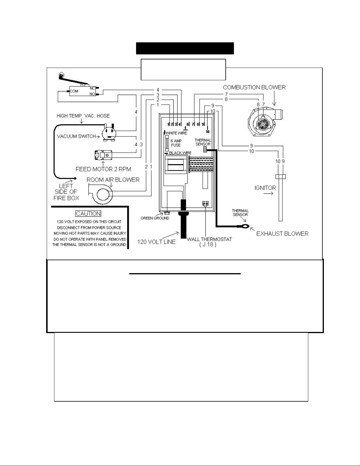
44
IMPORTANT! READ AND FOLLOW ALL INSTALLATION AND MAINTENANCE INSTRUCTIONS, INCLUDING
CLEANING THE UNIT AS SPECIFIED, AND REPLACING GASKETS ANNUALLY, AND PARTS AS NEEDED.
ENGLAND’S STOVE WORKS IS NOT RESPONSIBLE FOR ANY DAMAGE OR INJURY INCURRED DUE TO NEGLECT, OR
DUE TO UNSAFE INSTALLATION OR USAGE OF THIS PRODUCT. CALL TECHNICAL SUPPORT WITH QUESTIONS.
WIRING DIAGRAM
Caution – Shock Hazard
Press the “Off” button and let the appliance completely cool BEFORE
unplugging the appliance and beginning any maintenance or component
replacement.
Risk of shock if appliance is not unplugged before service.
PU-CBEP
Control Board Dia
g
ram
HopperLidSafetySwitch‐Thisunitisalsoequippedwithahoppe rlidsafetyswitch(Part#
AC‐HLSB)whichisdirectlyconnectedtotheaugermotor.Intheeventthehopperlidisleft
openwhilethestoveisinoperation,thehopperlidswitchwillpreventtheaugerfrom
turning.Thisistopreventbyproductsofcombustionfromenteringthehomethroughthe
openhopperlidandalsotosimplypreventoperationwiththehopperlidopen.Improper
hopperlidsafetyswitchoperationwillresultinanaugerthatwillnotturnandthereforea
stovethatwillnot
burn.NEVERplaceyourhandoranyobjectneartheaugerwhilethestove
isconnectedtopower.
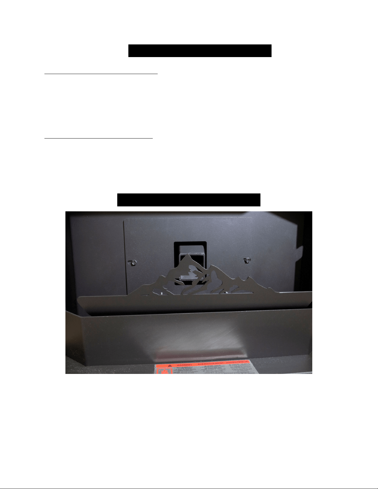
45
IMPORTANT! READ AND FOLLOW ALL INSTALLATION AND MAINTENANCE INSTRUCTIONS, INCLUDING
CLEANING THE UNIT AS SPECIFIED, AND REPLACING GASKETS ANNUALLY, AND PARTS AS NEEDED.
ENGLAND’S STOVE WORKS IS NOT RESPONSIBLE FOR ANY DAMAGE OR INJURY INCURRED DUE TO NEGLECT, OR
DUE TO UNSAFE INSTALLATION OR USAGE OF THIS PRODUCT. CALL TECHNICAL SUPPORT WITH QUESTIONS.
OPTIONAL ACCESSORIES
Wall Thermostat (PU-DTSTAT)
Installing this wall thermostat allows the 25-CBEP to operate on the same
principle as a furnace: The stove will shut-down and relight as the call for heat
comes and goes (in On/Off mode, see Thermostat Operation, page 23). This will
maintain the house at a more constant temperature, while conserving pellets.
Remote Thermostat (AC-3003)
The remote thermostat for the 25-CBEP takes the convenience of thermostat
operation one step further by allowing temperature adjustments from anywhere in
the home. The remote thermostat allows precise temperature control from
wherever you desire and only requires six (6) AA batteries to operate.
STANDARD ACCESSORIES
Your stove is equipped with a decorative steel air wash. While it is designed to
enhance the beauty of the fire, it is also functional in that it helps to maintain a
cleaner door glass. This air wash should lean forward (toward the glass) when the
stove is in operation. Be sure to check heatredefined.com periodically for future air
wash designs to change the look of your stove.
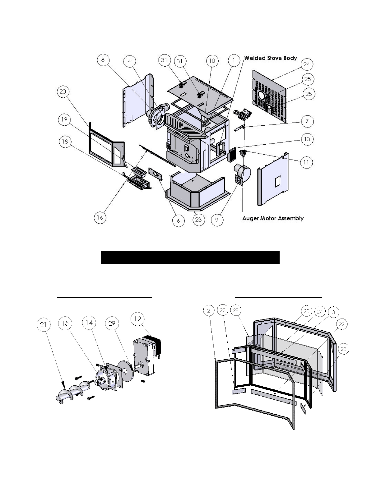
46
IMPORTANT! READ AND FOLLOW ALL INSTALLATION AND MAINTENANCE INSTRUCTIONS, INCLUDING
CLEANING THE UNIT AS SPECIFIED, AND REPLACING GASKETS ANNUALLY, AND PARTS AS NEEDED.
ENGLAND’S STOVE WORKS IS NOT RESPONSIBLE FOR ANY DAMAGE OR INJURY INCURRED DUE TO NEGLECT, OR
DUE TO UNSAFE INSTALLATION OR USAGE OF THIS PRODUCT. CALL TECHNICAL SUPPORT WITH QUESTIONS.
ILLUSTRATED PARTS DIAGRAM
Auger Motor Assembly Steel Door Assembly

47
IMPORTANT! READ AND FOLLOW ALL INSTALLATION AND MAINTENANCE INSTRUCTIONS, INCLUDING
CLEANING THE UNIT AS SPECIFIED, AND REPLACING GASKETS ANNUALLY, AND PARTS AS NEEDED.
ENGLAND’S STOVE WORKS IS NOT RESPONSIBLE FOR ANY DAMAGE OR INJURY INCURRED DUE TO NEGLECT, OR
DUE TO UNSAFE INSTALLATION OR USAGE OF THIS PRODUCT. CALL TECHNICAL SUPPORT WITH QUESTIONS.
PartNumber PartDescription Diagram#
Gaskets
PU‐HLG HopperLidGasket 1
AC‐DGKEP DoorGasket 2
AC‐GGKEP ThreePieceWindowGasketKit 3
PU‐CBMG ExhaustBlower&MotorGasket 4
PU‐CGEP CradleMatingGasket 6
ElectricalComponents
PU‐CHA IgniterCartridgeHeater 7
PU‐076002B ExhaustBlower 8
PU‐4C442 RoomAirBlower 9
AC‐HLSB HopperLidSwitch 10
CU‐VS .05"ofWCVacuumSwitch 11
CU‐047042 2RPMAugerMotor 12
PU‐CBEP ControlBoard 13
CastIron
CA‐AMPP CastIronAugerMotorCollar 14
Steel
CA‐AC SteelAugerCoupler 15
IP‐25EP ExhaustCover 16
PU‐BPCEP Cradle 18
PU‐BPEP Burnpot 19
CA‐40 SteelDoor 20
DecorativeSteelAirWash Notshown
PU‐AFEP SteelAuger 21
AC‐GSEP GlassSupportBrackets 22
PU‐BREP PedestalBaseandRiser23
PU‐RAPEP RearAccessPanel 24
PU‐EPRCP ExhaustandIntakeCoverPlates 25
Glass
AC‐G40 ThreePieceGlass‐Center 27
AC‐G41 ThreePieceGlass‐Side 28
Misc
CU‐RG RubberAugerMotorBushing 29
PU‐VH HighTemp.VacuumHose NotShown
PU‐62‐40‐151‐3 HopperLidLatch 31
AC‐SHN NickelSpringHandle NotShown
AC‐SH BrassSpringHandle NotShown
PU‐EDIC ExhaustTubeInsulationWrap NotShown
REPLACEMENT PARTS LIST
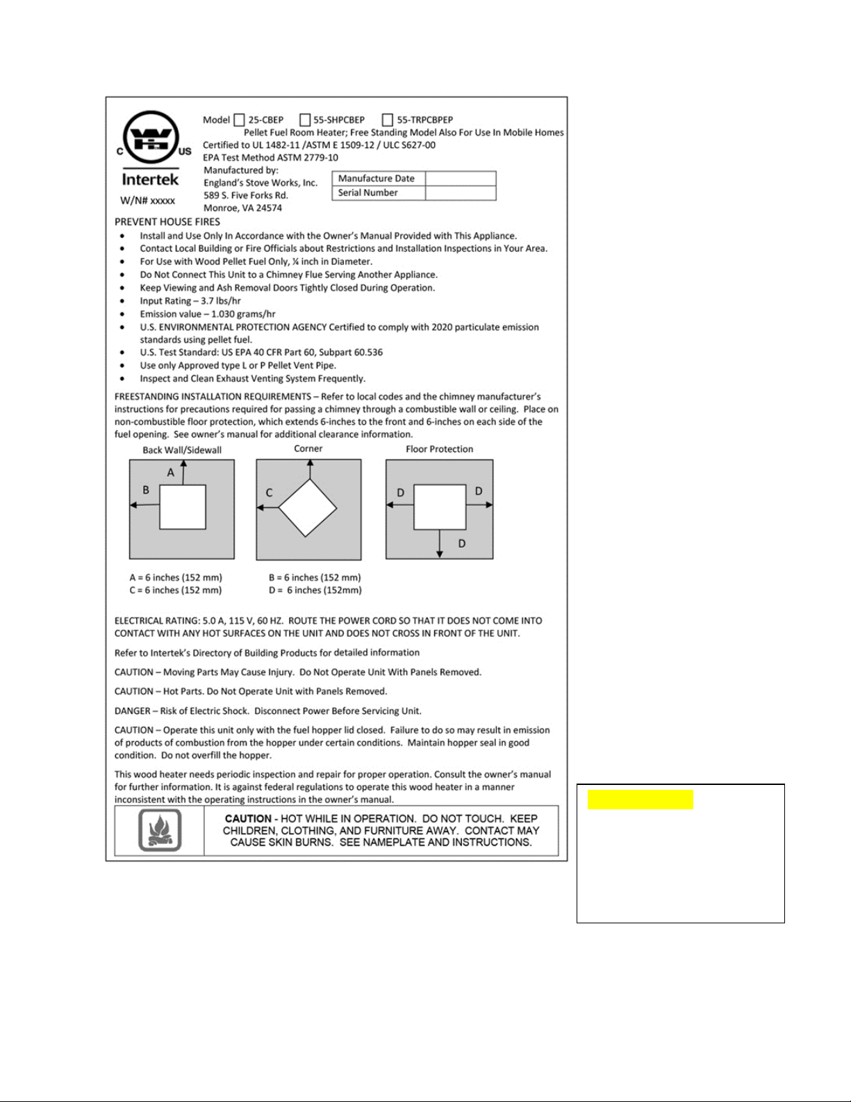
48
IMPORTANT! READ AND FOLLOW ALL INSTALLATION AND MAINTENANCE INSTRUCTIONS, INCLUDING
CLEANING THE UNIT AS SPECIFIED, AND REPLACING GASKETS ANNUALLY, AND PARTS AS NEEDED.
ENGLAND’S STOVE WORKS IS NOT RESPONSIBLE FOR ANY DAMAGE OR INJURY INCURRED DUE TO NEGLECT, OR
DUE TO UNSAFE INSTALLATION OR USAGE OF THIS PRODUCT. CALL TECHNICAL SUPPORT WITH QUESTIONS.
This sample tag shows the
safety info. such as
UL/ULC testing standard,
etc. for your local officials,
or anyone else who may
need reference information.

49
IMPORTANT! READ AND FOLLOW ALL INSTALLATION AND MAINTENANCE INSTRUCTIONS, INCLUDING
CLEANING THE UNIT AS SPECIFIED, AND REPLACING GASKETS ANNUALLY, AND PARTS AS NEEDED.
ENGLAND’S STOVE WORKS IS NOT RESPONSIBLE FOR ANY DAMAGE OR INJURY INCURRED DUE TO NEGLECT, OR
DUE TO UNSAFE INSTALLATION OR USAGE OF THIS PRODUCT. CALL TECHNICAL SUPPORT WITH QUESTIONS.
LIMITED FIVE (5) YEAR WARRANTY
From the date of purchase to the original owner
Model Numbers 25-CBEP / 55-SHPCBEP / 55-TRPCBEP
The manufacturer extends the following warranties:
Five Year Period:
1. Carbon steel and welded seams in the firebox are covered for five (5) years
against splitting.
2. The steel door and hinges are covered for five (5) years against cracking.
One Year Period:
1. Component parts such as the hopper, auger, burn-pot, baffle plate, auger
shaft and fasteners are covered for one (1) year against cracking, breakage
and welded seam separation.
2. Electrical components, accessory items, glass and the painted surface of the
stove are covered for one (1) year from the date of purchase.
Conditions and Exclusions
1. Damage resulting from over-firing will void your warranty.
2. This warranty does not apply if damage occurs because of an accident,
improper handling, improper installation, improper operation, abuse or
unauthorized repair made or attempted to be made.
3. The manufacturer is not liable for indirect, incidental, or consequential
damages in connection with the product including any cost or expense,
providing substitute equipment or service during periods of malfunction or
non-use.*
4. All liability for any consequential damage for breach of any written or
implied warranty is disclaimed and excluded.
5. This unit is EPA certified using high quality, Premium Grade pellet fuel.
Warranty is void if the unit is used to burn materials for which the unit is not
certified by the EPA. Warranty is void if unit is not used according to the
owner’s manual.
Some states do not allow the exclusion of limitations of incidental or consequential damages, so the above may not apply to you.

50
IMPORTANT! READ AND FOLLOW ALL INSTALLATION AND MAINTENANCE INSTRUCTIONS, INCLUDING
CLEANING THE UNIT AS SPECIFIED, AND REPLACING GASKETS ANNUALLY, AND PARTS AS NEEDED.
ENGLAND’S STOVE WORKS IS NOT RESPONSIBLE FOR ANY DAMAGE OR INJURY INCURRED DUE TO NEGLECT, OR
DUE TO UNSAFE INSTALLATION OR USAGE OF THIS PRODUCT. CALL TECHNICAL SUPPORT WITH QUESTIONS.
Procedure
Purchaser must give notice of claim of defect within the warranty period and
pay transportation to and from a service center designated by the manufacturer.
The dealer from which the unit was purchased or the factory, at our option, will
perform the warranty service.
Other Rights
This warranty gives you specific legal rights; you may also have other rights,
which may vary from state to state.
England’s Stove Works, Inc.
P.O. Box 206
Monroe, VA 24574
(800) 245-6489
To submit a Warranty Claim, call (800) 245-6489 to speak with our Technical
Support department. You may also file a Warranty Claim at
www.heatredefined.com
For parts, warranty replacement procedures may be found at our parts store site:
store.heatredefined.com
Please Note: This warranty is null and void if the attached warranty registration AND
a copy of the sales receipt is not returned within thirty (30) days from the date of
purchase.
Warranty is not transferable.

51
IMPORTANT! READ AND FOLLOW ALL INSTALLATION AND MAINTENANCE INSTRUCTIONS, INCLUDING
CLEANING THE UNIT AS SPECIFIED, AND REPLACING GASKETS ANNUALLY, AND PARTS AS NEEDED.
ENGLAND’S STOVE WORKS IS NOT RESPONSIBLE FOR ANY DAMAGE OR INJURY INCURRED DUE TO NEGLECT, OR
DUE TO UNSAFE INSTALLATION OR USAGE OF THIS PRODUCT. CALL TECHNICAL SUPPORT WITH QUESTIONS.
WARRANTY REGISTRATION for England’s Stove Works®
Purchaser Information
I. Purchased By (Name) _________________________________________
II. Address ____________________________________________________
III. City_______________________State________Zip Code ____________
IV. Telephone Number ___________________________________________
V. Email Address _______________________________________________
Dealer Information
VI. Purchased From _____________________________________________
VII. Address ___________________________________________________
VIII. City_______________________ State________ Zip Code __________
Unit Information
*Refer to the sticker on the back of the manual or box to complete this section.
IX. Model Number_____________________ Purchase Date _____________
X. Purchase Price_____________________
XI. Serial Number_____________________ Mfg. Date _________________
Purchase Questions
How did you first hear about our product? (Please check one)
Word of Mouth ____ Burn Trailer Demonstration____ Internet____
Other: ________________________________________________________
Where did you receive information about our product?
Via Telephone____ Dealer (Name of dealer) ___________ Internet____
Other: ________________________________________________________

52
IMPORTANT! READ AND FOLLOW ALL INSTALLATION AND MAINTENANCE INSTRUCTIONS, INCLUDING
CLEANING THE UNIT AS SPECIFIED, AND REPLACING GASKETS ANNUALLY, AND PARTS AS NEEDED.
ENGLAND’S STOVE WORKS IS NOT RESPONSIBLE FOR ANY DAMAGE OR INJURY INCURRED DUE TO NEGLECT, OR
DUE TO UNSAFE INSTALLATION OR USAGE OF THIS PRODUCT. CALL TECHNICAL SUPPORT WITH QUESTIONS.
ImportantNotice
ThisregistrationinformationMUSTbeonfileforthiswarrantytobevalid.Please
sendthisinformationwithinthirty(30)daysfromtheoriginaldateofpurchase.
Useanyofthesethreeeasywaystosendyourwarrantyinformationin!
MailingAddress
England’sStoveWorks,Inc.
TechnicalsupportDepartment
P.O.Box206
Monroe,Virginia24574
FaxNumber
(434)929‐4810–Twenty‐fourhoursaday
OnlineRegistration
Toregisteronline,visitourwarrantyregistrationwebsiteat:
http://www.heatredefined.com
Please Note: This warranty is null and void if the attached warranty registration AND a
copy of the sales receipt is not returned within thirty (30) days from the date of purchase.
Warranty is not transferable.

53
IMPORTANT! READ AND FOLLOW ALL INSTALLATION AND MAINTENANCE INSTRUCTIONS, INCLUDING
CLEANING THE UNIT AS SPECIFIED, AND REPLACING GASKETS ANNUALLY, AND PARTS AS NEEDED.
ENGLAND’S STOVE WORKS IS NOT RESPONSIBLE FOR ANY DAMAGE OR INJURY INCURRED DUE TO NEGLECT, OR
DUE TO UNSAFE INSTALLATION OR USAGE OF THIS PRODUCT. CALL TECHNICAL SUPPORT WITH QUESTIONS.
PLEASENOTE:
EPAINFORMATION
Thefollowingadditionstoyourowner’smanualwillenableyoutoachieve
optimalemissionsperformancefromyourstove.Importantsafetytipsarealso
included.
‐ ProperInstallation–PleaserefertotheInstallationsectionofyourowner’smanualand
followtheguidelineslistedthereinforsafetyandforoptimalemissionsperformance.
Additionalinformation:
Venting:
Besuretofollowyourowner’smanual’srecommendationforventing,includingthepropertypes
offluesystemsandpelletventpipe.
AlsonotethatOutsideAirConnection(combustionair)isMANDATORYforpropersafeoperation,
andtoachieveoptimalemissionsperformance.
Observetheventterminationclearancesspecifiedinyourowner’smanual,
andcontactour
TechnicalSupportifyouhaveanyquestions.Phone(800)245‐6489oremail
Becertainthatallaspectsoftheventingsystemareinstalledtotheventing
manufacturer’sinstructions,particularlytherequiredclearancestocombustibles.
Yourpelletstoveoperatesonanegativedraftsystem,whichpullscombustionair
throughtheburnpotandpushestheexhaustairthroughtheventpipeandoutofthe
building.Thisunitmustbeinstalledinaccordancewithyourowner’smanual’sdetailed
descriptionsofventingtechniques;notinstallingthestoveinaccordancewiththedetails
listedcanresultinpoorstoveperformance(includingpooremissions),propertydamage,
bodilyinjuryordeath.England’sStoveWorksisnotresponsibleforany damageincurreddue
toapoororunsafeinstallation.
PELLET – Additionalsafetyandemissionstips

54
IMPORTANT! READ AND FOLLOW ALL INSTALLATION AND MAINTENANCE INSTRUCTIONS, INCLUDING
CLEANING THE UNIT AS SPECIFIED, AND REPLACING GASKETS ANNUALLY, AND PARTS AS NEEDED.
ENGLAND’S STOVE WORKS IS NOT RESPONSIBLE FOR ANY DAMAGE OR INJURY INCURRED DUE TO NEGLECT, OR
DUE TO UNSAFE INSTALLATION OR USAGE OF THIS PRODUCT. CALL TECHNICAL SUPPORT WITH QUESTIONS.
AdditionalVentingInformation
Donotmixandmatchcomponentsfromdifferentpipemanufacturerswhenassembling
yourventingsystem(i.e.DoNOTuseventingpipefromonemanufacturerandathimble
fromanother).
Werequireaminimumverticalriseof36in.(3ft.)ofpipetocreatenaturaldraftinthe
system,whichhelpsevacuatesmokefromthestoveintheeventofapowerfailureor
combustionblowerfailure.
Ventingsystems15.0ft.orshortermaybecomposedentirelyof3.0in.pelletpipe;to
reducefrictionallosses,ventingsystemslongerthan15.0ft.shouldbecomposedof4.0
in.pelletpipe.
Donotterminatetheventingsystemdirectlybeneathanycombustiblestructuresuchas
aporchordeck.
FollowNFPA211ruleslistedbelowforventingsystemterminationlocationrelativeto
windowsandotheropeningsinthedwelling.
o NFPA211(2006ed.)Section10.4Termination:10.4.5
(1)Theexitterminalofamechanicaldraftsystemotherthandirectvent
appliances(sealedcombustionsystemappliances)shallbelocatedinaccordance
withthefollowing:
(a)Notlessthan3ft.(.91m)aboveanyforcedairinletlocatedwithin10
ft.(3.0m).
(b)Notlessthan4ft.(1.2m)below,4ft.(1.2m)horizontallyfromor1ft.
(305mm)aboveanydoor,windoworgravityairinletintoanybuilding.
(c)Notlessthan2ft.(0.61m)fromanadjacentbuildingandnotlessthan
7ft.(2.1m)abovegradewhenlocatedadjacenttopublicwalkways.
Distancebetweentheterminationopeningandgradeshouldbeaminimumof2ft.(24
in.)contingentonthegradesurfacebelowthetermination.Whendeterminingthe
terminationheightabovegrade,considersnowdriftlinesandcombustiblessuchas
grassorleafaccumulation.Inareaswheresignificantsnowfallispossible,the
terminationheightmustbesufficientlyhightokeeptheterminationfreeofsnow
accumulation.
Donotusemakeshiftcompromisesduringinstallationorinstallanycomponentofthe
unitorventingsysteminsuchamannerthatcouldresultinahazardousinstallation.
Achimneyconnectorshallnotpassthroughanatticorroofspace,closetorsimilar
concealedspace,orafloor,orceiling.
Wherepassagethroughawallorpartitionofcombustiblematerialisdesired,the
installationshallconformtoCAN/CSA‐B365.
WARNING:
VentingsystemsurfacesgetHOT,andcancauseburnsiftouched.Noncombustible
shieldin
g
or
g
uardsma
y
bere
q
uired.

55
IMPORTANT! READ AND FOLLOW ALL INSTALLATION AND MAINTENANCE INSTRUCTIONS, INCLUDING
CLEANING THE UNIT AS SPECIFIED, AND REPLACING GASKETS ANNUALLY, AND PARTS AS NEEDED.
ENGLAND’S STOVE WORKS IS NOT RESPONSIBLE FOR ANY DAMAGE OR INJURY INCURRED DUE TO NEGLECT, OR
DUE TO UNSAFE INSTALLATION OR USAGE OF THIS PRODUCT. CALL TECHNICAL SUPPORT WITH QUESTIONS.
OUTSIDEAIRHOOK‐UP
Theuseofoutsidecombustionairismandatoryonthispelletstove.
Theoutsideairconnectionpipeprotrudesfromthelowerrearcenterofthestove;usethe
includedoutsideairkittoattachyourstovetooutsidecombustionair.Instructionsandall
thepartsneededtomaketheoutsideairconnectiontoyourpelletstoveareincludedwith
theoutsideairkit.
Ifitisnotfeasibletousetheincludedoutsideairhookupkitinyourstoveinstallation,other
materialsmaybeused,providedthefollowingrulesarefollowed:
o Thepipeusedforoutsideairhookupmustbemetal,withaminimumthicknessof
.0209in.(25gaugemildsteel)orgreaterandaninsidediameterofapproximately
2.0in.
o Allpipejointsandconnectionsshouldbesealedwithpipeclampsorother
mechanicalmeans,toinsurealeakfreeoutsideairconnection.
o Longrunsofpipeandexcessiveelbowsforoutsideairshouldbeavoided.Dueto
frictionalresistanceinpipe,anyexcessiveoutsideairpipingcanresultinpoorstove
performance.
o Ascreenorotherprotectiondevicemustbefittedovertheoutsideairtermination
pointtopreventrain,debrisandnuisanceanimalsfromenteringthepipingsystem.
o Increasetheoutsideairpipesizeto3.0in.diameterpipeiftheoutsideair
connectionismorethan6ft.inlength,morethantwo(2)elbowsareusedorifthe
stoveisinstalledinabasement.
o Theoutsideairconnectionsystemshouldbeinspectedatleastannuallytobecertainit
isfreefromblockage.
‐ OperationandMaintenance–Pleaserefertothe‘Operation’(OperatingInstructions)
andMaintenance(includingAshRemoval/Disposal)sectionsofyourowner’smanual
andfollowtheguidelineslistedthereinforsafetyandforoptimalemissions
performance.
AdditionalInformation:
Followingtheinstructionsinyourowner’smanualforStart‐Up(lightingafire)willensurea
properfire,aswellashelpingminimizevisibleemissions.

56
IMPORTANT! READ AND FOLLOW ALL INSTALLATION AND MAINTENANCE INSTRUCTIONS, INCLUDING
CLEANING THE UNIT AS SPECIFIED, AND REPLACING GASKETS ANNUALLY, AND PARTS AS NEEDED.
ENGLAND’S STOVE WORKS IS NOT RESPONSIBLE FOR ANY DAMAGE OR INJURY INCURRED DUE TO NEGLECT, OR
DUE TO UNSAFE INSTALLATION OR USAGE OF THIS PRODUCT. CALL TECHNICAL SUPPORT WITH QUESTIONS.
More:
‐ Fuelloadingandre‐loading:PracticalTipsforBuildingaFire–Seeyourowner’smanual
forinformationonloading(andre‐loading)yourfuel,aswellasforfire‐starting
procedures.
‐ FuelSelection:Onceyourapplianceisproperlyinstalled,besuretofollowyourowner’s
manualregardingfuelselectionandstartingandoperatingyourappliance,includingthe
followingpracticaltipsthatwillhelpyouobtainthebestefficiencyfromyour stove.
‐
DailyOperationNotes
Onlyhighquality,¼”(.25in.)diameterwoodpellets,shouldbeusedinthisstove.Usinglow
gradewoodpelletswithhighashcontentORwoodpelletswithahighmoisturecontent
cancausetheburnpottofillwithashatamorerapidpaceandcancauseintervalsbetween
periodicmaintenancetobecomesignificantlyshorter.Pleasereadthe“Maintenance”
sectionofthismanualthoroughlytounderstandhowfuelselectionaffectsstoveoperation,
maintenanceandcleaning.
Variationintheflameheightisnormal;notallwoodpelletfuelisuniforminsize,whichcan
affectthewaypelletsarefedintotheburnpot.Althoughtheflameheightmayincrease
anddecreaseduringoperation,thereisnolossofefficiency.
Alwaysstorewoodpelletfuelinadrylocation;storingwoodpelletfuelinadrylocation
ensuresthefuelwillremainpelletizedandlowinmoisturecontent.Also,becertainthatall
woodpelletfuelisstoredatasafedistancefromthepelletheater;storingfuelinclose
proximitytothestovecanresultinafire.
Thispelletburningroomheaterisequippedwithaspeciallydesignedburnpotwhichcomes
preinstalledfromthefactory.Thisburnpotelevatestheburningpelletsanddeliversairatthe
precisely‐requiredlocations.Pelletsmustonlybeburnedinthefactoryburnpot;no
modificationsshouldbemadetothisburnpotandnoadditionalgratesorotherfireelevators
shouldbeused.

57
IMPORTANT! READ AND FOLLOW ALL INSTALLATION AND MAINTENANCE INSTRUCTIONS, INCLUDING
CLEANING THE UNIT AS SPECIFIED, AND REPLACING GASKETS ANNUALLY, AND PARTS AS NEEDED.
ENGLAND’S STOVE WORKS IS NOT RESPONSIBLE FOR ANY DAMAGE OR INJURY INCURRED DUE TO NEGLECT, OR
DUE TO UNSAFE INSTALLATION OR USAGE OF THIS PRODUCT. CALL TECHNICAL SUPPORT WITH QUESTIONS.
WHATFUELSNOTTOUSE:
CAUTION
NEVERUSEGASOLINE,GASOLINE‐TYPELANTERNFUEL,KEROSENE,CHARCOAL
LIGHTERFLUID,ORSIMILARLIQUIDSTOSTARTOR“FRESHENUP”AFIREINTHIS
HEATER.KEEPALLSUCHLIQUIDSWELLAWAYFROMTHEHEATERWHILEINUSE.
ADDITIONALLY,NEVERAPPLYFIRE‐STARTERTOANYHOTSURFACEOREMBERSINTHE
STOVE.DONOTUSECHEMICALSORFLUIDSTOSTARTTHEFIRE.
DONOTBURNFLAMMABLEFLUIDSSUCHASGASOLINE,NAPHTHAORENGINEOIL.
DONOTBURNGARBAGE;LAWNCLIPPINGSORYARDWASTE;MATERIALS
CONTAININGRUBBER,INCLUDINGTIRES;MATERIALSCONTAININGPLASTIC;WASTE
PETROLEUMPRODUCTS,PAINTORPAINTTHINNERS,ORASPHALTPRODUCTS;
MATERIALSCONTAININGASBESTOS;CONSTRUCTIONORDEMOLITIONDEBRIS;
RAILROADTIESORPRESSURE‐TREATEDWOOD;MANUREORANIMALREMAINS;SALT
WATERDRIFTWOODOROTHERPREVIOUSLYSALTWATERSATURATEDMATERIALS;
UNSEASONEDWOOD;PAPERPRODUCTS,CARDBOARD,PLYWOODOR
PARTICLEBOARD.THEPROHIBITIONAGAINSTBURNINGTHESEMATERIALSDOESNOT
PROHIBITTHEUSEOFFIRESTARTERSMADEFROMPAPER,CARDBOARD,SAWDUST,
WAXANDSIMILARSUBSTANCESFORTHEPURPOSEOFSTARTINGAFIREINAN
AFFECTEDWOODHEATER.BURNINGTHESEMATERIALSMAYRESULTINRELEASEOF
TOXICFUMESORRENDERTHEHEATERINEFFECTIVEANDCAUSESMOKE.
‐ AirControls:Yourpelletstoveisequippedwithacontrolboardthatautomatically
adjuststheairtofuelratioforoptimumemissions.Seeyourowner’smanualfor
informationonoperatingthecontrolboard,andforotheroperationalinformationon
achievingthebestburn,includingthesetips:
Thecontrolboardonthisstoveallowstheusertoadjusttheheatoutputandconvection
blowerspeed,andturntheunitonandoff.
Thelowerbuttonsonthecontrolboard(LowFuelFeed,LowBurnAir,andAironTemp)are
notmeanttobeadjustedduringnormaloperationoftheunit.Thesebuttonsarefactory
presetandshouldnotbeadjustedbytheuser.
Toenergizetheunitandinitiateafire,pressthe“On”button.TheLEDabovethebutton
shouldturngreenandthecontrolboardshoulddisplay“SU”shortlyafterpressingthe
button.

58
IMPORTANT! READ AND FOLLOW ALL INSTALLATION AND MAINTENANCE INSTRUCTIONS, INCLUDING
CLEANING THE UNIT AS SPECIFIED, AND REPLACING GASKETS ANNUALLY, AND PARTS AS NEEDED.
ENGLAND’S STOVE WORKS IS NOT RESPONSIBLE FOR ANY DAMAGE OR INJURY INCURRED DUE TO NEGLECT, OR
DUE TO UNSAFE INSTALLATION OR USAGE OF THIS PRODUCT. CALL TECHNICAL SUPPORT WITH QUESTIONS.
Toshuttheunitdown,pressthe“Off”button.TheLEDabovethebuttonshouldturnred
andtheboardshoulddisplay“Sd”shortlyafterpressingthebutton.Thisinitiatestheshut
downsequence,andthestovewillremaininshutdownmodeuntilithascooleddown.
Toincreasetheheatoutputofthestove,pressthe“Up”heatrangebutton.Thenumberin
theheatrangedisplaywindowwillincrease,signifyingthatthecontrolboardisnow
adjustingtheheatoutputtoyourdesiredlevel.Theblowerspeedwillincreasethesame
amountastheheatrange,becausethestoveisdesignedtooperatewiththeblowerspeed
greaterthanorequaltotheheatrange.Pressingthe“Down”arrowwilldecreasetheheat
rangeandblowerspeed.
Toincreasetheblowerspeedwithoutincreasingtheheatrange,presstheBlowerSpeed
“Up”arrowuntilthedesiredblowerspeedisshowninthedisplaywindow.Pressingthe
“Down”arrowwilldecreasetheblowerspeed;however,thecontrolboardwillnotallow
theblowerspeedtobesetlowerthantheheatrange.
Caution
Thisunitismeanttooperateonlywiththemainviewingdoorclosed.Smoke
spillageandaninefficient,lazyburnwillresultfromattemptingtooperatethe
stovewiththedooropen.
Inaddition,usingfuelotherthanwoodpelletscancreateanunsafesituation
andcanalsogenerateexcesscarbonmonoxide.Carbonmonoxideisan
odorless,colorlessgaswhichcanbedeadly.Besuretoburnonlywoodpellets.
CarbonMonoxideDetector
England’sStoveWorks,Inc.highlyrecommendstheuseofacarbonmonoxide
detectorintheproximityofthestoveandoneperfloorofthehome.Acertain
amountofcarbonmonoxideisproducedwithinthestoveasaby‐productofcombustion.All
exhaustventconnectionsmustbesealedwithRTVSiliconetoassureatightseal.Anyleaksinto
aconfinedareacausedbyfaultyinstallationorimproperoperationofthestovecouldproduce
dizziness,nauseaandinextremecases,death.
‐ ASHREMOVAL–FollowyourOwner’smanual’sinstructionsregardingremovaland
disposalofashes.AlsobesuretofollowALLMaintenancerequirementsaslisted.

59
IMPORTANT! READ AND FOLLOW ALL INSTALLATION AND MAINTENANCE INSTRUCTIONS, INCLUDING
CLEANING THE UNIT AS SPECIFIED, AND REPLACING GASKETS ANNUALLY, AND PARTS AS NEEDED.
ENGLAND’S STOVE WORKS IS NOT RESPONSIBLE FOR ANY DAMAGE OR INJURY INCURRED DUE TO NEGLECT, OR
DUE TO UNSAFE INSTALLATION OR USAGE OF THIS PRODUCT. CALL TECHNICAL SUPPORT WITH QUESTIONS.
‐ REPLACEMENTofpartsthatarecriticaltoemissionsperformance–FollowyourOwner’s
manual’sinstructionsregardingreplacementofgasketsandotherpartsthatarecritical
toemissionsperformance.
Remember:“Thiswoodheaterneedsperiodicinspectionandrepairforproperoperation.Itis
againstfederalregulationstooperatethiswoodheaterinamannerinconsistentwithoperating
instructionsinthismanual.”
‐ SmokeDetectors
England’sStoveWorks,Inc.highlyrecommendstheuseofsmokedetectorsineveryroomof
thehouse.However,locatingasmokedetectordirectlyabovethisunitcanresultinnuisance
alarms.
‐ Compliance:“Thisnon‐catalyticwoodheatermeetsthe2015U.S.Environmental
ProtectionAgency’swoodemissionlimitsforwoodheaterssoldafterMay15,2015.”
‐ TamperWarning:“Thiswoodheaterhasamanufacturer‐setminimumlowburnrate
thatmustnotbealtered.Itisagainstfederalregulationstoalterthissettingor
otherwiseoperatethiswoodheaterinamannerinconsistentwithoperating
instructionsinthismanual.”
‐ Warranty:SeeyourOwner’smanualforaWarrantyRegistrationinstructionpage,as
wellasinstructionsforwarrantyprocedures.Forparts,warrantyreplacement
proceduresmaybefoundatourpartsstoresite:www.heatredefined.com

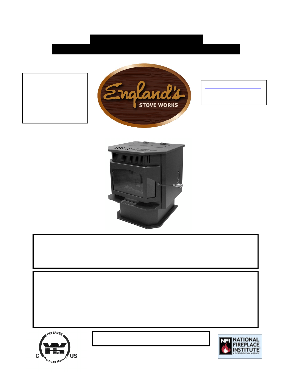
POÊLE À GRANULES CBEP
GUIDE D’INSTALLATION ET D’UTILISATION
ATTENTION
Veuillez lire l’intégralité du présent guide avant d’installer et d’utiliser cet
appareil de chauffage à granules. Gardez tout appareil de chauffage hors de
p
ortée des enfants, et à bonne distance des meubles et des matières combustibles.
AVIS DE SÉCURITÉ
Le non-respect de ces instructions peut causer des dommages matériels,
des blessures ou même la mort. Pour votre sécurité et votre protection, suivez
les instructions pour l’installation décrites dans ce guide. Communiquez avec
les autorités locales en matière de construction ou le service d’incendie afin
de connaître les restrictions et les exigences d’inspection des installations
(y
com
p
ris l’o
b
tention de
p
ermis
)
de votre ré
g
ion.
CONSERVEZ CES INSTRUCTIONS
MODÈLES
25-CBEP 55-SHPCBEP 55-TRPCBEP
www.heatredefined.com
Pièces : 800 516-3636
Soutien : 800 245-6489
Fabriqué par :
England’s Stove Works,
Inc.
PO Box 206
Monroe, VA 24574,
États-Unis
Rév. 1/2019

2
IMPORTANT! LISEZ ET SUIVEZ TOUTES LES INSTRUCTIONS POUR L’INSTALLATION ET L’ENTRETIEN,
NOTAMMENT CELLES PORTANT SUR LE NETTOYAGE DU POÊLE À EFFECTUER SELON LES DIRECTIVES ET
CELLES PORTANT SUR LE REMPLACEMENT DES JOINTS (ANNUELLEMENT) ET DES PIÈCES (AU BESOIN).
ENGLAND’S STOVE WORKS N’EST PAS RESPONSABLE DES DOMMAGES NI DES BLESSURES, QUELS QU’ILS SOIENT,
SUBIS EN RAISON DE NÉGLIGENCE OU À CAUSE D’UNE INSTALLATION OU D’UNE UTILISATION DANGEREUSE
DE CE PRODUIT. POUR TOUTE QUESTION, COMMUNIQUEZ AVEC LE SERVICE DE SOUTIEN TECHNIQUE.
AVERTISSEMENT :
L’air de combustion utilisé par ce poêle doit provenir de
l’extérieur.
Ne pas utiliser cet appareil avec la trémie ouverte; le couvercle
doit être fermé et bien verrouillé au cours de l’utilisation.
À conserver dans vos dossiers
Numéro de modèle________________________
Date d’achat_____________________________
Date de fabrication________________________
Numéro de série__________________________
* Ces renseignements sur la sécurité sont inscrits sur l’étiquette fixée sous
le couvercle de la trémie. Ayez ces renseignements à portée de la main si
vous appelez le fabricant ou votre détaillant au sujet de ce produit.
IMPORTANT : EN CAS DE PROBLÈME AVEC CET APPAREIL,
NE LE RETOURNEZ PAS AU DÉTAILLANT. APPELEZ LA
LIGNE DE SOUTIEN TECHNIQUE AU 1 800 245-6489.
Remarque : England’s Stove Works recommande de ne pas utiliser
un poêle à granules comme unique source de chaleur.
Utilisation dans une maison mobile :
L’utilisation de ce poêle autoportant est approuvée pour des maisons
mobiles ou pour une installation en double largeur avec raccordement
à l’extérieur pour l’air de combustion. Consultez la section
« Installation » du présent guide pour connaître les détails relatifs à
l’installation dans une maison mobile. L’installation dans une maison
mobile doit être conforme à la norme Manufactured Home and Safety
Standard
(
HUD
),
CFR 3280
,
p
artie 24
,
des États-Unis.

3
IMPORTANT! LISEZ ET SUIVEZ TOUTES LES INSTRUCTIONS POUR L’INSTALLATION ET L’ENTRETIEN,
NOTAMMENT CELLES PORTANT SUR LE NETTOYAGE DU POÊLE À EFFECTUER SELON LES DIRECTIVES ET
CELLES PORTANT SUR LE REMPLACEMENT DES JOINTS (ANNUELLEMENT) ET DES PIÈCES (AU BESOIN).
ENGLAND’S STOVE WORKS N’EST PAS RESPONSABLE DES DOMMAGES NI DES BLESSURES, QUELS QU’ILS SOIENT,
SUBIS EN RAISON DE NÉGLIGENCE OU À CAUSE D’UNE INSTALLATION OU D’UNE UTILISATION DANGEREUSE
DE CE PRODUIT. POUR TOUTE QUESTION, COMMUNIQUEZ AVEC LE SERVICE DE SOUTIEN TECHNIQUE.
BIENVENUE!
Introduction
Remerciements ............................... 4
Caractéristiques
Caractéristiques de chauffage ......... 5
Conformité aux normes
de l’EPA.......................................... 5
Dimensions ..................................... 5
Installation
Vue d’ensemble de l’installation .... 6
Distance minimale avec les
matières combustibles ..................... 7
Introduction à la ventilation ............ 8
Consignes pour la ventilation ......... 8
Renseignements supplémentaires
sur la ventilation ............................. 9
Dégagements des terminaisons
des évents ...................................... 10
Méthodes de ventilation approuvées
o À travers le mur ................ 11
o À travers le plafond .......... 12
o Cheminée existante .......... 13
Installation dans une maison
mobile ........................................... 14
Raccordement d’air extérieur ....... 15
Protection du plancher .................. 16
Utilisation quotidienne
Guide de démarrage ...................... 17
Allumage d’un feu ........................ 17
Réglages du panneau de
commande ..................................... 19
Codes d’erreur .............................. 20
Panne d’électricité ........................ 21
Installation du thermostat ............. 22
Utilisation du thermostat ............... 23
Entretien
Quotidien
o Remarques importantes .... 24
o Retrait quotidien de la
cendre ............................... 25
o Nettoyage du pot de
combustion ....................... 26
Bimensuel
o Remarques importantes .... 27
o Retrait du couvercle de
la sortie d’air ..................... 28
Mensuel
o Remarques importantes .... 30
o Tuyau de ventilation ......... 31
Annuel
o Remarques importantes .... 32
o Ventilateur
d’évacuation ...................... 33
o Ventilateur de
convection ......................... 35
o Fines de la trémie .............. 35
o Vérification des joints ....... 36
Guide de dépannage
Dépannage ..................................... 37
Remplacement des pièces
Moteur de la vis à granules ........... 39
Ventilateur de convection.............. 40
Ventilateur de combustion ............ 40
Interrupteur de l’aspirateur ............ 41
Allumeur ....................................... 41
Joints d’étanchéité ......................... 42
Fini ................................................ 42
Vitre ............................................... 42
Panneau de commande. ................. 43
Schéma de câblage ........................ 44
Accessoires standard et en option
Thermostat ..................................... 45
Le système de vitre ........................ 45
Illustration détaillée des pièces
Vue éclatée des pièces ................... 46
Liste des pièces ............................. 47
Exemple d’étiquette de sécurité ...... 48
Garantie
Détails de la garantie ..................... 49
Formulaire d’enregistrement
de la garantie ................................. 51
EPA et sécurité ………..…………….53

4
IMPORTANT! LISEZ ET SUIVEZ TOUTES LES INSTRUCTIONS POUR L’INSTALLATION ET L’ENTRETIEN,
NOTAMMENT CELLES PORTANT SUR LE NETTOYAGE DU POÊLE À EFFECTUER SELON LES DIRECTIVES ET
CELLES PORTANT SUR LE REMPLACEMENT DES JOINTS (ANNUELLEMENT) ET DES PIÈCES (AU BESOIN).
ENGLAND’S STOVE WORKS N’EST PAS RESPONSABLE DES DOMMAGES NI DES BLESSURES, QUELS QU’ILS SOIENT,
SUBIS EN RAISON DE NÉGLIGENCE OU À CAUSE D’UNE INSTALLATION OU D’UNE UTILISATION DANGEREUSE
DE CE PRODUIT. POUR TOUTE QUESTION, COMMUNIQUEZ AVEC LE SERVICE DE SOUTIEN TECHNIQUE.
INTRODUCTION
Mercid’avoirachetécetexcellentproduitd’England’sStoveWorks.Lafamille qui
afondéetpossèdeencoreEngland’sStoveWorkscroitfermementqueles
travauxquel’onréalisesoi‐mêmesontlesplussatisfaisants.Voilàpourquoivous
aveztrouvécepoêledansvotremagasindebricolagepréféré.
Nousconcevonsetfabriquons
nospoêlesexpressémentpourquen’importequel
propriétairesoitenmesuredelesentreteniravecdesoutilsdebase.Deplus,
noussommestoujoursdispos ésàvousaideràprocéderdelafaçonlaplussimple
etlapluséconomique quisoit.Toutefois,bienqu’ilssoientdeconceptionsimple,
nos
poêlesontunrendementextrêmementefficacequipermetdeproduireplus
dechaleuravecmoinsdecombustible.
Sivousavezbesoind’aideausujetdevotrepoêle,veuillezconsulterlavaste
sectiond’aidedenotresiteWebouappelernotreservicedesoutientechniqueau
1800245‐6489.Noussommes
presquetoujoursenmesuredevousguider,que
cesoitpourl’installationoularéparation,ouencasdeproblème,ouencorepour
répondreàvosques tions.
Nousvoussouhaitonsdesannéesdechauffageagréable,efficaceetdequalité.
Toutel’équiped’England’sStoveWorks
Veuilleznoter:Lesrenseignementsobtenus
surnotresiteWebouenappelantla
lignedesoutientechniquesontgratuitsentouttemps;cependant,lesréparations
oul’entretienquenousoffronssurplaceoccasionnentdesfra is.
Leprésentguides’appliqueàtout esles versionsdumodèle25‐CBPAH,ycomprislesversions
55‐SHPCBPAHet55‐TRPCBPAH.Parsoucidesimplicité,lepoêleseradésignéparle
code 25
‐
CBPAH.
Ce manuel peut être téléchargé gratuitement sur le site Web du fabricant. Il s’agit d’un document protégé par un
droit d’auteur et il est strictement interdit de le revendre. Le fabricant peut occasionnellement mettre à jour ce
manuel et ne peut être tenu responsable de problèmes, y compris les blessures ou les dommages résultant de
l’utilisation de rensei
g
nements trouvés dans un manuel
p
rovenant de sources non autorisées.
ATTENTION : Le poêle est lourd.
De plus, lorsque vous manipulez des tôles, rappelez-vous qu’il peut y avoir des bords coupants ou des bavures.
Bien que nous fassions tous les efforts possibles pour éliminer les bords coupants, veuillez faire preuve de
prudence lorsque vous manipulez des pièces de métal.
N’oubliez pas de déconnecter (débrancher) le poêle de la source d’alimentation
et de le laisser refroidir com
p
lètement avant d’en effectuer l’entretien.
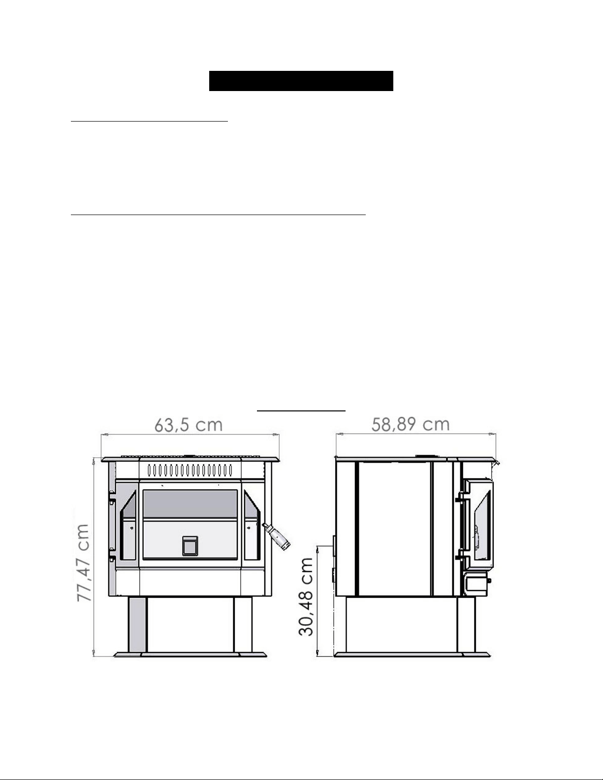
5
IMPORTANT! LISEZ ET SUIVEZ TOUTES LES INSTRUCTIONS POUR L’INSTALLATION ET L’ENTRETIEN,
NOTAMMENT CELLES PORTANT SUR LE NETTOYAGE DU POÊLE À EFFECTUER SELON LES DIRECTIVES ET
CELLES PORTANT SUR LE REMPLACEMENT DES JOINTS (ANNUELLEMENT) ET DES PIÈCES (AU BESOIN).
ENGLAND’S STOVE WORKS N’EST PAS RESPONSABLE DES DOMMAGES NI DES BLESSURES, QUELS QU’ILS SOIENT,
SUBIS EN RAISON DE NÉGLIGENCE OU À CAUSE D’UNE INSTALLATION OU D’UNE UTILISATION DANGEREUSE
DE CE PRODUIT. POUR TOUTE QUESTION, COMMUNIQUEZ AVEC LE SERVICE DE SOUTIEN TECHNIQUE.
CARACTÉRISTIQUES
Caractéristiques de chauffage
Plage de l’apport de chaleur** ....................................... 7 918 BTU/h – 15 318 BTU/h
Taux approximatif de combustion des granules** ............................................ 3,7 lb/h
Temps de combustion maximum** ................................................................. 30 heures
Surface chauffée approximative*** ..................................................... 74 m2 – 186 m2
Capacité de la trémie .............................................................................................. 45 lb
Conformité aux normes de sécurité et à celles de l’EPA
Conformité aux normes de l’EPA ……………………… ................ Certifié conforme aux
normes de 2020 sur les émissions de particules lors de l’utilisation de granules de bois.
Norme d’essai des États-Unis : règlement 40 CFR de l’EPA des États-Unis,
article 60, alinéa 60.536
Émissions de particules ................................................................................... 1,030 g/h
Efficacité* .............................................................................................................. 63 %
Testé selon les normes ..........................................UL 1482, ULC S627, ASTM E 1509
* Résultats PCS global.
** L’apport de chaleur, le taux de combustion et le temps de combustion maximum dépendent grandement du type de
granules utilisé, et ces valeurs sont donc sujettes à variation.
*** La capacité maximale de chauffage de cet appareil peut varier considérablement selon le climat, le type de construction,
l’isolation et de nombreux autres facteurs. Combinez les renseignements présentés dans ce manuel aux résultats d’un calcul
de déperdition thermique pour votre maison afin de déterminer si cet appareil suffira à combler vos besoins.
DIMENSIONS
6
IMPORTANT! LISEZ ET SUIVEZ TOUTES LES INSTRUCTIONS POUR L’INSTALLATION ET L’ENTRETIEN,
NOTAMMENT CELLES PORTANT SUR LE NETTOYAGE DU POÊLE À EFFECTUER SELON LES DIRECTIVES ET
CELLES PORTANT SUR LE REMPLACEMENT DES JOINTS (ANNUELLEMENT) ET DES PIÈCES (AU BESOIN).
ENGLAND’S STOVE WORKS N’EST PAS RESPONSABLE DES DOMMAGES NI DES BLESSURES, QUELS QU’ILS SOIENT,
SUBIS EN RAISON DE NÉGLIGENCE OU À CAUSE D’UNE INSTALLATION OU D’UNE UTILISATION DANGEREUSE
DE CE PRODUIT. POUR TOUTE QUESTION, COMMUNIQUEZ AVEC LE SERVICE DE SOUTIEN TECHNIQUE.
INSTALLATION
Vue d’ensemble de l’installation
Lorsque vous choisissez l’emplacement de votre nouveau poêle, vous devez
tenir compte d’un grand nombre de facteurs avant de commencer l’installation.
1. Habitudes de passage : afin de prévenir les accidents, le poêle doit être
installé à un endroit où il n’encombre pas le passage habituel dans la maison.
2. Flux de chaleur : tenez compte de la façon dont la chaleur circule dans votre
maison pour décider de l’endroit où vous installerez votre poêle. Installez le
poêle à l’endroit que vous avez besoin de chauffer. Souvent, une installation
en sous-sol ne permet pas qu’une chaleur suffisante atteigne les étages
supérieurs, alors qu’une installation au dernier étage ne permet pas que la
chaleur se rende aux étages inférieurs. N’oubliez pas que, tant qu’il est
chaud, l’air monte et emprunte le chemin offrant le moins de résistance.
3. Emplacement de l’évacuation : les murs extérieurs sont en général ceux
devant lesquels il convient d’installer un poêle, étant donné que l’on peut y
installer plus facilement des dispositifs d’évacuation et de prise d’air
(à l’aide de l’ensemble DuraVent AC-3000, AC-33000 au Canada).
S’il n’est pas possible d’installer le poêle devant un mur extérieur, on peut
avoir recours à des méthodes pour l’aérer en passant au travers du toit;
cependant, ces méthodes sont généralement plus coûteuses, car elles
nécessitent la pose d’un tuyau de ventilation plus long, et elles compliquent
souvent l’installation de la prise d’air.
4. Construction des murs : le fait de disposer le poêle entre les montants d’une
cloison simplifie l’installation et élimine la nécessité de restructurer le mur
pour y poser le coupe-feu mural.
AVERTISSEMENT
Ne stockez pas et n’utilisez pas d’essence ni toute autre vapeur ou liquide
inflammable à proximité de cet appareil ou de tout autre appareil.
Ne pas surchauffer : si des pièces extérieures commencent à rougeoyer,
cela veut dire que le poêle surchauffe. Réduisez l’alimentation. Le fait de
surchauffer le poêle annulera votre garantie.
Respectez les indications relatives à la distance minimale avec les matières
combustibles. Le non-respect de ces exigences pourrait provoquer un incendie.
Testé et approuvé pour des granules de bois uniquement. L’utilisation de
tout autre combustible annulera votre
g
arantie.
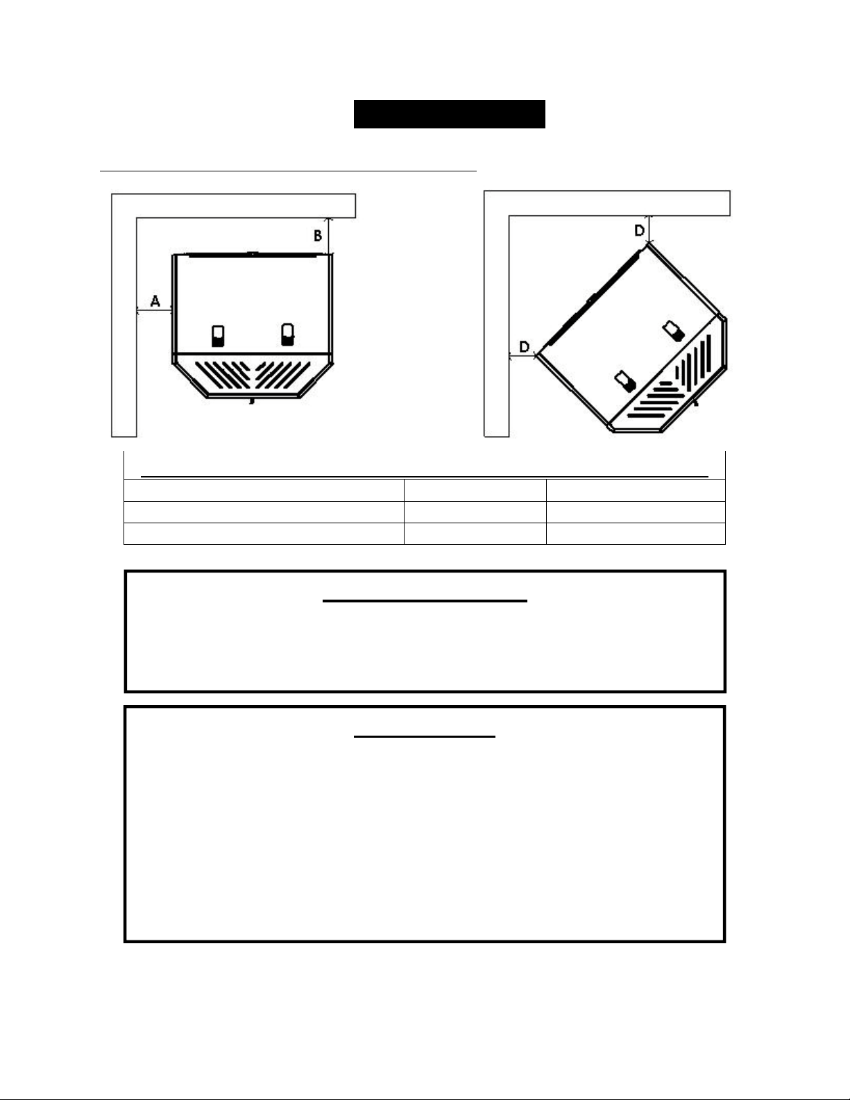
7
IMPORTANT! LISEZ ET SUIVEZ TOUTES LES INSTRUCTIONS POUR L’INSTALLATION ET L’ENTRETIEN,
NOTAMMENT CELLES PORTANT SUR LE NETTOYAGE DU POÊLE À EFFECTUER SELON LES DIRECTIVES ET
CELLES PORTANT SUR LE REMPLACEMENT DES JOINTS (ANNUELLEMENT) ET DES PIÈCES (AU BESOIN).
ENGLAND’S STOVE WORKS N’EST PAS RESPONSABLE DES DOMMAGES NI DES BLESSURES, QUELS QU’ILS SOIENT,
SUBIS EN RAISON DE NÉGLIGENCE OU À CAUSE D’UNE INSTALLATION OU D’UNE UTILISATION DANGEREUSE
DE CE PRODUIT. POUR TOUTE QUESTION, COMMUNIQUEZ AVEC LE SERVICE DE SOUTIEN TECHNIQUE.
INSTALLATION
Distance minimale avec les matières combustibles
Distanceminimaleentrel’appareiletlesmatièrescombustibles
Côté(A) Arrière (B) Coin(D)
15,24cm 15,24cm 15,24cm
6po 6po 6po
Remarque : Un dégagement de 15,24 cm facilite également le nettoyage et l’entretien
AVERTISSEMENT
INSTALLEZ L’ÉVENT EN RESPECTANT LES DÉGAGEMENTS
INDIQUÉS PAR LE FABRICANT DE L’ÉVENT.
CHAUD! N’y touchez pas! Cela pourrait entraîner de graves brûlures ou
l’inflammation des vêtements.
La vitre et les autres surfaces sont chaudes durant le fonctionnement.
ATTENTION
Gardez les enfants à l’écart.
Surveillez les enfants qui se trouvent dans la même pièce que cet appareil.
Prévenez les enfants et les adultes des risques que représentent les températures
élevées.
N’utilisez PAS l’appareil si les barrières de protection sont ouvertes ou retirées.
Tenez les vêtements, les meubles, les rideaux et les autres matières combustibles
à bonne distance.
L’installation DOIT être conforme aux codes et aux règlements municipaux,
régionaux, provinciaux et nationaux.
Consultez les autorités locales en matière de construction, le service d’incendie
ou les organismes de contrôle locaux à propos des restrictions, de l’inspection des
installations et de l’obtention de
p
ermis.

8
IMPORTANT! LISEZ ET SUIVEZ TOUTES LES INSTRUCTIONS POUR L’INSTALLATION ET L’ENTRETIEN,
NOTAMMENT CELLES PORTANT SUR LE NETTOYAGE DU POÊLE À EFFECTUER SELON LES DIRECTIVES ET
CELLES PORTANT SUR LE REMPLACEMENT DES JOINTS (ANNUELLEMENT) ET DES PIÈCES (AU BESOIN).
ENGLAND’S STOVE WORKS N’EST PAS RESPONSABLE DES DOMMAGES NI DES BLESSURES, QUELS QU’ILS SOIENT,
SUBIS EN RAISON DE NÉGLIGENCE OU À CAUSE D’UNE INSTALLATION OU D’UNE UTILISATION DANGEREUSE
DE CE PRODUIT. POUR TOUTE QUESTION, COMMUNIQUEZ AVEC LE SERVICE DE SOUTIEN TECHNIQUE.
INSTALLATION
Introduction à la ventilation
Ce poêle à granules utilise un système à tirage négatif qui tire l’air de combustion au
travers du pot de combustion et pousse l’air vicié dans le tuyau de ventilation, puis à l’extérieur
du bâtiment. Cet appareil doit être installé conformément aux techniques de ventilation décrites
en détail ci-après. Le non-respect des détails mentionnés pourrait réduire son rendement et causer
des dommages matériels, des blessures ou la mort. England’s Stove Works n’est pas responsable
des dommages causés par une installation incorrecte ou non sécuritaire.
Notre service de soutien technique est joignable au 1 800 245-6489 pour répondre aux
questions relatives à l’installation sécuritaire du poêle. Communiquez avec un agent responsable
local afin de vous assurer que l’installation est conforme aux exigences municipales et nationales
en matière de prévention des incendies. Si vous n’êtes pas certain de pouvoir installer le poêle de
façon sécuritaire, nous vous suggérons fortement de faire appel à un installateur local certifié par
le NFI (National Fireplace Institute des États-Unis).
Consignes pour la ventilation
Installez TOUJOURS le tuyau de ventilation en respectant rigoureusement les
instructions et les indications de dégagement qui accompagnent le système de
ventilation.
NE RACCORDEZ PAS le poêle à granules à un conduit de fumée déjà utilisé
pour un autre appareil.
N’INSTALLEZ PAS de régulateur de tirage, ni aucun autre dispositif de réglage
dans le système d’évacuation par ventilation de cet appareil.
UTILISEZ un manchon d’emboîtement mural homologué pour traverser un mur
et un support de plafond ou un coupe-feu pour traverser un plafond.
UTILISEZ UNIQUEMENT des tuyaux de type L ou PL de 3 po ou 4 po
approuvés pour la ventilation des poêles à granules; N’UTILISEZ PAS de tuyaux
galvanisés ni de tuyaux de type B.
SCELLEZ chaque joint de l’évent avec de la silicone résistant aux températures
élevées (pièce # AC-RTV3) afin d’éviter que la fumée se répande dans la maison.
ÉVITEZ de trop nombreux coudes et parcours horizontaux, car ils réduiront le
tirage du système de ventilation, ce qui nuira au rendement du poêle.
DISPOSEZ autant que possible le tuyau à la verticale afin d’éviter que la fumée
de l’appareil ne pénètre dans votre maison dans le cas d’une panne d’électricité.
INSPECTEZ souvent le système de ventilation afin de vous assurer qu’il n’est
pas engorgé par des cendres volantes ou par quoi que ce soit d’autre.
NETTOYEZ le système de ventilation comme l’indique la section sur l’entretien
du présent guide.
AVERTISSEMENT : Les surfaces du système de ventilation deviennent
CHAUDES et peuvent causer des brûlures si vous les touchez. Il peut être
nécessaire d’utiliser un revêtement ou des grilles de protection incombustibles.

9
IMPORTANT! LISEZ ET SUIVEZ TOUTES LES INSTRUCTIONS POUR L’INSTALLATION ET L’ENTRETIEN,
NOTAMMENT CELLES PORTANT SUR LE NETTOYAGE DU POÊLE À EFFECTUER SELON LES DIRECTIVES ET
CELLES PORTANT SUR LE REMPLACEMENT DES JOINTS (ANNUELLEMENT) ET DES PIÈCES (AU BESOIN).
ENGLAND’S STOVE WORKS N’EST PAS RESPONSABLE DES DOMMAGES NI DES BLESSURES, QUELS QU’ILS SOIENT,
SUBIS EN RAISON DE NÉGLIGENCE OU À CAUSE D’UNE INSTALLATION OU D’UNE UTILISATION DANGEREUSE
DE CE PRODUIT. POUR TOUTE QUESTION, COMMUNIQUEZ AVEC LE SERVICE DE SOUTIEN TECHNIQUE.
INSTALLATION
Renseignements supplémentaires sur la ventilation
Ne mélangez pas et n’associez pas de pièces provenant de différents fabricants
lorsque vous installez le système de ventilation (par exemple, n’utilisez PAS
le tuyau d’un fabricant avec la gaine pour tuyau d’un autre fabricant).
Il est nécessaire que le tuyau soit disposé verticalement sur au moins 0,91 m (3 pi)
pour créer un tirage naturel dans le système. Ceci facilitera l’évacuation de la
fumée du poêle dans le cas d’une coupure d’électricité ou d’une panne du
ventilateur de combustion.
Les systèmes de ventilation longs de 4,57 m ou moins devraient être composés
intégralement de tuyaux pour poêle à granules de 3 po afin de réduire les pertes
attribuables à la friction. Les systèmes plus longs, quant à eux, doivent être
composés de tuyaux pour poêle à granules de 4 po.
Ne faites pas aboutir le système de ventilation directement sous une structure
combustible comme un porche ou une terrasse.
Respectez les normes NFPA 211 énumérées ci-dessous, relatives à l’emplacement
de la terminaison des systèmes de ventilation en fonction de l’emplacement
des fenêtres et des autres ouvertures d’une résidence (reportez-vous également
à « Dégagements des terminaisons des évents »).
o NFPA 211 (version 2006) Section 10.4 Terminaison : 10.4.5 (1) L’extrémité
de sortie des systèmes mécaniques de tirage autres que les dispositifs de
ventilation directe (dispositifs pour des appareils à combustion étanche)
doit être située conformément aux indications suivantes :
(a) À au moins 0,91 m (3 pi) au-dessus de toute prise d’air par
ventilation forcée située dans un rayon de 3,04 m (10 pi).
(b) À au moins 1,21 m (4 pi) en dessous, 1,21 m. (4 pi) latéralement
et 0,3 m (1 pi) au-dessus de toute porte, fenêtre ou prise d’air par
gravité d’un bâtiment.
(c) À au moins 0,6 m (2 pi) d’un bâtiment voisin et à au moins
2,13 m (7 pi) au-dessus du trottoir lorsqu’elle jouxte la voie publique.
La hauteur de l’ouverture par rapport au niveau du sol à son aplomb doit être d’au
moins 60,96 cm (24 po). Lorsque vous mesurez la hauteur de la terminaison, prenez
en compte la hauteur habituelle des bancs de neige et la présence d’éléments
combustibles comme les tas d’herbes ou de feuilles. Dans les régions où des chutes
de neige importantes sont possibles, la hauteur de la terminaison doit être suffisante
pour que cette dernière ne soit pas obstruée par les accumulations de neige.
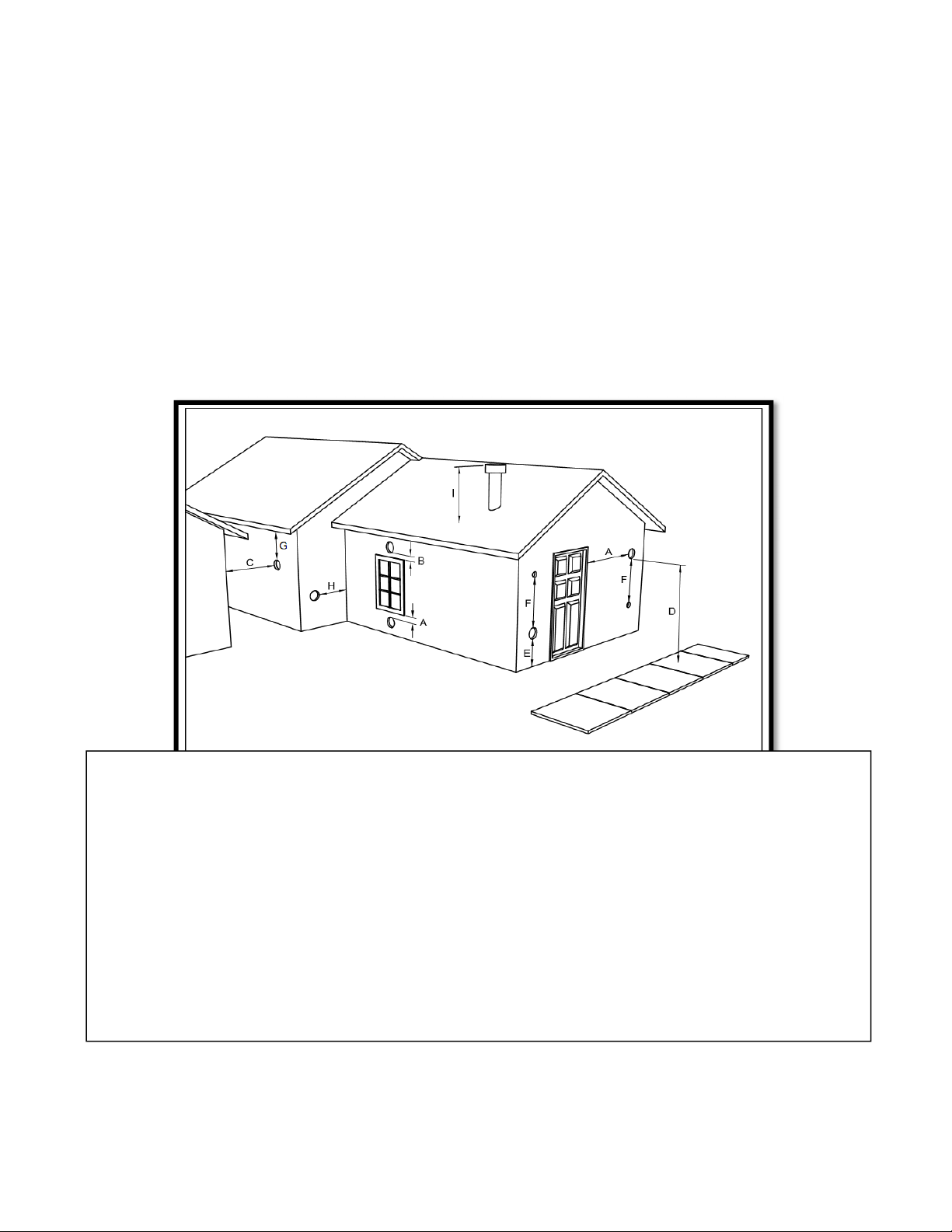
10
IMPORTANT! LISEZ ET SUIVEZ TOUTES LES INSTRUCTIONS POUR L’INSTALLATION ET L’ENTRETIEN,
NOTAMMENT CELLES PORTANT SUR LE NETTOYAGE DU POÊLE À EFFECTUER SELON LES DIRECTIVES ET
CELLES PORTANT SUR LE REMPLACEMENT DES JOINTS (ANNUELLEMENT) ET DES PIÈCES (AU BESOIN).
ENGLAND’S STOVE WORKS N’EST PAS RESPONSABLE DES DOMMAGES NI DES BLESSURES, QUELS QU’ILS SOIENT,
SUBIS EN RAISON DE NÉGLIGENCE OU À CAUSE D’UNE INSTALLATION OU D’UNE UTILISATION DANGEREUSE
DE CE PRODUIT. POUR TOUTE QUESTION, COMMUNIQUEZ AVEC LE SERVICE DE SOUTIEN TECHNIQUE.
DÉGAGEMENTS DES TERMINAISONS DES ÉVENTS
A) DÉGAGEMENT D’AU MOINS 1,21 M EN DESSOUS OU SUR LE CÔTÉ DE TOUTE PORTE OU FENÊTRE
POUVANT S’OUVRIR.
B) DÉGAGEMENT D’AU MOINS 0,3 M AU-DESSUS DE TOUTE PORTE OU FENÊTRE POUVANT S’OUVRIR.
C) DÉGAGEMENT D’AU MOINS 0,6 M DE TOUT BÂTIMENT VOISIN.
D) DÉGAGEMENT D’AU MOINS 2,13 M À PARTIR DU NIVEAU DU SOL LORSQUE L’INSTALLATION
JOUXTE LA VOIE PUBLIQUE.
E) DÉGAGEMENT D’AU MOINS 0,6 M AU-DESSUS DES HERBES, DES PLANTES ET DE TOUT AUTRE
MATÉRIAU COMBUSTIBLE.
F) DÉGAGEMENT D’AU MOINS 0,91 M DE LA PRISE D’AIR PAR VENTILATION FORCÉE D’UN APPAREIL,
QUEL QU’IL SOIT.
G) DÉGAGEMENT D’AU MOINS 0,6 M EN DESSOUS DES AVANT-TOITS OU DES SAILLIES.
H) DÉGAGEMENT D’AU MOINS 0,3 M DES MURS FAIT DE MATÉRIAUX COMBUSTIBLES.
I) LA SORTIE D’ÉVACUATION D’UN SYSTÈME DE VENTILATION COMPORTANT DES ASPIRATEURS
MÉCANIQUES DOIT DÉPASSER D’AU MOINS 30,48 CM (12 PO) LA ZONE OÙ CE SYSTÈME DE
VENTILATION TRAVERSE LE TOIT.
Remarques sur la terminaison du tu
y
au de ventilation pour poêle à
g
ranules tirées de la norme NFPA 211 (version 2006)
Section 10.4 Terminaison : 10.4.5
(Reportez-vous également à la section « INSTALLATION » du présent guide ET aux remarques supplémentaires ci-dessus) :
1.
Au moins à 0,91 m au-dessus de toute prise d’air par ventilation forcée située dans un rayon de 3,04 m.
2.
Au moins à 1,21 m en dessous, 1,21 m latéralement et 0,3 m au-dessus de toute porte, fenêtre ou prise d’air
par gravité d’un bâtiment.
3.
Au moins à 0,6 m d’un bâtiment adjacent et au moins à 2,13 m au-dessus du sol si elle jouxte la voie publique.
La sortie d’air doit être disposée de façon à ce que le flux des gaz de combustion n’affecte pas les gens, ne
surchauffe pas les structures combustibles et ne s’infiltre pas dans les bâtiments. Les systèmes de tirage forcé et
toutes les pièces des systèmes de tirage par aspiration sous pression positive pendant l’utilisation doivent être
installés de façon hermétique pour prévenir toute fuite de produits de combustion dans un bâtiment. Les sorties
d’évacuation qui passent à travers le mur ne doivent pas terminer près de la voie publique ou à un endroit où la
condensation ou la vapeur pourrait représenter une nuisance ou un danger.
Assurez-vous de respecter les règlements locaux et toutes les instructions du fabricant des produits utilisés
(y compris le tuyau d’évacuation). Si vous avez des questions, consultez un installateur professionnel ou
communiquez avec le service de soutien technique.
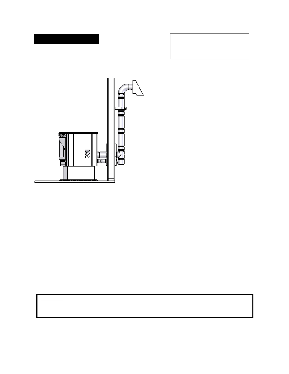
11
IMPORTANT! LISEZ ET SUIVEZ TOUTES LES INSTRUCTIONS POUR L’INSTALLATION ET L’ENTRETIEN,
NOTAMMENT CELLES PORTANT SUR LE NETTOYAGE DU POÊLE À EFFECTUER SELON LES DIRECTIVES ET
CELLES PORTANT SUR LE REMPLACEMENT DES JOINTS (ANNUELLEMENT) ET DES PIÈCES (AU BESOIN).
ENGLAND’S STOVE WORKS N’EST PAS RESPONSABLE DES DOMMAGES NI DES BLESSURES, QUELS QU’ILS SOIENT,
SUBIS EN RAISON DE NÉGLIGENCE OU À CAUSE D’UNE INSTALLATION OU D’UNE UTILISATION DANGEREUSE
DE CE PRODUIT. POUR TOUTE QUESTION, COMMUNIQUEZ AVEC LE SERVICE DE SOUTIEN TECHNIQUE.
INSTALLATION
Méthode de ventilation approuvée 1 : À travers le mur
Il s’agit en général de la méthode la plus simple.
L’installation à travers le mur à l’aide de notre
ensemble AC-3000 ou AC-33000 au Canada
(ou d’un système de ventilation similaire) est celle
que nous préconisons. Cette méthode permet de
réduire au minimum la longueur de tuyau disposé
horizontalement, de placer le poêle à proximité
d’un mur et de laisser le regard du raccord en T à
l’extérieur de la maison pour faciliter le nettoyage.
Lorsque vous installez un système de ventilation,
des tuyaux de type L ou de type PL doivent être
utilisés, et toutes les distances minimales avec les
matières combustibles (dont la liste est dressée
par le fabricant des tuyaux) doivent être
rigoureusement respectées.
Utilisez un coupe-feu mural approuvé par le
fabricant du tuyau lorsque ce dernier traverse un
mur fait de matériaux combustibles, et respectez
les distances minimales avec les matières
combustibles.
Utilisez une buse à l’endroit où l’évent est raccordé à la bouche d’évacuation du poêle à granules,
et fixez cette buse à l’aide de trois vis à tôle.
Fixez l’évent à l’extérieur de la maison à l’aide d’une courroie de mur, juste en dessous du coude
à 90 degrés.
Scellez chaque raccord de tuyau avec de la silicone résistant aux variations de température ainsi
qu’aux températures élevées afin de vous assurer que le système est exempt de fuites (consultez
les indications du fabricant du système de ventilation avant de procéder à cette opération).
Si le tuyau de ventilation utilisé n’est pas doté d’un système de verrouillage par rotation, vous aurez
besoin de trois (3) vis à tôle pour chaque joint du tuyau.
Raccordez le poêle à granules à l’air de combustion extérieur à l’aide de l’ensemble fourni avec
votre poêle, ou en suivant une autre méthode, comme le décrit la section « Raccord à l’air extérieur »,
à la page 15.
L’installation peut être adaptée pour les sous-sols (les installations en sous-sol doivent toujours
être effectuées par un installateur professionnel) ou pour d’autres cas de figure pour lesquels le
raccord en T et la partie verticale du tuyau se trouvent à l’intérieur de la maison, et le système de
ventilation passe horizontalement au travers du coupe-feu mural avant de s’arrêter.
Veuillez noter :
Les schémas d’installation sont fournis à titre de référence uniquement et ne sont pas à l’échelle. Ils ne sont pas destinés à être utilisés
comme des plans universels d’installation. Veuillez respecter toutes les exigences relatives au système de ventilation et aux distances
minimales nécessaires avec les matières combustibles, et suivre tous les codes locaux.
Pour les installations en altitude
(plus haut que 1219,2 m), le tuyau
de ventilation doit être de 4 po
plutôt que de 3 po.
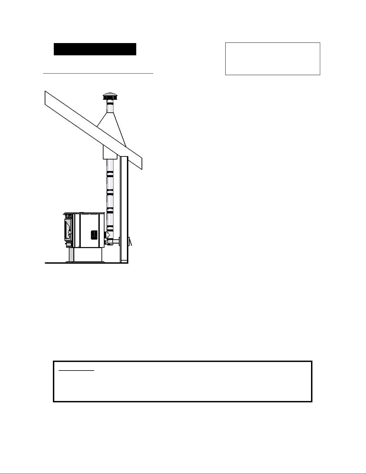
12
IMPORTANT! LISEZ ET SUIVEZ TOUTES LES INSTRUCTIONS POUR L’INSTALLATION ET L’ENTRETIEN,
NOTAMMENT CELLES PORTANT SUR LE NETTOYAGE DU POÊLE À EFFECTUER SELON LES DIRECTIVES ET
CELLES PORTANT SUR LE REMPLACEMENT DES JOINTS (ANNUELLEMENT) ET DES PIÈCES (AU BESOIN).
ENGLAND’S STOVE WORKS N’EST PAS RESPONSABLE DES DOMMAGES NI DES BLESSURES, QUELS QU’ILS SOIENT,
SUBIS EN RAISON DE NÉGLIGENCE OU À CAUSE D’UNE INSTALLATION OU D’UNE UTILISATION DANGEREUSE
DE CE PRODUIT. POUR TOUTE QUESTION, COMMUNIQUEZ AVEC LE SERVICE DE SOUTIEN TECHNIQUE.
INSTALLATION
Méthode de ventilation approuvée 2 : À travers le plafond
Il se peut que la ventilation au travers du plafond et du toit soit
la seule option envisageable dans certains cas. Ce type
d’installation est préconisé pour les usines.
Lorsque vous installez un système de ventilation, des tuyaux de
type L ou de type PL doivent être utilisés, et toutes
les distances minimales avec les matières combustibles dont
la liste est dressée par le fabricant des tuyaux doivent être
rigoureusement respectées.
Utilisez le support de plafond approuvé par le fabricant
du tuyau pour faire passer ce dernier au travers d’un plafond
fait de matériaux combustibles. Il en va de même pour le
coupe-feu, l’écran antirayonnement, le solin et la mitre.
Assurez-vous de bien suivre les indications du fabricant
relatives à la hauteur de la terminaison par rapport à la ligne
de toiture, et respectez les distances minimales avec les
matières combustibles.
Utilisez une buse à l’endroit où l’évent est raccordé à la bouche
d’évacuation du poêle à granules, et fixez cette buse à l’aide de
trois vis à tôle.
Scellez chaque raccord de tuyau avec de la silicone résistant aux
variations de température ainsi qu’aux températures élevées afin
de vous assurer que le système est exempt de fuites (consultez
les indications du fabricant du tuyau avant de procéder à cette
opération).
Si le tuyau de ventilation utilisé n’est pas doté d’un système de verrouillage par rotation, vous aurez
besoin de trois (3) vis à tôle pour chaque joint du tuyau.
Raccordez le poêle à granules à l’air de combustion extérieur à l’aide de l’ensemble fourni avec
votre poêle, ou en suivant une autre méthode, comme le décrit la section « Raccord à l’air extérieur »,
à la page 15.
Cette méthode de ventilation peut être adaptée de telle sorte que le tuyau de ventilation sorte du poêle
et traverse un mur horizontalement, avant de se diriger verticalement vers le toit au-dessus duquel
il terminera sa course. Si vous choisissez cette option d’installation, suivez attentivement les
instructions fournies par le fabricant du système de ventilation.
Pour les installations en altitude
(plus haut que 1219,2 m), le
tuyau de ventilation doit être
de 4 po plutôt que de 3 po.
Veuillez noter :
Les schémas d’installation sont fournis à titre de référence uniquement et ne sont pas à l’échelle.
Ils ne sont pas destinés à être utilisés comme des plans universels d’installation. Veuillez respecter
toutes les exigences relatives au système de ventilation et aux distances minimales nécessaires avec
les matières combustibles, et suivre tous les codes locaux.
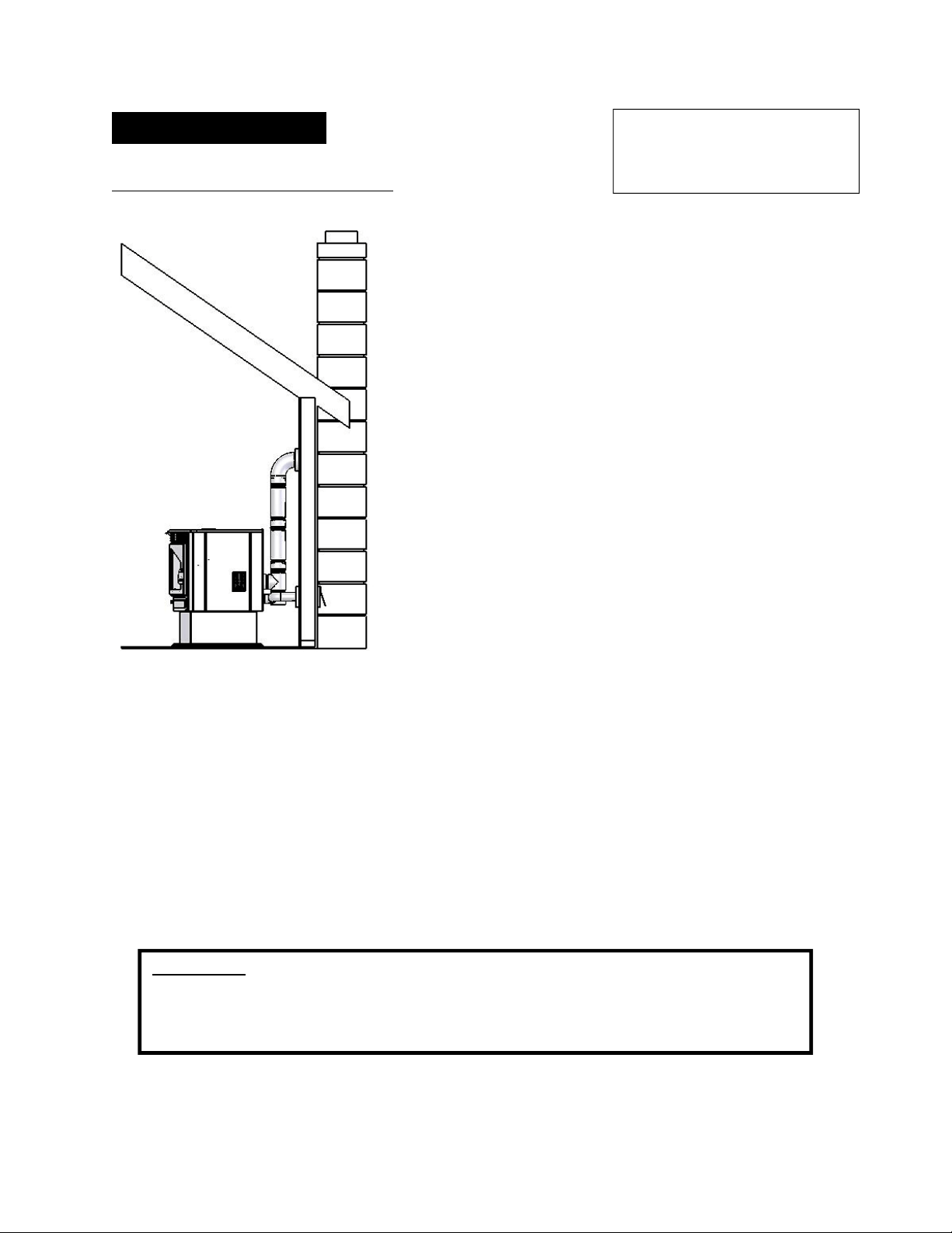
13
IMPORTANT! LISEZ ET SUIVEZ TOUTES LES INSTRUCTIONS POUR L’INSTALLATION ET L’ENTRETIEN,
NOTAMMENT CELLES PORTANT SUR LE NETTOYAGE DU POÊLE À EFFECTUER SELON LES DIRECTIVES ET
CELLES PORTANT SUR LE REMPLACEMENT DES JOINTS (ANNUELLEMENT) ET DES PIÈCES (AU BESOIN).
ENGLAND’S STOVE WORKS N’EST PAS RESPONSABLE DES DOMMAGES NI DES BLESSURES, QUELS QU’ILS SOIENT,
SUBIS EN RAISON DE NÉGLIGENCE OU À CAUSE D’UNE INSTALLATION OU D’UNE UTILISATION DANGEREUSE
DE CE PRODUIT. POUR TOUTE QUESTION, COMMUNIQUEZ AVEC LE SERVICE DE SOUTIEN TECHNIQUE.
INSTALLATION
Méthode de ventilation approuvée 3 : Système utilisant une
cheminée existante
L’utilisation d’une cheminée existante en maçonnerie
ou préfabriquée constitue la seule autre option acceptable
pour la ventilation de cet appareil à granules.
Utilisez des tuyaux de ventilation de type L ou de type PL
jusqu’à l’entrée de la cheminée existante. Utilisez un adaptateur
de dimension appropriée pour assurer la transition entre le tuyau
de ventilation du poêle et la virole de la cheminée en maçonnerie
ou préfabriquée, et assurez-vous que cet adaptateur est bien
scellé, tant au système de ventilation du poêle qu’à la cheminée.
Avant d’utiliser une cheminée existante, assurez-vous
que cette dernière est en bon état (une inspection par un
ramoneur est fortement suggérée). Assurez-vous également
que la cheminée répond aux normes minimales décrites
à l’article 211 de la NFPA (un professionnel du domaine
peut vous en assurer après inspection).
Si vous raccordez le poêle à une cheminée préfabriquée, celle-
ci doit IMPÉRATIVEMENT être conforme à la norme
UL103 HT (ULC S629 au Canada) et être dotée d’un conduit
de fumée de 15,24 cm (6 po). Un raccord à un autre type
de cheminée préfabriquée pourrait avoir des conséquences
négatives sur le fonctionnement du poêle et être la cause
d’une installation dangereuse.
Dans le cas d’un raccord à une cheminée en maçonnerie, la section transversale du conduit de fumée
doit être prise en compte. Pour les cheminées dont le conduit de fumée a un diamètre supérieur à 6 po
(surface de la section de 28.27 po2), il se peut que la pose d’un doublage de cheminée approuvé pour
utilisation avec un poêle à granules soit nécessaire.
Utilisez une buse à l’endroit où l’évent est raccordé à la bouche d’évacuation du poêle à granules,
et fixez cette buse à l’aide de trois vis à tôle.
Scellez chaque raccord de tuyau avec de la silicone résistant aux variations de température ainsi
qu’aux températures élevées afin de vous assurer que le système est exempt de fuites (consultez les
indications du fabricant du tuyau avant de procéder à cette opération).
Si le tuyau de ventilation utilisé n’est pas doté d’un système de verrouillage par rotation, vous aurez
besoin de trois (3) vis à tôle pour chaque joint du tuyau.
Raccordez le poêle à granules à l’air de combustion extérieur à l’aide de l’ensemble fourni avec
votre poêle, ou en suivant une autre méthode, comme le décrit la section « Raccord à l’air extérieur »,
à la page 15.
Veuillez noter :
Les schémas d’installation sont fournis à titre de référence uniquement et ne sont pas à l’échelle.
Ils ne sont pas destinés à être utilisés comme des plans universels d’installation. Veuillez respecter
toutes les exigences relatives au système de ventilation et aux distances minimales nécessaires avec
les matières combustibles
,
et suivre tous les codes locaux.
Pour les installations en altitude
(plus haut que 1219,2 m), le
tuyau de ventilation doit être
de 4 po plutôt que de 3 po.
14
IMPORTANT! LISEZ ET SUIVEZ TOUTES LES INSTRUCTIONS POUR L’INSTALLATION ET L’ENTRETIEN,
NOTAMMENT CELLES PORTANT SUR LE NETTOYAGE DU POÊLE À EFFECTUER SELON LES DIRECTIVES ET
CELLES PORTANT SUR LE REMPLACEMENT DES JOINTS (ANNUELLEMENT) ET DES PIÈCES (AU BESOIN).
ENGLAND’S STOVE WORKS N’EST PAS RESPONSABLE DES DOMMAGES NI DES BLESSURES, QUELS QU’ILS SOIENT,
SUBIS EN RAISON DE NÉGLIGENCE OU À CAUSE D’UNE INSTALLATION OU D’UNE UTILISATION DANGEREUSE
DE CE PRODUIT. POUR TOUTE QUESTION, COMMUNIQUEZ AVEC LE SERVICE DE SOUTIEN TECHNIQUE.
INSTALLATION
Installation dans une maison mobile
Comme pour toutes les installations impliquant cet appareil, l’utilisation de l’air
comburant extérieur est obligatoire et DOIT être utilisée. Veuillez consulter la section
« Raccord à l’air extérieur » à la page 15 du présent guide pour obtenir de plus amples
renseignements sur les raccords à l’air extérieur.
Le poêle à granules DOIT être fixé au sol de la maison mobile à l’aide de tire-fond
disposés dans les trous prévus à cet effet dans la partie inférieure du socle.
Le poêle à granules DOIT être mis à la terre à l’aide d’un fil de mise à la terre en
cuivre massif de calibre 8 AWG ou l’équivalent, dont chaque extrémité est munie
d’un dispositif avec mise à la terre approuvé par le code national de l’électricité.
Observez attentivement toutes les indications relatives au dégagement mentionnées
à la section appropriée du présent guide ET respectez les exigences du fabricant du
système de ventilation concernant les distances minimales. De plus, assurez-vous que
le système de ventilation est approuvé pour une utilisation dans une maison mobile.
L’installation doit être conforme à la norme du Manufacturers Home & Safety
Standard (HUD) CFR 3280, article 24, ainsi qu’aux règlements locaux.
AVERTISSEMENT
N’INSTALLEZ PAS CET APPAREIL DANS UNE CHAMBRE À COUCHER.
ATTENTION
L’INTÉGRITÉ STRUCTURELLE DU PLANCHER, DES MURS, DU PLAFOND
ET DU TOIT DE LA MAISON PRÉFABRI
Q
UÉE DOIT ÊTRE PRÉSERVÉE.
-Les instructions qui suivent s’appliquent à toutes
les installations-
Attention
NE TIREZ JAMAIS l’air comburant extérieur :
d’une cavité d’un mur, d’un plancher ou d’un plafond;
d’un es
p
ace clos comme un
g
renier, un
g
ara
g
e ou un vide sanitaire.
Pour les installations en altitude (plus haut que 1219,2 m), le tuyau de ventilation
doit être de 4 po plutôt que de 3 po.
N’installez pas et n’utilisez pas cet appareil à l’extérieur, dans une serre ou dans
un endroit très humide.

15
IMPORTANT! LISEZ ET SUIVEZ TOUTES LES INSTRUCTIONS POUR L’INSTALLATION ET L’ENTRETIEN,
NOTAMMENT CELLES PORTANT SUR LE NETTOYAGE DU POÊLE À EFFECTUER SELON LES DIRECTIVES ET
CELLES PORTANT SUR LE REMPLACEMENT DES JOINTS (ANNUELLEMENT) ET DES PIÈCES (AU BESOIN).
ENGLAND’S STOVE WORKS N’EST PAS RESPONSABLE DES DOMMAGES NI DES BLESSURES, QUELS QU’ILS SOIENT,
SUBIS EN RAISON DE NÉGLIGENCE OU À CAUSE D’UNE INSTALLATION OU D’UNE UTILISATION DANGEREUSE
DE CE PRODUIT. POUR TOUTE QUESTION, COMMUNIQUEZ AVEC LE SERVICE DE SOUTIEN TECHNIQUE.
RACCORDEMENT À L’AIR EXTÉRIEUR
L’air de combustion utilisé par ce poêle doit provenir de l’extérieur.
Le tuyau de raccordement à l’air extérieur dépasse de la partie inférieure centrale
de l’arrière du poêle. Utilisez l’ensemble de raccordement qui accompagne votre
poêle pour raccorder celui-ci à l’air extérieur. Les instructions ainsi que toutes les
pièces nécessaires au raccordement de votre poêle à granules à l’air extérieur sont
incluses dans l’ensemble de raccordement à l’air extérieur.
S’il ne vous est pas possible d’utiliser l’ensemble de raccordement à l’air
extérieur, vous pouvez utiliser d’autres pièces à condition de respecter ce qui suit :
o Le tuyau utilisé pour le raccordement à l’air extérieur doit être en métal
d’une épaisseur d’au moins 0,0209 po (acier doux de calibre 25) et son
diamètre intérieur doit être d’approximativement 2 po.
o Tous les joints et raccords du tuyau doivent être scellés à l’aide de
colliers de serrage ou d’un autre moyen mécanique, afin que le
raccordement à l’air extérieur ne présente pas de fuites.
o Il est déconseillé d’utiliser une trop grande longueur de tuyau et
d’y former un nombre excessif de coudes. En raison de la résistance
au frottement dans le tuyau, le rendement du poêle sera réduit si le
tuyau de raccordement à l’air extérieur est trop long.
o Une grille ou un autre dispositif de protection doit être placé à l’extrémité
du tuyau de raccordement à l’air extérieur, afin d’éviter que la pluie,
des débris ou des animaux nuisibles ne pénètrent dans la tuyauterie.
o Utilisez un tuyau d’un diamètre de 3 po si la longueur du raccordement
à l’air extérieur est de plus de 1,82 m, si le raccordement présente plus
de deux (2) coudes ou si le poêle est installé dans un sous-sol.
Le raccordement à l’air extérieur doit faire l’objet d’au moins une inspection
annuelle afin de s’assurer qu’il n’est pas obstrué.
Attention
NE CAPTEZ JAMAIS l’air extérieur de combustion dans :
La cavité d’un mur, d’un plancher ou d’un plafond.
Un es
p
ace clos tel
q
u’un
g
renier, un
g
ara
g
e ou un vide sanitaire.
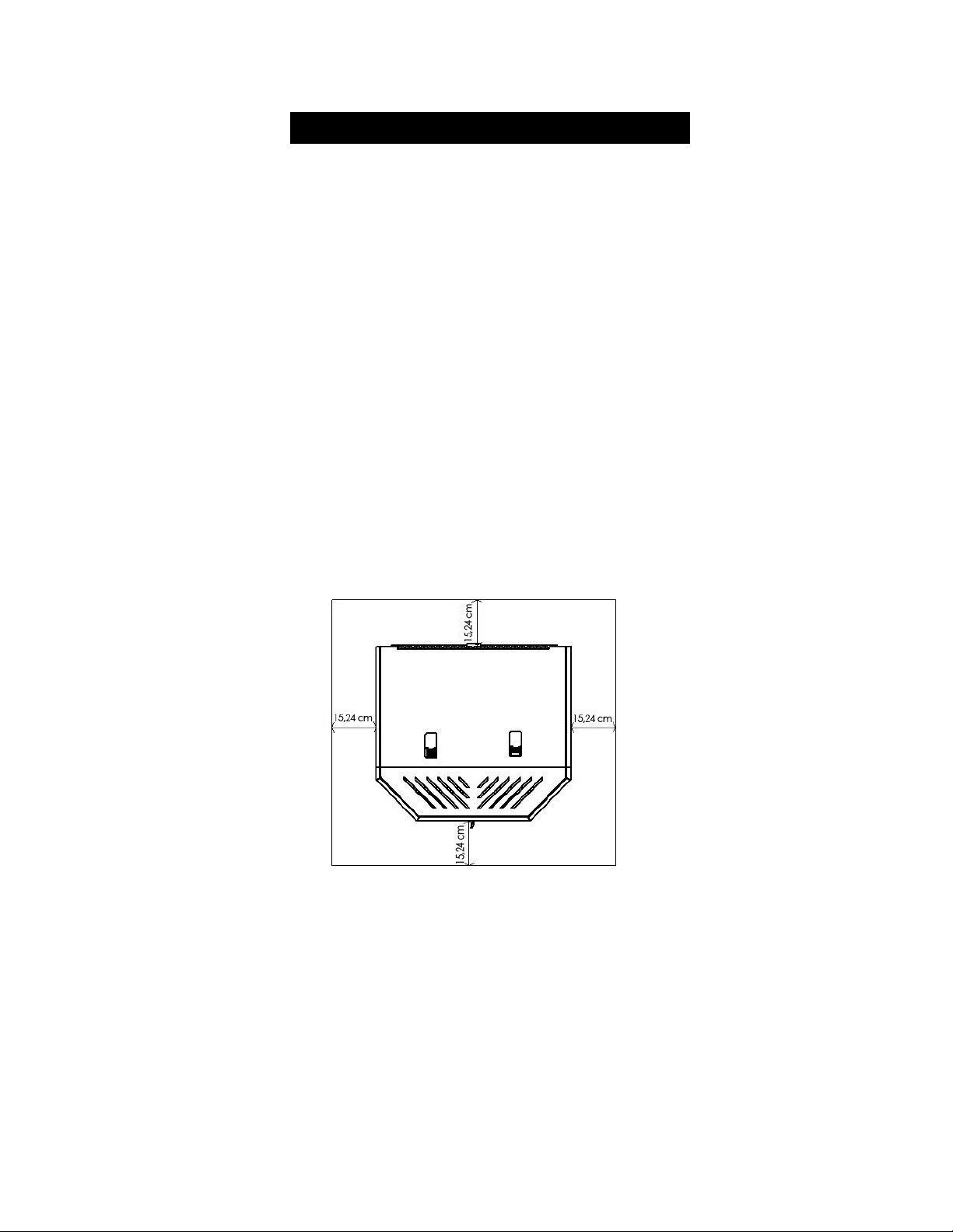
16
IMPORTANT! LISEZ ET SUIVEZ TOUTES LES INSTRUCTIONS POUR L’INSTALLATION ET L’ENTRETIEN,
NOTAMMENT CELLES PORTANT SUR LE NETTOYAGE DU POÊLE À EFFECTUER SELON LES DIRECTIVES ET
CELLES PORTANT SUR LE REMPLACEMENT DES JOINTS (ANNUELLEMENT) ET DES PIÈCES (AU BESOIN).
ENGLAND’S STOVE WORKS N’EST PAS RESPONSABLE DES DOMMAGES NI DES BLESSURES, QUELS QU’ILS SOIENT,
SUBIS EN RAISON DE NÉGLIGENCE OU À CAUSE D’UNE INSTALLATION OU D’UNE UTILISATION DANGEREUSE
DE CE PRODUIT. POUR TOUTE QUESTION, COMMUNIQUEZ AVEC LE SERVICE DE SOUTIEN TECHNIQUE.
PROTECTION DU PLANCHER
Dans le cas où le 25-CBEP est installé sur un plancher combustible, l’utilisation du
poêle nécessite la pose d’un protecteur de plancher incombustible. Si le plancher sur
lequel le poêle doit être installé est déjà incombustible (par exemple, le plancher en
béton d’un sous-sol), aucun protecteur de plancher n’est requis (vous pouvez toutefois
installer un protecteur de plancher décoratif).
Gardez à l’esprit que le poêle est non seulement lourd, mais qu’il impose également
des écarts de température au protecteur de plancher, écarts qui peuvent endommager
les carreaux, et détacher le mortier et les joints.
Le protecteur de plancher doit être homologué UL ou l’équivalent (ULC au Canada)
et doit être strictement incombustible. Étant donné que la plus grande partie de la
chaleur radiante provenant de cet appareil est dirigée vers l’avant, le protecteur de
plancher sert uniquement à empêcher les cendres et les étincelles de tomber sur le
plancher combustible près de l’appareil. Un tapis pour âtre N’EST PAS approuvé
pour remplacer une rallonge d’âtre appropriée.
États-Unis – Le protecteur de plancher doit dépasser d’au moins 15,24 cm (6 po)
à l’avant, sur les côtés et à l’arrière du poêle 25-CBEP, comme indiqué dans le
schéma ci-dessous :
Aux États-Unis, il n’est pas obligatoire que le protecteur de plancher incombustible
s’étende sous le système de ventilation, mais cela est vivement recommandé.
Au Canada, le protecteur de plancher incombustible doit être également disposé sous
tout tuyau de ventilation horizontal et dépasser de 5,08 cm (2 po) sur chacun des
côtés ET être placé directement sous tout tuyau de ventilation vertical. Au Canada,
des protections de plancher de 450 mm et de 200 mm doivent être placées
respectivement à l’avant de l’appareil et sur les côtés et à l’arrière de celui-ci.

17
IMPORTANT! LISEZ ET SUIVEZ TOUTES LES INSTRUCTIONS POUR L’INSTALLATION ET L’ENTRETIEN,
NOTAMMENT CELLES PORTANT SUR LE NETTOYAGE DU POÊLE À EFFECTUER SELON LES DIRECTIVES ET
CELLES PORTANT SUR LE REMPLACEMENT DES JOINTS (ANNUELLEMENT) ET DES PIÈCES (AU BESOIN).
ENGLAND’S STOVE WORKS N’EST PAS RESPONSABLE DES DOMMAGES NI DES BLESSURES, QUELS QU’ILS SOIENT,
SUBIS EN RAISON DE NÉGLIGENCE OU À CAUSE D’UNE INSTALLATION OU D’UNE UTILISATION DANGEREUSE
DE CE PRODUIT. POUR TOUTE QUESTION, COMMUNIQUEZ AVEC LE SERVICE DE SOUTIEN TECHNIQUE.
UTILISATION QUOTIDIENNE
Guide de démarrage
Vérifiez que la trémie est propre et ne contient pas de corps étrangers. Assurez-vous
de brancher cet appareil sur une prise de courant fonctionnelle; nous vous suggérons
d’utiliser un parasurtenseur afin de protéger ses composants électriques.
AVANT de faire le premier feu, faites fonctionner l’appareil à vide (sans mettre
de granules dans la trémie) pendant vingt minutes; pour cela, appuyez sur le bouton
« ON » (marche) après avoir branché l’appareil.
o Tout de suite après avoir appuyé sur le bouton « ON » (marche), vous
devriez entendre le ventilateur d’évacuation démarrer, puis fonctionner de
façon continue.
o Après trois à cinq minutes, cherchez à voir le rougeoiement de l’allumeur dans
le pot de combustion, afin de vous assurer qu’il fonctionne correctement.
o Abaissez manuellement l’interrupteur du couvercle de la trémie (voir le
« Schéma des pièces » de votre appareil au verso du présent guide) et vérifiez
que la vis à granules tourne bien. Relâchez l’interrupteur du couvercle de la
trémie et assurez-vous que la vis à granules arrête de tourner. NE METTEZ
PAS VOS DOIGTS DANS LA TRÉMIE ET NE LES APPROCHEZ PAS
DE LA VIS À GRANULES LORSQUE CELLE-CI EST EN ROTATION.
Après environ vingt minutes, les deux écrans d’affichage du panneau de commande
devraient afficher « E-2 » (vous trouverez de plus amples informations sur les codes
d’erreur dans la section qui traite de ce sujet dans le présent guide).
La marche à vide est alors terminée et votre appareil de chauffage à granules est prêt
à fonctionner normalement.
Allumage d’un feu
Vous devez remplir la trémie de granules de bois afin de faire fonctionner le poêle.
Soulevez le couvercle de la trémie à l’aide de la poignée encastrée et versez les
granules de bois dans la trémie.
Nous recommandons de n’utiliser que des granules fabriquées dans des
installations approuvées par le PFI (Pellet Fuel Institute). Les granules
portant le sceau d’approbation du PFI ont de faibles taux de cendres et
d’humidité, une grande valeur calorifique, et leur qualité et leur taille
sont uniformes.

18
IMPORTANT! LISEZ ET SUIVEZ TOUTES LES INSTRUCTIONS POUR L’INSTALLATION ET L’ENTRETIEN,
NOTAMMENT CELLES PORTANT SUR LE NETTOYAGE DU POÊLE À EFFECTUER SELON LES DIRECTIVES ET
CELLES PORTANT SUR LE REMPLACEMENT DES JOINTS (ANNUELLEMENT) ET DES PIÈCES (AU BESOIN).
ENGLAND’S STOVE WORKS N’EST PAS RESPONSABLE DES DOMMAGES NI DES BLESSURES, QUELS QU’ILS SOIENT,
SUBIS EN RAISON DE NÉGLIGENCE OU À CAUSE D’UNE INSTALLATION OU D’UNE UTILISATION DANGEREUSE
DE CE PRODUIT. POUR TOUTE QUESTION, COMMUNIQUEZ AVEC LE SERVICE DE SOUTIEN TECHNIQUE.
Le poêle 25-CBEP aura un aussi bon rendement avec des granules de bois de résineux
qu’avec des granules de bois de feuillus et, bien que la cendre puisse avoir un aspect
ou une texture légèrement différents, les deux types de granules brûleront proprement
et efficacement.
Le poêle 25-CBEP est doté d’un système d’allumage automatique. L’utilisateur
n’a qu’à appuyer sur le bouton « On » (marche) pour allumer le poêle.
Un court moment après que vous avez appuyé sur le bouton « On » (marche), les
lettres « S U » s’affichent sur les écrans de la plage de chaleur et de la vitesse du
ventilateur, sur le panneau de commande. Cela indique que le poêle a commencé
sa séquence de démarrage et qu’il fonctionne correctement.
Le rythme de l’alimentation en granules et la quantité d’air de combustion utilisée
au cours du démarrage sont déterminés à l’aide du panneau de commande. Le poêle
peut ainsi être réglé sur n’importe quelle plage de chaleur au démarrage. Nous
recommandons toutefois de démarrer le poêle sur la plage de chaleur 5 afin de
débuter avec un feu puissant.
Après une quinzaine de minutes, le feu devrait brûler intensément et l’indication
« S U » devrait disparaître du panneau de commande. Le poêle fonctionne alors
normalement, et les écrans d’affichage du panneau de commande restent éteints
à moins que vous ne régliez la plage de chaleur ou la vitesse du ventilateur.
Remarques à propos de l’utilisation quotidienne
Seules des granules de bois de qualité, d’un diamètre de 6,35 mm, doivent être
utilisées dans ce poêle. L’utilisation de granules de moindre qualité contenant une
grande quantité de cendres peut provoquer un engorgement plus rapide du pot de
combustion par les cendres et nécessiter un entretien périodique beaucoup plus
fréquent. Veuillez consulter la section « Entretien » du présent guide afin de mieux
comprendre en quoi le choix du combustible a une incidence sur le fonctionnement,
l’entretien et le nettoyage du poêle.
Il est normal de constater des fluctuations dans la hauteur de la flamme. En effet,
les granules de bois n’ont pas tous la même taille, ce qui peut avoir une incidence
sur l’alimentation du pot de combustion. L’intensité de la flamme peut varier
pendant le fonctionnement, mais la température de l’air d’évacuation peut rester
relativement constante sans perte de rendement.
ATTENTION
N’UTILISEZ JAMAIS D’ESSENCE, DE COMBUSTIBLE POUR LAMPE APPARENTÉ
À L’ESSENCE, DE KÉROSÈNE, DE LIQUIDE D’ALLUMAGE POUR CHARBON,
NI AUCUN LIQUIDE SIMILAIRE POUR ALLUMER OU RAVIVER UN FEU DANS CE
POÊLE. CONSERVEZ DE TELS LIQUIDES ÉLOIGNÉS DE L’APPAREIL DE CHAUFFAGE
LORSQUE CELUI-CI FONCTIONNE. DE PLUS, NE DISPOSEZ JAMAIS D’ALLUME-FEUX
SUR UNE SURFACE CHAUDE NI SUR DES TISONS DANS LE POÊLE.

19
IMPORTANT! LISEZ ET SUIVEZ TOUTES LES INSTRUCTIONS POUR L’INSTALLATION ET L’ENTRETIEN,
NOTAMMENT CELLES PORTANT SUR LE NETTOYAGE DU POÊLE À EFFECTUER SELON LES DIRECTIVES ET
CELLES PORTANT SUR LE REMPLACEMENT DES JOINTS (ANNUELLEMENT) ET DES PIÈCES (AU BESOIN).
ENGLAND’S STOVE WORKS N’EST PAS RESPONSABLE DES DOMMAGES NI DES BLESSURES, QUELS QU’ILS SOIENT,
SUBIS EN RAISON DE NÉGLIGENCE OU À CAUSE D’UNE INSTALLATION OU D’UNE UTILISATION DANGEREUSE
DE CE PRODUIT. POUR TOUTE QUESTION, COMMUNIQUEZ AVEC LE SERVICE DE SOUTIEN TECHNIQUE.
RÉGLAGES DU PANNEAU DE COMMANDE
Le panneau de commande de ce poêle vous permet de régler l’émission de chaleur et la
vitesse du ventilateur de convection, d’allumer et d’éteindre l’appareil, et de tester le bon
fonctionnement des composants (de plus amples informations sur le mode de diagnostic
vont suivre).
Les boutons au bas du panneau de commande (alimentation faible, air de combustion
faible, température de l’air entrant) ne doivent pas être utilisés au cours du
fonctionnement normal du poêle. Ces boutons sont préréglés en usine et ne doivent
pas être réglés par les utilisateurs.
Appuyez sur le bouton « On » (marche) pour allumer le poêle et démarrer un feu.
Le voyant lumineux à DEL situé au-dessus du bouton doit devenir vert et l’indication
« S U » doit s’afficher sur le panneau de commande peu de temps après.
Appuyez sur le bouton « Off » (arrêt) pour éteindre le poêle. Le voyant lumineux
situé au-dessus du bouton doit devenir rouge et l’indication « S d » doit s’afficher sur
le panneau de commande peu de temps après. La séquence d’arrêt de l’appareil débute
alors, et ce dernier reste en mode d’arrêt jusqu’à ce qu’il ait refroidi.
Pour accroître l’apport de chaleur provenant du poêle, appuyez sur la flèche orientée
vers le haut qui est associée à la plage de chaleur. La valeur affichée sur l’écran de la
plage de chaleur augmente alors, ce qui signifie que le panneau de commande règle
l’apport de chaleur en fonction de votre préférence. La vitesse du ventilateur
augmente proportionnellement à la température. Le poêle est conçu pour que la valeur
associée à la vitesse de ventilation soit toujours plus élevée ou égale à celle associée
à la plage de température. La flèche vers le bas permet de diminuer la température
ainsi que la vitesse du ventilateur.
Appuyez sur la flèche orientée vers le haut qui est associée à la vitesse du ventilateur
pour augmenter celle-ci sans augmenter la température. Appuyez jusqu’à ce que
la valeur souhaitée s’affiche à l’écran. En appuyant sur la flèche orientée vers le bas,
vous diminuerez la vitesse du ventilateur, sans toutefois que la valeur associée
à celle-ci puisse devenir inférieure à celle qui est associée à la plage de chaleur.

20
IMPORTANT! LISEZ ET SUIVEZ TOUTES LES INSTRUCTIONS POUR L’INSTALLATION ET L’ENTRETIEN,
NOTAMMENT CELLES PORTANT SUR LE NETTOYAGE DU POÊLE À EFFECTUER SELON LES DIRECTIVES ET
CELLES PORTANT SUR LE REMPLACEMENT DES JOINTS (ANNUELLEMENT) ET DES PIÈCES (AU BESOIN).
ENGLAND’S STOVE WORKS N’EST PAS RESPONSABLE DES DOMMAGES NI DES BLESSURES, QUELS QU’ILS SOIENT,
SUBIS EN RAISON DE NÉGLIGENCE OU À CAUSE D’UNE INSTALLATION OU D’UNE UTILISATION DANGEREUSE
DE CE PRODUIT. POUR TOUTE QUESTION, COMMUNIQUEZ AVEC LE SERVICE DE SOUTIEN TECHNIQUE.
CODES D’ERREUR
Les codes d’erreur ou « E-Codes » sont des codes alphanumériques qui s’affichent
sur les écrans d’affichage associés à la plage de chaleur et à la vitesse du ventilateur sur
le panneau de commande lorsque l’appareil ne fonctionne pas normalement. Ces codes
préviennent l’utilisateur que quelque chose ne fonctionne pas correctement dans le poêle
et que ce dernier doit être soigneusement inspecté avant d’être rallumé. Consultez le
guide de dépannage à la page 37 pour en savoir davantage sur les codes d’erreur.
E-0
Lorsque ce code s’affiche sur les écrans du panneau de commande
(en général, lors d’un redémarrage subséquent à un arrêt causé par un
code d’erreur), cela signifie qu’il n’y a plus d’erreur et que le poêle peut
reprendre son fonctionnement normal.
E-1
Ce code d’erreur n’est pas utilisé pour ce type de poêle. S’il s’affichait
néanmoins sur les écrans du panneau de commande, contactez le service de
soutien technique afin qu’un diagnostic puisse être établi quant à la cause de
son apparition.
E-2
Ce code indique que l’allumage des granules a échoué. Il se peut que le poêle
ait en fait allumé les granules, mais que le panneau de commande n’ait pas
détecté une température suffisamment élevée pour déterminer que le feu
a pris. Si tel est le cas, attendez que l’appareil refroidisse, nettoyez le pot de
combustion et redémarrez le poêle.
E-3
Ce code d’erreur indique que la température d’évacuation a dépassé la valeur
maximale préréglée. Le code E-3 désigne ce que l’on nomme communément
un « emballement », c’est-à-dire que l’air d’évacuation est plus chaud qu’il ne
devrait l’être.
E-4
Ce code s’affiche à la suite d’une baisse de la température de l’évacuation.
Il signifie que le feu ou que le « signal de flamme » a été perdu. Cela se
produit généralement lorsque la trémie est vide.
Si l’affichage d’un code d’erreur persiste, si un code d’erreur
semble inexplicable, ou si vous avez des questions à propos
des codes d’erreur ou de leur signification, veuillez contacter
le service de soutien techni
q
ue au 1 800 245-6489.
21
IMPORTANT! LISEZ ET SUIVEZ TOUTES LES INSTRUCTIONS POUR L’INSTALLATION ET L’ENTRETIEN,
NOTAMMENT CELLES PORTANT SUR LE NETTOYAGE DU POÊLE À EFFECTUER SELON LES DIRECTIVES ET
CELLES PORTANT SUR LE REMPLACEMENT DES JOINTS (ANNUELLEMENT) ET DES PIÈCES (AU BESOIN).
ENGLAND’S STOVE WORKS N’EST PAS RESPONSABLE DES DOMMAGES NI DES BLESSURES, QUELS QU’ILS SOIENT,
SUBIS EN RAISON DE NÉGLIGENCE OU À CAUSE D’UNE INSTALLATION OU D’UNE UTILISATION DANGEREUSE
DE CE PRODUIT. POUR TOUTE QUESTION, COMMUNIQUEZ AVEC LE SERVICE DE SOUTIEN TECHNIQUE.
PANNE D’ÉLECTRICITÉ
Si l’appareil manque d’électricité durant trois minutes ou moins, il reprendra son
fonctionnement lorsque l’alimentation électrique sera rétablie, en fonction des
indications suivantes :
État de l’appareil au moment
de la coupure d’électricité
État de l’appareil lorsque
l’alimentation est rétablie
ON (marche) Démarrage
Démarrage Démarrage
Mise hors tension Mise hors tension
OFF (arrêt) OFF (arrêt)
Si l’appareil manque d’électricité pour une durée approximative de
plus de trois minutes, il demeurera éteint lorsque l’alimentation
électrique sera rétablie.
IMPORTANT – N’ouvrez NI le couvercle de la trémie, ni la porte de
l’appareil pendant une panne d’électricité. Ouvrez la plus proche des
portes sur l’extérieur ainsi qu’une fenêtre, afin de réduire les risques
que des sous-produits de combustion s’accumulent dans la maison.
Attendez que l’alimentation électrique soit rétablie, puis appuyez sur
le bouton « ON » (marche) pour redémarrer l’appareil au besoin.
Attention – risque de choc électrique
Appuyez sur le bouton « OFF » (arrêt) et laissez l’appareil se refroidir
complètement AVANT de le débrancher et de procéder à son entretien ou au
remplacement d’une pièce.
Risque de choc électrique si l’appareil n’est pas débranché avant son entretien.
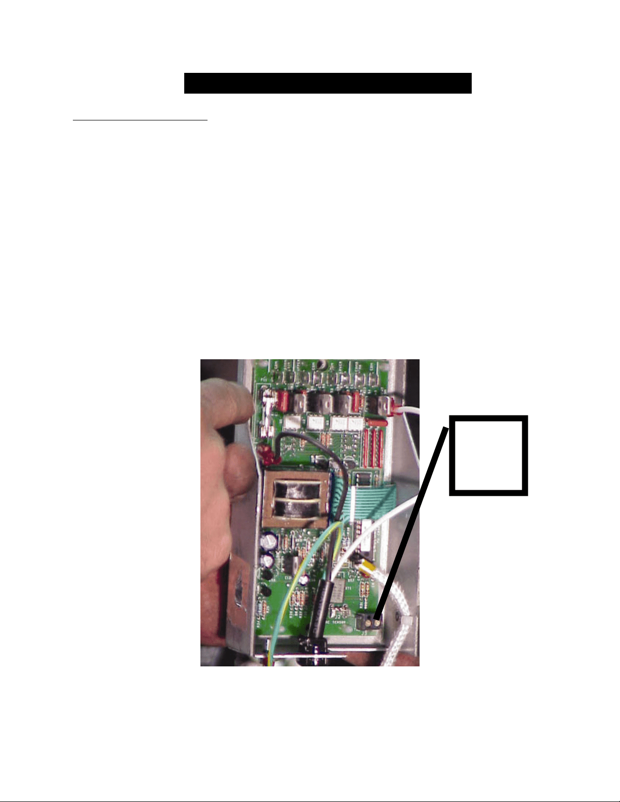
22
IMPORTANT! LISEZ ET SUIVEZ TOUTES LES INSTRUCTIONS POUR L’INSTALLATION ET L’ENTRETIEN,
NOTAMMENT CELLES PORTANT SUR LE NETTOYAGE DU POÊLE À EFFECTUER SELON LES DIRECTIVES ET
CELLES PORTANT SUR LE REMPLACEMENT DES JOINTS (ANNUELLEMENT) ET DES PIÈCES (AU BESOIN).
ENGLAND’S STOVE WORKS N’EST PAS RESPONSABLE DES DOMMAGES NI DES BLESSURES, QUELS QU’ILS SOIENT,
SUBIS EN RAISON DE NÉGLIGENCE OU À CAUSE D’UNE INSTALLATION OU D’UNE UTILISATION DANGEREUSE
DE CE PRODUIT. POUR TOUTE QUESTION, COMMUNIQUEZ AVEC LE SERVICE DE SOUTIEN TECHNIQUE.
UTILISATION DU THERMOSTAT
Installation du thermostat
1. Débranchez le poêle et retirez son panneau arrière.
2. Localisez le bloc de raccordement du thermostat, étiqueté J18, à l’arrière et vers
le bas du panneau de commande (reportez-vous à l’illustration ci-dessous ainsi
qu’à la page 44 du présent guide pour consulter un schéma du panneau de
commande). Ce bloc est doté d’un petit cavalier câblé installé en usine.
Ce cavalier permet le fonctionnement sans thermostat et doit être conservé.
3. Desserrez les deux vis à l’aide d’un petit tournevis de bijoutier à tête plate
et retirez le cavalier.
4. Insérez les deux fils du thermostat à la place du cavalier, puis resserrez les vis.
5. Réinstallez le panneau arrière et fixez le thermostat; le panneau de commande
lit automatiquement le thermostat, et votre poêle est alors prêt à l’utiliser.
Branchez
les fils du
thermostat
ici (J18)

23
IMPORTANT! LISEZ ET SUIVEZ TOUTES LES INSTRUCTIONS POUR L’INSTALLATION ET L’ENTRETIEN,
NOTAMMENT CELLES PORTANT SUR LE NETTOYAGE DU POÊLE À EFFECTUER SELON LES DIRECTIVES ET
CELLES PORTANT SUR LE REMPLACEMENT DES JOINTS (ANNUELLEMENT) ET DES PIÈCES (AU BESOIN).
ENGLAND’S STOVE WORKS N’EST PAS RESPONSABLE DES DOMMAGES NI DES BLESSURES, QUELS QU’ILS SOIENT,
SUBIS EN RAISON DE NÉGLIGENCE OU À CAUSE D’UNE INSTALLATION OU D’UNE UTILISATION DANGEREUSE
DE CE PRODUIT. POUR TOUTE QUESTION, COMMUNIQUEZ AVEC LE SERVICE DE SOUTIEN TECHNIQUE.
UTILISATION DU THERMOSTAT
Détails concernant l’utilisation du thermostat
Le poêle 25-CBEP a été conçu pour fonctionner aussi bien de façon manuelle qu’avec un
thermostat. L’utilisation du panneau de commande permet à l’utilisateur de contrôler
l’apport de chaleur provenant du poêle; le thermostat, quant à lui, permet au poêle de
démarrer ou de s’arrêter par lui-même, ce qui aide à maintenir une température constante
dans la maison et à économiser des granules de bois.
Le poêle 25-CBEP peut être connecté soit à un thermostat mural (pièce no PU-DTSTAT),
soit à un thermostat sans fil (pièce no AC-3003). Bien que le poêle fonctionne
convenablement avec les deux types de thermostat, nous suggérons fortement l’utilisation
du thermostat sans fil, parce qu’il permet de démarrer le poêle de n’importe quel endroit
de la maison.
UTILISATION DU THERMOSTAT : Ce poêle est doté d’une nouvelle fonction
exclusive qui offre deux modes de fonctionnement avec le thermostat : Le poêle sort
de l’usine préprogrammé au « mode marche/arrêt » et se met en marche ou s’éteint
en fonction de la demande de chaleur, de la même façon qu’un appareil de chauffage.
Le second mode est le « mode élevé/bas » pour lequel la combustion s’effectue en
fonction du réglage de température jusqu’à ce que l’appel de chaleur cesse. Par la suite,
le poêle continue de fonctionner avec un réglage de faible chaleur.
Pour choisir le « mode élevé /bas », débranchez l’appareil, puis rebranchez-le. Ensuite,
appuyez sur les deux flèches orientées vers le bas et relâchez-les; l’indication H L
s’affichera sur les écrans relatifs à la plage de chaleur et à la vitesse du ventilateur.
L’appareil fonctionne alors en « mode élevé/bas ». (Remarque : Répétez cette
opération pour revenir au « mode marche/arrêt ». Les écrans afficheront alors le code
0 0). L’utilisation du thermostat en « mode marche / arrêt » peut réduire la durée de vie
de l’allumeur de votre poêle.
Veuillez noter : Certains appareils pourraient ne pas répondre à cette commande. Si votre
appareil ne répond pas de cette façon, veuillez communiquer avec le service de soutien
technique au 1 800 245-6489.
Gardez à l’esprit qu’il faut placer le thermostat proche du poêle dans un emplacement
central. Si, au contraire, il est placé dans une pièce éloignée, le poêle peut surchauffer
la pièce dans laquelle il se trouve, car le thermostat ne mesurera que la température de
la pièce dans laquelle lui-même est installé.
Bien que tous les réglages de plage de chaleur et de vitesse du ventilateur soient
disponibles en mode thermostat, les deux réglages spécifiquement conçus pour celui-ci
sont les plages de chaleur 3 et 8.
o La plage de chaleur 3 est destinée à l’utilisation du thermostat dans des conditions
de fonctionnement normales.
o La plage de chaleur 8 est destinée à l’utilisation du thermostat dans les logements
spacieux ou mal isolés.
24
IMPORTANT! LISEZ ET SUIVEZ TOUTES LES INSTRUCTIONS POUR L’INSTALLATION ET L’ENTRETIEN,
NOTAMMENT CELLES PORTANT SUR LE NETTOYAGE DU POÊLE À EFFECTUER SELON LES DIRECTIVES ET
CELLES PORTANT SUR LE REMPLACEMENT DES JOINTS (ANNUELLEMENT) ET DES PIÈCES (AU BESOIN).
ENGLAND’S STOVE WORKS N’EST PAS RESPONSABLE DES DOMMAGES NI DES BLESSURES, QUELS QU’ILS SOIENT,
SUBIS EN RAISON DE NÉGLIGENCE OU À CAUSE D’UNE INSTALLATION OU D’UNE UTILISATION DANGEREUSE
DE CE PRODUIT. POUR TOUTE QUESTION, COMMUNIQUEZ AVEC LE SERVICE DE SOUTIEN TECHNIQUE.
ENTRETIEN QUOTIDIEN
Remarques importantes
Comme pour toute tâche d’entretien concernant ce produit, assurez-vous que
l’appareil est hors tension (« OFF ») et qu’il est complètement arrêté AVANT
de procéder à l’entretien.
N’oubliez pas que les pièces métalliques du foyer peuvent rester CHAUDES
longtemps après que les flammes se sont éteintes et MÊME longtemps après
l’arrêt complet de l’appareil. Soyez toujours très prudent lorsque vous manipulez
des pièces du poêle qui peuvent être chaudes, même si vous pensez qu’elles ont
refroidi.
N’enlevez les cendres que lorsque le poêle est arrêté et qu’il est refroidi
complètement. Des braises peuvent rester chaudes sous les cendres longtemps
après que le feu s’est éteint dans ce poêle (comme dans tout autre appareil du
même type).
Rangez les cendres dans un conteneur en métal muni d’un couvercle étanche et ne
placez ce conteneur que sur une surface incombustible.
La quantité de cendres et de dépôts générés par les granules dans le pot de
combustion peut varier. Surveillez attentivement l’accumulation de cendres dans
le poêle à la première utilisation et chaque fois que vous y brûlez un nouveau type
de granule.
Bien que la quantité de cendres produite par cet appareil ne soit pas très grande par
rapport à celle d’un poêle à bois traditionnel, il est ESSENTIEL que vous le
gardiez propre et exempt de cendres pour maintenir une efficacité et un rendement
optimaux. L’accumulation de cendres gêne la circulation d’air, réduit l’efficacité
et peut produire un retour de fumée.
England’s Stove Works
® n’est pas responsable des dommages, quels qu’ils soient,
subis à cause d’un poêle mal entretenu et mal nettoyé. Ce poêle à granules est un
appareil extrêmement efficace s’il reçoit l’entretien adéquat lui permettant de
maintenir un rendement optimal.
Élimination des cendres – Les cendres doivent être déposées dans un conteneur en
métal muni d’un couvercle étanche. Le contenant fermé rempli de cendres doit être
placé sur un plancher incombustible ou sur le sol, loin de tous les matériaux
combustibles, en attendant d’être éliminé définitivement. Si vous vous débarrassez des
cendres en les enterrant ou en les dispersant, vous devez d’abord les conserver dans un
contenant fermé jusqu’à ce que toutes les cendres soient complètement refroidies.
*Un mauvais netto
y
a
g
e du
p
oêle
p
eut entraîner une baisse de rendement et un retour de
f
lammes!*

25
IMPORTANT! LISEZ ET SUIVEZ TOUTES LES INSTRUCTIONS POUR L’INSTALLATION ET L’ENTRETIEN,
NOTAMMENT CELLES PORTANT SUR LE NETTOYAGE DU POÊLE À EFFECTUER SELON LES DIRECTIVES ET
CELLES PORTANT SUR LE REMPLACEMENT DES JOINTS (ANNUELLEMENT) ET DES PIÈCES (AU BESOIN).
ENGLAND’S STOVE WORKS N’EST PAS RESPONSABLE DES DOMMAGES NI DES BLESSURES, QUELS QU’ILS SOIENT,
SUBIS EN RAISON DE NÉGLIGENCE OU À CAUSE D’UNE INSTALLATION OU D’UNE UTILISATION DANGEREUSE
DE CE PRODUIT. POUR TOUTE QUESTION, COMMUNIQUEZ AVEC LE SERVICE DE SOUTIEN TECHNIQUE.
ENTRETIEN QUOTIDIEN
Retrait et élimination des cendres
Appuyez sur le bouton « OFF » (arrêt) et laissez le poêle terminer son cycle
d’arrêt et se refroidir complètement.
En raison de la conception ouverte du foyer, la majeure partie de la cendre
s’accumulera au fond du poêle. Ouvrez la porte principale du poêle et utilisez
un vieux pinceau ou un couteau à mastiquer pour dégager les cendres autour
du pot de combustion et les faire tomber dans le fond du poêle.
À l’aide d’un tournevis à manche long ou d’un couteau à mastiquer, enlevez les
dépôts qui restent dans le pot de combustion, en prenant soin de les retirer du pot
et de ne pas les laisser s’infiltrer dans le support. L’accumulation excessive de
cendres dans le support peut nuire au rendement du poêle (voir « Nettoyage du
pot de combustion » page 26).
Retirez les cendres du fond du poêle à l’aide d’une pelle ou d’un aspirateur
à cendres (de type eau et poussière) tel que notre référence AC-SV. Respectez
toutes les consignes d’utilisation de l’appareil.
Si un aspirateur de type eau et poussière est utilisé pour le nettoyage des cendres,
assurez-vous qu’il est équipé d’un filtre empêchant les fines particules de cendre
d’être soufflées dans la pièce. De même, vérifiez toujours que le poêle est
complètement froid et que TOUTES les cendres sont refroidies avant de passer
l’aspirateur.
Jetez les cendres dans un récipient métallique (comme décrit précédemment) et
conservez-les sur une surface non combustible pour permettre aux braises de se
refroidir avant de les jeter.
Le poêle est maintenant prêt à fonctionner normalement.

26
IMPORTANT! LISEZ ET SUIVEZ TOUTES LES INSTRUCTIONS POUR L’INSTALLATION ET L’ENTRETIEN,
NOTAMMENT CELLES PORTANT SUR LE NETTOYAGE DU POÊLE À EFFECTUER SELON LES DIRECTIVES ET
CELLES PORTANT SUR LE REMPLACEMENT DES JOINTS (ANNUELLEMENT) ET DES PIÈCES (AU BESOIN).
ENGLAND’S STOVE WORKS N’EST PAS RESPONSABLE DES DOMMAGES NI DES BLESSURES, QUELS QU’ILS SOIENT,
SUBIS EN RAISON DE NÉGLIGENCE OU À CAUSE D’UNE INSTALLATION OU D’UNE UTILISATION DANGEREUSE
DE CE PRODUIT. POUR TOUTE QUESTION, COMMUNIQUEZ AVEC LE SERVICE DE SOUTIEN TECHNIQUE.
ENTRETIEN QUOTIDIEN
Nettoyage du pot de combustion
Après le retrait des cendres du poêle, le nettoyage du pot de combustion est l’autre
tâche quotidienne d’entretien qui assurera le fonctionnement optimal du poêle. Les
granules contiennent des quantités variables d’impuretés et de matériaux fusibles qui
s’accumuleront dans le pot de combustion au fil du temps. Certaines granules contiennent
des quantités beaucoup plus élevées d’impuretés fusibles. Vous devez donc vous montrer
encore plus vigilant afin de garder le pot de combustion propre. Permettre aux impuretés
de s’accumuler dans le pot de combustion peut restreindre l’arrivée d’air aux flammes,
ce qui donnera lieu à une combustion sale et inefficace.
Instructions
Laissez toujours l’appareil terminer son cycle d’arrêt et se refroidir complètement
avant d’effectuer toute tâche d’entretien du foyer.
Ouvrez la porte principale du poêle et retirez le pot de combustion en le soulevant
à la verticale et en le tirant hors du support. AVERTISSEMENT – Le pot de
combustion peut rester CHAUD longtemps après que les flammes se sont éteintes;
par conséquent, vous devriez porter des gants de protection lorsque vous le
manipulez.
Une fois que vous avez retiré le pot de combustion du poêle, utilisez un tournevis
à manche long ou un couteau à mastiquer, comme mentionné précédemment, pour
enlever tous les dépôts se trouvant dans le pot.
Assurez-vous que tous les orifices d’entrée d’air sont dégagés et qu’ils ne sont pas
bouchés par des matières fusibles; un fin tournevis à pointe ou un poinçon peut
être utile pour éliminer les matières tenaces de ces orifices.
Enlevez toutes les cendres se trouvant au fond et brossez le dessus du support pour
faire tomber la cendre au fond du poêle. Il est important que vous gardiez le haut
du support libre de cendres pour que le joint avec le pot de combustion soit
parfaitement étanche.
Réinsérez le pot de combustion dans le support en suivant à l’inverse la procédure
expliquée ci-dessus.

27
IMPORTANT! LISEZ ET SUIVEZ TOUTES LES INSTRUCTIONS POUR L’INSTALLATION ET L’ENTRETIEN,
NOTAMMENT CELLES PORTANT SUR LE NETTOYAGE DU POÊLE À EFFECTUER SELON LES DIRECTIVES ET
CELLES PORTANT SUR LE REMPLACEMENT DES JOINTS (ANNUELLEMENT) ET DES PIÈCES (AU BESOIN).
ENGLAND’S STOVE WORKS N’EST PAS RESPONSABLE DES DOMMAGES NI DES BLESSURES, QUELS QU’ILS SOIENT,
SUBIS EN RAISON DE NÉGLIGENCE OU À CAUSE D’UNE INSTALLATION OU D’UNE UTILISATION DANGEREUSE
DE CE PRODUIT. POUR TOUTE QUESTION, COMMUNIQUEZ AVEC LE SERVICE DE SOUTIEN TECHNIQUE.
ENTRETIEN BIMENSUEL
Remarques importantes
Pour toute tâche d’entretien de ce produit, mettez l’appareil hors tension (« OFF »)
et attendez qu’il soit complètement arrêté et refroidi AVANT de procéder à
l’entretien.
N’oubliez pas que les pièces métalliques du foyer peuvent rester CHAUDES
longtemps après que les flammes se sont éteintes et MÊME longtemps après
l’arrêt complet de l’appareil. Soyez toujours très prudent lorsque vous manipulez
des pièces du poêle qui peuvent être chaudes, même si vous pensez qu’elles ont
refroidi.
L’entretien bimensuel comprend les étapes de la présente section AINSI QUE
les étapes de la section précédente « Entretien quotidien ».
L’usage de certaines marques de granules peut augmenter l’accumulation de
cendres derrière le couvercle de la sortie d’air et dans le tube de l’allumeur.
Un entretien attentif au cours de la première année permet de comprendre
l’emplacement des zones d’accumulation des cendres ainsi que les intervalles
nécessaires entre les nettoyages.
Bien que cette section n’en fasse pas spécifiquement mention, les joints et les
loquets de la porte principale doivent toujours être inspectés pour garantir une
bonne étanchéité. Comme indiqué précédemment, l’étanchéité à l’air de chaque
joint sur toutes les ouvertures du poêle est essentielle au bon fonctionnement de
l’appareil.
Si un aspirateur de type eau et poussière est utilisé pour le nettoyage des cendres
pendant l’entretien bimensuel, assurez-vous qu’il est équipé d’un filtre empêchant
les fines particules de cendre d’être soufflées dans la pièce. De même, vérifiez
toujours que le poêle est complètement froid et que TOUTES les cendres sont
refroidies avant de passer l’aspirateur.
Les raccords en T destinés au nettoyage et les creux des systèmes de ventilation
sont des zones sujettes à l’accumulation de cendres volantes. Veillez à inspecter
fréquemment ces zones pour détecter toute accumulation excessive de cendres.

28
IMPORTANT! LISEZ ET SUIVEZ TOUTES LES INSTRUCTIONS POUR L’INSTALLATION ET L’ENTRETIEN,
NOTAMMENT CELLES PORTANT SUR LE NETTOYAGE DU POÊLE À EFFECTUER SELON LES DIRECTIVES ET
CELLES PORTANT SUR LE REMPLACEMENT DES JOINTS (ANNUELLEMENT) ET DES PIÈCES (AU BESOIN).
ENGLAND’S STOVE WORKS N’EST PAS RESPONSABLE DES DOMMAGES NI DES BLESSURES, QUELS QU’ILS SOIENT,
SUBIS EN RAISON DE NÉGLIGENCE OU À CAUSE D’UNE INSTALLATION OU D’UNE UTILISATION DANGEREUSE
DE CE PRODUIT. POUR TOUTE QUESTION, COMMUNIQUEZ AVEC LE SERVICE DE SOUTIEN TECHNIQUE.
ENTRETIEN BIMENSUEL
Retrait et nettoyage du couvercle de la sortie d’air
Les cendres volantes s’accumulent derrière le couvercle de la sortie d’air et dans
d’autres zones non visibles.
Le couvercle de la sortie d’air sur le foyer est constitué d’une seule pièce maintenue
en place par deux (2) vis 5/16 po.
Pour retirer le couvercle de la sortie d’air, ôtez les deux (2) vis 5/16 po et soulevez
l’ensemble du couvercle pour le détacher du poêle.
o Rappel : soyez toujours très prudent lorsque vous manipulez des pièces du
poêle qui peuvent être chaudes, même si vous pensez qu’elles ont refroidi.
Une fois le couvercle de la sortie d’air retiré, la zone d’accumulation des cendres
volantes sur la tablette du foyer sera aisément repérable.
L’utilisation d’un aspirateur de type eau et poussière (ou à cendres) tel que notre
modèle AC-SV est fortement recommandée.
Nettoyage de la chambre d’évacuation
La chambre d’évacuation du poêle (visible une fois le couvercle retiré) a été
intentionnellement conçue pour accumuler les cendres. Accumuler les cendres dans
cette chambre prévient leur accumulation dans le ventilateur de combustion et le
système de ventilation.
Instructions
AVANT de passer l’aspirateur dans la chambre, vérifiez le type de cendres, ainsi
que la quantité accumulée. Les cendres accumulées dans la chambre d’évacuation
doivent être légères, moelleuses, grises ou blanches, et l’accumulation ne devrait
pas atteindre la moitié supérieure de l’orifice de nettoyage.
o Des cendres de couleur brun foncé ou noire indiquent généralement une
combustion incomplète des granules.
o Ne laissez PAS les cendres s’accumuler en hauteur dans cette zone,
car elles peuvent « étouffer » le ventilateur de combustion et nuire au
rendement du poêle.

29
IMPORTANT! LISEZ ET SUIVEZ TOUTES LES INSTRUCTIONS POUR L’INSTALLATION ET L’ENTRETIEN,
NOTAMMENT CELLES PORTANT SUR LE NETTOYAGE DU POÊLE À EFFECTUER SELON LES DIRECTIVES ET
CELLES PORTANT SUR LE REMPLACEMENT DES JOINTS (ANNUELLEMENT) ET DES PIÈCES (AU BESOIN).
ENGLAND’S STOVE WORKS N’EST PAS RESPONSABLE DES DOMMAGES NI DES BLESSURES, QUELS QU’ILS SOIENT,
SUBIS EN RAISON DE NÉGLIGENCE OU À CAUSE D’UNE INSTALLATION OU D’UNE UTILISATION DANGEREUSE
DE CE PRODUIT. POUR TOUTE QUESTION, COMMUNIQUEZ AVEC LE SERVICE DE SOUTIEN TECHNIQUE.
À l’aide d’un aspirateur de type eau et poussière, enlevez les cendres volantes
de la chambre d’évacuation comme indiqué précédemment dans ce guide.
Pour faciliter cette tâche, vous pouvez fixer un petit embout à l’extrémité du
tuyau de l’aspirateur pour atteindre les cendres difficiles d’accès.
Après avoir retiré toutes les cendres volantes derrière le couvercle et dans la zone
de la chambre d’évacuation, replacez le couvercle sur le poêle et fixez-le à l’aide
des deux (2) vis 5/16 po retirées auparavant.
Serrez les vis de façon à obtenir une étanchéité suffisante, mais sans excès pour
éviter de les endommager.
Attention
Cetappareilestconçupourfonctionneruniquementlorsquelaporteprincipale
estfermée.L’utilisationdupoêleaveclaporteouverteprovoqueraitun
refoulementdefuméeetunecombustionlenteetinefficace.
Deplus,l’utilisationdecombustiblesautresquelesgranulesdeboispeut
êtredangereuseetproduireunexcèsdemonoxyde
decarbone.Lemonoxyde
decarboneestungazmortelquiestinodoreetincolore.
UtilisezSEULEMENTdesgranulesdeboisdanslepoêle.
Détecteurdemonoxydedecarbone
England’sStoveWorks,Inc.recommandefortementl’utilisationd’undétecteur
demonoxydedecarboneàproximitédupoêleetàtouslesétagesdelamaison.
Unecertainequantitédemonoxydedecarboneestcrééedanslepoêlecommesous‐produit
decombustion.Touslesraccordsdutuyaud’évacuationdoiventêtrescellésavecdela
siliconerésistantauxvariationsdetempératureafind’obtenirunjointétanche.Toutefuitedans
unespacecloscauséeparunemauvaiseinstallationouunemauvaiseutilisationdupoêlepeut
provoquerdesétourdissementsdesnauséeset,danslescasextrêmes,lamort.Laconcentration
demonoxydedecarbonependantl’essaiétaitde0,017g/min.

30
IMPORTANT! LISEZ ET SUIVEZ TOUTES LES INSTRUCTIONS POUR L’INSTALLATION ET L’ENTRETIEN,
NOTAMMENT CELLES PORTANT SUR LE NETTOYAGE DU POÊLE À EFFECTUER SELON LES DIRECTIVES ET
CELLES PORTANT SUR LE REMPLACEMENT DES JOINTS (ANNUELLEMENT) ET DES PIÈCES (AU BESOIN).
ENGLAND’S STOVE WORKS N’EST PAS RESPONSABLE DES DOMMAGES NI DES BLESSURES, QUELS QU’ILS SOIENT,
SUBIS EN RAISON DE NÉGLIGENCE OU À CAUSE D’UNE INSTALLATION OU D’UNE UTILISATION DANGEREUSE
DE CE PRODUIT. POUR TOUTE QUESTION, COMMUNIQUEZ AVEC LE SERVICE DE SOUTIEN TECHNIQUE.
ENTRETIEN MENSUEL
Remarques importantes
Pour toute tâche d’entretien de ce produit, mettez l’appareil hors tension (« OFF »)
et attendez qu’il soit complètement arrêté et refroidi AVANT de procéder à
l’entretien.
N’oubliez pas que les pièces métalliques du foyer peuvent rester CHAUDES
longtemps après que les flammes se sont éteintes et MÊME longtemps après l’arrêt
complet de l’appareil. Soyez toujours très prudent lorsque vous manipulez des
pièces du poêle qui peuvent être chaudes, même si vous pensez qu’elles ont refroidi.
L’entretien mensuel comprend les étapes de la présente section AINSI QUE
les étapes des sections « Entretien quotidien » et « Entretien bimensuel ».
Les nettoyages mensuels peuvent s’effectuer par plus grands intervalles, selon
la durée d’utilisation quotidienne du poêle. Un poêle qui chauffe en permanence
a plus fréquemment besoin des nettoyages prévus sur une base mensuelle qu’un
poêle utilisé périodiquement comme chauffage d’appoint.
La règle à suivre est la suivante : l’entretien mensuel doit effectivement être
réalisé une fois par mois OU chaque fois qu’une tonne de granules a été brûlée
(si moins d’un mois s’est écoulé depuis le dernier entretien).
Si trop de cendre s’accumule dans la chambre d’évacuation ou dans le système
de ventilation pendant le mois, on doit réduire les intervalles entre les nettoyages
afin d’éviter que l’accumulation de cendre nuise au rendement du poêle.

31
IMPORTANT! LISEZ ET SUIVEZ TOUTES LES INSTRUCTIONS POUR L’INSTALLATION ET L’ENTRETIEN,
NOTAMMENT CELLES PORTANT SUR LE NETTOYAGE DU POÊLE À EFFECTUER SELON LES DIRECTIVES ET
CELLES PORTANT SUR LE REMPLACEMENT DES JOINTS (ANNUELLEMENT) ET DES PIÈCES (AU BESOIN).
ENGLAND’S STOVE WORKS N’EST PAS RESPONSABLE DES DOMMAGES NI DES BLESSURES, QUELS QU’ILS SOIENT,
SUBIS EN RAISON DE NÉGLIGENCE OU À CAUSE D’UNE INSTALLATION OU D’UNE UTILISATION DANGEREUSE
DE CE PRODUIT. POUR TOUTE QUESTION, COMMUNIQUEZ AVEC LE SERVICE DE SOUTIEN TECHNIQUE.
ENTRETIEN MENSUEL
Nettoyage du tuyau de ventilation
Les pièces inférieures et de raccordement du système de ventilation (comme
les tés et les coudes) constituent des zones où les cendres volantes peuvent
s’accumuler. VÉRIFIEZ soigneusement l’accumulation dans ces zones afin de
vous assurer que le système de ventilation peut fonctionner en toute sécurité.
Selon le type de système de ventilation de votre poêle, il peut être possible d’ôter
le couvercle en té des orifices de nettoyage et de simplement enlever les cendres
volantes accumulées à l’aide d’une brosse pour tuyau. Vous trouverez des brosses
spécifiquement conçues pour le nettoyage des tuyaux de poêles à granules chez le
détaillant qui vous a vendu votre poêle, ainsi que chez la plupart des revendeurs
de produits pour âtres.
Les parties horizontales des tuyaux, telles que le tuyau de raccord de l’évacuation
au tuyau vertical, accumulent les cendres volantes et doivent être inspectées
minutieusement et nettoyées à l’aide d’une brosse.
Vérifiez que les embouts ne sont pas bouchés ou obstrués par les cendres volantes
accumulées.
Après avoir soigneusement nettoyé le système de ventilation, refermez tous
les joints démontés avec de la silicone résistant aux températures élevées
(pièce nº AC-RTV3), si cela s’applique à votre système de ventilation.
Inspectez les joints qui n’ont pas été démontés pour vous assurer qu’ils sont
étanches aux fumées.
Après une utilisation prolongée du poêle, vous trouverez généralement les zones
de fuite du système de ventilation en cherchant les dépôts de cendres volantes
à l’extérieur du tuyau. Surveillez soigneusement les fuites du système de
ventilation et scellez les tuyaux en conséquence.
Bien que la plupart des systèmes de ventilation des poêles à granules soient conçus
pour durer toute une vie, les cendres volantes produites par les granules peuvent
les corroder dans certains cas. Lors du nettoyage de votre système de ventilation,
examinez attentivement les tuyaux pour détecter tout signe de détérioration, et
remplacez les pièces excessivement usées. Il est peu probable que vous ayez à
vous préoccuper de cet aspect, mais il est important de maintenir votre système de
ventilation en bon état pour garantir le fonctionnement sécuritaire de votre poêle.

32
IMPORTANT! LISEZ ET SUIVEZ TOUTES LES INSTRUCTIONS POUR L’INSTALLATION ET L’ENTRETIEN,
NOTAMMENT CELLES PORTANT SUR LE NETTOYAGE DU POÊLE À EFFECTUER SELON LES DIRECTIVES ET
CELLES PORTANT SUR LE REMPLACEMENT DES JOINTS (ANNUELLEMENT) ET DES PIÈCES (AU BESOIN).
ENGLAND’S STOVE WORKS N’EST PAS RESPONSABLE DES DOMMAGES NI DES BLESSURES, QUELS QU’ILS SOIENT,
SUBIS EN RAISON DE NÉGLIGENCE OU À CAUSE D’UNE INSTALLATION OU D’UNE UTILISATION DANGEREUSE
DE CE PRODUIT. POUR TOUTE QUESTION, COMMUNIQUEZ AVEC LE SERVICE DE SOUTIEN TECHNIQUE.
ENTRETIEN ANNUEL
Remarques importantes
Pour toute tâche d’entretien de ce produit, mettez l’appareil hors tension (« OFF »)
et attendez qu’il soit complètement arrêté et refroidi AVANT de procéder à
l’entretien.
N’oubliez pas que les pièces métalliques du foyer peuvent rester CHAUDES
longtemps après que les flammes se sont éteintes et MÊME longtemps après
l’arrêt complet de l’appareil. Soyez toujours très prudent lorsque vous manipulez
des pièces du poêle qui peuvent être chaudes, même si vous pensez qu’elles ont
refroidi.
L’entretien annuel (ou de fin de saison) comprend les étapes de la présente
section, AINSI QUE les étapes des sections « Entretien quotidien »,
« Entretien bimensuel » et « Entretien mensuel ».
Vous devez effectuer l’entretien annuel à la fin de la saison de chauffage. Laisser
les cendres et les autres matières accumulées dans le poêle pendant les mois où
on ne l’utilise pas peut causer une dégradation prématurée du métal du poêle et
du système de ventilation. Portez particulièrement attention aux détails et nettoyez
minutieusement le poêle à la fin de la saison de chauffage. Cela vous permettra
d’utiliser votre poêle et son système de ventilation longtemps.
Attention – risque de choc électrique
Appuyez sur le bouton « OFF » (arrêt) et laissez l’appareil se refroidir
complètement AVANT de le débrancher et de procéder à son entretien ou au
remplacement d’une pièce.
Risque de choc électrique si l’appareil n’est pas débranché avant son entretien.
Suie et cendres volantes : formation et retrait
Les produits de combustion contiennent des petites particules de cendres volantes.
Ces cendres volantes s’accumulent dans le système d’évacuation par ventilation
et restreignent le flux des gaz de combustion. La combustion incomplète, comme
celle qui survient lors du démarrage et de l’arrêt du poêle ou en cas de mauvais
fonctionnement du poêle, produira de la suie qui s’accumulera dans le système
d’évacuation par ventilation. Inspectez le système d’évacuation par ventilation
au moins une fois par année pour savoir s’il a besoin d’être nettoyé.

33
IMPORTANT! LISEZ ET SUIVEZ TOUTES LES INSTRUCTIONS POUR L’INSTALLATION ET L’ENTRETIEN,
NOTAMMENT CELLES PORTANT SUR LE NETTOYAGE DU POÊLE À EFFECTUER SELON LES DIRECTIVES ET
CELLES PORTANT SUR LE REMPLACEMENT DES JOINTS (ANNUELLEMENT) ET DES PIÈCES (AU BESOIN).
ENGLAND’S STOVE WORKS N’EST PAS RESPONSABLE DES DOMMAGES NI DES BLESSURES, QUELS QU’ILS SOIENT,
SUBIS EN RAISON DE NÉGLIGENCE OU À CAUSE D’UNE INSTALLATION OU D’UNE UTILISATION DANGEREUSE
DE CE PRODUIT. POUR TOUTE QUESTION, COMMUNIQUEZ AVEC LE SERVICE DE SOUTIEN TECHNIQUE.
ENTRETIEN ANNUEL
Nettoyage du ventilateur d’évacuation
Même si le ventilateur d’évacuation et son boîtier ont été conçus de façon à réduire
l’accumulation de cendres, une certaine quantité de cendres s’y accumulera pendant toute
la saison de chauffage. La quantité et le type de cendres dépendent du type de granules
et du système de ventilation, mais, en général, il y a peu d’accumulation. Si vous trouvez
une grande quantité de cendres volantes dans le ventilateur d’évacuation lors de son
nettoyage, vous devez en effectuer l’entretien tous les mois ou deux fois par mois pour
éviter une accumulation excessive.
Instructions
Avant de procéder à l’entretien du ventilateur d’évacuation, assurez-vous
que l’appareil est débranché et complètement refroidi.
Pour retirer le panneau de gauche et accéder au ventilateur d’évacuation :
o Retirez les deux vis 5/16 po qui retiennent le panneau latéral à l’arrière
de l’appareil, du côté le plus proche du ventilateur d’évacuation (à gauche
si vous êtes placé face au poêle).
o Tirez le panneau latéral vers l’arrière en le soutenant avec précaution et
éloignez-le du poêle. Le panneau latéral doit se déloger des supports à rainure.
o Une fois le panneau latéral enlevé, le ventilateur d’évacuation est clairement
visible.
Dégagez légèrement le système de ventilation du ventilateur d’évacuation de façon
à pouvoir retirer celui-ci du poêle.
Débranchez les deux fils qui relient le faisceau de câblage du poêle au ventilateur
d’évacuation à l’aide des embouts à raccord rapide.
Desserrez et retirez la vis de 5/16 po, située en haut de la bouche d’évacuation
du ventilateur, qui maintient le détecteur thermique sur ce dernier.
Dévissez les cinq (5) vis autotaraudeuses de 5/16 po qui fixent le ventilateur
d’évacuation au tube d’évacuation. L’accès aux vis inférieures est plus aisé
à travers les découpes circulaires dans le corps du poêle. Il se peut qu’une
rallonge de 30 cm (12 po) soit nécessaire pour atteindre toutes les vis.
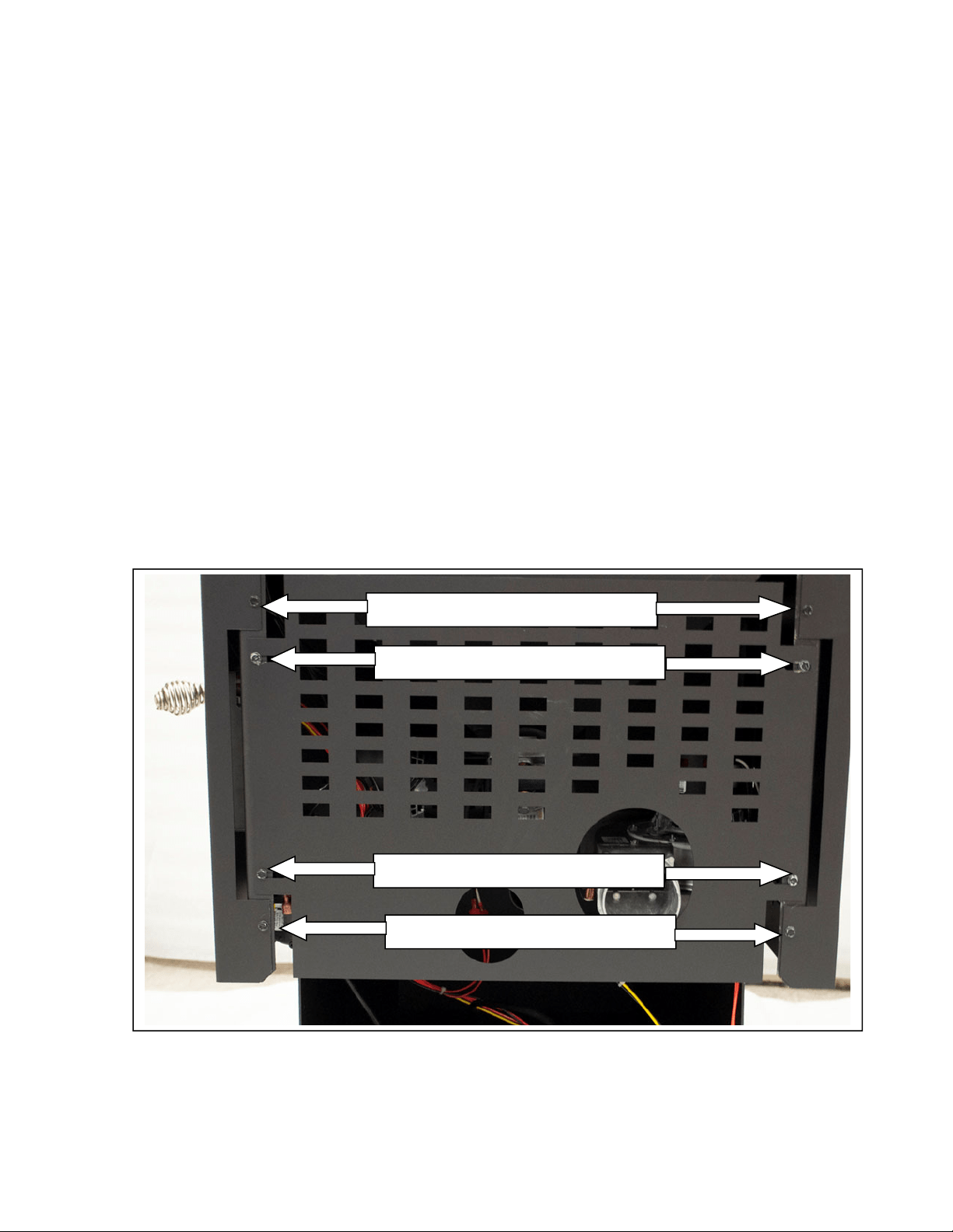
34
IMPORTANT! LISEZ ET SUIVEZ TOUTES LES INSTRUCTIONS POUR L’INSTALLATION ET L’ENTRETIEN,
NOTAMMENT CELLES PORTANT SUR LE NETTOYAGE DU POÊLE À EFFECTUER SELON LES DIRECTIVES ET
CELLES PORTANT SUR LE REMPLACEMENT DES JOINTS (ANNUELLEMENT) ET DES PIÈCES (AU BESOIN).
ENGLAND’S STOVE WORKS N’EST PAS RESPONSABLE DES DOMMAGES NI DES BLESSURES, QUELS QU’ILS SOIENT,
SUBIS EN RAISON DE NÉGLIGENCE OU À CAUSE D’UNE INSTALLATION OU D’UNE UTILISATION DANGEREUSE
DE CE PRODUIT. POUR TOUTE QUESTION, COMMUNIQUEZ AVEC LE SERVICE DE SOUTIEN TECHNIQUE.
Soulevez le ventilateur d’évacuation et retirez-le du poêle. Le joint qui scelle le
ventilateur d’évacuation au tuyau d’évacuation est fragile, alors soyez très prudent
lorsque vous retirez le ventilateur. Cependant, même en étant prudent, il est facile
de déchirer ce joint fragile et, comme l’étanchéité est essentielle à cet endroit,
il est préférable de remplacer le joint (pièce nº PU-CBMG) chaque fois que vous
enlevez le ventilateur d’évacuation.
Après avoir enlevé le ventilateur d’évacuation, nettoyez toute accumulation
de cendres dans le tuyau d’évacuation à l’aide d’un aspirateur de type eau et
poussière (ou à cendres).
Utilisez un pinceau doux pour retirer soigneusement toute accumulation de
cendres à l’intérieur du ventilateur d’évacuation et sur sa pale.
Inspectez le moteur du ventilateur d’évacuation pour trouver toute accumulation
de poussière et enlevez-la soigneusement, en vous assurant que tous les trous
de refroidissement du moteur sont dégagés et libres de dépôts de poussière.
Réinstallez le ventilateur et le panneau latéral en suivant à l’inverse les étapes
décrites précédemment. N’oubliez pas de vérifier l’état du joint d’étanchéité du
ventilateur d’évacuation ET de reconnecter le détecteur thermique au sommet
de la bouche d’évacuation du ventilateur avant de remonter le panneau latéral.
Vis du panneau latéral
Vis du
p
anneau latéral
Vis du
p
anneau arrière
Vis du
p
anneau arrière

35
IMPORTANT! LISEZ ET SUIVEZ TOUTES LES INSTRUCTIONS POUR L’INSTALLATION ET L’ENTRETIEN,
NOTAMMENT CELLES PORTANT SUR LE NETTOYAGE DU POÊLE À EFFECTUER SELON LES DIRECTIVES ET
CELLES PORTANT SUR LE REMPLACEMENT DES JOINTS (ANNUELLEMENT) ET DES PIÈCES (AU BESOIN).
ENGLAND’S STOVE WORKS N’EST PAS RESPONSABLE DES DOMMAGES NI DES BLESSURES, QUELS QU’ILS SOIENT,
SUBIS EN RAISON DE NÉGLIGENCE OU À CAUSE D’UNE INSTALLATION OU D’UNE UTILISATION DANGEREUSE
DE CE PRODUIT. POUR TOUTE QUESTION, COMMUNIQUEZ AVEC LE SERVICE DE SOUTIEN TECHNIQUE.
ENTRETIEN ANNUEL
Nettoyage du ventilateur de convection
Comme toujours, assurez-vous que le poêle est refroidi et débranché avant d’effectuer
l’entretien d’un de ses composants, quel qu’il soit. Comme le ventilateur de convection
ne traite pas les sous-produits de combustion, il ne nécessite pas un nettoyage aussi
minutieux que le ventilateur d’évacuation. Cependant, la poussière de la maison et
d’autres débris présents dans l’air peuvent s’accumuler sur les pales du ventilateur de
convection. Le ventilateur de convection est situé sur le côté du poêle, à l’opposé du
ventilateur de combustion. Une fois le panneau latéral du poêle retiré, le ventilateur de
convection doit être inspecté visuellement pour détecter toute accumulation de poussière.
En général, la poussière qui s’est accumulée sur les pales du ventilateur peut être enlevée
facilement à l’aide d’un aspirateur ou d’un pinceau doux.
Nettoyage des fines dans la trémie et la vis à granules
Selon le type et la qualité de granules brûlées dans le poêle, des fines et de la poussière
peuvent s’accumuler dans la trémie. La plupart des fines s’accumuleront dans la partie
inférieure de la vis à granules, vers l’arrière du poêle. Éteignez le poêle et débranchez-le.
Après avoir vidé la trémie, nettoyez les fines se trouvant dans le tube de la vis à granules
à l’aide d’un aspirateur eau et poussière. Si vous ne pouvez pas enlever les fines de la
partie supérieure de la trémie :
Retirez les panneaux :
o Retirez les deux panneaux latéraux en suivant la procédure décrite dans la
section « Nettoyage du ventilateur d’évacuation » à la page 33 de ce guide.
o Ensuite, ôtez le panneau arrière en retirant les quatre vis de 5/16 po qui le
retiennent et en le délogeant du poêle avec précaution. Consultez l’image
page 34.
Repérez le moteur de la vis à granules dans la partie centrale arrière du poêle,
puis repérez les deux vis de calage de chaque côté du collet de montage en fonte.
À l’aide d’une clé hexagonale de 3/16 po, desserrez les vis de calage de chaque
côté du collet de montage de la vis à granules;
en tenant l’aspirateur eau et poussière d’une main, laissez l’ensemble vis à granules
glisser légèrement de son tube, de façon à pouvoir aspirer toutes les fines se
trouvant dans cette zone;
réinstallez l’ensemble vis à granules et serrez les deux vis de calage; remontez
le panneau arrière et les deux panneaux latéraux en veillant à serrer les huit (8)
vis à l’arrière du poêle.
Reportez-vous à la page 39 pour obtenir une illustration et plus d’informations sur le
moteur de la vis à granules.

36
IMPORTANT! LISEZ ET SUIVEZ TOUTES LES INSTRUCTIONS POUR L’INSTALLATION ET L’ENTRETIEN,
NOTAMMENT CELLES PORTANT SUR LE NETTOYAGE DU POÊLE À EFFECTUER SELON LES DIRECTIVES ET
CELLES PORTANT SUR LE REMPLACEMENT DES JOINTS (ANNUELLEMENT) ET DES PIÈCES (AU BESOIN).
ENGLAND’S STOVE WORKS N’EST PAS RESPONSABLE DES DOMMAGES NI DES BLESSURES, QUELS QU’ILS SOIENT,
SUBIS EN RAISON DE NÉGLIGENCE OU À CAUSE D’UNE INSTALLATION OU D’UNE UTILISATION DANGEREUSE
DE CE PRODUIT. POUR TOUTE QUESTION, COMMUNIQUEZ AVEC LE SERVICE DE SOUTIEN TECHNIQUE.
ENTRETIEN ANNUEL
Vérification des joints
Il est essentiel que les portes et que le couvercle de la trémie soit hermétiquement
scellés pour assurer le bon fonctionnement du poêle. Une fuite d’air dans ces zones
peut causer non seulement un brûlage sale et inefficace, mais aussi représenter un risque
pour la sécurité. Pour cette raison, vous devez toujours conserver en bon état les joints
d’étanchéité et les remplacer annuellement ou plus tôt, si nécessaire. Vous pouvez
vérifier l’étanchéité des joints à l’aide de la méthode du « billet de banque » :
Glissez un billet de banque entre le joint et le corps du poêle (à l’endroit où le
joint touche au poêle).
Serrez le mécanisme de verrouillage vers le bas et essayez de retirer le billet de
banque. Si le billet de banque entre et sort facilement, vous devez remplacer le
joint d’étanchéité. Répétez ce test sur tout le périmètre du joint d’étanchéité,
car il peut être en bon état d’un côté, mais en mauvais état de l’autre.
Effectuez ce test tout autour du périmètre de la porte et du couvercle de la trémie.
Si le test est un échec pour l’une des zones, le joint d’étanchéité en entier doit être
remplacé. Le numéro de pièce du joint d’étanchéité à remplacer se trouve dans la
section « Illustration détaillée des pièces » au dos de ce guide.
Les joints d’étanchéité doivent être remplacés uniquement par des joints
d’étanchéité équivalents en fibres de verre, spécialement conçus pour cet appareil
par England’s Stove Works
®
. Les instructions de dépose et de remplacement des
joints sont fournies avec le kit de joints commandé. Elles figurent également
dans les vidéos d’instructions produites pour ce poêle (voir le DVD fourni avec
l’appareil ou rendez-vous sur youtube.com/heatredefined).

37
IMPORTANT! LISEZ ET SUIVEZ TOUTES LES INSTRUCTIONS POUR L’INSTALLATION ET L’ENTRETIEN,
NOTAMMENT CELLES PORTANT SUR LE NETTOYAGE DU POÊLE À EFFECTUER SELON LES DIRECTIVES ET
CELLES PORTANT SUR LE REMPLACEMENT DES JOINTS (ANNUELLEMENT) ET DES PIÈCES (AU BESOIN).
ENGLAND’S STOVE WORKS N’EST PAS RESPONSABLE DES DOMMAGES NI DES BLESSURES, QUELS QU’ILS SOIENT,
SUBIS EN RAISON DE NÉGLIGENCE OU À CAUSE D’UNE INSTALLATION OU D’UNE UTILISATION DANGEREUSE
DE CE PRODUIT. POUR TOUTE QUESTION, COMMUNIQUEZ AVEC LE SERVICE DE SOUTIEN TECHNIQUE.
Guidededépannage
AVERTISSEMENT:PouréviterlesCHOCSÉLECTRIQUES,débrancheztoujoursl’appareildel’alimentation
AVANTdecommenceruneréparation.Sivousnetrouvezpasdesolutionàvotreproblèmedansle
présentguide,communiquezavecvotrerevendeurouavecleservice
desoutientechniqueau1800245‐6489.
Problème Cause Solution
Lavisàgranulesne
tournepas.
1.Lemoteurdelavisàgranules
estenmauvaisétat.
1.Remplacezlemoteurdelavis
àgranules.
2.Uncorpsétrangerbloque
lavisàgranules.
2.Enlevezlesgranulesetles
autressourcesd’obstruction.
3.Détecteurdel’aspirateur. 3.Vérifiezleventilateurd’évacuation.
Odeurdefuméeoupoussière
danslamaison.
1.Connexionincorrecte
del’évacuation.
1.Vérifiezlesconnexionsdel’évacuation
pourtrouverlesfuites,particulièrement
laconnexionduventilateurd’évacuation.
Colmatezlesfuitesavecdelasilicone,du
ruband’aluminiumouuncollierdeserrage.
Leventilateurd’airambiant
nefonctionnepas.
1.Détecteurthermiquelâche. 1.Resserrezleraccordsurledétecteur.
2.Lavitesseduventilateur
esttropélevéeparrapportàla
plagedechaleur,cequirefroidit
lepoêleetentraînel’arrêtdu
ventilateur.
2.Réduisezlavitesseduventilateur.
3.Unfilestmalraccordé. 3.Vérifiezlesbranchementssurle
panneaudecommande.
Leventilateurd’évacuation
nefonctionnepas.
1.Unfilestmalraccordé. 1.Vérifiezlesbranchementssurle
panneaudecommande.
2.Leventilateurfonctionnemal. 2.Remplacezleventilateur.
3.Ledétecteurdel’aspirateur
fonctionnemal.
3.Remplacezledétecteurdel’aspirateur.
Flammespeuintenses
1.Leventilateurd’évacuation
fonctionnemal.
1.Inspectezetremplacezleventilateur.
2.Granulesexcessivement
humides.
2.Gardezlesgranulesausec.
3.Accumulationexcessive
decendres.
3.Nettoyezcomplètementl’appareil.
4.Granulesdequalité
inférieure.
4.N’utilisezquedesgranulesde
premièrequalitéapprouvéesparle
PFI(PelletFuelInstitute).
Unfusibleasauté. 1.Surtension. 1.Remplacezlefusible;utilisezun
parasurtenseur.
2.Fildénudé. 2.Vérifiezs’ilyadesfilsdénudésou
descâblesdontlagaineprotectriceest
abîmée.
3.Court‐circuitdansun
composantélectrique.
3.Vérifiezsidesélémentsbloquentles
moteursetlesventilateursous’ilyades
courts‐circui ts.

38
IMPORTANT! LISEZ ET SUIVEZ TOUTES LES INSTRUCTIONS POUR L’INSTALLATION ET L’ENTRETIEN,
NOTAMMENT CELLES PORTANT SUR LE NETTOYAGE DU POÊLE À EFFECTUER SELON LES DIRECTIVES ET
CELLES PORTANT SUR LE REMPLACEMENT DES JOINTS (ANNUELLEMENT) ET DES PIÈCES (AU BESOIN).
ENGLAND’S STOVE WORKS N’EST PAS RESPONSABLE DES DOMMAGES NI DES BLESSURES, QUELS QU’ILS SOIENT,
SUBIS EN RAISON DE NÉGLIGENCE OU À CAUSE D’UNE INSTALLATION OU D’UNE UTILISATION DANGEREUSE
DE CE PRODUIT. POUR TOUTE QUESTION, COMMUNIQUEZ AVEC LE SERVICE DE SOUTIEN TECHNIQUE.
Consommationélevéede
granules
1.Lesgranulessontdequalité
inférieureouleurtaillen’est
pasuniforme.
1.Utilisezdesgranulesdepremière
qualité,ouessayezuneautremarque
degranules.
Grincements 1.Unélémentobstrueletube
delavisàgranules.
1.Vérifiezs’ilyadesélémentsqui
obstruentletubedelavisàgranules.
2.Ventilateurbruyant. 2.Retirez,nettoyezethuilezleventilateur.
Cognementsoucliquetis 1.Matièresdansleventilateur. 1.Vérifiezquelesdeuxventilateurssont
libresd’obstructions.
2.Lavisdecalageduventilateur
d’évacuationestlâche.
2.Vérifiezsilavisdecalageest
bienserrée.
Code«E‐1»aupanneaude
commande
1.Pucededérivationà
dépressionmanquante.
1.Communiquezavecleservicedesoutien
technique.
L’appareils’arrêteaprès
15à20minutesde
fonctionnement,etle
panneaudecommande
affichelecode«E‐2».
1.Détecteurthermiquelâche.
2.Réglagesdupanneau
decommande.
3.Lesgranulesneprennent
pasfeu.
1.Vérifiezlesdeuxcôtésduraccorddu
détecteurthermique(sur
leventilateur
d’évacuationetlepanneaudecommande).
2.Démarrezlepoêleauminimumàla
plagedechaleur5pourvousassurer
qu’unbonfeus’allume.
3.Vérifiezs’ilyadesaccumulationsdans
l’allumeurousicedernierestenpanne.
Code«E‐3»aupanneaude
commande
1.Défaillanceduventilateurde
convection(airdelapièce).
1.Vérifiezsileventilateurde
convectionfonctionnecorrectement,
etremplacez‐leaubesoin.
2.Fluxpartiellementbloqué. 2.Vérifiezsidesélémentsobstruentleflux.
3.Utilisationd’uncombustible
autrequedesgranulesdebois
depremièrequalité.
3.UtilisezSEULEMENTdesgranulesde
boisdepremièrequalitédanscepoêle.
Code«E‐4»aupanneaude
commande(pertedeflamme)
1.Latrémieestvide. 1.Remplissezlatrémiedegranules,
puisrallumezlepoêle.
2.Lecouvercledelatrémiea
étélaisséouverttroplongtemps
pendantleravitaillement.
2.Lorsduravitaillement,gardezle
couvercledelatrémieouvertlemoins
longtempspossible.L’interrupteurde
sécuritéarrêtelavisàgranuleslorsque
lecouvercledelatrémieestouvert.
3.Défaillanced’uncomposant. 3.Lecode«E‐4»peuts’afficherlors
d’unedéfaillancedumoteurdelavis
àgranulesoudumoteuràcombustion.
4.Lavitesseduventilateurest
tropélevée,etlefoyerse
refroidittroprapidement.
4.Réglezlavitesseduventilateuretla
plagedechaleuràlamêmevaleur
pourfairefonctionnerlepoêle.
Remarques:
1.Chaquefoisquevousdevezvérifierouremplacerledétecteurdel’aspirateur,vérifiezégalementsileboyau
del’aspirateurestlâcheoufissuré.Deplus,assurez‐vousqueleportdemesuredel’aspirateurdanslefoyer
esttoujourspropre(nettoyez‐leàl’aided’ungoupillonoud’unebrosse;N’UTILISEZ
PASunaspirateur).
2.Pourredémarrereteffaceruncoded’erreuraffichésurlepanneaudecommande,appuyezsurlebouton
«ON»(marche).L’appareildevraitseréinitialiseretredémarrer.
3.Sivousn’êtespassûrde lasignificationd’uncoded’erreurousivousav ezdesquestions,NOUSVOUSPRIONS
decommuniqueravecleservicedesoutientechniqueau1800245‐6489.
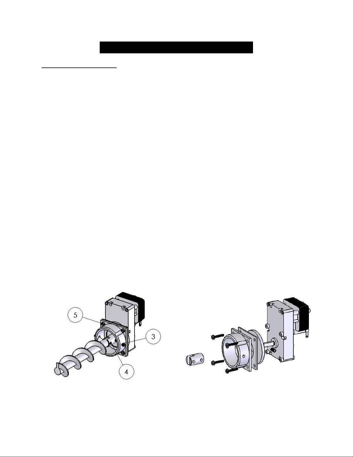
39
IMPORTANT! LISEZ ET SUIVEZ TOUTES LES INSTRUCTIONS POUR L’INSTALLATION ET L’ENTRETIEN,
NOTAMMENT CELLES PORTANT SUR LE NETTOYAGE DU POÊLE À EFFECTUER SELON LES DIRECTIVES ET
CELLES PORTANT SUR LE REMPLACEMENT DES JOINTS (ANNUELLEMENT) ET DES PIÈCES (AU BESOIN).
ENGLAND’S STOVE WORKS N’EST PAS RESPONSABLE DES DOMMAGES NI DES BLESSURES, QUELS QU’ILS SOIENT,
SUBIS EN RAISON DE NÉGLIGENCE OU À CAUSE D’UNE INSTALLATION OU D’UNE UTILISATION DANGEREUSE
DE CE PRODUIT. POUR TOUTE QUESTION, COMMUNIQUEZ AVEC LE SERVICE DE SOUTIEN TECHNIQUE.
REMPLACEMENT DES PIÈCES
Moteur de la vis à granules
1. Avant de procéder au remplacement d’une pièce, assurez-vous que l’appareil est débranché
et complètement refroidi. Assurez-vous également que la trémie est vide avant de tenter
d’enlever ou de remplacer l’ensemble moteur de la vis à granules.
2. Retirez les panneaux latéraux et le panneau arrière comme indiqué précédemment à la
page 35 de ce guide et dans la section « Nettoyage du ventilateur d’évacuation ».
Avant de desserrer des boulons, détachez le faisceau de câbles du moteur.
3. Repérez l’ensemble du moteur de la vis à granules à l’arrière du poêle et commencez
par desserrer les deux vis de calage hexagonales de chaque côté du raccord en fonte du
moteur.
4. Faites glisser l’ensemble vis à granules hors du tube jusqu’à ce que la vis de calage
hexagonale, qui retient la vis à granules sur son raccord en acier, soit accessible. Desserrez
cette vis de calage jusqu’à ce que la vis à granules se dégage de l’ensemble vis à granules.
5. Retirez ensuite les quatre vis qui maintiennent en place le raccord en fonte du moteur
de la vis à granules, à l’aide d’une clé de 5/16 po. Faites glisser le raccord en fonte du
moteur de la vis à granules et la plaque d’espacement en acier hors du moteur de la vis.
6. Dévissez la vis de calage hexagonale qui fixe le raccord en acier à l’arbre de sortie du
moteur de la vis à granules, puis retirez ce raccord, ainsi que l’amortisseur de vibration
en caoutchouc.
7. Réinstallez les pièces dans l’ordre inverse sur le nouveau moteur de vis à granules,
en faisant attention de ne pas trop serrer les boulons qui maintiennent en place le raccord
en fonte au moteur.
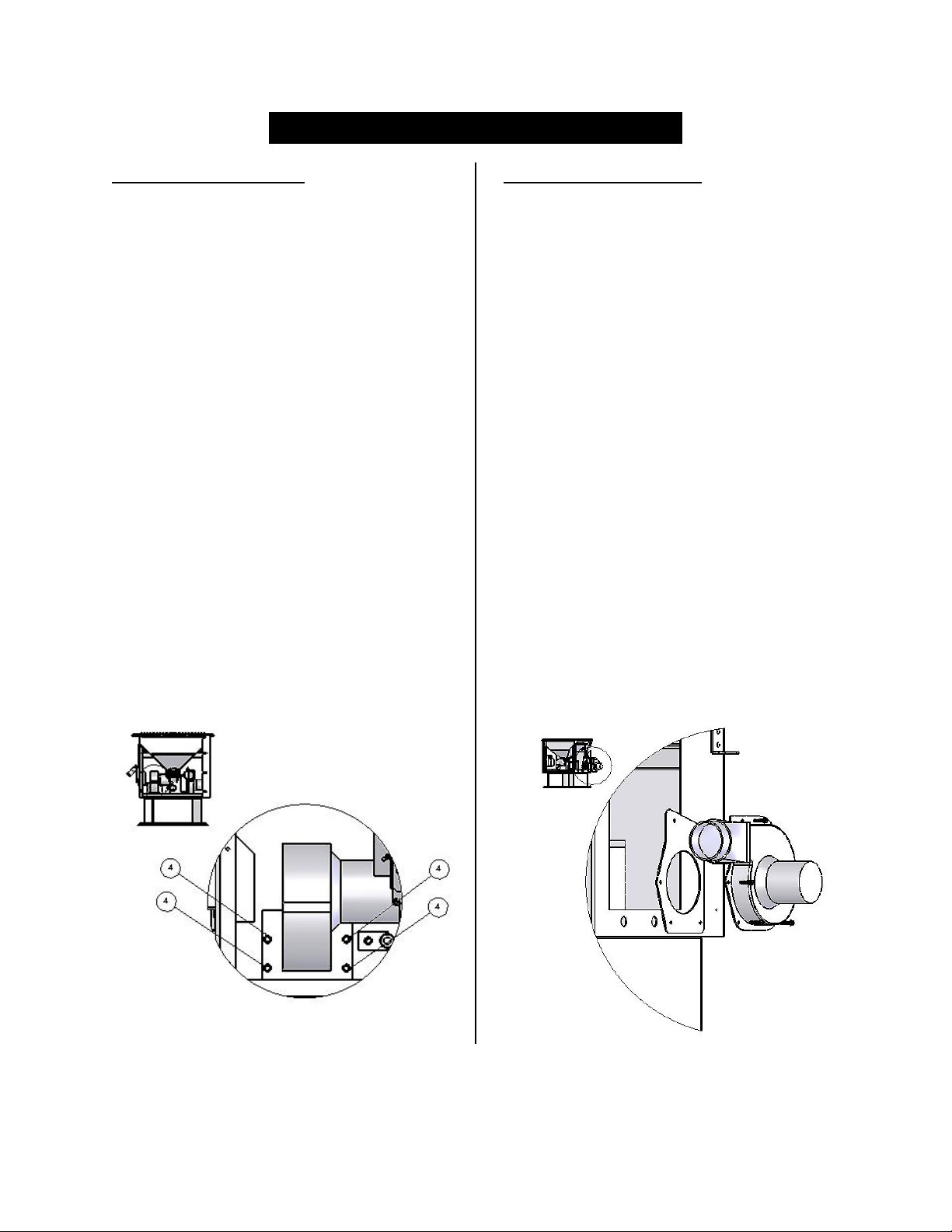
40
IMPORTANT! LISEZ ET SUIVEZ TOUTES LES INSTRUCTIONS POUR L’INSTALLATION ET L’ENTRETIEN,
NOTAMMENT CELLES PORTANT SUR LE NETTOYAGE DU POÊLE À EFFECTUER SELON LES DIRECTIVES ET
CELLES PORTANT SUR LE REMPLACEMENT DES JOINTS (ANNUELLEMENT) ET DES PIÈCES (AU BESOIN).
ENGLAND’S STOVE WORKS N’EST PAS RESPONSABLE DES DOMMAGES NI DES BLESSURES, QUELS QU’ILS SOIENT,
SUBIS EN RAISON DE NÉGLIGENCE OU À CAUSE D’UNE INSTALLATION OU D’UNE UTILISATION DANGEREUSE
DE CE PRODUIT. POUR TOUTE QUESTION, COMMUNIQUEZ AVEC LE SERVICE DE SOUTIEN TECHNIQUE.
REMPLACEMENT DES PIÈCES
Ventilateur de convection
1. Avant de procéder au remplacement
d’une pièce, assurez-vous que l’appareil
est débranché et complètement refroidi.
2. Retirez le panneau latéral droit comme
indiqué précédemment à la page 33 de
ce guide et dans la section « Nettoyage
du ventilateur d’évacuation ».
3. Déconnectez le ventilateur de
convection du faisceau de câblage avant
de desserrer les quatre vis qui le fixent
sur le carénage de convection du poêle.
4. Après avoir desserré et retiré les quatre
vis qui rattachent le ventilateur sur le
poêle, retirez le ventilateur du poêle.
5. L’installation du nouveau ventilateur
s’effectue en sens inverse du
démontage; n’oubliez pas de rebrancher
le nouveau ventilateur au faisceau de
câblage avant de remettre en place le
panneau latéral.
Ventilateur de combustion
1. Avant de procéder au remplacement
d’une pièce, assurez-vous que l’appareil
est débranché et complètement refroidi.
2. Retirez le panneau de gauche comme
indiqué précédemment à la page 33.
3. Déconnectez le système de ventilation du
ventilateur d’évacuation, puis débranchez
le ventilateur de combustion du faisceau
de câblage du poêle. À l’aide d’une clé
de 5/16 po, desserrez et retirez la vis du
détecteur thermique sur le sommet de la
bouche d’évacuation du ventilateur.
4. Desserrez et retirez les cinq vis qui
fixent le ventilateur d’évacuation au
tube d’évacuation. Une fois que vous
avez retiré les vis, soulevez le
ventilateur et retirez-le du poêle.
5. Réinstallez les pièces exactement dans
l’ordre inverse; assurez-vous cependant
que vous avez vérifié l’état du joint du
ventilateur d’évacuation, et remplacez-le
au besoin.
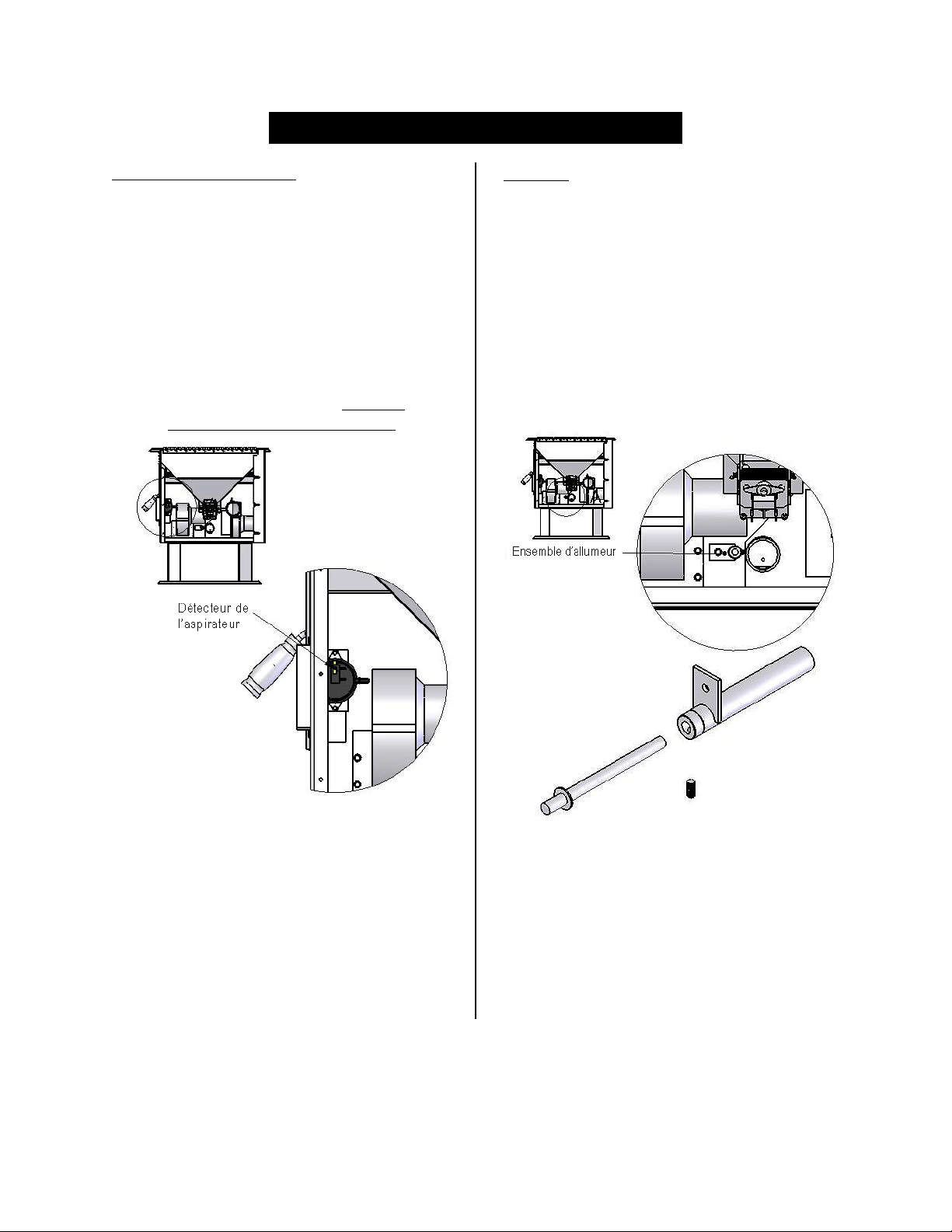
41
IMPORTANT! LISEZ ET SUIVEZ TOUTES LES INSTRUCTIONS POUR L’INSTALLATION ET L’ENTRETIEN,
NOTAMMENT CELLES PORTANT SUR LE NETTOYAGE DU POÊLE À EFFECTUER SELON LES DIRECTIVES ET
CELLES PORTANT SUR LE REMPLACEMENT DES JOINTS (ANNUELLEMENT) ET DES PIÈCES (AU BESOIN).
ENGLAND’S STOVE WORKS N’EST PAS RESPONSABLE DES DOMMAGES NI DES BLESSURES, QUELS QU’ILS SOIENT,
SUBIS EN RAISON DE NÉGLIGENCE OU À CAUSE D’UNE INSTALLATION OU D’UNE UTILISATION DANGEREUSE
DE CE PRODUIT. POUR TOUTE QUESTION, COMMUNIQUEZ AVEC LE SERVICE DE SOUTIEN TECHNIQUE.
REMPLACEMENT DES PIÈCES
Interrupteur de l’aspirateur
1. Avant de procéder au remplacement
d’une pièce, assurez-vous que l’appareil
est débranché et complètement refroidi.
2. Retirez le panneau de droite et le
panneau arrière comme indiqué
précédemment.
3. Repérez le détecteur de l’aspirateur
comme le montre le schéma ci-dessous.
4. Débranchez le faisceau de câbles du
poêle et le tuyau de l’aspirateur du
détecteur de l’aspirateur, en notant
l’emplacement des branchements.
5. À l’aide d’une clé de 5/6 po, retirez
les deux vis qui fixent le détecteur
de l’aspirateur sur son support.
6. Réinstallez les pièces dans l’ordre
inverse; vérifiez soigneusement que
les fils et le tuyau de l’aspirateur sont
raccordés de la même façon que
précédemment (et conformément
au schéma de câblage fourni dans
ce guide).
Allumeur
1. Avant de procéder au remplacement
d’une pièce, assurez-vous que l’appareil
est débranché et complètement refroidi.
2. Retirez le panneau de droite et le panneau
arrière comme indiqué précédemment.
3. Repérez l’allumeur, comme le montre
le schéma ci-dessous.
4. Débranchez le câblage de l’allumeur du
panneau de commande et, à l’aide d’une
clé de 5/16 po, retirez les vis de retenue
de l’allumeur.
5. Desserrez la vis de calage à l’aide d’une
clé hexagonale, puis retirez la vieille
cartouche de l’allumeur.
6. Installez le nouvel allumeur dans le tube
de l’allumeur, resserrez la vis de calage
et réinstallez l’ensemble dans le poêle.
Assurez-vous d’avoir rebranché les
câbles du nouvel allumeur dans le
panneau de commande avant de
procéder au réassemblage.

42
IMPORTANT! LISEZ ET SUIVEZ TOUTES LES INSTRUCTIONS POUR L’INSTALLATION ET L’ENTRETIEN,
NOTAMMENT CELLES PORTANT SUR LE NETTOYAGE DU POÊLE À EFFECTUER SELON LES DIRECTIVES ET
CELLES PORTANT SUR LE REMPLACEMENT DES JOINTS (ANNUELLEMENT) ET DES PIÈCES (AU BESOIN).
ENGLAND’S STOVE WORKS N’EST PAS RESPONSABLE DES DOMMAGES NI DES BLESSURES, QUELS QU’ILS SOIENT,
SUBIS EN RAISON DE NÉGLIGENCE OU À CAUSE D’UNE INSTALLATION OU D’UNE UTILISATION DANGEREUSE
DE CE PRODUIT. POUR TOUTE QUESTION, COMMUNIQUEZ AVEC LE SERVICE DE SOUTIEN TECHNIQUE.
REMPLACEMENT DES PIÈCES
Joints d’étanchéité
1. Porte
o Cet appareil est livré avec un joint d’étanchéité de 12,7 mm autour de la porte, qui
doit être remplacé annuellement. Pour remplacer le joint d’étanchéité de la porte
(n° de pièce AC-DGKEP), retirez d’abord le vieux joint en entier. Avant d’ajouter
le nouvel adhésif, vous devrez peut-être gratter la vieille colle du montant de porte.
Après avoir ajouté de la colle et installé le joint, fermez et verrouillez la porte,
et laissez-la ainsi pendant vingt-quatre heures pour que la colle durcisse.
2. Fenêtre
o Si vous remplacez le joint de la fenêtre (pièce nº PU-GGK), un des côtés du nouveau
joint sera déjà enduit de colle. Retirez le papier du côté adhésif et placez le joint
autour du bord extérieur de la vitre, centré sur le rebord. Repliez les bords du joint
sur la vitre en formant un « U ».
3. Ventilateur de combustion
o Inspectez le joint du ventilateur de combustion (pièce nº PU-CBMG) chaque fois
que vous retirez ou nettoyez le ventilateur de combustion et remplacez-le au besoin.
4. De plus le joint du couvercle de la trémie doit être inspecté et remplacé tous les ans ou
plus fréquemment si nécessaire (voir « Vérification des joints » dans la section
« Entretien annuel »).
Fini
Ce nouvel appareil a été peint avec de la peinture qui résiste aux températures élevées et
devrait conserver son aspect d’origine pendant des années. Si l’appareil est mouillé et que des taches
de rouille apparaissent, vous pouvez les poncer avec de la laine d’acier fine et repeindre l’appareil.
Il est important de n’utiliser que de la peinture en aérosol haute température (pièce # AC-MBSP),
car les autres types de peinture pourraient ne pas adhérer à la surface ou ne pas supporter les
températures élevées. De même, certaines marques de peinture n’adhèrent pas à certaines autres
marques de peinture; par conséquent, nous vous recommandons fortement d’utiliser notre peinture
en aérosol résistant aux températures élevées exclusive.
Vitre
Cet appareil est doté d’un ensemble de vitrocéramique en trois parties (n° de pièce
AC-G40 [vitre centrale] et n° de pièce AC-G41 [vitres latérales] dans la porte vitrée. Un joint
de fenêtre autoadhésif est fourni avec les fenêtres de rechange achetées directement à England’s
Stove Works. Les rayures de surface sont acceptables, mais si n’importe quelle partie de cette
vitre se fissure, arrêtez l’appareil et remplacez la fenêtre par une vitre en vitrocéramique achetée
directement à England’s Stove Works. Ne remplacez jamais la vitre en vitrocéramique par une
vitre en verre trempé ou tout autre type de verre.
L’ENTRETIEN INADÉQUAT DES JOINTS, Y COMPRIS LE DÉFAUT
DE REMPLACEMENT DES JOINTS, PEUT SE TRADUIRE PAR DES FUITES
D’AIR CAUSANT DES RETOURS DE FUMÉE.
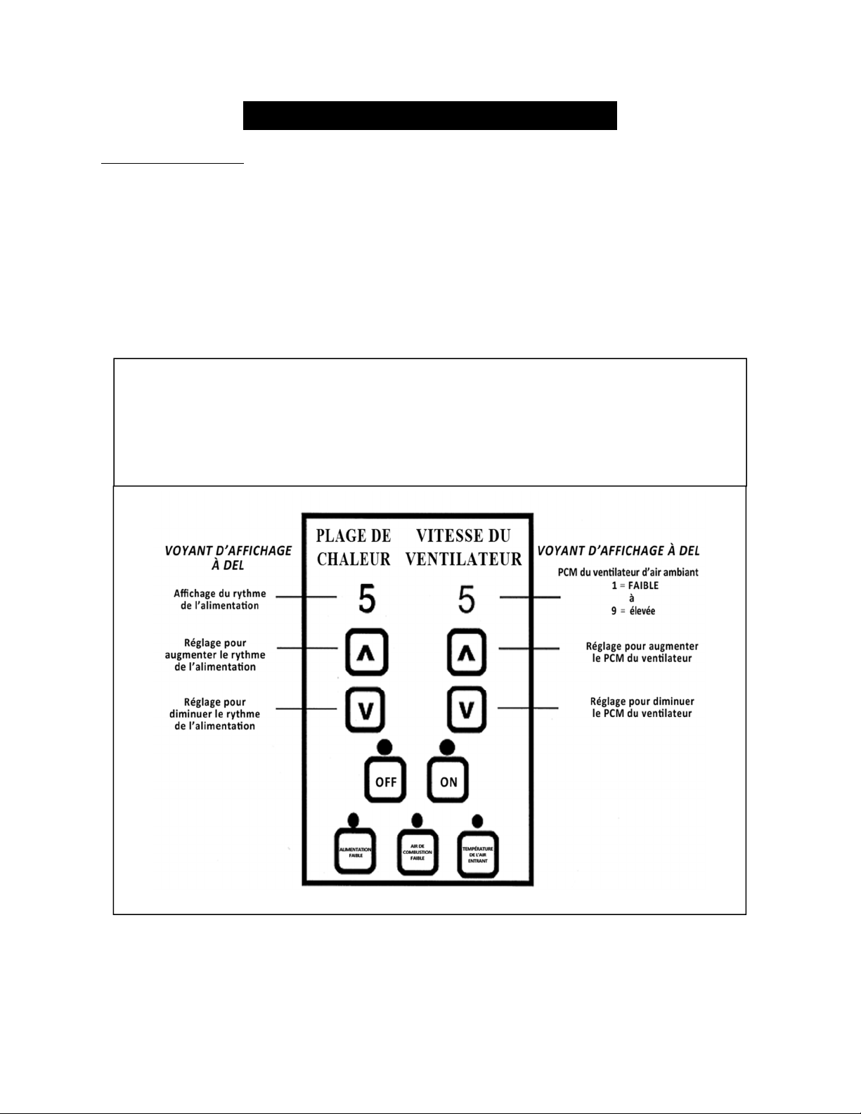
43
IMPORTANT! LISEZ ET SUIVEZ TOUTES LES INSTRUCTIONS POUR L’INSTALLATION ET L’ENTRETIEN,
NOTAMMENT CELLES PORTANT SUR LE NETTOYAGE DU POÊLE À EFFECTUER SELON LES DIRECTIVES ET
CELLES PORTANT SUR LE REMPLACEMENT DES JOINTS (ANNUELLEMENT) ET DES PIÈCES (AU BESOIN).
ENGLAND’S STOVE WORKS N’EST PAS RESPONSABLE DES DOMMAGES NI DES BLESSURES, QUELS QU’ILS SOIENT,
SUBIS EN RAISON DE NÉGLIGENCE OU À CAUSE D’UNE INSTALLATION OU D’UNE UTILISATION DANGEREUSE
DE CE PRODUIT. POUR TOUTE QUESTION, COMMUNIQUEZ AVEC LE SERVICE DE SOUTIEN TECHNIQUE.
REMPLACEMENT DES PIÈCES
Panneau de commande
Le panneau de commande (pièce nº PU-CBEP) est un panneau d’affichage numérique.
Ce panneau comprend plusieurs réglages qui aident à faire fonctionner l’appareil. Avant de retirer le
panneau de commande, enlevez le panneau latéral droit à l’aide d’un tournevis à douille ou d’une clé
de 5/16 po. Pour retirer le panneau de commande de l’appareil, desserrez les deux vis externes et poussez
le panneau vers l’intérieur du poêle. Le panneau de commande utilise un fusible à action rapide de 6 A.
REMARQUE : Les trois boutons de commande inférieurs sont préréglés en usine et ne doivent pas être
réglés par les utilisateurs. Consultez la section « Utilisation quotidienne » à la page 17 du
présent guide pour plus d’instructions sur les réglages du panneau de commande.
Plages de chaleur recommandées :
Combustion faible : Réglage de plage de chaleur : 1 Réglage du ventilateur d’air ambiant : 1
Moyennement faible : Réglage de plage de chaleur : 2 – 3 Réglage du ventilateur d’air ambiant : *
Moyennement élevée : Réglage de plage de chaleur : 4 – 8 Réglage du ventilateur d’air ambiant : *
Combustion maximale : Réglage de plage de chaleur : 9 Réglage du ventilateur d’air ambiant : 9
* REMARQUE : La vitesse du ventilateur s’ajustera automatiquement en fonction de la plage de
chaleur
q
ue vous sélectionnez.b
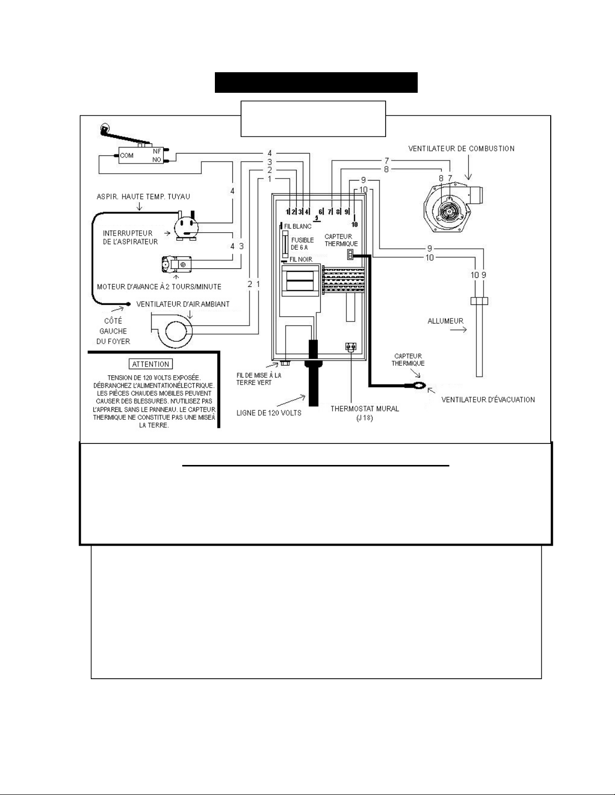
44
IMPORTANT! LISEZ ET SUIVEZ TOUTES LES INSTRUCTIONS POUR L’INSTALLATION ET L’ENTRETIEN,
NOTAMMENT CELLES PORTANT SUR LE NETTOYAGE DU POÊLE À EFFECTUER SELON LES DIRECTIVES ET
CELLES PORTANT SUR LE REMPLACEMENT DES JOINTS (ANNUELLEMENT) ET DES PIÈCES (AU BESOIN).
ENGLAND’S STOVE WORKS N’EST PAS RESPONSABLE DES DOMMAGES NI DES BLESSURES, QUELS QU’ILS SOIENT,
SUBIS EN RAISON DE NÉGLIGENCE OU À CAUSE D’UNE INSTALLATION OU D’UNE UTILISATION DANGEREUSE
DE CE PRODUIT. POUR TOUTE QUESTION, COMMUNIQUEZ AVEC LE SERVICE DE SOUTIEN TECHNIQUE.
SCHÉMA DE CÂBLAGE
Attention – risque de choc électrique
Appuyez sur le bouton « OFF » (arrêt) et laissez l’appareil se refroidir
complètement AVANT de le débrancher et de procéder à son entretien
ou au remplacement d’une pièce.
Ris
q
ue de choc électri
q
ue si l’a
pp
areil n’est
p
as débranché avant son entretien.
Schéma du panneau de
commande (câblage)
Interrupteurdesécuritéducouvercledelatrémie:cetappareilestégalementdotéd’un
interrupteurdesécuritéducouvercledelatrémie(piècenºAC‐HLSB)quiestdirectement
raccordéaumoteurdelavisàgranules.Dansl’éventualitéoùlecouvercledelatrémieestlaissé
ouvertpendantque
lepoêleestenmarche,l’interrupteurducouvercledelatrémieempêchera
lavisàgranulesdetourner.Celapermetd’éviterquelessous‐produitsdecombustionpénètrent
danslamaisonàl’aidedel’ouverturelaisséeparlecouvercledelatrémieet aussid’empêcher
l’appareildefonctionnerpendantque
lecouvercleestouvert.Uneutilisationinadéquatede
l’interrupteurdesécuritéducouvercledelatrémieempêcheralavisàgranulesdetourner;
parconséquent,lepoêlenefonctionnerapas.NeplacezJAMAISvotremainnitoutautreobjet,
prèsdelavisàgranulespendantquelepoêleestbranché.
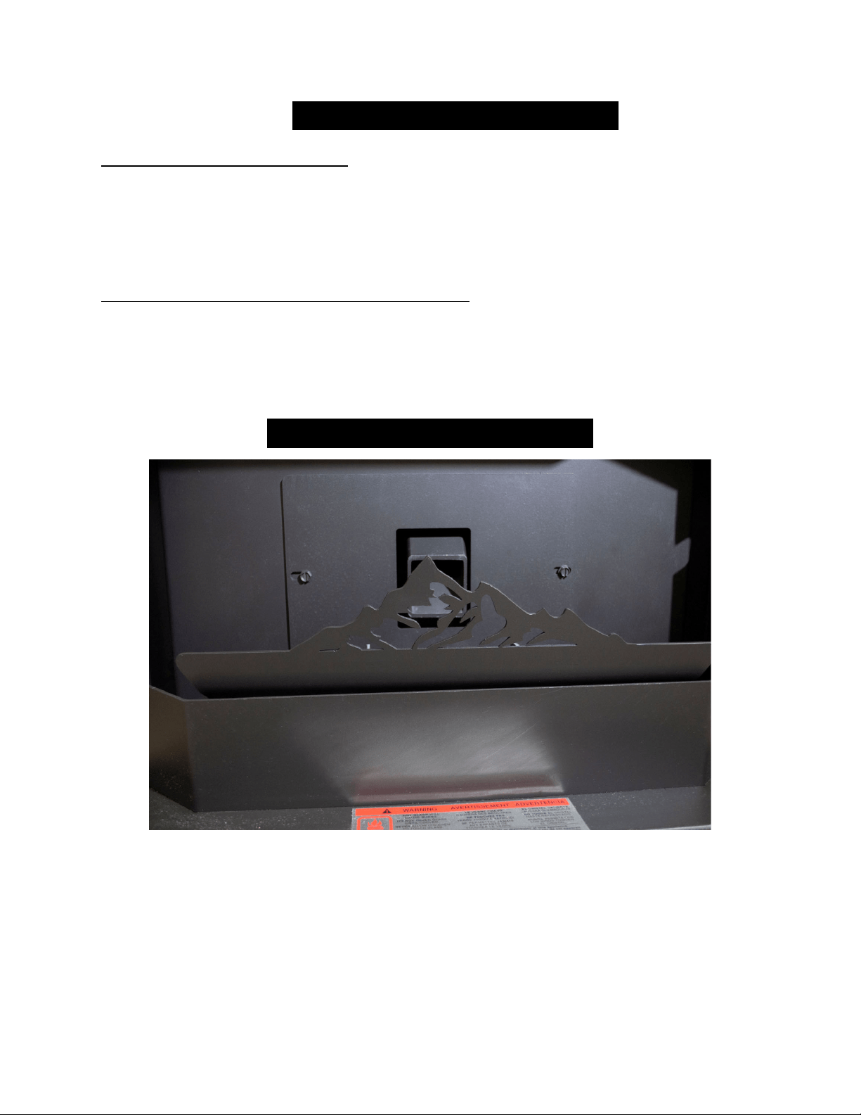
45
IMPORTANT! LISEZ ET SUIVEZ TOUTES LES INSTRUCTIONS POUR L’INSTALLATION ET L’ENTRETIEN,
NOTAMMENT CELLES PORTANT SUR LE NETTOYAGE DU POÊLE À EFFECTUER SELON LES DIRECTIVES ET
CELLES PORTANT SUR LE REMPLACEMENT DES JOINTS (ANNUELLEMENT) ET DES PIÈCES (AU BESOIN).
ENGLAND’S STOVE WORKS N’EST PAS RESPONSABLE DES DOMMAGES NI DES BLESSURES, QUELS QU’ILS SOIENT,
SUBIS EN RAISON DE NÉGLIGENCE OU À CAUSE D’UNE INSTALLATION OU D’UNE UTILISATION DANGEREUSE
DE CE PRODUIT. POUR TOUTE QUESTION, COMMUNIQUEZ AVEC LE SERVICE DE SOUTIEN TECHNIQUE.
ACCESSOIRES EN OPTION
Thermostat mural (PU-DTSTAT)
L’installation de ce thermostat mural permet de faire fonctionner le 25-CBEP
comme s’il s’agissait d’une chaudière : le poêle s’arrêtera et se rallumera en fonction
des variations de température (en mode « On/Off » [marche/arrêt], consultez la section
« Utilisation du thermostat » page 23). Cela permettra de garder la température stable
dans la maison tout en économisant les granules.
Thermostat avec commande à distance (AC-3003)
Le thermostat avec commande à distance pour le 25-CBEP vous offre un degré de
convivialité plus poussé en vous permettant de régler la température à partir de n’importe
quel endroit dans la maison. La commande à distance permet de régler précisément la
température à partir de l’endroit où vous vous trouvez et ne nécessite que six (6) piles de
type AA pour fonctionner.
ACCESSOIRES STANDARD
Votre poêle est équipé d’une évacuation d’air décorative en acier. Bien que ce dispositif
soit conçu pour renforcer l’aspect esthétique du feu, il n’en est pas moins pratique pour
assurer la propreté de la vitre. L’évacuation d’air doit s’incliner vers l’avant (en direction
de la vitre) pendant le fonctionnement du poêle. N’oubliez pas de visiter régulièrement
le site heatredefined.com pour découvrir les futurs modèles d’évacuation d’air qui
donneront un nouvel aspect à votre poêle.
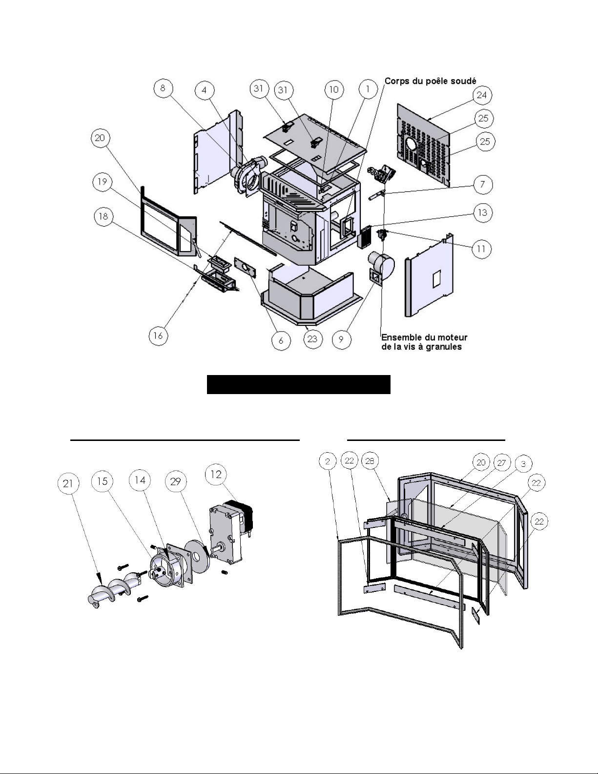
46
IMPORTANT! LISEZ ET SUIVEZ TOUTES LES INSTRUCTIONS POUR L’INSTALLATION ET L’ENTRETIEN,
NOTAMMENT CELLES PORTANT SUR LE NETTOYAGE DU POÊLE À EFFECTUER SELON LES DIRECTIVES ET
CELLES PORTANT SUR LE REMPLACEMENT DES JOINTS (ANNUELLEMENT) ET DES PIÈCES (AU BESOIN).
ENGLAND’S STOVE WORKS N’EST PAS RESPONSABLE DES DOMMAGES NI DES BLESSURES, QUELS QU’ILS SOIENT,
SUBIS EN RAISON DE NÉGLIGENCE OU À CAUSE D’UNE INSTALLATION OU D’UNE UTILISATION DANGEREUSE
DE CE PRODUIT. POUR TOUTE QUESTION, COMMUNIQUEZ AVEC LE SERVICE DE SOUTIEN TECHNIQUE.
SCHÉMA DES PIÈCES
Ensemble moteur de vis à granules Ensemble porte en acier

47
IMPORTANT! LISEZ ET SUIVEZ TOUTES LES INSTRUCTIONS POUR L’INSTALLATION ET L’ENTRETIEN,
NOTAMMENT CELLES PORTANT SUR LE NETTOYAGE DU POÊLE À EFFECTUER SELON LES DIRECTIVES ET
CELLES PORTANT SUR LE REMPLACEMENT DES JOINTS (ANNUELLEMENT) ET DES PIÈCES (AU BESOIN).
ENGLAND’S STOVE WORKS N’EST PAS RESPONSABLE DES DOMMAGES NI DES BLESSURES, QUELS QU’ILS SOIENT,
SUBIS EN RAISON DE NÉGLIGENCE OU À CAUSE D’UNE INSTALLATION OU D’UNE UTILISATION DANGEREUSE
DE CE PRODUIT. POUR TOUTE QUESTION, COMMUNIQUEZ AVEC LE SERVICE DE SOUTIEN TECHNIQUE.
Numérodepièce PièceDescription N°defigure
Jointsd’étanchéité
PU‐HLG Jointducouvercledelatrémie 1
AC‐DGKEP Jointdelaporte 2
AC‐GGKEP Kitdejointdevitretroispièces 3
PU‐CBMG Jointdumoteuretduventilateurd’évacuation 4
PU‐CGEP Jointdusupport 6
Composantsélectriques
PU‐CHA Cartouche(allumeur) 7
PU‐076002B Ventilateurd’évacuation 8
PU‐4C442 Ventilateurd’airambiant 9
AC‐HLSB Interrupteurducouvercledelatrémie 10
CU‐VS Interrupteurdel’aspirateur1,27mm(0,05po)CE 11
CU‐047042 Moteurdelavisàgranulesà2toursparminute 12
PU‐CBEP Panneaudecommande 13
Fonte
CA‐AMPP
Colletdemontageenfontedumoteurdelavisà
granules
14
Acier
CA‐AC Raccordenacierdelavisàgranules 15
IP‐25EP Couvercledelasortied’air 16
PU‐BPCEP Support 18
PU‐BPEP Potdecombustion 19
CA‐40 Porteenacier 20
Évacuationd’airdécorativeenacier Nonillustré
PU‐AFEP Visàgranulesenacier 21
AC‐GSEP Supportsdevitre 22
PU‐BREP Socleetcolonne23
PU‐RAPEP Panneaud’accèsarrière 24
PU‐EPRCP Couverclesdesorificesd’admissionetd’évacuation 25
Vitre
AC‐G40 Vitragetroispièces‐Centre 27
AC‐G41 Vitragetroispièces‐Côté 28
Divers
CU‐RG Bagueencaoutchoucdumoteurdelavisàgranules 29
PU‐VH Tuyaudel’aspirateurhautetempérature Nonillustré
PU‐62‐40‐151‐3 Loquetducouvercledelatrémie 31
AC‐SHN Poignéeàressortennickel Nonillustré
AC‐SH Poignéeàressortenlaiton Nonillustré
PU‐EDIC Revêtementisolantdutubed’évacuation Nonillustré
LISTE DES PIÈCES DE RECHANGE
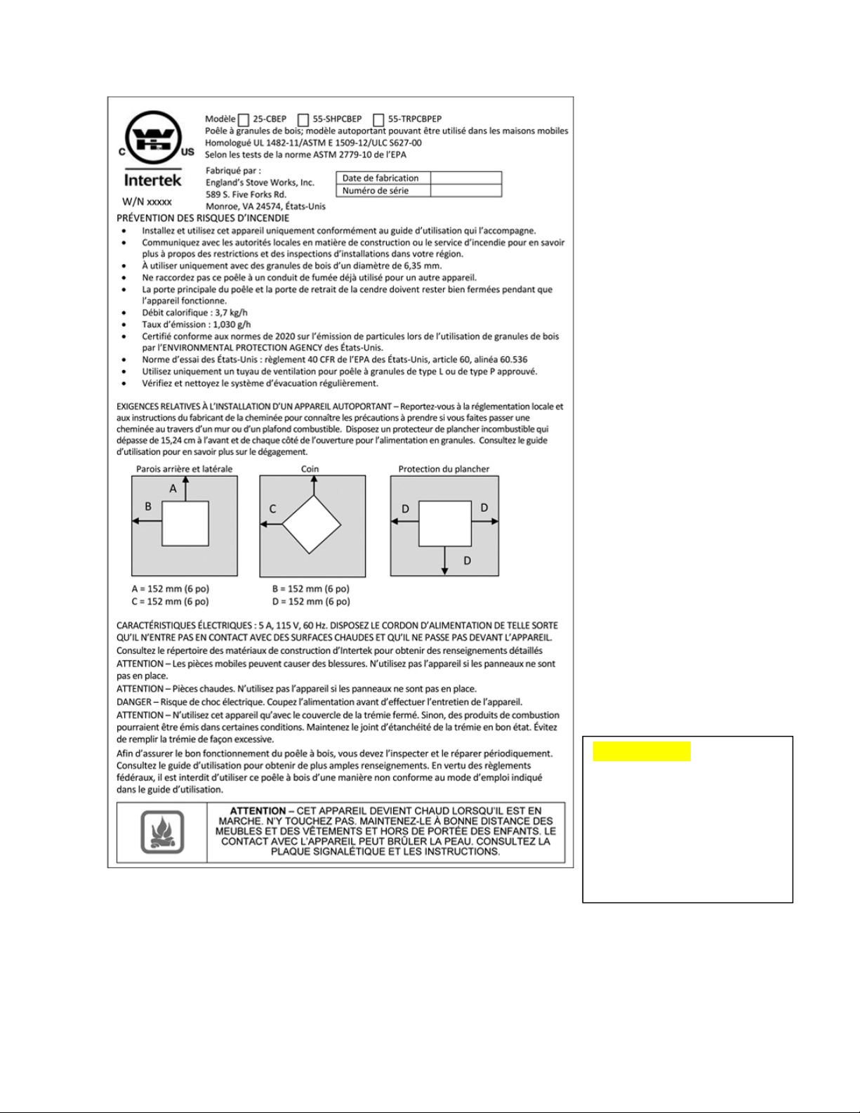
48
IMPORTANT! LISEZ ET SUIVEZ TOUTES LES INSTRUCTIONS POUR L’INSTALLATION ET L’ENTRETIEN,
NOTAMMENT CELLES PORTANT SUR LE NETTOYAGE DU POÊLE À EFFECTUER SELON LES DIRECTIVES ET
CELLES PORTANT SUR LE REMPLACEMENT DES JOINTS (ANNUELLEMENT) ET DES PIÈCES (AU BESOIN).
ENGLAND’S STOVE WORKS N’EST PAS RESPONSABLE DES DOMMAGES NI DES BLESSURES, QUELS QU’ILS SOIENT,
SUBIS EN RAISON DE NÉGLIGENCE OU À CAUSE D’UNE INSTALLATION OU D’UNE UTILISATION DANGEREUSE
DE CE PRODUIT. POUR TOUTE QUESTION, COMMUNIQUEZ AVEC LE SERVICE DE SOUTIEN TECHNIQUE.
Cette étiquette comprend
des renseignements de
sécurité, tels que la norme
d’essai UL/ULC et d’autres
informations à l’intention
de vos représentants locaux
ou de toute autre personne
qui peut en avoir besoin.

49
IMPORTANT! LISEZ ET SUIVEZ TOUTES LES INSTRUCTIONS POUR L’INSTALLATION ET L’ENTRETIEN,
NOTAMMENT CELLES PORTANT SUR LE NETTOYAGE DU POÊLE À EFFECTUER SELON LES DIRECTIVES ET
CELLES PORTANT SUR LE REMPLACEMENT DES JOINTS (ANNUELLEMENT) ET DES PIÈCES (AU BESOIN).
ENGLAND’S STOVE WORKS N’EST PAS RESPONSABLE DES DOMMAGES NI DES BLESSURES, QUELS QU’ILS SOIENT,
SUBIS EN RAISON DE NÉGLIGENCE OU À CAUSE D’UNE INSTALLATION OU D’UNE UTILISATION DANGEREUSE
DE CE PRODUIT. POUR TOUTE QUESTION, COMMUNIQUEZ AVEC LE SERVICE DE SOUTIEN TECHNIQUE.
GARANTIE LIMITÉE DE CINQ (5) ANS
À partir de la date d’achat par le propriétaire d’origine
Modèles 25-CBEP / 55-SHPCBEP / 55-TRPCBEP
La garantie limitée du fabricant couvre les éléments ci-dessous :
Cinq ans :
1. Les joints d’acier au carbone et les joints soudés du foyer sont garantis pendant
cinq (5) ans contre le fendillement.
2. La porte et les charnières en acier sont garanties pendant cinq (5) ans contre la
fissuration.
Un an :
1. Les pièces telles que la trémie, la vis à granules, le pot de combustion, le
déflecteur, l’axe de la vis à granules et les fixations sont garanties pendant
un (1) an contre les fissures, les brisures et le fendillement des joints soudés.
2. Les composants électriques, les accessoires, le verre et la surface peinte du
poêle sont garantis pendant un (1) an à partir de la date d’achat.
Conditions et exclusions
1. Les dommages découlant d’un emballement annulent votre garantie.
2. Cette garantie ne s’applique pas si les dommages découlent d’un accident,
d’une manipulation inadéquate, d’une installation inadéquate, d’une utilisation
inadéquate ou abusive, d’une réparation non autorisée ou d’une tentative de
réparation non autorisée.
3. Le fabricant n’est pas responsable des dommages indirects, accessoires ou
consécutifs découlant du produit, y compris les coûts ou dépenses, la fourniture
de matériel de rechange ou la réparation pendant les périodes de mauvais
fonctionnement ou de non-utilisation du produit*.
4. Le fabricant déclinera toute responsabilité pour les dommages consécutifs
en cas de violation de toute garantie écrite ou implicite.
5. Ce produit est homologué par l’EPA pour son utilisation de granules de bois
de qualité supérieure. La garantie ne s’applique pas si le produit est utilisé pour
brûler des matériaux non conformes à son homologation par l’EPA. La garantie ne
s’applique pas si le produit n’est pas utilisé conformément au guide d’utilisation.
Certains États ou certaines provinces ne permettent pas l’exclusion ou la limitation des dommages accessoires ou consécutifs,
de sorte que les exclusions mentionnées ci-dessus peuvent ne pas s’appliquer à vous.

50
IMPORTANT! LISEZ ET SUIVEZ TOUTES LES INSTRUCTIONS POUR L’INSTALLATION ET L’ENTRETIEN,
NOTAMMENT CELLES PORTANT SUR LE NETTOYAGE DU POÊLE À EFFECTUER SELON LES DIRECTIVES ET
CELLES PORTANT SUR LE REMPLACEMENT DES JOINTS (ANNUELLEMENT) ET DES PIÈCES (AU BESOIN).
ENGLAND’S STOVE WORKS N’EST PAS RESPONSABLE DES DOMMAGES NI DES BLESSURES, QUELS QU’ILS SOIENT,
SUBIS EN RAISON DE NÉGLIGENCE OU À CAUSE D’UNE INSTALLATION OU D’UNE UTILISATION DANGEREUSE
DE CE PRODUIT. POUR TOUTE QUESTION, COMMUNIQUEZ AVEC LE SERVICE DE SOUTIEN TECHNIQUE.
Procédure
L’acheteur doit soumettre une réclamation de défaut pendant la période de garantie
et payer le transport vers un centre de service et à partir d’un centre de service désigné
par le fabricant. Le détaillant qui a vendu l’appareil ou le fabricant, à notre gré,
effectuera la réparation sous garantie.
Autres droits
Cette garantie vous confère des droits précis. Il est possible que vous disposiez
également d’autres droits, qui varient d’un État ou d’une province à l’autre.
England’s Stove Works, Inc.
P.O. Box 206
Monroe, VA 24574, États-Unis
(800) 245-6489
Pour effectuer une réclamation au titre de la garantie, veuillez communiquer avec
notre service de soutien technique au 1 800 245-6489. Vous pouvez également
effectuer une réclamation au titre de la garantie sur le site www.heatredefined.com
Dans le cas des pièces, les procédures de remplacement au titre de la garantie se trouvent
sur le site de notre magasin de pièces : store.heatredefined.com
Veuillez noter : Cette garantie est nulle et non avenue si l’acheteur n’envoie pas la
carte d’enregistrement de la garantie ci-jointe ET une copie du reçu de vente dans les
trente (30) jours, à compter de la date d’achat.
Cette garantie est non transférable.

51
IMPORTANT! LISEZ ET SUIVEZ TOUTES LES INSTRUCTIONS POUR L’INSTALLATION ET L’ENTRETIEN,
NOTAMMENT CELLES PORTANT SUR LE NETTOYAGE DU POÊLE À EFFECTUER SELON LES DIRECTIVES ET
CELLES PORTANT SUR LE REMPLACEMENT DES JOINTS (ANNUELLEMENT) ET DES PIÈCES (AU BESOIN).
ENGLAND’S STOVE WORKS N’EST PAS RESPONSABLE DES DOMMAGES NI DES BLESSURES, QUELS QU’ILS SOIENT,
SUBIS EN RAISON DE NÉGLIGENCE OU À CAUSE D’UNE INSTALLATION OU D’UNE UTILISATION DANGEREUSE
DE CE PRODUIT. POUR TOUTE QUESTION, COMMUNIQUEZ AVEC LE SERVICE DE SOUTIEN TECHNIQUE.
ENREGISTREMENT DE LA GARANTIE
sur les produits england’s stove works
®
Renseignements sur l’acheteur*
I. Nom de l’acheteur ______________________________________________________
II. Adresse ______________________________________________________________
III. Ville ____________________Province ________Code postal___________________
IV. Numéro de téléphone ___________________________________________________
V. Courriel ______________________________________________________________
Renseignements sur le détaillant*
VI. Nom du détaillant _____________________________________________________
VII. Adresse _____________________________________________________________
VIII. Ville ___________________ Province ________ Code postal _________________
Renseignements sur l’appareil*
IX. Numéro de modèle ___________________ Date d’achat ______________________
X. Prix d’achat _________________________
XI. Numéro de série _____________________ Date de fabrication _________________
Questions relatives à l’achat
Comment avez-vous entendu parler de notre produit? (Veuillez cocher l’une des réponses
suivantes.)
De bouche à oreille ____________ Démonstration _______________ Internet ________
Autre : _________________________________________________________________
À quel endroit vous a-t-on donné des renseignements sur notre produit?
Au téléphone _______ Chez un détaillant (nom du détaillant) ___________ Internet ____
Autre : _________________________________________________________________
* Renseignements nécessaires

52
IMPORTANT! LISEZ ET SUIVEZ TOUTES LES INSTRUCTIONS POUR L’INSTALLATION ET L’ENTRETIEN,
NOTAMMENT CELLES PORTANT SUR LE NETTOYAGE DU POÊLE À EFFECTUER SELON LES DIRECTIVES ET
CELLES PORTANT SUR LE REMPLACEMENT DES JOINTS (ANNUELLEMENT) ET DES PIÈCES (AU BESOIN).
ENGLAND’S STOVE WORKS N’EST PAS RESPONSABLE DES DOMMAGES NI DES BLESSURES, QUELS QU’ILS SOIENT,
SUBIS EN RAISON DE NÉGLIGENCE OU À CAUSE D’UNE INSTALLATION OU D’UNE UTILISATION DANGEREUSE
DE CE PRODUIT. POUR TOUTE QUESTION, COMMUNIQUEZ AVEC LE SERVICE DE SOUTIEN TECHNIQUE.
Avisimportant
L’informationd’enregistrementDOITêtreverséedansnosdossierspo urquela
présentegarantiesoitvalide.Veuilleznousenvoyercetteinformationdansles
trente(30)jourssuivantladated’achatinitiale.
Ilyatroismoyensfacilesdenousfaireparvenircetteinformation.
Adressepostale
England’sStoveWorks,Inc.
TechnicalsupportDepartment
P.O.Box206
Monroe,Virginia24574,États‐Unis
Partélécopieuraunumérosuivant:
1434929‐4810–24heuresparjour
Enregistrementenligne:
Pourvousinscrireenligne,visiteznotresiteWebpourl’enregistrement
delagarantieàl’adresse
http://www.heatredefined.com
Veuillez noter : Cette garantie sera nulle et non avenue si l’acheteur n’envoie pas la carte
d’enregistrement de la garantie ci-jointe ET une copie du reçu dans les trente (30) jours, à
compter de la date d’achat.
Cette garantie est non transférable.

53
IMPORTANT! LISEZ ET SUIVEZ TOUTES LES INSTRUCTIONS POUR L’INSTALLATION ET L’ENTRETIEN,
NOTAMMENT CELLES PORTANT SUR LE NETTOYAGE DU POÊLE À EFFECTUER SELON LES DIRECTIVES ET
CELLES PORTANT SUR LE REMPLACEMENT DES JOINTS (ANNUELLEMENT) ET DES PIÈCES (AU BESOIN).
ENGLAND’S STOVE WORKS N’EST PAS RESPONSABLE DES DOMMAGES NI DES BLESSURES, QUELS QU’ILS SOIENT,
SUBIS EN RAISON DE NÉGLIGENCE OU À CAUSE D’UNE INSTALLATION OU D’UNE UTILISATION DANGEREUSE
DE CE PRODUIT. POUR TOUTE QUESTION, COMMUNIQUEZ AVEC LE SERVICE DE SOUTIEN TECHNIQUE.
REMARQUE:
RENSEIGNEMENTSSURL’EPA
Lesajoutssuivantsàvotreguided’utilisationvouspermettrontderéduireau
minimumlesémissionsproduitesparvotrepoêleàbois.Desconseilsdesécurité
importantsvousso ntégalementprésentés.
‐ Installationadéquate–Veuillezconsulterlasectionsurl’installationdevotreguide
d’utilisationetsuivrelesdirectivesénoncéesafind’assurerlasécuritéetderéduire
auminimumlesémissions.
Renseignementssupplémentaires:
Ventilation:
Assurez‐vousderespecterlesrecommandationsindiquéesdansvotreguided’utilisation
concernantlaventilation,notammentcellessurlesystèmedeconduitdefuméeetletuyau
deventilation.
Veuillezégalementnoterqueleraccordd’airextérieur(airdecombustion)estOBLIGATOIRE
pourfairefonctionnerlepoêledemanièreappropri éeet sécuritaire
etpourréduireau
mínimumlesémissions.
Commeindiquédansleguided’utilisation,lesterminaisonsdeséventsdoiventêtredégagées;
communiquezavecleservicedesoutientechniquesivousavezdesquestions.Composez
Assurez‐vousdebiensuivretouteslesinstructionsdufabricantrelativesausystème
deventilation,surtoutparrapportauxdistancesminimalesnécessairesaveclesmatières
combustibles.
Cepoêleàgranulesfonctionneavecàunsystèmeàtiragenégatifquitirel’airde
combustionautraversdupotdecombustionetpoussel’airviciéautraversdutuyaude
ventilationpuisàl’extérieurdubâtiment.Cetappareildoitêtreinstalléconformémentaux
techniquesdeventilationdécritesendétaildansleguided’utilisation.Lenon‐respectdeces
techniquespourraitréduirelerendementdupoêleetcauserdesdommagesmatériels,des
blessuresoulamort.England’sStoveWorksn’estpasresponsabledesdommagescausés
paruneinstallationincorrecteounonsécuritaire.
POÊLE À GRANULES – Conseils supplémentaires relatifs
à la sécurité et aux émissions.

54
IMPORTANT! LISEZ ET SUIVEZ TOUTES LES INSTRUCTIONS POUR L’INSTALLATION ET L’ENTRETIEN,
NOTAMMENT CELLES PORTANT SUR LE NETTOYAGE DU POÊLE À EFFECTUER SELON LES DIRECTIVES ET
CELLES PORTANT SUR LE REMPLACEMENT DES JOINTS (ANNUELLEMENT) ET DES PIÈCES (AU BESOIN).
ENGLAND’S STOVE WORKS N’EST PAS RESPONSABLE DES DOMMAGES NI DES BLESSURES, QUELS QU’ILS SOIENT,
SUBIS EN RAISON DE NÉGLIGENCE OU À CAUSE D’UNE INSTALLATION OU D’UNE UTILISATION DANGEREUSE
DE CE PRODUIT. POUR TOUTE QUESTION, COMMUNIQUEZ AVEC LE SERVICE DE SOUTIEN TECHNIQUE.
Renseignementssupplémentairessurlaventilation
Nemélangezpasetn’associezpasdepiècesprovenantdedifférentsfabricantslorsquevous
installezlesystèmedeventilation(parexemple,n’util isezPASletuyaud’unfabricantavecla
gainepourtuyaud’unautrefabricant).
Ilestnécessairequeletuyausoitdisposéverticalementsuraumoins91,44cm
pourcréer
untiragenatureldanslesystème.Cecifaciliteral’évacuationdelafuméedupoêledanslecas
d’unecoupured’électricitéoud’unepanneduventilateurdecombustion.
Lessystèmesdeventilationlongsde4,57moumoinsdevraientêtrecomposésintégralement
detuyauxpourpoêleàgranules
de3poafinderéduirelespertesattribua blesàlafriction.
Lessystèmespluslongs,quantàeux,doiventêtrecomposésdetuyauxpourpoêleàgranules
de4po.
Nefaitespasaboutirlesystèmedeventilationdirectementsousunestructurecombustible
commeunporcheouuneterrasse.
RespectezlesnormesNFPA211énuméréesci‐dessous,relativesàl’emplacementdela
terminaisondessystèmesdeventilationenfonctiondel’emplacementdesfenêtresetdes
autresouverturesd’unerésidence.
o NFPA211(version2006)Section10.4Terminaison:10.4.5
(1)L’extrémitédesortiedessystèmesmécaniquesdetirage
autresquelesdispositifsde
ventilationdirecte(dispositifspourdesappareilsàcombustionétanche)doitêtresituée
conformémentauxindicationssuivantes:
(a)Àaumoins0,91m(3pi)au‐dessusdetouteprised’airparventilation
forcésituéedansunrayonde3m(10pi).
(b)
Àaumoins1,2m(4pi)endessous,1,2m(4pi)latéralementou305mm
(1pi)au‐dessusdetouteporte,fenêtreoudeprised’airpargravitéd’un
bâtiment.
(c)Àaumoins0,61m(2pi)d’unbâtimentadjacentetàaumoins2,13
m(7pi)
au‐dessusdusolsiellejouxtelavoiepublique.
Lahauteurdel’ouvertureparrapportauniveaudusolàsonaplombdoitêtred’aumoins
0,61m.Lorsquevousmesurezlahauteurdelaterminaison,prenezencomptelahauteur
habituelledesbancsdeneige
etlaprésenced’élémentscombustiblescommelestasd’herbes
oudefeuilles.Danslesrégionsoùdeschutesdeneigeimportantessontpossibles,lahauteur
delaterminaisondoitêtresuffisantepourquecettedernièrenesoitpasobstruéeparles
accumulationsdeneige.
N’ayezpasrecou rsàdes
expédientsaucoursdel’installationetnedisposezaucunedespièces
del’appareiloudusystèmedeventilationd’unefaçonquipourraitêtredangereuse.
Leraccorddecheminéenedoitpastrav erserdegrenier,decomble,deplacard,nid’autres
espacesdissimulés,niencoredeplancheroudeplafond.
Le passage au travers d’un mur ou d’une cloison en matériau combustible doit être réalisé
conformément à la norme CAN/CSA-B365.
AVERTISSEMENT:
Lessurfacesdusystème deventilationdeviennentCHAUDESetpeuventcauserdes
brûluressivouslestouchez.Ilpeutêtrenécessaired’utiliserunrevêtementoudes
g
rillesde
p
rotectionincombustibles.

55
IMPORTANT! LISEZ ET SUIVEZ TOUTES LES INSTRUCTIONS POUR L’INSTALLATION ET L’ENTRETIEN,
NOTAMMENT CELLES PORTANT SUR LE NETTOYAGE DU POÊLE À EFFECTUER SELON LES DIRECTIVES ET
CELLES PORTANT SUR LE REMPLACEMENT DES JOINTS (ANNUELLEMENT) ET DES PIÈCES (AU BESOIN).
ENGLAND’S STOVE WORKS N’EST PAS RESPONSABLE DES DOMMAGES NI DES BLESSURES, QUELS QU’ILS SOIENT,
SUBIS EN RAISON DE NÉGLIGENCE OU À CAUSE D’UNE INSTALLATION OU D’UNE UTILISATION DANGEREUSE
DE CE PRODUIT. POUR TOUTE QUESTION, COMMUNIQUEZ AVEC LE SERVICE DE SOUTIEN TECHNIQUE.
RACCORDEMENTÀL’AIREXTÉRIEUR
L’airdecombustionutiliséparcepoêledoitprovenirdel’extérieur.
Letuyauderaccordementàl’airextérieurdépassedelapartieinférieurecentraleàl’arrière
dupoêle.Utilisezl’ensemblederaccordementfourniaveclepoêlepourraccor d er celui‐ci
àl’air extérieur.Lesinstruct io ns ainsiquetouteslespièces nécessairesauraccordement
devotrepoêleàgranulesàl’airextérieursontinclusesdansl’ensemblederaccordement
àl’air extérieur.
S’ilnevousestpaspossibled’utiliserl’ensemblederaccordementàl’airextérieur,vous
pouvezutiliserd’autrespiècesàconditionderespectercequisuit:
o Letuyauutilisépourleraccordementàl’airextérieurdoitêtreenmétald’une
épaisseurd’aumoins0,0209po(acierdouxdecalibre25)etsondiamètreintérieur
doitêtred’approximativement2po.
o Touslesjointsetraccordsdutuyaudoiventêtrescellésàl’aidedecolliersde
serrageoud’unautremoyenmécanique,afinqueleraccordementàl’airextérieur
neprésentepasdefuites.
o Ilestdéconseilléd’utiliserunetropgrandelongueurdetuyauet d’yformer un
nombreexcessifdecoudes. Enraisondelarésistanceaufrottementdansletuyau,
lerendementdupoêleseraréduitsiletuyauderaccordementàl’airextérieurest
troplong.
o Unegrilleouunautredispositifdeprotectiondoitêtreplacéàl’extrémitédu
tuyauderaccordementàl’airextérieur,afind’éviterquelapluie,desdébrisou
desanimauxnuisiblesnepénètrentdanslatuyauterie.
o Utilisezuntuyaud’undiamètrede3posilalongueurduraccordementàl’air
extérieurestdeplusde1,83m,sileraccordementprésenteplusdedeux(2)coudes
ousilepoêleestinstallédansunsous‐sol.
o Leraccordementàl’airextérieurdoitêtreinspectéaumoinsunefoisparanafin
des’assurerqu’iln’estpasobstrué.
‐ Fonctionnementetentretien–Consultezlessectionssurlefonctionnement(mode
d’emploi)etl’entretien(ycomprisleretraitetl’éliminationdescendres)devotreguide
d’utilisationetsuivezlesdirectivesénoncéespourassurerlasécuritéetréduireau
minimumlesémissions.
Renseignementssupplémentaires:
Respectezlesinstructionsdevotreguided’utilisationconcernantl’allumaged’unfeuafinde
produireunfeuappropriéetderéduirelesémissionsvisibles.

56
IMPORTANT! LISEZ ET SUIVEZ TOUTES LES INSTRUCTIONS POUR L’INSTALLATION ET L’ENTRETIEN,
NOTAMMENT CELLES PORTANT SUR LE NETTOYAGE DU POÊLE À EFFECTUER SELON LES DIRECTIVES ET
CELLES PORTANT SUR LE REMPLACEMENT DES JOINTS (ANNUELLEMENT) ET DES PIÈCES (AU BESOIN).
ENGLAND’S STOVE WORKS N’EST PAS RESPONSABLE DES DOMMAGES NI DES BLESSURES, QUELS QU’ILS SOIENT,
SUBIS EN RAISON DE NÉGLIGENCE OU À CAUSE D’UNE INSTALLATION OU D’UNE UTILISATION DANGEREUSE
DE CE PRODUIT. POUR TOUTE QUESTION, COMMUNIQUEZ AVEC LE SERVICE DE SOUTIEN TECHNIQUE.
Plus:
‐ Alimentationencombustibleetréalimentation:Conseilspratiquespourfaireunfeu–
Consultezvotreguided’utilisationpourobtenirdesrenseignementssurl’alimentation
encombustible(etlaréalimentation)ainsiquesurlesprocéduresd’allumagedefeu.
‐ Choixducombustible:Unefoisquelepoêleestcorrectementinstallé,assurez‐vousde
suivrelesinstructionsduguided’utilisationconcernantlechoixducombustibleetla
miseenmarcheetlefonctionnementdupoêle.Suivezégalementlesconseilsci‐dessous
quivousaiderontàobtenirunrendementoptimaldevotrepoêle.
Remarquesàproposdel’utilisationquotidienne
Seulsdesgranulesdeboisdequalité,d’undiamètrede6,35mm(0,25po),doiventêtre
utilisésdanslepoêle.L’utilisationdegranulesdemoindrequalitécontenantunegrande
quantitédecendresOUdegranulesdontletauxd’humiditéestimportantpeutprovoquer
unengorgementplusrapidedupotdecombustionparlescendresetpeutnécessiterun
entretienpériodiquebeaucoupplusfréquent.Veuillezconsulterlasection«Entretien»
duprésentguideafindemieuxcomprendreenquoilechoixducombustibleaune
incidencesurlefonctionnement,l’entretienetlenettoyagedupoêle.
Ilestnormaldeconstaterdesfluctuationsdanslahauteurdelaflamme.Eneffet,
lesgranulesdeboisn’ontpastouslamêmetaille,cequipeutavoiruneincidencesur
l’alimentationdupotdecombustion.L’intensitédelaflammepeutvariersansque
celaprovoqueunepertederendement.
Conserveztoujourslesgranulesdeboisdansunendroitsecafinqu’ilsconserventleur
formeetqueleurtauxd’humiditérestebas.Assurez‐vouségalementquelatotalitédes
granulesdeboisestconservéeàunedistancesécuritairedupoêle.Sinon,unincendie
pourraitsedéclarer.
Cepoêleàgranulesestmunid’unpotdecombustionspécialementconçuquiaétéinstalléen
usine.Cepotdecombustionélèvelesgranulesquiseconsumentetdirigel’airprécisémentaux
endroitsrequis.Lesgranulesnedoiventêtrebrûlésquedanscepotdecombustion,quinedoit
subiraucunemodification.Deplus,aucunegrilleniaucunrehausseurdefeunedoitêtreutilisé.

57
IMPORTANT! LISEZ ET SUIVEZ TOUTES LES INSTRUCTIONS POUR L’INSTALLATION ET L’ENTRETIEN,
NOTAMMENT CELLES PORTANT SUR LE NETTOYAGE DU POÊLE À EFFECTUER SELON LES DIRECTIVES ET
CELLES PORTANT SUR LE REMPLACEMENT DES JOINTS (ANNUELLEMENT) ET DES PIÈCES (AU BESOIN).
ENGLAND’S STOVE WORKS N’EST PAS RESPONSABLE DES DOMMAGES NI DES BLESSURES, QUELS QU’ILS SOIENT,
SUBIS EN RAISON DE NÉGLIGENCE OU À CAUSE D’UNE INSTALLATION OU D’UNE UTILISATION DANGEREUSE
DE CE PRODUIT. POUR TOUTE QUESTION, COMMUNIQUEZ AVEC LE SERVICE DE SOUTIEN TECHNIQUE.
COMBUSTIBLESÀÉVITER:
ATTENTION
N’UTILISEZJAMAISD’ESSENCE,DECOMBUSTIBLEPOURLAMPEAPPARENTÉÀL’ESSENCE,
DEKÉROSÈNE,DELIQUIDED’ALLUMAGEPOURCHARBON,NIAUCUNLIQUIDESIMILAIRE
POURALLUMEROURAVIVERUNFEUDA NSCEPOÊLE.CONSERVEZDETELSLIQUIDES
ÉLOIGNÉSDUPOÊLELORSQUECELUI‐CIFONCTIONNE.DEPLUS,NEDISPOSEZJAMAIS
D’ALLUME‐FEUXSURUNESURFACECHAUDENISU RDESTISONSDANSLEPOÊLE.N’UTILISEZ
PASDEPRODUITSCHIMIQUESNI DEFLUIDESPOURALLUMERLEFEU.
NEFAITESPASBRÛLERDELIQUIDESINFLAMMABLESCOMMEDEL’ESSENCE,DUNAPHTA
OUDEL’HUILEPOURMOTEUR.
NEFAITESPASBRÛLERDESDÉCHETS,DUGAZONCOUPÉOUDESRÉSIDUSDEJARDINAGE,
DESMATÉRIAUXCONTENANTDUCAOUTCHOUC,YCOMPRISDESPNEUS,DESMATÉRIAUX
CONTENANTDUPLA STI QU E,DESDÉCHETSDEPRODUITSPÉTROLIERS,DELAPEINTUREOU
DUDILU AN TÀPEINTURE,DESPRODUITSBITUMINEUX,DESMATÉRIAUXCONTENANTDE
L’AMIANTE,DESDÉBLAISOUDESDÉBRISDECONSTRUCTION,DESTRAVERSESDECHEMIN
DEFEROUDUBOISTRAITÉSOUSPRESSION,DUFU MIER OUDES RESTESD’ANIMAUX,
DUBOISDEGRÈVEIMPRÉGNÉD’EAUSALÉEOUDESMATÉRIAUXPRÉALABLEMENT
SATURÉSENEAUSALÉE,DUBOISNONSÉCHÉ,DESPRODUITSDEPAPIER,DUCARTON,
DUCONTREPLAQUÉOUDESPANNEAUXDEPARTICULES.L’INTERDICTIONDEBRÛLERCES
MATÉRIAUXNEVOUSEMPÊCHEPASD’UTILISERDESALLUME‐FEUÀBASEDEPAPIER,DE
CARTON,DESCIURE,DECIREOUD’AUTRESSUBSTANCESSEMBLABLESPOURALLUMERUN
FEUDA N SLEPOÊLEÀBOIS.LACOMBUSTIONDECESMATÉRIAUXPEUTCOMPROMETTRE
LERENDEMENTDUPOÊLEETPRODUIREDELAFUMÉEETDESVAPEURSTOXIQUES.
‐ Commanded’air:Votrepoêleàgranulesestdotéd’unpanneaudecommandequi
règleautomatiquementlerapportair/combustiblepourgarantirunrendementoptimal.
Consultezvotreguided’utilisationpourobtenirdesrenseignementssurl’utilisationdu
panneaudecommandeetsurlamanièredegarantirunecombustionoptimale.Suivez
égalementlesconseilsci‐dessous:
Lepanneaudecommandedecepoêlevouspermetderéglerl’émissiondechaleuretlavitesse
duventilateurdeconvectionainsiqued’allumeretd’éteindrelepoêle.
Lesboutonsaubasdutableaudecommande(alimentationfaible,airdecombustionfaible,
températuredel’airentrant)nedoiventpasêtreutilisésaucoursdufonctionnement
normaldupoêle.Cesboutonssontpréréglésenusineetnedoiventpasêtrerégléspar
lesutilisateurs.
Appuyezsurlebouton«On»pourallumerlepoêleetdémarrerunfeu.Levoyantlumineux
situéau‐dessusduboutondoitdevenirvertetl’indication«SU»doits’affichersurle
panneaudecommandepeudetempsaprès.

58
IMPORTANT! LISEZ ET SUIVEZ TOUTES LES INSTRUCTIONS POUR L’INSTALLATION ET L’ENTRETIEN,
NOTAMMENT CELLES PORTANT SUR LE NETTOYAGE DU POÊLE À EFFECTUER SELON LES DIRECTIVES ET
CELLES PORTANT SUR LE REMPLACEMENT DES JOINTS (ANNUELLEMENT) ET DES PIÈCES (AU BESOIN).
ENGLAND’S STOVE WORKS N’EST PAS RESPONSABLE DES DOMMAGES NI DES BLESSURES, QUELS QU’ILS SOIENT,
SUBIS EN RAISON DE NÉGLIGENCE OU À CAUSE D’UNE INSTALLATION OU D’UNE UTILISATION DANGEREUSE
DE CE PRODUIT. POUR TOUTE QUESTION, COMMUNIQUEZ AVEC LE SERVICE DE SOUTIEN TECHNIQUE.
Appuyezsurlebouton«Off»pouréteindrelepoêle.Levoyantlumineuxsituéau‐dessus
duboutondoitdevenirrougeetl’indication«Sd»doits’affichersurlepanneaude
commandepeudetempsaprès.Laséquenced’arrêtdupoêledébutealors,etcedernier
resteenmoded’arrêtjusqu’àcequ’ilaitrefroidi.
Pouraugmenterlachaleursortantdupoêle,appuyezsurlaflècheverslehautquiest
associéeàlaplagedechaleur.Lavaleuraffichéesurl’écrandelaplagedechaleur
augmentealors,cequisignifiequelepanneaudecommanderèglel’apportdechaleuren
fonctiondevotrepréférence.Lavitesseduventilateuraugmenteproportionnellementàla
température.Lepoêleestconçupourquelavaleurassociéeàlavitessedeventilationsoit
toujoursplusélevéeouégaleàcelleassociéeàlaplagedetempérature.Laflècheversle
baspermetdediminuerlatempératureainsiquelavitesseduventilateur.
Appuyezsurlaflècheverslehautquiestassociéeàlavitesseduventilateurpour
augmentercelle‐cisansaugmenterlatempérature.Appuyezjusqu’àcequelavaleur
souhaitées’afficheàl’écran.Enappuyantsurlaflècheverslebas,vousdiminuerezla
vitesseduventilateur,sanstoutefoisquelavaleurassociéeàcelle‐cipuissedevenir
inférieureàcellequiestassociéeàlaplagedechaleur.
Attention
Cetappareilestconçupourfonctionneruniquementlorsquelaporte
principaleestfermée.L'utilisationdupoêleaveclaporteouverte
provoqueraitunrefoulementdefuméeetunecombustionlenteetinefficace.
Deplus,l'utilisationdecombustiblesautresquelesgranulesdeboispeut
êtredangereuseetproduireunexcèsdemonoxydedecarbone.Le
monoxydedecarboneestungazmortelquiestinodoreetincolore.
Utilisezseulementdesgranulesdeboisdanslepoêle.
Détecteurdemonoxydedecarbone
England'sStoveWorks,Inc.recommande fortementl'utilisationd'undétecteur
demonoxydedecarboneàproximitédupoêleetàtouslesétagesdelamaison.
Unecertainequantitédemonoxydedecarboneestcrééedanslepoêlecomme
sous‐produitdecombustion.Touslesraccordsdutuyaud'évacuationdoivent
êtrescellésavecdelasiliconerésistantauxvariationsdetempératureafin
d'obtenirunjointétanche.Toutefuitedansunespacecloscauséeparune
mauvaiseinstallationouunemauvaiseutilisationdupoêlepeutprovoquer
desétourdissementsdesnauséeset,danslescasextrêmes,lamort.La
concentrationdemonoxydedecarbonependantl'essaiétaitde0,013g/min.

59
IMPORTANT! LISEZ ET SUIVEZ TOUTES LES INSTRUCTIONS POUR L’INSTALLATION ET L’ENTRETIEN,
NOTAMMENT CELLES PORTANT SUR LE NETTOYAGE DU POÊLE À EFFECTUER SELON LES DIRECTIVES ET
CELLES PORTANT SUR LE REMPLACEMENT DES JOINTS (ANNUELLEMENT) ET DES PIÈCES (AU BESOIN).
ENGLAND’S STOVE WORKS N’EST PAS RESPONSABLE DES DOMMAGES NI DES BLESSURES, QUELS QU’ILS SOIENT,
SUBIS EN RAISON DE NÉGLIGENCE OU À CAUSE D’UNE INSTALLATION OU D’UNE UTILISATION DANGEREUSE
DE CE PRODUIT. POUR TOUTE QUESTION, COMMUNIQUEZ AVEC LE SERVICE DE SOUTIEN TECHNIQUE.
‐ RETRAITDESCENDRES–Suivezlesinstructionsduguided’utilisationconcernantle
retraitetl’éliminationdescendres.Assurez‐vouségalementdesuivreTOUTESles
exigencesd’entretienindiquées.
‐ REMPLACEMENTdespiècesessentiellesàuntauxd’émissionfaible–Suivezles
instructionsduguided’utilisationconcernantleremplacementdesjointsetdes
autrespiècesessentiellesàuntauxd’émissionfaible.
Rappel:«Afind’assurerlebonfonctionnementdupoêleàbois,vousdevezl’inspecter
périodiquementetrépareraubesoin.Envertudesrèglementsfédéraux,ilestinterditd’utiliser
cepoêleàboisd’unemanièrenonconformeaumoded’emploiindiquédansleprésentguide.»
‐ Détecteursdefumée
England’sStoveWorks,Inc.recommandefortementl’utilisationdedétecteursdefuméedans
chaquepiècedelamaison.Cependant,lefaitdeposerundétecteurdefuméedirectementau‐
dessusdupoêlepourraitcauserdesalarmesintempestives.
‐ Conformité:«Cepoêleàboisnoncatalytiquerespecteleslimitesd’émissionde
combustiblede2015établiesparl’EnvironmentalProtectionAgencydesÉtats‐Unispour
lespoêlesàboisvendusaprèsle15mai2015.»
‐ Avertissementrelatifauxmodifications:«Cepoêleàboisestdotéd’untauxde
combustionbasminimumrégléenusinequinedoitpasêtremodifié.Envertudes
règlementsfédéraux,ilestinterditdemodifierceréglageetd’utilisercepoêleàbois
d’unemanièrenonconformeaumoded’emploiindiquédansleprésentguide.»
‐ Garantie:Consultezvotreguided’utilisationpourobtenirleformulaire
d’enregistrementdelagarantieetconnaîtrelesinstructionsrelativesauxprocédures
delagarantie.Danslecasdespièces,lesprocéduresderemplacementautitredela
garantiesetrouventsurle site denotremagasindepièces:www.heatredefined.com