Harman® • P-Series Installation Manual_R12 • 06/251 8390-044I
Installation Manual
Installation and Appliance Setup
INSTALLER: Leave this manual with party responsible for use and operation.
OWNER: Retain this manual for future reference.
Model(s):
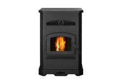
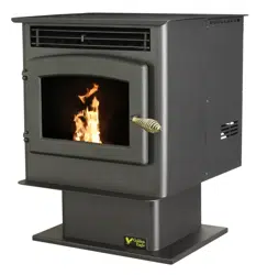
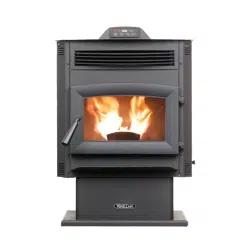
P43-C, P61-C & P68-C
Freestanding Pellet Stove
NOTICE: SAVE THESE INSTRUCTIONS
To obtain a French translation of this manual, please
contact your dealer or visit www.harmanstoves.com
Pour obtenir une traduction française de ce manuel, s’il
vous plaît contacter votre revendeur ou visitez www.
harmanstoves.com
NOTE
Hot glass will cause burns.
• Do not touch glass until it is cooled
• NEVER allow children to touch glass
• Keep children away
• CAREFULLY SUPERVISE children in same room as
stove.
• Alert children and adults to hazards of high temperatures.
High temperatures may ignite clothing or other
ammable materials.
• Keepclothing,furniture,draperiesandotherammable
materials away.
HOT SURFACES!
Glass and other surfaces are hot
during operation AND cool down.
WARNING
Please read this entire manual before
installation and use of this pellet fuel-
burning room heater.
Failure to follow these instructions could
result in property damage, bodily injury
or even death.
• Donotstoreorusegasolineorotherammablevapors
and liquids in the vicinity of this or any other appliance.
• Donotoverre-Ifanyexternalpartstartstoglow,you
areoverring.Reducefeedrate.Overringwillvoid
your warranty.
• Comply with all minimum clearances to combustibles
asspecied.Failuretocomplymaycausehousere.
WARNING
Check building codes prior to installation.
• Installation MUST comply with local, regional, state and
national codes and regulations.
• Contactlocalbuildingorreocialsaboutrestrictions
and installation inspection requirements in your area.
CAUTION

Harman® • P-Series Installation Manual_R12 • 06/252 8390-044I
TABLE OF CONTENTS
Safety Alert Key:
• DANGER! Indicates a hazardous situation which, if not avoided will result in death or serious injury.
• WARNING! Indicates a hazardous situation which, if not avoided could result in death or serious injury.
• CAUTION! Indicates a hazardous situation which, if not avoided, could result in minor or moderate injury.
• NOTICE: Indicates practices which may cause damage to the stove or to property.
Installation Standard Work Checklist ............... 3
1 Product Specic and Important Safety Information
A.ApplianceCertication .......................4
B.GlassSpecications .........................4
C. Mobile Home Approvals ......................4
D. California Safety Information ..................4
E.BTUSpecications ..........................5
F. Non-CombustibleMaterialsSpecication .........5
G.CombustibleMaterialsSpecication ............. 5
H. Electrical Codes ............................5
2 Getting Started
A. Design and Installation Considerations ..........6
B. Tools and Supplies Needed ...................7
C. Inspect Appliance and Components .............7
3 Framing and Clearances
A. Appliance Dimension Diagram .................8
B. Clearances to Combustibles ................... 9
C. Floor Protection ...........................10
D. Mobile Home Installation ....................10
4 Termination Location and Vent Information
A. Vent Termination Minimum Clearances ......... 11
B. Chimney Diagram ..........................15
C. Venting & Use of Elbows ....................16
D.OutsideAir ...............................18
E. Locating Your Appliance and Chimney ..........19
F. Draft ....................................19
G. Negative Pressure .........................19
H.AvoidingSmoke&Odors ....................20
I. Fire Safety ...............................21
J. Inspect Appliance & Components .............. 21
5 Appliance Setup
A. Unpacking ................................ 22
B. Removing Rear Cover Panels ................22
C. Firebrick .................................22
D. Flame Guide ..............................22
E. Room Sensor .............................23
F. Low Draft Voltage Adjustment .................23
6 Reference Materials
A. Safety Reminders ..........................24
B. Wiring Diagram ............................25
= Contains updated information
Harman® • P-Series Installation Manual_R12 • 06/253 8390-044I
Installation Standard Work Checklist
ATTENTION INSTALLER:
Follow this Standard Work Checklist
This standard work checklist is to be used by the installer in conjunction with, not instead of, the instructions contained in
this installation manual.
Customer: ________________________________ Date Installed: __________________________
Lot/Address: ________________________________ Location of Stove: __________________________
________________________________ Installer: __________________________
Model: ________________________________ Dealer/Distributer Ph # __________________________
Serial Number: __________________________
WARNING! Risk of Fire or Explosion! Failure to install appliance to these instructions can lead to a re
or explosion.
Appliance Install
Section 3 YES IF NO, WHY?
Requirednon-combustibleoorprotection ________________________________
Veriedclearancestocombustible. ________________________________
UnitisLeveledandsecured. ________________________________
Venting/Chimney Section 4
VentingCongurationcompliestoventdiagrams. ________________________________
Ventinginstalled,sealedandsecuredinplacewithproperclearances. ________________________________
Exteriorwall/roofashinginstalledandsealed ________________________________
Terminationsinstalledandsealed. ________________________________
Electrical Section 1
120VACunswitchedpowerprovidedtotheappliance. ________________________________
Checkoutletwithmulti-meterforpropervoltage.(115-120VAC) ________________________________
Recordvoltagereading:___________
Appliance Setup Section 5
Allpackagingandprotectivematerialsareremoved ________________________________
Accessoriesinstalledproperly ________________________________
Manual bag and all it’s contents are removed from inside the appliance
andgiventopartyresponsibleforuseandoperation ________________________________
Startedapplianceandveriedthatallmotorsandblowersoperate
astheyshould. ________________________________
CheckeddraftusingaManometer.Recordreadings:__________ ________________________________
Duringoperation,verifythatthehopperlidswitch(Ifapplicable)
andpressureswitchareworkingproperlybybrieyopeningthehopper
lidandmaindoorandverifyingthatthefeedmotorisinterrupted. ________________________________
Hearth and Home Technologies recommends the following:
Photographingtheinstallationandcopyingthischecklistforyourle.
This checklist remain visible at all times on the appliance until the installation is complete.
Comments:Furtherdescriptionoftheissues,whoisresponsible(Installer/Builder/OtherTrades,etc.)andcorrectiveaction
needed__________________________________________________________________________________________
_________________________________________________________________________________________________
_________________________________________________________________________________________________
Commentscommunicatedtopartyresponsible____________________by________________________on__________
(Builder/GenContractor)(Installer) (Date)
04/23
Harman® • P-Series Installation Manual_R12 • 06/254 8390-044I
A. Appliance Certication B. Glass Specications
This appliance is equipped with 5mm mirrored ceramic
glass. Replace glass only with 5mm ceramic glass. Please
contact your dealer for replacement glass.
C. Mobile Home Approved
This appliance is approved for mobile home installations
when not installed in a sleeping room and when an outside
combustion air inlet is provided.
Thestructuralintegrityofthemobilehomeoor,ceiling,and
walls must be maintained. The appliance must be properly
grounded to the frame of the mobile home and use only listed
pellet vent, Class “PL” connector pipe.
A Harman
®
OutsideAirKitmustbeinstalledinamobilehome
installation.
NOTE: This installation must conform with local codes.
In the absence of local codes you must comply with the
ASTM E1509, ULC-S627-00, ULC/ORD-C-1482-M1990,
(UM) 84-HUD
1 1
Product Specic and Important Safety Information
MODEL: P43-CPelletStove
LABORATORY: OMNITestLaboratories,Inc
REPORT NO. 0135PS023E/0135PS023S
TYPE: PelletFueled/SupplementaryFor
Residential Use
STANDARD(s): ASTME1509,ULC-S627-00,ASTM
E2515-11,ASTME2779-10
MODEL: P61-CPelletStove
LABORATORY: OMNITestLaboratories,Inc
REPORT NO. 0135PS022E/0135PS022S
TYPE: PelletFueled/SupplementaryFor
Residential Use
STANDARD(s): ASTME1509,ULC-S627-00,ASTM
E2515-11,ASTME2779-10
MODEL: P68-CPelletStove
LABORATORY: OMNITestLaboratories,Inc
REPORT NO. 0135PS013E/0135PS013S
TYPE: PelletFueled/SupplementaryFor
Residential Use
STANDARD(s): ASTME1509,ULC-S627-00,ASTM
E2515-11,ASTME2779-10
THE STRUCTURAL INTEGRITY OF THE
MANUFACTURED HOME FLOOR, WALL, AND
CEILING/ROOF MUST BE MAINTAINED.
DO NOT INSTALL IN SLEEPING ROOM.
WARNING
!
WARNING
This product and the fuels used to operate this product
(wood),andtheproductsofcombustionofsuchfuels,can
expose you to chemicals including carbon black, which
is known to the State of California to cause cancer, and
carbonmonoxide,whichisknowtotheStateofCalifornia
to cause birth defects or other reproductive harm. For
more information go to: www.P65Warnings.ca.gov
D. California Safety Information
The P43-C, P61-C and P68-C is Certied
to comply with 2020 particulate emission
standards.
Harman® • P-Series Installation Manual_R12 • 06/255 8390-044I
NOTE: Hearth & Home Technologies, manufacturer of
this appliance, reserves the right to alter its products, their
specicationsand/orpricewithoutnotice.
Harman
®
is a registered trademark of Hearth & Home
Technologies.
F. Non-Combustible Materials Specication
Material which will not ignite and burn. Such materials are
those consisting entirely of steel, iron, brick, tile, concrete,
slate, glass or plasters, or any combination thereof.
Materials that are reported as passing ASTM E 136,
Standard Test Method for Behavior of Materials in
a Vertical Tube Furnace at 750° C and UL763 shall be
considerednon-combustiblematerials.
G. Combustible Materials Specication
Materials made of or surfaced with wood, compressed
paper,plantbers,plastics,orothermaterialthatcanignite
andburn,whetherameproofedornot,orplasteredorun-
plastered shall be considered combustible materials.
H. Electrical Codes
120 VAC, 60 Hz, Start 4.2 Amps, Run 2.8 Amps
NOTE: Some generator or battery back-up systems may
not be compatible with the micro-processor electronics
on this appliance. Please consult the power supply
manufacturer for compatible systems.
WARNING! Risk of Fire! Hearth & Home Technologies
disclaims any responsibility for, and the warranty and agency
listing will be voided by the below actions.
DO NOT:
• Install or operate damaged appliance
• Modify appliance
• Install other than as instructed by Hearth & Home
Technologies
• Operate the appliance without fully assembling all
components
• Overre
• Install any component not approved by Hearth &
Home Technologies
• Install parts or components not Listed or approved.
• Disable safety switches
Improper installation, adjustment, alteration, service or
maintenance can cause injury or property damage.
Forassistanceoradditionalinformation,consultaqualied
installer, service agency or your dealer.
E. BTU & Eciency Specications
*WeightedaverageLHVeciencyusingdatacollected
during EPA emissions test.
**WeightedaverageHHVeciencyusingdatacollected
during EPA emissions test.
***ArangeofBTUoutputsbasedonEPADefaultEciency
and the burn rates from the low and high EPA tests.
****Based on the maximum feed rate per hour multiplied by
approximately 8,600 BTU’s which is the average BTU’s from
a pound of pellets.
This wood heater needs periodic inspection and repair for
proper operation. It is against federal regulations to operate
this wood heater in a manner inconsistent with operating
instructions in this manual.
P43-C Freestanding Pellet Stove:
EPA Certication Number: 165-18
EPA Certied Emissions: 1.82g/hr
*LHV Tested Eciency: 82.7%
**HHV Tested Eciency: 76.7%
***EPA BTU Output: 18,780-33,250
****BTU Input: 23,900-45,200
Vent Size: 3 Inch
Hopper Capacity: 50 lbs
Fuel Wood Pellet
P61-C Freestanding Pellet Stove:
EPA Certication Number: 177-19
EPA Certied Emissions: 1.5g/hr
*LHV Tested Eciency: 85%
**HHV Tested Eciency: 79%
***EPA BTU Output: 17,100-46,800
****BTU Input: 21,400-60,700
Vent Size: 3 Inch
Hopper Capacity: 72 lbs
Fuel Wood Pellet
P68-C Freestanding Pellet Stove:
EPA Certication Number: 178-19
EPA Certied Emissions: 1.4g/hr
*LHV Tested Eciency: 85%
**HHV Tested Eciency: 79.5%
***EPA BTU Output: 15,900-53,100
****BTU Input: 20,200-67,600
Vent Size: 3 Inch
Hopper Capacity: 76 lbs
Fuel Wood Pellet
Harman® • P-Series Installation Manual_R12 • 06/256 8390-044I
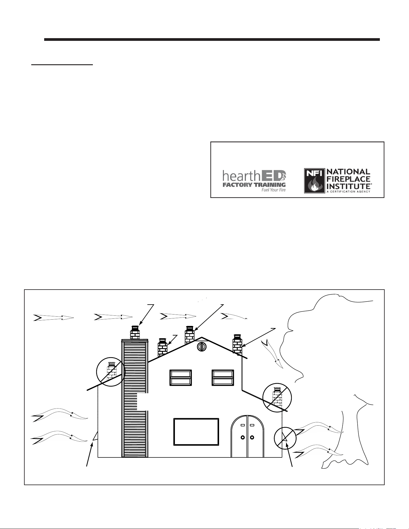
A. Design and Installation Considerations
1. Appliance Location
NOTICE: Check building codes prior to installation.
• Installation MUST comply with local, regional, state
and national codes and regulations.
• Consult insurance carrier, local building inspector,
re ocials or authorities having jurisdiction over
restrictions, installation inspection and permits.
Itisagoodideatoplanyourinstallationonpaper,usingexact
measurementsfor clearances and oor protection,before
actually beginning the installation
Consideration must be given to:
• Safety,convenience,tracow
• Placement of the chimney and chimney connector.
• If you are not using an existing chimney, place the
appliance where there will be a clear passage for a
factory-built listed chimney through the ceiling and
roof.
• Installinganoptionaloutside air kit wouldaectthe
location of the vent termination.
Sincepelletexhaustcan containash,sootorsparks,you
must consider the location of:
• Windows
• Air Intakes
• Air Conditioner
• Overhang,sots,porchroofs,adjacentwalls
• Landscaping, vegetation
Marginal Location:
• Below peak
Location NOT recommended:
• Not the highest point of the roof
• Wind loading possible
Multi-level Roofs
Windward
Leeward
Recommended:
Outside Air Intake
on windward side
NOT recommended:
Outside Air Intake
on leeward side
Recommended Location:
• Above peak
Recommended:
• Insulated exterior chase
in cooler climates
Recommended Location:
• Above peak
• Inside heated space
Location NOT recommended:
• Too close to tree
• Below adjacent structure
• Lower roof line
• Avoid outside wall
Marginal Location:
• Wind loading possible
Figure 2.1
2 2
Getting Started
When locating vent and venting termination, vent above
roof line when possible.
Warning! Risk of Fire Damaged parts could impair safe
operation. Do NOT install damaged, incomplete or substitute
components.
NOTICE: Locating the appliance in a location of considerable
air movement can cause intermittent smoke spillage from
appliance. Do not locate appliance near:
• Frequently open doors
• Central heat outlets or returns
Installation and service of this appliance should be performed by
qualiedpersonnel.Hearth&HomeTechnologiesrecommends
HHTFactoryTrainedorNFIcertiedprofessionals.
Harman® • P-Series Installation Manual_R12 • 06/257 8390-044I
Reciprocating Saw
Hammer
Phillips Screwdriver
Tape Measure
Level
Non-CombustibleSealant
Material
Gloves
Safety Glasses
Electric Drill & Bits
May also need:
Vent Support Straps
Venting Paint
Tools and building supplies normally required
for installation, unless installing into an existing
masonry replace:
B. Tools And Supplies Needed
C. Inspect Appliance and Components
• Carefully remove the appliance and components from
the packaging.
• The vent system components and decorative doors
and fronts may be shipped in separate packages.
• Report to your dealer any parts damaged in shipment,
particularly the condition of the glass.
• Read all of the instructions before starting the
installation. Follow these instructions carefully
during the installation to ensure maximum safety
and benet.
Hearth & Home Technologies disclaims any responsibility
for, and the warranty will be voided by the following actions:
• Installation and use of any damaged appliance or
vent system component.
• Modicationoftheapplianceorventsystem.
• Installation other than as instructed by Hearth &
Home Technologies.
• Installationand/oruseofanycomponentpartnot
approved by Hearth & Home Technologies.
Any such action may cause a re hazard.
WARNING
Risk of Fire, Explosion or Electric Shock! DO NOT use
this appliance if any part has been under water. Call a
qualied service technician to inspect the appliance
and to replace any part of the control system which
has been under water.
INSTALL EXHAUST VENT AT CLEARANCES SPECIFIED
BY THE MANUFACTURER.
Most pellet vent pipe requires a minimum of 1" of clearance
to combustible materials although some can be installed at
1" clearance.
Follow these instructions along with all local codes regarding
installation of this appliance.
Do NOT use makeshift compromises when installing this
appliance, serious consequences may result.
WARNING
RISK OF FIRE OR EXPLOSION! Damaged parts
could impair safe operation. DO NOT install damaged,
incomplete or substitute components. Keep appliance
dry.
Harman® • P-Series Installation Manual_R12 • 06/258 8390-044I
3 3
Clearances
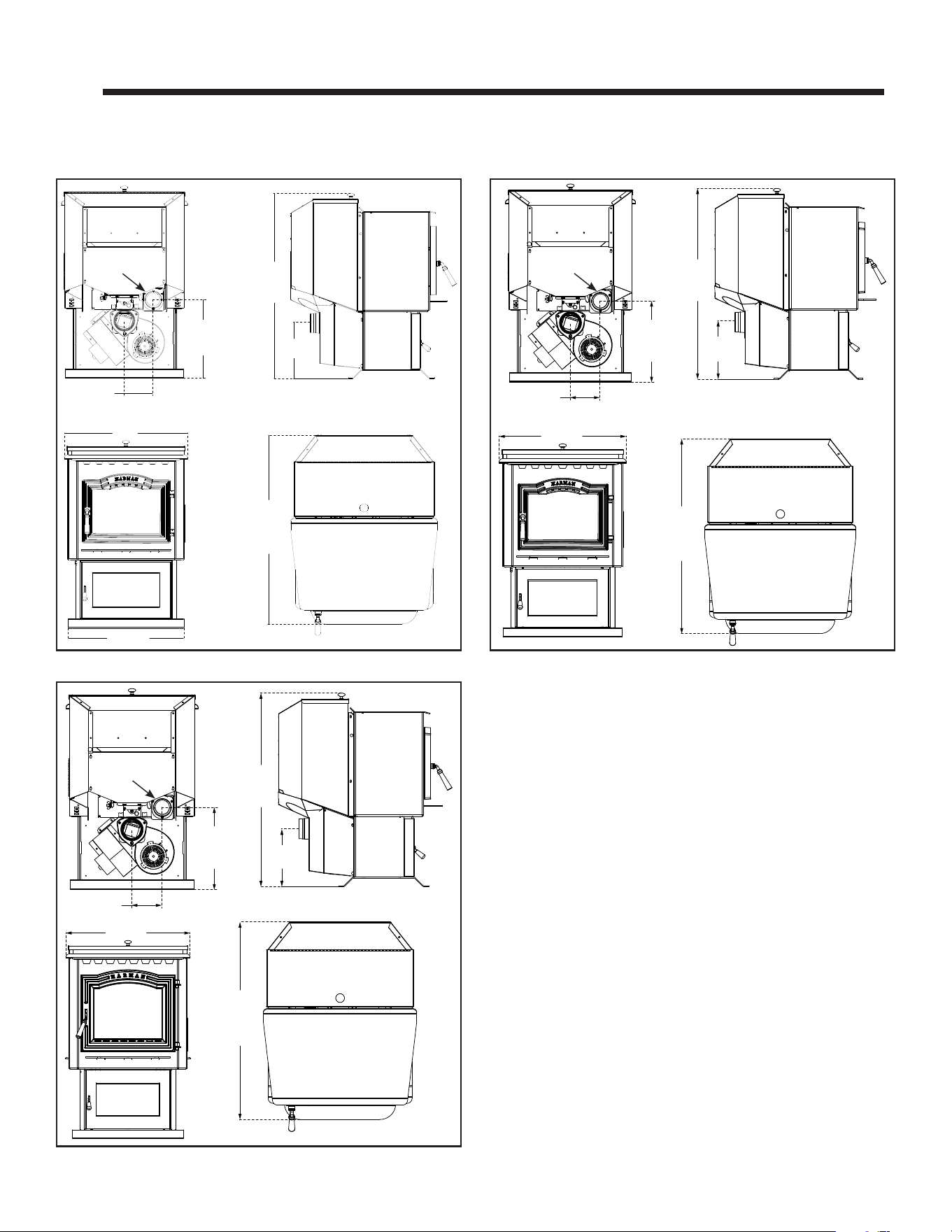
A. Appliance Dimension Diagram
Dimensions are actual appliance dimensions. Use for reference only.
Figure 3.1
20 3/4"
22"
10"
33 1/2"
5 1/8"
13 3/4"
28 5/16"
Outside
Air Intake
P43-C Freestanding Pellet Stove
23 1/2"
10 "
36 1/2"
5 1/8"
13 3/4”
29 3/8"
Outside
Air Intake
P61-C Freestanding Pellet Stove
10 "
37 1/2”
5 1/4"
13 3/4”
29 3/8"
23-1/2”
Outside
Air Intake
P68-C Freestanding Pellet Stove
Harman® • P-Series Installation Manual_R12 • 06/259 8390-044I
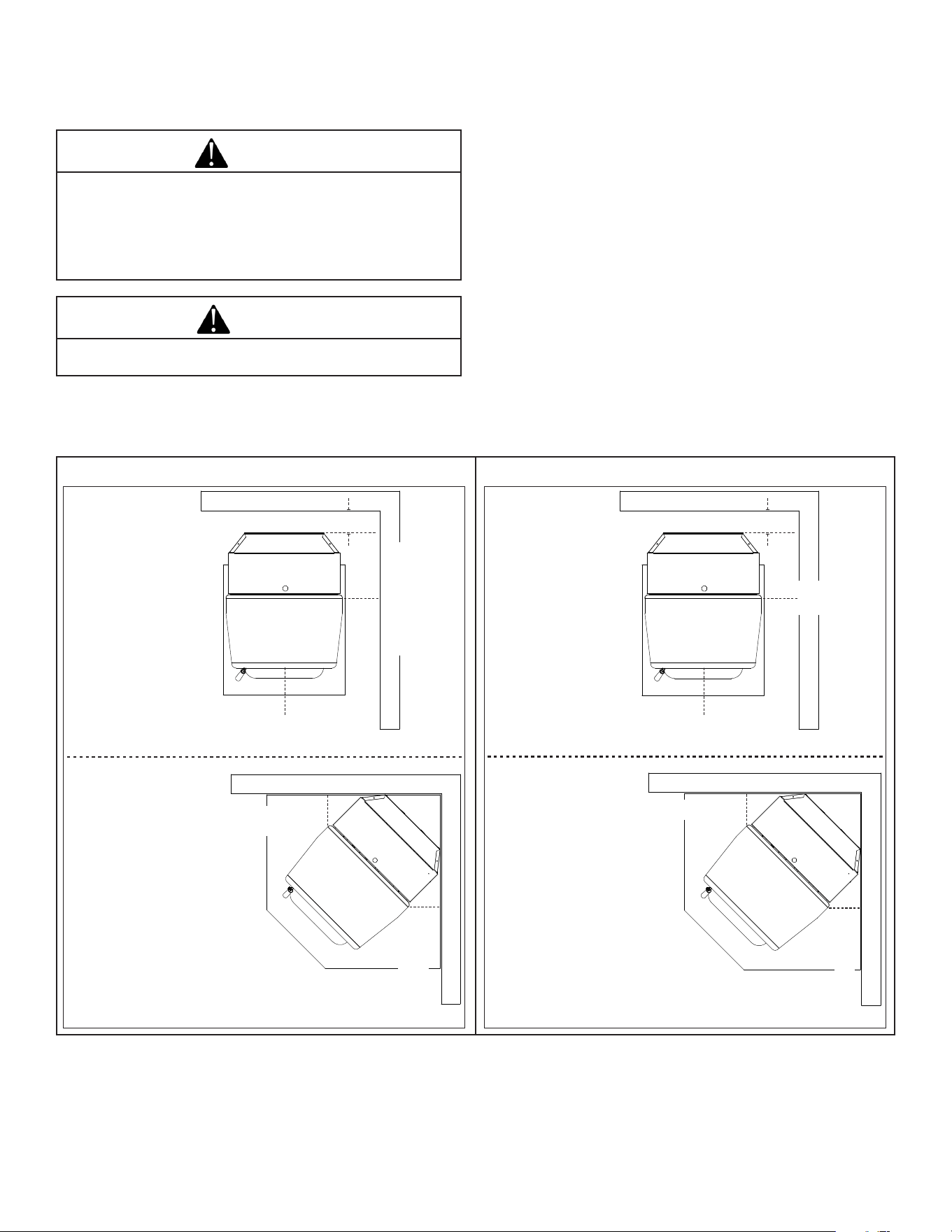
Place the stove away from combustible walls at least as far
asshowninFigure3.2.Pleasenotethedierenceinside
wall clearance with and without side shields.
Note that the clearances shown are minimum for safety but do
not leave much room for access when cleaning or servicing.
Please take this into account when placing the stove.
Due to high temperatures, the stove should be placed out of
tracandawayfromfurnitureanddraperies.
Children and adults should be alerted to the hazards of high
surface temperatures and should stay away to avoid burns
toskinand/orclothing.
Young children should be carefully supervised when they are
in the same room as the stove.
Clothingandotherammablematerialsshouldnotbeplaced
on or near this unit.
B. Clearances to Combustibles
When selecting a location for the appliance it is important to
consider the required clearances to walls, Figure 3.2.
CAUTION
THIS APPLIANCE MUST BE VENTED TO THE OUTSIDE.
WARNING
RISK OF FIRE OR BURNS! Provide adequate
clearance around air openings and for service
access. Due to high temperatures, the appliance should
be located out of trac and away from furniture and
draperies.
NOTICE: IllustrationsreecttypicalinstallationsandareFOR
DESIGNPURPOSESONLY.Actualinstallationmayvarydue
to individual design preference.
Figure 3.2
9"(228mm)With Side Shields
13"(330mm) Without Side Shields
9"(228mm)-
13"(330mm)
9"(228mm)-
13"(330mm)
9" (228mm) With or Without Side Shields
9"(228mm)
9"(228mm)
*10" (254mm) with
side shields
*16" (406mm)
without side shields
2" (51mm)
36" (914mm)
*10" (254mm)
*16" (406mm)
2" (51mm)
36" (914mm)
P68-C
14" (355mm)
20" (508mm)
P61-C
12” (305mm)
18” (457mm)
P68-C
14" (355mm) with
side shields
20" (508mm)
without side shields
P61-C
12” (305mm) with side
shields
18” (457mm)
without side shields
P43-C Freestanding Pellet StoveP61-C & P68-C Freestanding Pellet Stove
Harman® • P-Series Installation Manual_R12 • 06/2510 8390-044I
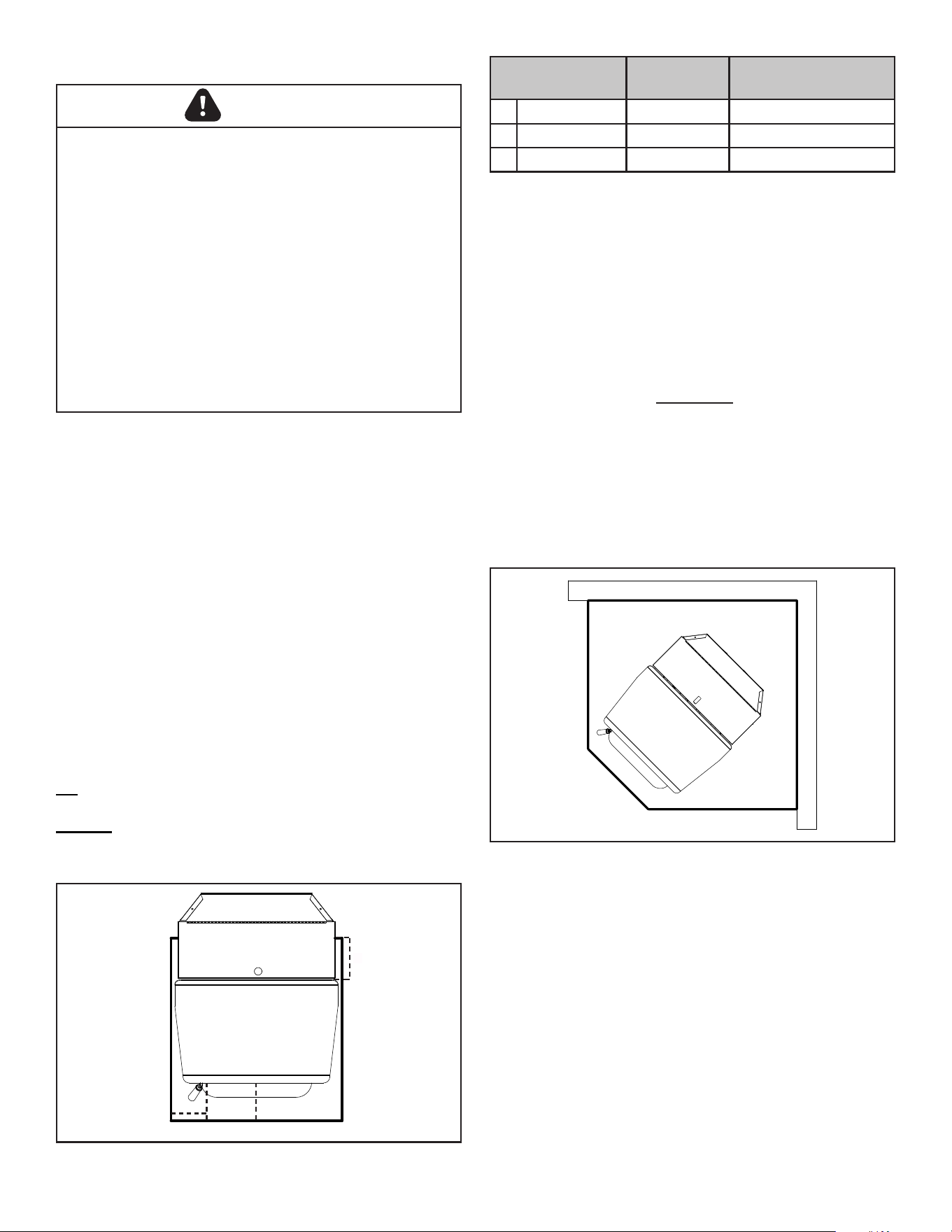
C. Floor Protection
Figure 3.3
J
K
L
Floor Protector
D. Mobile Home Installation
When installing this unit in a mobile home, several
requirements must be followed:
1. The unit mustbeboltedto the oor.Thiscanbe done
using an appropriate fastener for the application.
2. The unit must also be connected to outside air. See
“Termination Location and Vent Information” Section D.
3. Floor protection and clearances must be followed as
shown.
4. The appliance must be properly grounded to the frame of
the mobile home using a minimum of 8 AWG copper solid
or stranded, insulated or bare wire or equivalent.
Floor Protection
Requirements
US Canada
J Sides 6" 152mm
K Front 6” 152mm
L Rear 6” 152mm
Corner Installation:
Minimumsizeoorprotectionforacornerinstallationhearth
pad is:
P43-C-Minimumsizeoorprotectionis25-7/16”Wideby
26-3/4”Deep(646mmX680mm).
P61-C- Minimum size oor protection is25-1/8”Wide by
27-3/4”Deep(638mmX705mm).
P68-C-Minimumsizeoorprotectionis25-3/16”Wideby
27-3/4”Deep(640mmX705mm).
Note: Floor protector WILL NOT touch the wall using
minimum clearances.
If corner oor protection is desired to touch the wall, the
oorprotectionwillneedtobeatleast40”x40”(1016mm
x1016mm).Note: This will allow the oor protection to
touch the wall as shown. Figure 3.4.
Alternateoorprotectordimensionmaybeusedaslongas
they satisfy the measurement requirements shown below.
Figure 3.4
Parallel Installation:
Place the stove on a noncombustible type oor or oor
protectorthatextendsaminimumof6inches(152mm)to
thefrontoftheloaddooropening,6inches(152mm)tothe
sides of the door opening, and 6 inches to the rear.
TheP-SeriesdoesnotrequireRvalueoorprotection.
Theminimumoorprotectormaterialis20gaugesheetmetal.
OtheroorprotectormaterialsthatcanbeusedincludeType
I hearth pads, ceramic tile, stone, brick, etc. Figure 3.3
*Floor protection dimensions for the front and sides are
measured from the appliance door opening and the rear is
measured by the pedistal base rear edge.
P43-C - Minimum size rectangular oor protection is 25-
7/16”Wideby26-3/4”Deep(646mmX680mm).
P61-C-Minimumsizerectangularoorprotectionis25-1/8”
Wideby27-3/4”Deep(638mmX705mm).
P68-C - Minimum size rectangular oor protection is 25-
3/16”Wideby27-3/4”Deep(640mmX705mm).
Venting:
US-Follow PL vent manufacturers recommendations when
conguringventpipeinstallation.
Canada-Mustextend2”(51mm)beyondeachsideofany
horizontaluepipe.
CAUTION
Hearth and Home Technologies does not recommend adhesive
based vinyl ooring due to thermal expansion. Floating-style
ooring(LVP-luxuryvinylplankorLVT–luxuryvinyltile)canbe
used, but it will reach temperatures up to 110 °F in a room with
ambienttemperatureof70°F.Consultooringspecicationsto
ensure compatibility.
HHT recommends wood stoves and inserts have 29 inches of
alternativeooringinfrontofthestovebeforeusingLVP/LVT
regardless if they sit ush on the oor or are elevated on a
raised hearth.
Forallotherooring,continuetofollowclearancetocombustible
requirements in the installation manual.
NOTICE: Clearances that do not meet the minimum guidelines
couldresultindamageorbucklingtothevinylooringandis
done at the installer’s or homeowner’s risk.
Harman® • P-Series Installation Manual_R12 • 06/2511 8390-044I
4 4
Termination Location and Vent Information
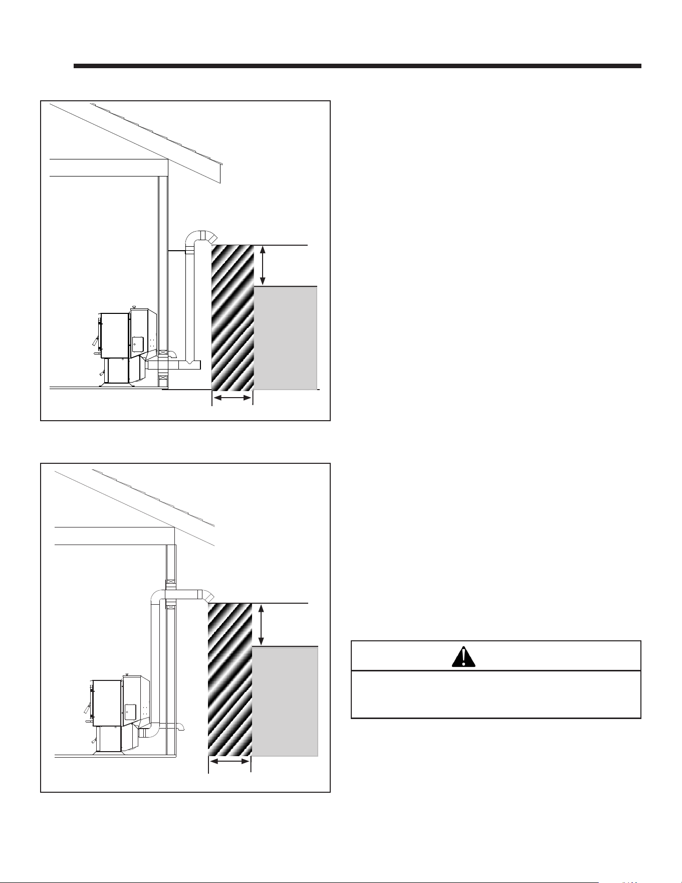
A. Vent Termination Minimum Clearances
Figure 4.1
Figure 4.2
Note: Follow venting manufacturer’s recommendations for
sealing pipe joints.
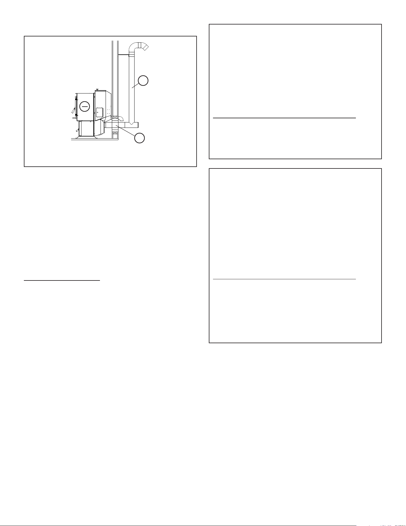
#1 Preferred method (Figure 4.1)
Thismethodprovidesexcellentventingfornormaloperation
and allows the stove to be installed closest to the wall. Two
inches from the wall is safe; however, four inches allows
better access to remove the rear panel. The vertical portion of
theventshouldbethreetovefeethigh.Thisverticalsection
will help provide natural draft in the event of a power failure.
Do not place joints within wall pass-through.
#2 Preferred method (Figure 4.2)
This method also provides excellent venting for normal
operation but requires the stove to be installed farther from
the wall. The vertical portion of the vent should be three to
vefeethighandatleast1”fromacombustiblewall.This
vertical section will provide natural draft in the event of a
power failure.
If the stove is installed below grade be sure the vent
termination is at least 12" above grade. The outlet must also
be 1 foot from the house/building.
Do not place joints within wall pass-through.
CAUTION
Keep combustible materials (such as grass, leaves,
etc.) at least 3 feet away from the ue outlet on the
outside of the building.
3 Ft.
to
Combustibles
3 Ft.
to Combustibles
3 Ft.
to
Combustibles
3 Ft.
to Combustibles
Harman® • P-Series Installation Manual_R12 • 06/2512 8390-044I
Figure 4.3
Figure 4.4
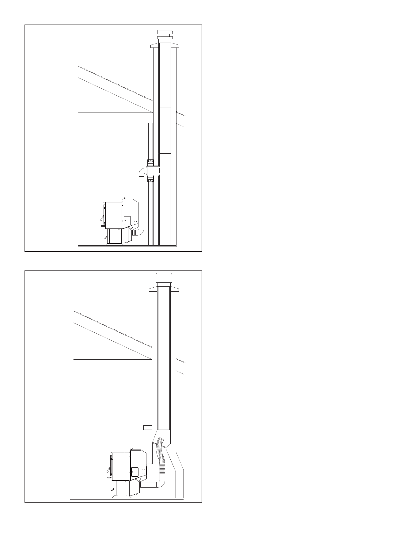
#3 Installing into an existing chimney (Figure 4.3)
Thismethodprovidesexcellentventingfornormaloperation.
This method also provides natural draft in the event of a
power failure. If the chimney condition is questionable* you
may want to install a liner as in method #7.
In some places in the US and Canada it is required that the
ventpipeextendallthewaytothetopofthechimney.
*The chimney should be inspected and cleaned before
installing your stove. If you discover that the chimney does
nothaveaclaytilelinerorhascracksorakingofthetile
liner you will need to install a stainless steel liner within
the chimney. In most cases the inside diameter of this liner
shouldbe4".Eitherexibleorrigidlinermaybeusedforthis
purpose. Refer to Method 6 & 7.
Be sure to design the venting so that it can be easily cleaned.
#4 Installing into an existing replace chimney (Figure 4.4)
Thismethodprovidesexcellentventingfornormaloperation.
This method also provides natural draft in the event of a
power failure. If the chimney condition is questionable* you
may want to install a liner as in method #6.
In some places in the US and Canada it is required that the
ventpipeextendallthewaytothetopofthechimney.
*The chimney should be inspected and cleaned before
installing your stove. If you discover that the chimney does
nothaveaclaytilelinerorhascracksorakingofthetile
liner you will need to install a stainless steel liner within
the chimney. In most cases the inside diameter of this liner
shouldbe4".Eitherexibleorrigidlinermaybeusedforthis
purpose. Refer to Method 5 & 6.
Note:Thedamperareaofthereplacemustbesealedwith
ametalplate.It isrecommendedtouseanon-ammable
insulation such as mineral wool or ceramic to insulate the
top of the plate to avoid condensation. Do not use high
temperature caulking materials to seal any edge which could
prevent future serviceability or removal.
Be sure to design the venting so that it can be easily cleaned.
Harman® • P-Series Installation Manual_R12 • 06/2513 8390-044I
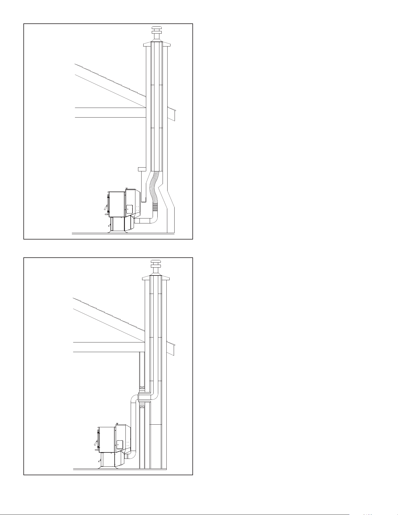
#5 Installing into an existing replace chimney (Figure
4.5) w/Full Liner
Thismethodprovidesexcellentventingfornormaloperation.
This method also provides natural draft in the event of a
power failure.
In some places in the US and Canada it is required that the
ventpipeextendallthewaytothetopofthechimney.The
pipe or liner inside the chimney should be 4" diameter.
In this method a cap should also be installed on the chimney
to keep out rain. Be sure to use approved pellet vent pipe
ttings.Pipesizeshouldbeincreasedto4"usingthismethod.
#6 Installing into an existing chimney (Figure 4.6) w/Full liner
Thismethodprovidesexcellentventingfornormaloperation.
This method also provides natural draft in the event of a
power failure.
In some places in the US and Canada it is required that the
ventpipeextendallthewaytothetopofthechimney.The
pipe or liner inside the chimney should be 4" diameter.
In this method a cap should also be installed on the chimney
to keep out rain.
Figure 4.5
Figure 4.6
Harman® • P-Series Installation Manual_R12 • 06/2514 8390-044I
12"
min. wall to outlet
36"
min. clearance to any
combustible material
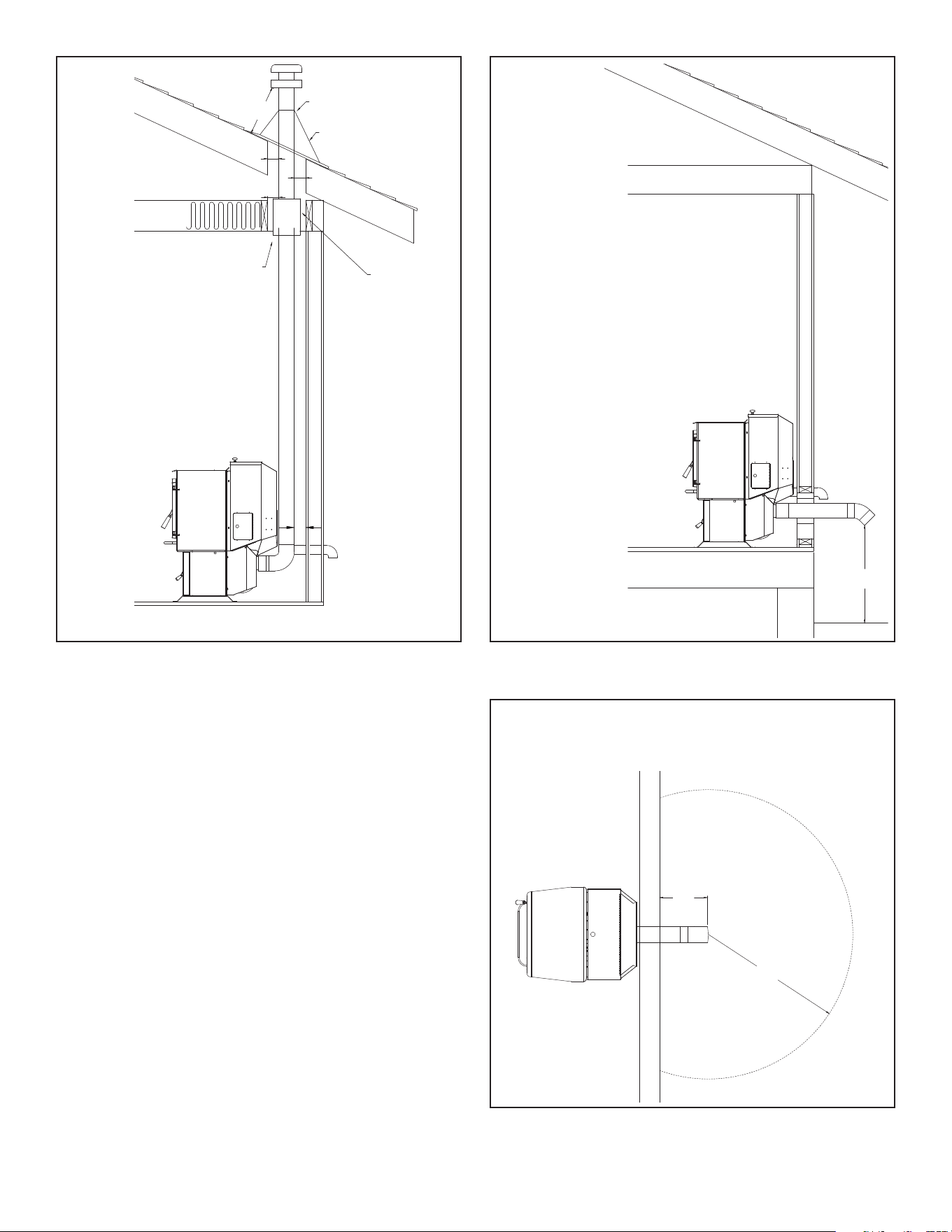
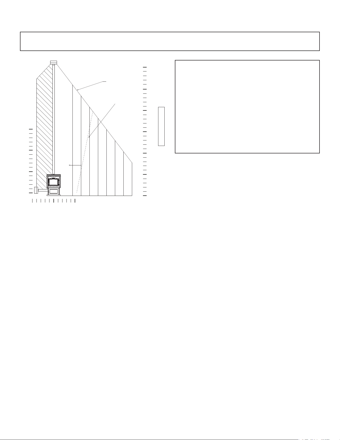
#7 Installing through the ceiling
Through the ceiling vent, follow PL vent manufacturers
recommendations when using wall and ceiling pass through.
Do not place joints within wall pass-through.
Figure 4.7 Figure 4.8
Figure 4.9
Area within dotted circle represents the minimum
clearance to combustible materials such as shrubbery,
mulch or tall grasses.
12"
min. above ground level
Minimum ue vent conguration
It is recommended that outside
air be installed with this venting
conguration.
PL vent manufacturer's
restop spacer and support
1" MIN.
No insulation or other
combustible materials
are allowed within 3"
of the PL vent pipe.
ashing
storm collar
1" MIN.
1" MIN.
12" MIN
1” MIN.
Harman® • P-Series Installation Manual_R12 • 06/2515 8390-044I
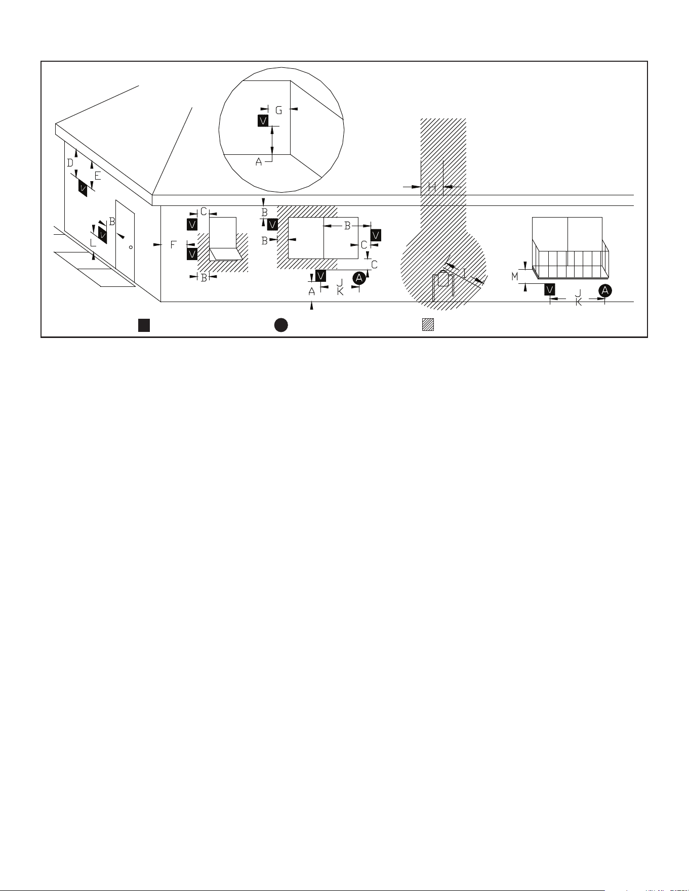
B. Chimney Diagram
V
=Vent Terminal
A
=Air Supply Inlet
=Area where termination is not permitted
Door
Sidewalk
Fixed
Closed
Openable
Openable
Fixed
Closed
Inside Corner
Detail
Porch or
Openable
Deck
or Fixed
Requirements for Terminating the Venting
• Venting terminals must not be recessed into a wall
or siding.
• Only PL vent pipe wall pass-through and re stops
should be used when venting through combustible
materials.
• Always take into consideration the effect the
prevailing wind direction or other wind currents will
cause with yash and /or smoke when placing the
termination.
In addition, the following must be observed:
A. The clearance above grade must be a minimum of 12".
B. The clearance to a window or door that may be opened
must be a minimum of 48" to the side and 48" below the
window/door, and 12" above the window/door. (with
outside air installed, 12” to side and below)
C. A 12" clearance to a permanently closed window is
recommended to prevent condensation on the window.
D. Theverticalclearancetoaventilatedsotlocatedabove
theterminalwithinahorizontaldistanceof2feet(60cm)
fromthecenter-lineoftheterminalmustbeaminimum
of 18".
E. The clearance to an unventilated soffit must be a
minimum of 12".
F. The clearance to an outside corner is 11" from center of
pipe.
G. The clearance to an inside corner is 12".
H. Aventmustnotbeinstalledwithin3feet(90cm)above
agasmeter/regulator assemblywhenmeasuredfrom
thehorizontalcenter-lineoftheregulator.
Figure 4.10
I. The clearance to service regulator vent outlet must be a
minimum of 6 feet.
J. Theclearancetoanon-mechanicalairsupplyinlettothe
building or the combustion air inlet to any other appliance
must be a minimum of 48”.
K. The clearance to a mechanical air supply inlet must be a
minimumof10feet.(with outside air installed, 6 feet)
L. The clearance above a paved sidewalk or a paved
driveway located on public property must be a minimum
of 7 feet.
M. The clearance under a veranda, porch, deck or balcony
must be a minimum of 12 inches. (B. also)
Note: The clearance to vegetation and other exterior
combustibles such as mulch is 36” as measured from
the center of the outlet or cap. This 36” radius continues
to grade.
Certain Canadian and or Local codes or regulations may
requiredierentclearances.
A vent shall not terminate directly above a side-walk or
paved driveway which is located between two single family
dwellings and serves both dwellings.
Onlypermittedifveranda,porch,deck, or balcony is fully
openonaminimumof2sidesbeneaththeoor.
See NFPA 211 for more installation clearance reductions
when using outside air. Where passage through a wall,
or partition of combustible construction is desired,
the installation shall conform to CAN/CSA-B365. (if in
Canada)
Harman® • P-Series Installation Manual_R12 • 06/2516 8390-044I
Harman pellet stoves depend on a combustion fan to pull air
through the unit for combustion. The venting system restricts
the ability of the combustion fan to move the required amount
of air through the unit. A system with too much resistance
will result in incomplete combustion, more frequent required
cleaning and poor unit performance. It is always best to
choose a location for the appliance that will result in a venting
systemwiththeshortestequivalentventlength(EVL).
It is best to have your venting system designed by a Harman
authorizeddealerbeforeyounalize your purchase of an
appliance.
Equivalent Vent Length: The equivalent vent length for
common pellet vent components are:
• 90° Elbows or Tee: 5 EVL Units
• 45° elbow: 3 EVL Units
• Vertical Pipe or Liner: ½ EVL Unit
• Horizontal Pipe or liner: 1 EVL Unit
The total allowable equivalent vent length is:
• 20 EVL for 3” pellet vent pipe or liner
• 30 EVL for 4” pellet vent pipe or liner
Duetothepotentialfor y ash accumulation in horizontal
ventingsections,themaximumpermissiblehorizontalventing
length is:
• 4 ft. for 3” & 4” pellet vent pipe.
C. Venting & Use of Elbows
O
+
= Positive static pressure
= Negative static pressure
O
-
Figure 4.11
+
+
Example: First Floor Installation
A unit is to be installed using 3” Pellet Pipe with 3 feet
of horizontal pipe, a Tee, 10 feet of vertical pipe, a 90°
elbow and a termination cap.
The equivalent vent length is:
3ft.ofHorizontalPipe(1x3EVL) =3EVL
90°ElboworTee(1xEVL) =5EVL
10ft.ofVerticalPipe(10x.5EVL) =5EVL
90°ElboworTee(1xEVL) =5EVL
TerminationCap =0EVL
EquivalentVentLength =18EVL
Intheexamplesystemdetailedabove,theEVLwas138
whichislessthanthemaximumof20EVLfor3”pellet
ventpipe,thusthisisasatisfactoryventingconguration.
Example: Connection to Masonry Chimney
A unit is to be installed using 3” Pellet Pipe with 2 feet of
horizontal pipe, a Tee, 4 feet of vertical pipe, an elbow, a
Tee, 21 feet of vertical liner, and a termination cap.
The equivalent vent length is:
2ft.ofHorizontalPipe(1x2EVL) =2EVL
90°Tee(1x5EVL) =5EVL
4ft.ofVerticalPipe(4x.5EVL) =2EVL
90°Elbow(1x5EVL) =5EVL
90°Tee(1x5EVL) =5EVL
21ft.ofVerticalLiner(21x.5EVL) =10.5EVL
TerminationCap =0EVL
EquivalentVentLength =29.5EVL
In the example system detailed above, the EVL was
29.5whichexceedsthemaximumof20ft.for3”pellet
vent pipe, thus 3” vent pipe should not be used in this
installation. However, since 4” pipe can support an EVL
up to 30, the use of 4” pipe would create a satisfactory
installation.
Harman® • P-Series Installation Manual_R12 • 06/2517 8390-044I
C. Venting & Use of Elbows continued
Note:Whentheamountofverticalpelletventpipeinthesystemexceeds15feet,4”pelletventpipeshouldbeused.
Note: Equivalent Venting Length decreases as altitude increases.
Example:
A unit with an EVL of 13, is to be installed at an altitude
of 3,000 feet above sea level.
From the chart to the left, at 3,000 feet of altitude, the
maximum permissible equivalent venting length is 26
feet. Therefore this would be an acceptable installation
with no need to change the combustion blower fan.
However, if the same unit (EVL 13)was to be installed
an altitude of 9,000 feet above sea level, the installation
would no longer be acceptable and the equivalent vent
length of the pipe would have to be reduced for proper
unit operation.
No Change of Combustion
Blower Fan Blade Needed
0 Ft5 Ft 5 Ft
10,000
9,000
8,000
7,000
6,000
5,000
4,000
3,000
5 Ft
0 Ft
10 Ft
Combustion Blower Fan
Blade Changeover Line
Altitude
10 Ft
15 Ft
20 Ft
25 Ft
30 Ft
5 Ft
0 Ft
15 Ft
Equivalent Vent Length (EVL)
Maximum Horizontal Run
• LongrunsofexorPLventpipeinstalleddirectlyverticalfromtheuestubmayrequiremorefrequentcleaningdueto
yashfallingoinsideandcollectingdirectlyabovethecombustionbloweroutlet.
• 4" stainless steel ex vent piping is only allowed for use in masonry replaces and chimneys or factory built wood-
burningreplaceswithClassAmetalchimneys.
• All pellet vent pipe must be secured together either by means provided by pipe manufacturer or by 3 screws at each joint.
• Useonlythespeciedventingcomponents.Useofanyothercomponentswillvoidtheproductwarrantyandmaypose
a hazard.
• DoNotInstallaFlueDamperInTheExhaustVentingSystemofThisAppliance.
• DONOTCONNECTTHISUNITTOACHIMNEYFLUESERVINGANOTHERAPPLIANCE.
• NOTE:SimpsonDuraVentPelletVentProHarman®AdapterPart#3PVP-ADHBandPelletVentProHarman®Adapter
Increaser Part #3PVPX4ADHB are highly recommended to be installed on the starter collar to insure a proper pipe
connection to the unit.
• INSTALL VENT AT CLEARANCES SPECIFIED BY THE VENT MANUFACTURER
• Usesiliconetocreateaneectivevaporbarrieratthelocationwherethechimneyoroutsideairductingpassesthrough
totheexteriorofthestructure
Harman® • P-Series Installation Manual_R12 • 06/2518 8390-044I
Outside Air:
Hearth & Home Technologies recommend attaching
outside air in all installations, especially lower level and
main oor locations.
Per national building codes, consideration must be given to
combustion air supply to all combustion appliances. Failure
to supply adequate combustion air for all appliance demands,
mayleadtoback-draftingofthoseandotherappliances.
Whentheapplianceisside-wallvented:Theairintakeisbest
locatedonthesameexteriorwallastheexhaustventoutlet
andlocatedloweronthewallthantheexhaustventoutlet.
When the appliance is roof vented: The air intake is best
locatedontheexteriorwallorientedtowardstheprevailing
wind direction during the heating season.
The outside air connection will supply the demands of the
pellet appliance, but consideration must be given to the
total house demand. House demand may consume some
air needed for the stove, especially during a power failure. It
may be necessary to add additional ventilation to the space in
which the pellet appliance is located. Consult with your local
HVAC professional to determine the ventilation demands for
your house.
Toinstalloutsideairuse3".non-combustibleexpipeFigure
4.13.Thereisabreak-awayholeontherearpanelofthe
P-Seriesstovewhichmustberemovedbeforeconnecting
theexpipe.Figure4.12.Thepipeshouldberunoutsideand
terminatetothesideorbelowtheventpipeoutletsotheue
outlet is more than 12" from the inlet cover. The Termination
Cap should be used to keep birds, rodents, etc. out of the
pipe Figure 4.13.
YoumaychoosetousetheoptionalDirectVentWallPass-
throughKitwhichincorporatestheventingpass-throughand
outside air inlet into one component. Figure 4.14.
Use silicone to create an eective vapor barrier at the
location where the chimney or outside air ducting passes
through to the exterior of the structure.
D. Outside Air
Direct Vent Wall Pass-through Kit
(Part#1-00-677177)
Figure 4.14
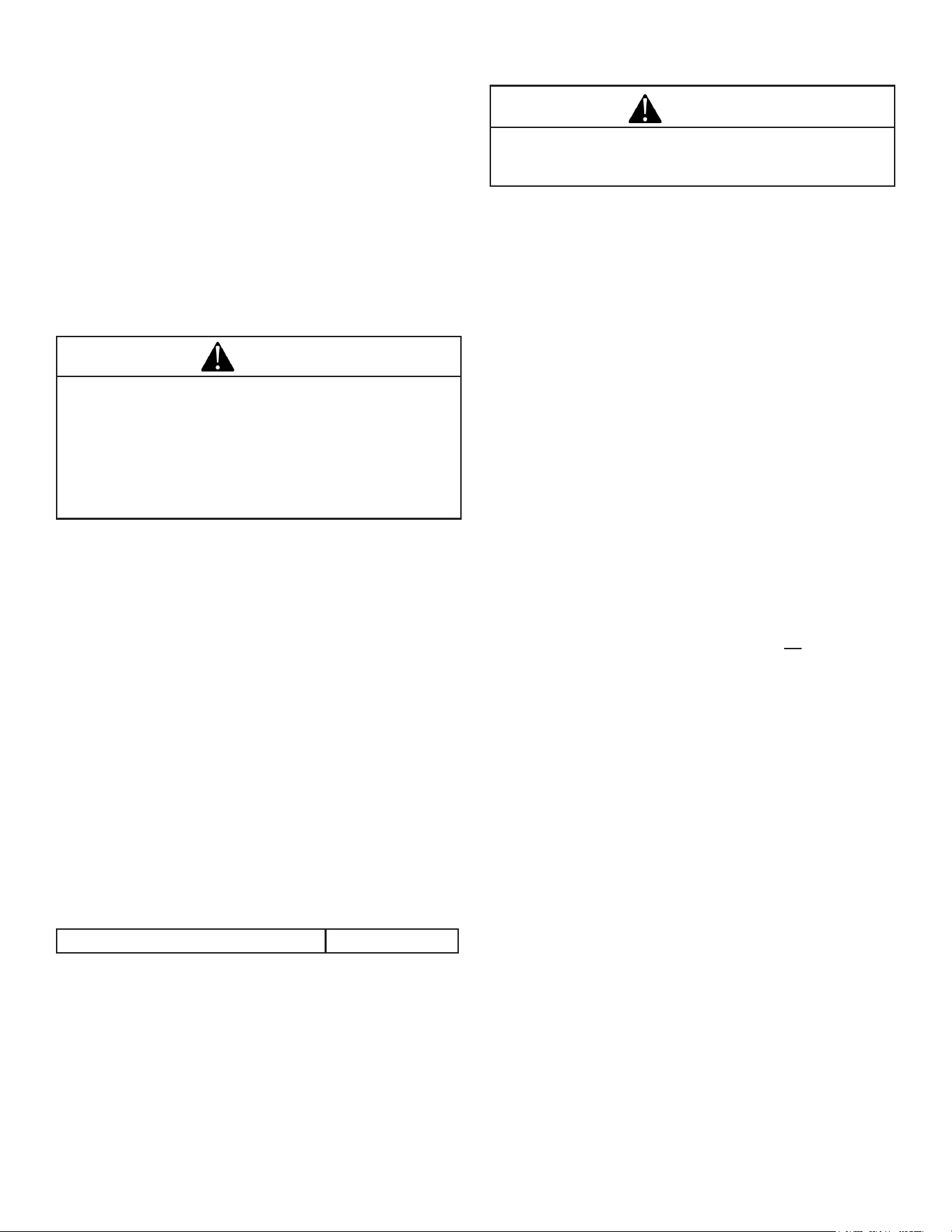
Termination Cap
part#1-10-09542
Figure 4.13
Outsideairex
pipe goes here.
Figure 4.12
Harman® • P-Series Installation Manual_R12 • 06/2519 8390-044I
E. Locating Your Appliance & Chimney
Locationoftheapplianceandchimneywillaectperformance.
• Install through the warm airspace enclosed by the
building envelope. This helps to produce more draft,
especiallyduringlightinganddie-downofthere.
• Penetrate the highest part of the roof. This minimizes the
eectsofwindloading.
• Locate termination cap away from trees, adjacent
structures, uneven roof lines and other obstructions.
• Minimizetheuseofchimneyosets.
• Consider the appliance location relative to oor and
ceiling and attic joists.
G. Negative Pressure
F. Draft
Draftisthepressuredierenceneededtoventappliances
successfully. When an appliance is drafting successfully, all
combustionbyproductsareexiting the home through the
chimney.
Considerations for successful draft include:
• Preventing negative pressure
• Location of appliance and chimney
To measure the draft or negative pressure on your appliance
use a magnahelic or a digital pressure gauge capable of
reading0-1inchesofwatercolumn(W.C.).
The appliance should be running on high for at least 15
minutes for the test.
With the stove running on high you should have a negative
pressure equal to or greater than the number given in the
chartbelow.Ifyouhavealowerreadingthanyoundonthe
chart, your appliance does not have adequate draft to burn
the fuel properly.
Minimum Vacuum Requirements: .35 - .55
Priortoinstallingtheuepipe,connectadraftmeter.(The
draftmetermusthaveaminimumrangeof0-.5”)Recordthe
rstreading.Connectuepipetostoveandbesurealldoors
and windows in the home are closed. Record the second draft
reading_______.If thesecondreading is morethan.05”
lowerthantherstreading,checkforpossiblerestrictions
or the need for outside air. For more information on the draft
test procedure, refer to Page 21
• DONOTCONNECTTHISUNITTOACHIMNEYFLUE
SERVICINGANOTHERAPPLIANCE.
• DO NOT CONNECTTOANYAIR DISTRIBUTION
DUCTORSYSTEM.
Mayallowuegasestoenterthehouse
CAUTION
Negative pressure results from the imbalance of air available
for the appliance to operate properly. It can be strongest in
lower levels of the house.
Causes include:
• Exhaustfans(kitchen,bath,etc.)
• Range hoods
• Combustion air requirements for furnaces, water heaters
and other combustion appliances
• Clothes dryers
• Locationofreturn-airventstofurnaceorairconditioning
• Imbalances of the HVAC air handling system
• Upper level air leaks such as:
-Recessedlighting
-Attichatch
-Ductleaks
Tominimizetheeectsofnegativeairpressure:
• Install the outside air kit with the intake facing prevailing
winds during the heating season
• Ensure adequate outdoor air for all combustion
appliancesandexhaustequipment
• Ensure furnace and air conditioning return vents are not
located in the immediate vicinity of the appliance
• Avoid installing the appliance near doors, walkways or
small isolated spaces
• Recessed lighting should be a “sealed can” design
• Attic hatches weather stripped or sealed
• Attic mounted duct work and air handler joints and
seams taped or sealed
NOTICE: Hearth & Home Technologies assumes no
responsibility for the improper performance of the chimney
system caused by:
• Inadequate draft due to environmental conditions
• Downdrafts
• Tight sealing construction of the structure
• Mechanical exhausting devices
Risk of Asphyxiation! Negative pressure can cause
spillage of combustion fumes and soot.
WARNING

Harman® • P-Series Installation Manual_R12 • 06/2520 8390-044I
H. Avoiding Smoke and Odors
Negative Pressure, Shut-down, and Power Failure:
To reduce the probability of back-drafting or burn-back in
the pellet burning appliance during power failure or shut-
down conditions, the stove must be able to draft naturally
withoutexhaustbloweroperation.Negativepressureinthe
house will resist this natural draft if not accounted for in the
pellet appliance installation.
Heat rises in the house and leaks out at upper levels. This
airmustbereplacedwithcoldairfromoutdoors,whichows
into lower levels of the house. Vents and chimneys into
basements and lower levels of the house can become the
conduit for air supply, and reverse under these conditions.
Outside Air
An outside air kit is recommended in all installations. The
OutsideAirKitmustbeorderedseparately.
Per national building codes, consideration must be given to
combustion air supply to all combustion appliances. Failure
to supply adequate combustion air for all appliance demands
may lead to back drafting of those and other appliances.
Whentheapplianceisroofvented(stronglyrecommended):
Theairintakeisbestlocatedontheexteriorwalloriented
towards the prevailing wind direction during the heating
season.
Whentheapplianceisside-wallvented:
Theairintakeisbestlocatedonthesameexteriorwall
astheexhaustventoutletandlocatedloweronthewall
thantheexhaustventoutlet.
The outside air supply kit can supply most of the demands
of the pellet appliance, but consideration must be given to
the total house demand.
House demand may consume the air needed for the
appliance. It may be necessary to add additional ventilation
to the space in which the pellet appliance is located.
Consult with your local HVAC professional to determine the
ventilation demands for your house.
Vent Pipe
Be sure to use approved pellet vent pipe wall and ceiling
pass-throughttingstogothroughcombustiblewallsand
ceilings. Be sure to use a starting collar to attach the venting
system to the stove. The starting collar must be secured to
theuestubwithatleastthreescrews,andsealedwithhigh
temp silicone caulking.
4” stainless steel ex vent piping is only allowed for use
in masonry replaces and chimneys orfactory built wood
burningreplaceswithclassAmetalchimneys.
Pelletventingpipe(alsoknownasTypeLvent)isconstructed
of two layers with air space between the layers. This air
space acts as an insulator and reduces the outside surface
temperature to allow a clearance to combustibles of only
1 inch. The sections of pipe lock together to form an air
tight seal in most cases. Follow venting manufacturer’s
recommendations for sealing pipe joints.
Wherepassingthroughanexteriorwallorroof,besuretouse
theappropriatepass-throughdeviceprovidinganadequate
vapor barrier. Venting manufacturers generally provide these
pass-throughdevices.
Vent Congurations:
To reduce probability of reverse drafting during shut-
down conditions, Hearth & Home Technologies strongly
recommends:
• Installing the pellet vent with a minimum vertical run of
vefeet,preferablyterminatingabovetheroofline.
• Installing the outside air intake at least four feet below
the vent termination.
Topreventsootdamagetoexteriorwallsofthehouseand
topreventre-entryofsootorashintothehouse:
• Maintainspeciedclearancestowindows,doors,and
air inlets, including air conditioners.
• Ventsshouldnotbeplacedbelowventilatedsots.Run
the vent above the roof.
• Avoid venting into alcove locations.
• Vents should not terminate under overhangs, decks or
onto covered porches.
• Maintain minimum clearance of 12 inches from the
ventterminationtotheexteriorwall.Ifyouseedeposits
developingon thewall,you mayneedto extendthis
distance to accommodate your installation conditions.
Hearth & Home Technologies assumes no responsibility
for, nor does the warranty extend to, smoke damage
caused by reverse drafting of pellet appliances under
shut-down or power failure conditions.
Harman® • P-Series Installation Manual_R12 • 06/2521 8390-044I
I. Fire Safety
To provide reasonable re safety, the following should be
given serious consideration:
• InstallatleastonesmokedetectorandCOdetectoron
eachoorofyourhome.
• Locate smoke detector away from the heating appliance
and close to the sleeping areas.
• Follow the smoke detector manufacturer’s placement and
installation instructions and maintain regularly.
• ConvenientlylocateaClassAreextinguishertocontend
withsmallres.
• Intheeventofahopperre:
• Evacuate the house immediately.
• Notifyredepartment.
J. Inspect Appliance & Components
• Remove appliance and components from packaging
and inspect for damage.
• Report to your dealer any parts damaged in shipment.
• Read all the instructions before starting the
installation. Follow these instructions carefully
during the installation to ensure maximum safety
and benet.
• Installation and use of any damaged appliance.
• Modicationoftheappliance.
• Installation other than as instructed by Hearth & Home
Technologies.
• Installationand/oruseofanycomponentpartnotapproved
by Hearth & Home Technologies.
• Operating appliance without fully assembling all
components.
• DoNOTOverre.
Or any such action that may cause a re hazard.
Fire Risk.
Hearth & Home Technologies disclaims any
responsibility for, and the warranty will be voided
by the following actions:
Inspect appliance and components for damage.
Damaged parts may impair safe operation.
• DoNOTinstalldamagedcomponents.
• DoNOTinstallincompletecomponents.
• DoNOTinstallsubstitutecomponents.
Report damaged parts to dealer.
WARNING
WARNING
This wood heater needs periodic inspection and repair for
proper operation. It is against federal regulations to operate
this wood heater in a manner inconsistent with operating
instructions in this manual.
WARNING
THIS WOOD HEATER HAS A MANUFACTURER-
SET MINIMUM LOW BURN RATE THAT MUST
NOT BE ALTERED. IT IS AGAINST FEDERAL
REGULATIONS TO ALTER THIS SETTING OR
OTHERWISE OPERATE THIS WOOD HEATER IN
A MANNER INCONSISTENT WITH OPERATING
INSTRUCTIONS IN THIS MANUAL.
Harman® • P-Series Installation Manual_R12 • 06/2522 8390-044I
5 5
Appliance Set-Up
A. Unpacking
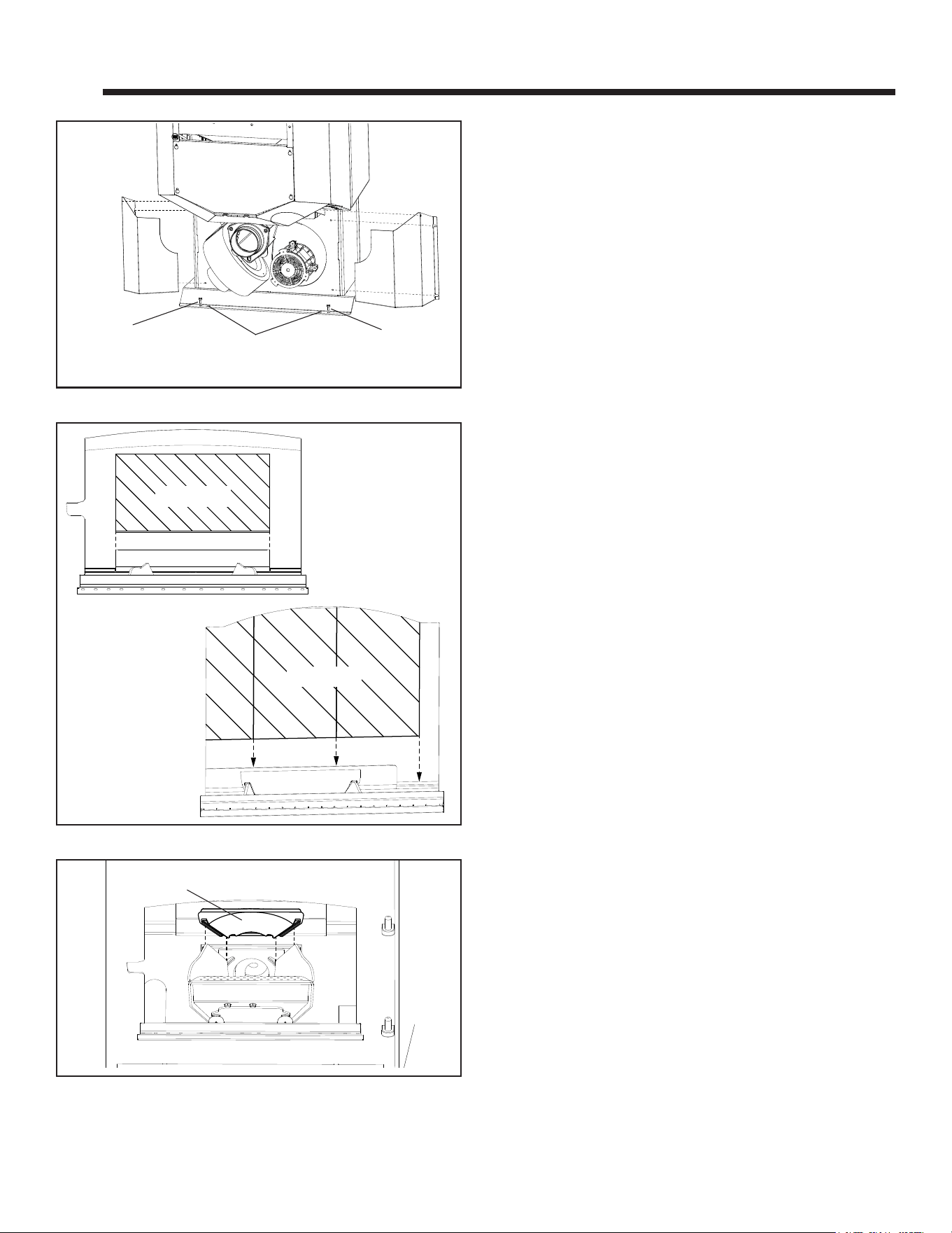
TheP-Seriesisbolted(1/4x1"hexheadbolts)totheskid
to prevent movement during shipping.
Tofreethestovefromtheskidyoumustremovethehold-
downboltsintherearof the pedestal base using a 7/16”
socket or wrench. Figure 5.1.
B. Removing Rear Cover Panels
The rear cover panels are secured to the stove with three
screws each. Two of the screws need only be loosened, not
removed, to remove the panels. It is recommended that the
rearcoversareinstalledusinga5/16”socket,wrenchornut
driver after the unit is in place and the vent pipe is installed,
to prevent contact with hot or moving parts.
Ifneeded,installthe(2)5/16-18X3/4”levelingboltslocated
in the hardware kit. Figure 5.1.
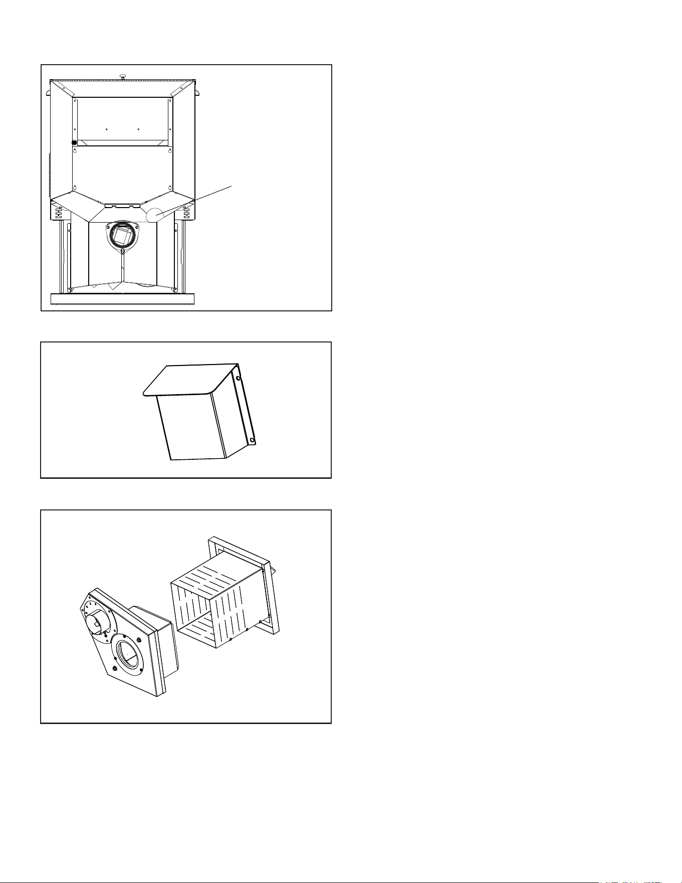
C. Firebrick
TheP43-CPelletStovehasasingle(1)rebrickthatgets
installed horizontally on the angle bracket above the burnpot.
The P61-C and P68-C have three (3) rebrick that get
installed vertically on the angle bracket. Figure 5.2.
D. Flame Guide
Installthecastironameguideontopoftheburnpot.Make
surethattheameguideisfullyseatedontheverticalsides
of the burn pot and that the back of the guide rests against
the body of the stove. Figure 5.3.
Figure 5.3
Flame guide
Figure 5.2
1 Firebrick
P43-C Pellet Stove
3 Firebrick
P61-C & P68-C
Pellet Stove
Figure 5.1
Rear Cover
Panel
Shipping Bolts
Note: These same holes are used for
securing the stove in mobile home
installation.
Rear Cover
Panel
Leveling Bolt
Leveling
Bolt
Harman® • P-Series Installation Manual_R12 • 06/2523 8390-044I
E. Room Sensor Installation
The room sensor is a small temperature sensor on the end of
a 60" wire. This sensor is installed much like a standard wall
thermostat. There is a remote room sensor port on the rear
oftheunitforeasyexternalconnection.Usestandard18-2
thermostatwiretoextendthesensortothedesiredlocation
(50'maximum).Theroomsensorshouldbeinstalledinthe
location where you want to control the temperature.
NOTE: Distances of more than 25 feet from the unit or in
another room are not recommended. The room sensor is
essentialfortheP-Seriesexcellenteciency.
NOTE: It is recommended that the room sensor be installed,
even if only installed on the rear of the unit as a return air
sensor.
F. Low Draft Voltage Adjustment
Theseunitsarepre-testedatthe factory with exactly 120
VAC, 60 Hz. They are checked and adjusted for rebox
tightness, gasket leakage, motor operation and igniter
operation.TheP-Series is then factory set at a mid-point
adjustment and in most cases will not need any adjustments.
NOTE: The factory low draft setting may not be correct
for the unit’s permanent installation conditions.
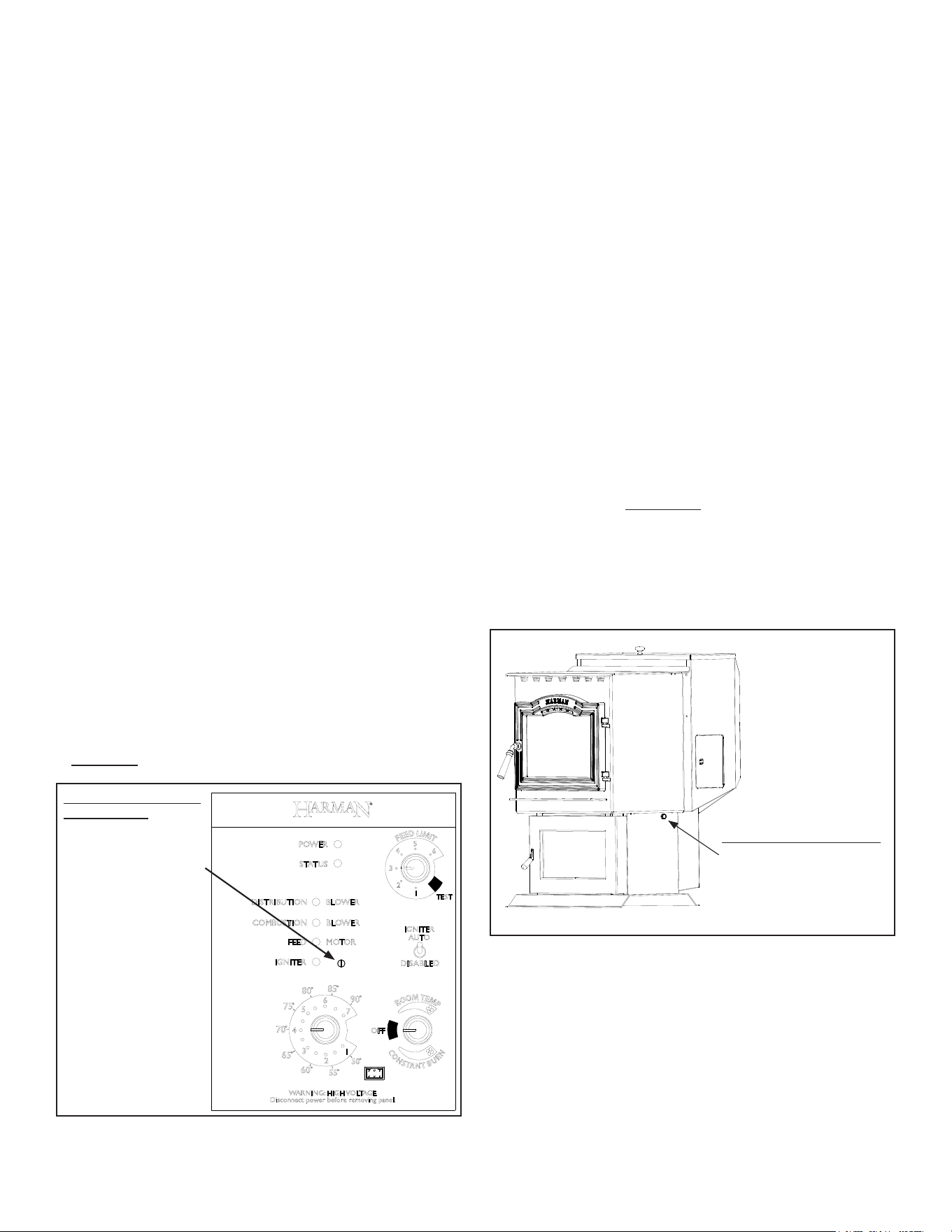
Thecontrolboard ontheP-Seriesis equippedwithalow
draft adjustment port located on the control face just to the
right of the igniter light. Figure 5.4. This voltage adjustment
is provided to allow the unit to be adjusted for the household
voltage where the unit is going to be in permanent operation.
NOTE: The line voltage varies from area to area and often
home to home.
The low draft voltage should be adjusted to achieve the most
ecient burn on low burn or “maintenance”. This voltage
adjustment allows the installer to change the low voltage set
pointapproximately10volts.Thisadjustmentshouldbedone
by the installer during set up because a draft meter reading
is required to insure proper set up.
If the unit is not adjusted properly, it does not cause a safety
concern.Iftheunitisadjustedtoohigh,onlyeciencyislost.
If the unit is adjusted too low, the low draft pressure switch
will not allow the feed motor or the igniter to operate.
A simple draft test should be performed after completing the
uepipeinstallation.Torecordtheresultsforfuturereference:
1. Plug unit into a 120 VAC, 60 HZ outlet.
2. Close the hopper lid, front view door, and the ash pan
door.Neitherpelletsorarearerequiredforthistest.
3. Withthemodeselectorinthe“OFF”position,turnthefeed
adjuster to “TEST”.
4. Record the high draft_____in W.C. (Normal is -.50 to
-.60)ThecontrolwillbeontheHighDraftforatotalof2
minutes.
5. After 1 minute, the combustion motor will go down to low
draft and the distribution blower will go on high. Allow
approximately 15 seconds to pass for the combustion
motor to slow before checking the low draft.
6. Ifthelowdraftisbetween-.35and-.45,recordthereading
_____ in W.C. If the reading is higher, slowly turn the
setscrewcounter-clockwiseuntilthedraftlowers.Ifthe
reading is lower, very slowly turn the set screw clockwise
until the draft increases.
NOTE: In some cases, the draft may not go as low as
-.35 to -.45 even with the set screw completely counter-
clockwise. Ideally, you should just set it as low as
possible.
Connect the power cord to a 120 VAC, 60 Hz grounded
receptacle. (A surge protector is recommended to protect
thecircuitboard.)Alsobesurethatthepolarityoftheoutlet
that the stove is plugged into is correct.
Draft Meter bolt hole location
On a P-Series the draft test hole is
undertheleftrearcorneroftherebox
on the pedestal base.
Figure 5.5
Combustion Motor
Speed Control
Low draft only set point.
The small straight
screwdriver slot is plastic;
therefore, the unit can
be adjusted while in
operation.
Figure 5.4
Harman® • P-Series Installation Manual_R12 • 06/2524 8390-044I
6 6
Reference Material
A. Safety Reminders
When installing and operating your Harman
®
P-Series,
respect basic safety standards. Read these instructions
carefullybeforeyouattempttoinstalloroperatetheP-Series.
Failure to do so may result in damage to property or personal
injury and may void the product warranty.
Consult with your local building code agency and insurance
representative before you begin your installation to ensure
compliance with local codes, including the need for permits
andfollow-upinspections.
WARNING
MOBILE/MANUFACTURED HOME GUIDELINES DO
NOT ALLOW INSTALLATION IN A SLEEPING ROOM.
WARNING
KEEP COMBUSTIBLE MATERIALS SUCH AS
GRASS, LEAVES, ETC. AT LEAST 3 FEET AWAY
FROM THE POINT DIRECTLY UNDER THE VENT
TERMINATION.
WARNING
USE OF IMPROPER FUELS, FIRESTARTERS OR
ALTERING THE STOVE FOR HIGHER HEAT OUTPUT
MAY CAUSE DAMAGE TO THE STOVE AND COULD
RESULT IN A HOUSE FIRE. USE ONLY APPROVED
FUELS AND OPERATION GUIDELINES
THE STOVE IS HOT WHILE IN OPERATION.
KEEP CHILDREN, CLOTHING AND FURNITURE
AWAY. CONTACT MAY CAUSE SKIN BURNS.
CAUTION
THE STRUCTURAL INTEGRITY OF THE MOBILE
HOME FLOOR, WALL, AND CEILING/ROOF MUST BE
MAINTAINED.
CAUTION
Due to high temperatures, this stove should be placed out of
tracandawayfromfurnitureanddraperies.
Children and adults should be alerted to the hazards of high
surface temperatures and should stay away to avoid burn
toskinand/orclothing.
Young children should be carefully supervised when they are
in the same room as the stove.
Clothingandotherammablematerialsshouldnotbeplaced
on or near this stove.
Installation and repair of this stove should be done by a
qualiedserviceperson.Theapplianceshouldbeinspected
beforeuseandatleastannuallybyaqualiedserviceperson.
More frequent cleaning may be required. It is imperative
that control compartments, burners, and circulating air
passageways of this stove be kept clean.
CAUTION
This appliance must be vented to the outside.
BURNING COLORED PAPER, CARDBOARD,
SOLVENTS, TRASH AND GARBAGE OR ALTERING
THE STOVE FOR HIGHER HEAT OUTPUT MAY
CAUSE DAMAGE TO THE STOVE AND COULD
RESULT IN A HOUSE FIRE. USE ONLY APPROVED
FUELS AND FOLLOW ONLY THESE OPERATION
GUIDELINES.
WARNING
WHEN THIS ROOM HEATER IS NOT PROPERLY
INSTALLED, A HOUSE FIRE MAY RESULT. TO
REDUCE THE RISK OF FIRE, FOLLOW THE
INSTALLATION INSTRUCTIONS. CONTACT
LOCAL BUILDING OR FIRE OFFICIALS ABOUT
RESTRICTIONS AND INSTALLATION INSPECTION
REQUIREMENTS IN YOUR AREA.
CAUTION
Harman® • P-Series Installation Manual_R12 • 06/2525 8390-044I
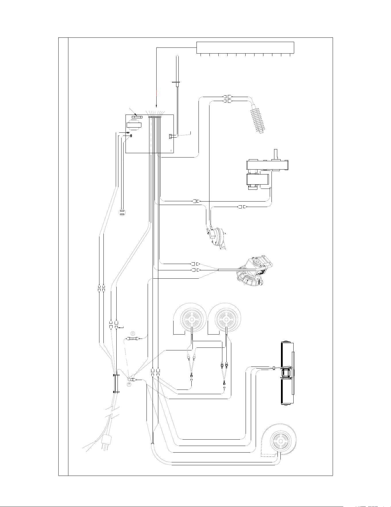
B. Wiring Diagram
HARMAN ACCENTRA/P35i/P40i/P43/P61/P68/XXV/52i PELLET STOVE WIRING DIAGRAM
WHITE 11 PIN PLUG
PART # 3-90-94734
4
8
6
5
11
10
9
1
3
CONTROL BOARD
18/3 CORD
LT.BLUE
LT.BLUE
18/3 POWER CORD
GREEN WIRE IS GROUND
BONDED TO STOVE BODY
GREEN
GREEN
WHITE
WHITE
DK BLUE
RED
WHITE
WHITE
BROWN
RO0M SENSOR PORT
BLACK
YELLOW
RED 10
BLACK 11
BROWN
PLUGGED
YELLOW
EMPTY
DK BLUE
WHITE
WHITE
WHITE
WHITE
7
8
9
5
6
3
2
4
1
TWISTED WIRE
ESP
ESP PROBE
PRESSURE SWITCH
NO CONTACTS
COMBUSTION MOTOR
FEED MOTOR
IGNITER ELEMENT
P43, P61, P68
DISTRIBUTION BLOWER
WHITE OR LT BLUE
GREEN USED ON ACCENTRA ONLY
DK BLUE OR BLACK
ACCENTRA, P35i, P40i, XXV
DISTRIBUTION BLOWER
BLACK
WHITE
WHITE
BLACK
52i DISTRIBUTION BLOWERS
BLUE
SPLITTER
SKY BLUE
SPLITTER
GREEN
GREEN
WARNING: ROUTE POWER CORD AWAY FROM THE APPLIANCE. DO NOT RUN THE CORD UNDER OR IN FRONT OF THE APPLIANCE.
MALE/FEMALE CONNECTIONS
ACC52i / P35i ROOM SENSOR WIRE FOR EXTERNAL LOCATION
ROOM SENSOR TWISTED WIRES
GREEN/YELLOW
ACC52i/P35i
GREEN WIRE IS GROUND
BONDED TO MOUNTING FRAME
ACC52i / P35i
GREEN
5 AMP CERAMIC FUSE (5X20MM)
HARMAN #1-00-05237
BUSSMAN BK/S501-5-R OR
LITTELFUSE 0216005.MXP
2
1

Harman® • P-Series Installation Manual_R12 • 06/2526 8390-044I
352MountainHouseRoad,Halifax,PA17032
www.harmanstoves.com
Please contact your Harman
®
dealer with any questions or concerns.
For the location of your nearest Harman
®
dealer,
please visit www.harmanstoves.com.
Printed in U.S.A