Loading ...
Loading ...
Loading ...
R600 and HSRL Series LP-Gas Regulators
6
Indoor Installations
By code, regulators installed indoors have limited inlet
pressure and they require a vent line to the outside of the
building, see Figure 4. A vent assembly, such as
Fisher
®
Y602 Series, should be used on the end of the vent
line. The same installation precautions, previously discussed
throughout this manual for the regulator vent, apply to the
end of the vent tube assembly. Vent lines must not restrict
the gas flow from the regulator’s internal relief valve. Vent
lines should be at least 3/4 in. NPT pipe or 3/4 in. NPT size
PVC Schedule 40 Rigid Conduit, meeting the requirements
of Underwriters Laboratories (UL
®
) 651. To install the vent
line, remove the vent screen and apply a good grade of pipe
dope to the male threads of the line. Vent lines should be as
straight as possible with a minimum number of bends.
Underground Installations
!
WARNING
Types R632A and R632E integral regulators
require 2 vent tubes, one on the first stage
vent and one on the second stage vent, when
installed on underground tanks. Failure to
use 2 separate vent tubes can result in early
regulator failure and/or over pressuring the
second stage that could result in fires or
personal injury.
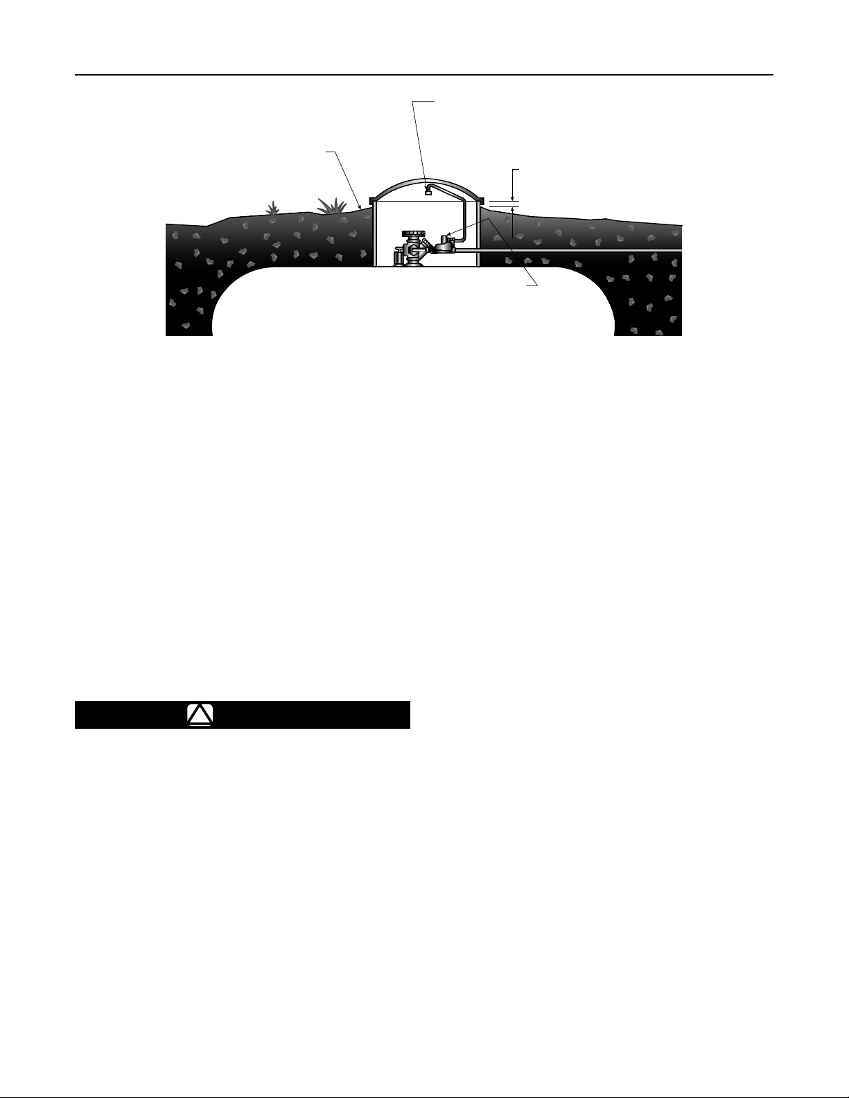
Regulators installed in the dome of an underground
container require a vent tube to prevent water from entering
the regulator spring case, see Figure 5.
Note
Types R632A and R632E integral regulators
installed on underground tanks require the
use of 2 vent tubes, one for the first stage
vent (1/4 in. OD copper tube inverted flare
connection: 7/16-24 UN thread) and the other
for the second stage vent (3/4 in. NPT) of
the regulator.
Remove the vent screens and install vent tubes. The vent
tube must be run from the regulator vent to above the
maximum water table. The vent tube opening must terminate
at the extreme top inside of the dome cover. Make sure the
regulator’s closing cap is on tightly, and maintain drainage
away from the dome at all times.
Outdoor Installations with Underground
Vent Lines
When installed per code, the underground vent line must not
restrict the gas flow from the regulator’s internal relief valve
and must remain clear of debris, dry and fully open at all
times. Joints in the vent line must be fully sealed to prevent
moisture intrusion into the vent line. A vent assembly, such
as the Fisher Y602 Series, should be used on the end of
the vent line to prevent entry of precipitation, water or other
debris. When underground vent lines are used in humid
environments, the vent line must be designed to allow for
proper drainage of any collected moisture or condensation.
Adjustment
Each regulator is factory set. If it becomes necessary to
increase the outlet pressure, remove the closing cap and
turn the adjustment screw clockwise. Turn the adjusting
screw counterclockwise to decrease the outlet pressure. The
first stage portion of the Types R632A and R632E integral
regulators is non-adjustable.
WATER MARK LEFT IN HOUSING DOME AT LEVEL ABOVE REGULATOR VENT OR END OF
VENT TUBE REQUIRES REPLACEMENT OF REGULATOR. INSTALL REGULATOR PROPERLY.
Figure 5. Underground Installation
GRADE GROUND DOWNWARD AND
SLOPING AWAY FROM HOUSING DOME.
THIS PREVENTS WATER COLLECTING
AND RUNNING INTO OR STANDING
AROUND HOUSING DOME.
END OF REGULATOR VENT
TUBE LOCATED AT TOP INSIDE
OF HOUSING DOME COVER
2 in. / 5.1 cm
MINIMUM
REGULATOR ADJUSTMENT
CLOSURE CAP MUST BE TIGHT.
T14448-A2
Loading ...
Loading ...