Loading ...
Loading ...
Loading ...

R600 and HSRL Series LP-Gas Regulators
4
Installation Location
• The installed regulator should be adequately protected from
vehicular traffic and damage from other external sources.
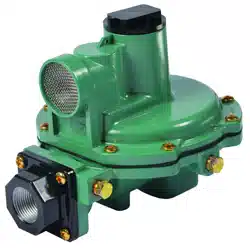
• Install the regulator with the vent pointed vertically down,
see Figure 2. If the vent cannot be installed in a vertically
down position, the regulator must be installed under a
separate protective cover. Installing the regulator with the
vent down allows condensation to drain, minimizes the
entry of water or other debris from entering the vent and
minimizes vent blockage from freezing precipitation.
REGULATOR
APPLICATION
TYPE
NUMBER
CAPACITY
BTU/HR
PROPANE
(1)
INLET
CONNECTION
OUTLET
CONNECTION
OUTLET
PRESSURE
SETTING
3/4 IN. NPT
SCREENED
VENT STANDARD
LOCATION
Second Stage
R622-BCF 875,000 1/2 in. FNPT 1/2 in. FNPT
11 in. w.c. /
27 mbar
Over Inlet
R642-DFF 900,000
3/4 in. FNPT
3/4 in. FNPT
R652-DFF 1,000,000
R622-CFF
1,400,000
1/2 in. FNPT
R622-DFF 3/4 in. FNPT
R622-CFGXA 1,125,000 1/2 in. FNPT
3/4 in. FNPT
18 in. w.c. /
45 mbar
HSRL-BFC
(2)
2,100,000
3/4 in. FNPT
11 in. w.c. /
27 mbar
HSRL-CFC
(2)
1 in. FNPT 1 in. FNPT
Integral
Two-Stage
R632A-BCF
850,000
1/4 in. FNPT
1/2 in. FNPT
11 in. w.c. /
27 mbar
First Stage
(3)
:
Down
Second Stage:
Over Outlet
R632A-HCF FPOL
R632A-CFF 950,000 1/4 in. FNPT
3/4 in. FNPT
R632A-JFF 850,000 FPOL
R632A-BCFXA
850,000
1/4 in. FNPT
1/2 in. FNPT
11 in. w.c /
27 mbar
First Stage
(3)
:
Opposite gauge taps
Second Stage:
Opposite gauge taps
R632A-HCFXA FPOL
R632A-CFFXA 950,000 1/4 in. FNPT
3/4 in. FNPT
R632A-JFFXA 850,000 FPOL
Integral
2 psig / 0.14 bar
Service
R632E-BCH 850,000 1/4 in. FNPT
1/2 in. FNPT
2 psig / 0.14 bar
First Stage
(3)
:
Down
Second Stage:
Over Outlet
R632E-HCH 900,000 FPOL
R632E-CFH
850,000
1/4 in. FNPT
3/4 in. FNPT
R632E-JFH FPOL
2 psig / 0.14 bar
Service
R622E-BCH 1,250,000 1/2 in. FNPT 1/2 in. FNPT
2 psig / 0.14 bar Over InletR622E-DCH 1,500,000
3/4 in. FNPT 3/4 in. FNPT
R652E-DFH 1,400,000
First Stage
R622H-BGK 2,000,000
1/2 in. FNPT
1/2 in. FNPT
5 psig / 0.35 bar
Over Outlet
R622H-BGJ
2,100,000 10 psig / 0.69 barR622H-HGJ
FPOL
R622H-HGJKA
R622H-JGK
2,250,000
3/4 in. FNPT
5 psig / 0.35 bar
R622H-JGJ
10 psig / 0.69 bar
R622H-DGJ 2,400,000 3/4 in. FNPT
1. Capacities Based on:
Second Stage: 10 psig / 0.69 bar inlet pressure and 2 in. w.c. / 5 mbar droop.
Integral Two-stage: 30 psig / 2.1 bar and 2 in. w.c. / 5 mbar droop.
Integral Two psig Service: 30 psig / 2.1 bar and 20% droop.
2 psig / 0.14 bar Service: 10 psig / 0.69 bar inlet pressure and 20% droop.
First Stage: 30 psig / 2.1 bar inlet pressure and 20% droop.
2. Straight globe valve body conguration.
3. Integral First Stage Vent size: 7/16-24 UN thread for 1/4 in. OD copper tube inverted are tting.
Table 2. Capacity, Connection Sizes and Vent Orientation
• Do not install the regulator in a location where there can
be excessive water accumulation or ice formation, such
as directly beneath a down spout, gutter or roof line of
building. Even a protective hood may not provide adequate
protection in these instances.
• Install the regulator so that any gas discharge through the
vent or vent assembly is over 3 ft / 0.91 m horizontally from
any building opening below the level of discharge.
• Install the regulator high enough above ground level at
least 18 in. / 45 cm - so that rain splatter cannot freeze
in the vent.
Loading ...
Loading ...
Loading ...