Loading ...
Loading ...
R600 and HSRL Series LP-Gas Regulators
3
TYPE
TYPICAL SETPOINT
NOMINAL RELIEF VALVE
START-TO-DISCHARGE
MAXIMUM INLET PRESSURE TO NOT EXCEED
OUTLET PRESSURE WITH DISC REMOVED
Inlet Pressure Maximum Outlet Pressure
psig bar psig bar psig bar psig bar
HSRL
11 in. w.c. 27 mbar 1 69 mbar
15 1.0
2 0.14
R622 and R642
50 3.4
R652
R632A
(1)
250 17.2
R632E
(1)
2 0.14 3.5 0.24
250 17.2
5 0.34R622E
50 3.4
R652E
R622H 10 0.69 20 1.37 Not Applicable
1. For integral two-stage regulators, the second stage disc is removed.
Table 1. Relief Valve Specifications
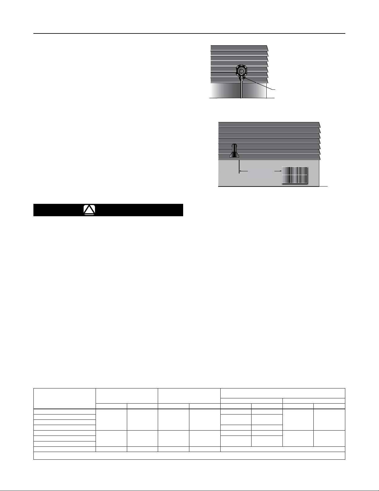
Figure 2. Regulator with Vent Pointed Down
3
3 FT /
0.91 m
VENT POINTED DOWN
Integral Two-stage Regulator
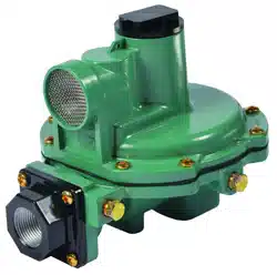
The Type R632A integral two-stage regulator contains a
non-adjustable first stage regulator on the inlet. The second
stage provides 11 in. w.c. / 27 mbar outlet pressure. The
second stage portion has a high capacity internal relief valve
construction. The first stage does not have an internal relief
valve. The regulators are normally painted GRAY with a
BLACK CAP.
Integral Two psig Service Regulator
The Type R632E integral two psig service regulator contains
a non-adjustable first stage regulator on the inlet. The
second stage provides 2 psig / 0.14 bar outlet pressure. The
second stage portion has a high capacity internal relief valve
construction. The first stage does not have an internal relief
valve. The regulators are normally painted GRAY with a
WHITE CAP and White 2-psig STICKER.
Installation
!
WARNING
All vents should be kept open to permit free
flow of air in and out of the regulator. Protect
vent openings against the entrance of rain,
snow, ice formation, paint, mud, insects,
water from an irrigation system or any other
foreign material that could plug the vent or
vent line or accumulate in the vent line.
LP-Gas may discharge to the atmosphere
through the vent. An obstructed vent which
limits air or gas flow can cause abnormally
high pressure that could result in personal
injury or property damage. Failure to use a
vent line on Indoor Installations can cause a
hazardous accumulation of gas which could
result in personal injury or property damage.
Types R622H, R622E, R632A, R632E and
R652E regulators are not suitable for
indoor installations.
Never use a Type R622H, R622E, R632E or
R652E (pounds-to-pounds) regulator on low
pressure (inches of water column) service
because personal injury or property damage
could occur. The Types R622E and R652E are
not suitable for use as a “first stage” regulator.
General Installation Instructions
Before installing the regulator,
• Check for damage, which might have occurred
in shipment.
• Check for and remove any dirt or foreign material, which
may have accumulated in the regulator body.
• Replace old pigtails. Blow out any debris, dirt or copper
sulfate in the copper tubing and the pipeline.
• Apply pipe compound to the male threads of the pipe
before installing the regulator.
• Make sure gas flow through the regulator is in the same
direction as the arrow on the body. “Inlet” and “Outlet”
connections are clearly marked.
T14446-A2
Loading ...
Loading ...
Loading ...