User manual Dryer
SAFETY INSTRUCTIONS
Installing your dryer
Unpacking your dryer

- Top cover
- Control panel
- Door
- Filter
- Water Inlet (Steam model only)
- Duct Exhaust
Accessories (Steam model only)

Basic requirements
Make sure you have everything necessary for the proper installation
• A GROUNDED ELECTRICAL OUTLET is required.
• A POWER CORD electric dryer (except for Canada).
• GAS LINES (if a gas dryer) must meet national and local codes.
• The EXHAUST SYSTEM must be made of rigid metal or flexible stiff-walled metal exhaust ducting.
Grounding
This dryer must be grounded. In the event of a malfunction or breakdown, grounding the product will reduce the risk of electrical shock by providing a path of least resistance for the electrical current.
Gas models
Your dryer has a cord with an equipment-grounding conductor and a grounding plug.
- The plug must be plugged into an appropriate outlet that is properly installed and grounded in accordance with all local codes and ordinances.
- Do not modify the plug provided with your dryer – if it doesn’t fit the outlet, have a proper outlet installed by a qualified electrician.
- Never connect the ground wire to the plastic plumbing lines, gas lines, or hot water pipes.
Electric models
Your dryer has an optional cord with an equipment-grounding conductor and a grounding plug, which is sold separately.
- The plug must be plugged into an appropriate outlet that is properly installed and grounded in accordance with all local codes and ordinances.
- Do not modify the plug provided with your dryer – if it doesn’t fit the outlet, have a proper outlet installed by a qualified electrician.
- If a power cord is not used and the electric dryer is to be permanently wired, the dryer must be connected to a permanently grounded metal wiring system, or an equipment grounding conductor must be run with the circuit conductors and connected to the equipment grounding terminal or lead on the dryer.
Alcove or closet installations
 WARNING
- The dryer must be exhausted to the outside to reduce the risk of fire when installed in an alcove or closet.
- No other fuel-burning appliance should be installed in the same closet as the dryer
Minimum clearances between the dryer and adjacent walls or other surfaces:


Undercounter installation

- A 39 in. (991 mm)
- B 1 in. (25 mm)
- C 27 in. (686 mm)
- D 1 in. (25 mm)
Installation with pedestal

- A 38.7 in. (984 mm)
- B 53.3 in. (1355 mm)
- C 27 in. (686 mm)
- D 53 in. (1345 mm) to clear open door
- E 32.4 in. (823 mm) F 5 in. (127 mm)
Installation with stacked washing machine and dryer

A 3 in. (76 mm)
B 48 in.² (3100 mm²
C 24 in.² (1550 mm²)
D 3 in. (76 mm)
E 6 in. (152 mm) *
F 77.5 in. (1968 mm)
G 1 in. (25 mm)
H 27 in. (686 mm)
I 5 in. (127 mm)
J 1 in. (25 mm)
K 32.4 in. (823 mm)
L 8 in. (203 mm)
 The front of the closet must have two unobstructed air openings (B, C) for a combined minimum total area of 72 in² (465 cm²) with a minimum clearance of 3 in. (7.6 cm) at the top (A) and bottom (D). External exhaust elbow requires additional space (L).
 Stacking (MODEL NO: SKK-7A) Samsung’s Washer and Dryer can be stacked to maximize usable space. You can purchase an optional stacking kit from your Samsung retailer. For details about stacking and compatible models, refer to the user manual included in the stacking kit you purchase.
Ducting requirements

 * Do not use non-metallic flexible ducts.
• Use a 4 inch (10.2 cm) diameter rigid aluminum or rigid galvanized steel duct.
• Do not use a smaller duct.
• Ducts larger than 4 inches (10.2 cm) in diameter can result in increased accumulation of lint.
• Lint should be removed regularly.
• If a flexible metal duct must be used, use the type with a stiff sheet metal wall. Do not use a flexible duct with a thin foil wall. A serious blockage can result if the flexible metal duct is bent too sharply.
• Never install any type of flexible duct in walls, ceilings, or other concealed spaces.
• Keep the exhaust duct as straight and short as possible.
• Secure joints with duct tape. Do not use screws.
• Plastic flexible ducts can kink, sag, be punctured, reduce airflow, extend drying times, and affect the dryer operation.
• Exhaust systems longer than recommended can extend drying times, affect machine operations, and collect lint
• The exhaust duct should end with an exhaust hood with a swing-out damper to prevent back drafts and entry of wildlife. Never use an exhaust hood with a magnetic damper.
• The hood should have at least 12 inches (30.5 cm) of clearance between the bottom of the hood and the ground or other obstruction. The hood opening should point down.
• Never install a screen over the exhaust outlet.
• To avoid lint buildup, do not exhaust the dryer directly into a window well. Do not exhaust under a house or porch.
• If the exhaust duct must run through an unheated area, the duct should be insulated and slope slightly down towards the exhaust hood to reduce condensation and lint buildup.
• Inspect and clean the interior of the exhaust system at least once a year. Unplug the power cord before cleaning.
• Check frequently to make sure the exhaust hood damper opens and closes freely.
• Check once per month, and clean at least once per year.
Note: If your clothes are not getting dry, then check the duct for obstructions.
• Do not exhaust the dryer into a wall, ceiling, crawl space, or concealed space of a building, gas vent, or any other common duct or chimney. This could create a fire hazard from the lint expelled by the dryer.
Exhausting
The dryer shall not be exhausted into a chimney, a wall, a ceiling, an attic, a crawl space, or a concealed space of a building.
Exhausting the dryer to the outside will prevent large amounts of lint and moisture from being blown into the room.
- All dryers must be exhausted to the outside.
- Do not assemble the duct with screws or other fastening means that extend into the duct and catch lint.
- The exhaust duct should be 4 inches (102 mm) in diameter.
- The total length of flexible metal duct shall not exceed 2.4 m (7.8 ft.).
Dryer exhaust tips
WARNING: A plastic or non-metal flexible duct presents a potential fire hazard.
• Make sure your dryer is installed properly so it exhausts air easily.
• Use a 4” diameter rigid metal duct. Tape all joints, including at the dryer. Never use lint-trapping screws
• Keep ducts as straight as possible.
• Clean all old ducts before installing your new dryer.
• Be sure the vent flap opens and closes freely.
• Inspect and clean the exhaust system annually.

Don’t let a poor exhaust system slow the drying process by:
- Restricting your dryer with a poor exhaust system.

- Using a plastic, thin foil, or non-metal flexible duct.

- Unnecessarily using long ducts that have many elbows.

- Allowing dented or clogged ducts and vent.

Gas requirements
THE INSTALLATION MUST CONFORM WITH LOCAL CODES, OR IN THE ABSENCE OF LOCAL CODES, WITH THE NATIONAL FUEL GAS CODE ANSI/Z223.1, LATEST REVISION (FOR THE UNITED STATES), OR WITH THE CAN/CGA-B149 INSTALLATION CODES (FOR CANADA).
• Use only natural or LP (liquid propane) gases.
• This dryer designed for use with natural gas. If you plan to use your dryer with LP gas (liquid propane), the conversion must be done by a qualified service technician in order to achieve safe and proper performance. (LNG models only)
• A 1/2 inch (1.27 cm) gas supply line is recommended and must be reduced to connect to the 3/8 inch (1 cm) gas line on your dryer. The National Fuel Gas Code requires that an accessible, approved manual gas shut-off valve be installed within 6 inches of your dryer.
• Gas dryers installed in residential garages must be raised 18 inches (46 cm) above the floor.
• Additionally, a 1/8 inch (0.3 cm) N.P.T. (National Pipe Thread) plugged tapping, accessible for test gauge connection, must be installed immediately upstream of your dryer’s gas supply connection.
• Your dryer must be disconnected from the gas supply pipe system during any pressure testing of the system.
• DO NOT reuse old flexible metal gas lines. Flexible gas lines must be design certified by the American Gas Association (CGA in Canada).
• Any pipe joint compound used must be resistant to the action of any liquefied petroleum gas.
• As a courtesy, most local gas utilities will inspect a gas appliance installation.
• GAS IGNITION - Your dryer uses an automatic ignition system to ignite the burner. There is no constant burning pilot.
Commonwealth of massachusetts installation instructions
WARNING
- Gas leaks may occur in your system, creating a dangerous situation.
- Gas leaks may not be detected by smell alone.
- Gas suppliers recommend that you purchase and install a UL-approved gas detector.
- Install and use it in accordance with the manufacturer’s instructions.
Exhaust ducting guide
Ducting
- Make sure the dryer is installed properly so the air exhausts freely.
- Use 4-inch rigid metal ducts. Tape all joints including the dryer connection. Never use lint-trapping screws.
- To facilitate the exhaust, keep the ducts as straight as possible.
Cleaning
Clean all old ducts before installing the dryer, and make sure the vent flap opens and closes freely. We recommend that you clean the exhaust system annually or on a regular basis.
WARNING
- To prevent fire, do not use plastic, thin-foil, or non-metal flexible ducts of any kind.
- Do not use a poor exhaust system because it slows down the dryer’s performance
- Do not use excessively long ducts that have multiple elbows.
- Do not use crushed or clogged venting or ducts.
Electrical requirements
Electrical connections
Before operating or testing, follow all grounding instructions in the “Grounding” section on page 9. An individual branch (or separate) circuit serving only your dryer is recommended. DO NOT USE AN EXTENSION CORD.
Gas models – U.S. and Canada
A 120 volt, 60 Hz AC approved electrical service, with a 15-ampere fuse or circuit breaker is required.
Electric models – U.S. only
Most U.S. dryers require a 120/240 volt, 60 Hz AC approved electrical service. Some require 120/208 volt, 60 Hz approved electrical service. The electric service requirements can be found on the data label located behind the door. A 30-ampere fuse or circuit breaker on both sides of the line is required.
If a power cord is used, the cord should be plugged into a 30-ampere receptacle.
The power cord is NOT provided with U.S. electric model dryers.
3-WIRE system connections
- Loosen or remove the center terminal block screw.
- Connect the neutral wire (white or center wire) of the power cord to the center, silver-colored terminal screw of the terminal block. Tighten the screw
- Connect the other wires to the outer terminal block screws. Tighten the screws.
- Tighten the strain relief screws.
- Insert the tab of the terminal block cover into your dryer’s rear panel slot.
- Secure the cover with a hold-down screw.


If converting from a 4-wire electrical system to a 3-wire, the ground strap must be reconnected to the terminal block support to ground the dryer frame to the neutral conductor.
4-WIRE system connections
- Remove the center terminal block screw.
- Connect the ground wire (green or unwrapped) of the power cord to the external ground conductor screw.
- Connect the neutral wire (white or center wire) of the power cord and the appliance ground wire (white or green/yellow stripes) under the central screw of the terminal block.
- Connect the other wires to the outer terminal block screws. Tighten the screws.
- Tighten the strain relief screws.
- Insert the tab of the terminal block cover into your dryer’s rear panel slot.
- Secure the cover with a hold-down screw.


8. With a level, check your dryer and make the necessary adjustments to the leveling legs.
9. At this time, make sure all gas connections (on gas models), exhaust and electrical connections are complete. Plug in your dryer, and check its operation by using the checklist below.
10. (GAS MODELS ONLY)
The burner may not ignite initially due to air in the gas line. Allowing your dryer to operate on a heat setting will purge the line. If the gas does not ignite within 5 minutes, turn your dryer off and wait 5 minutes. Be sure the gas supply to your dryer has been turned on. In order to confirm the gas ignition, check the exhaust for heat.
Connecting the inlet hose (Steam model only)
The dryer must be connected to the cold water faucet using the new inlet hoses. Do not use old hoses.
1. Turn the cold water faucet off.
2. Attach the brass female end of the Y connector (A) to the cold water faucet.
3. Attach the straight end of long hose (B) to the Y connector.
4. Using pliers, tighten the coupling with an additional two-thirds turn

If the Y connector cannot be attached directly to the cold water faucet, the short hose must be used. (If space permits, please skip steps 5 to 8, and go directly to step 9.)
5. Attach the short inlet hose (C) to the cold water faucet. Screw on the coupling by hand until it is seated on the faucet.
6. Using the pliers, tighten the coupling with an additional two-thirds turn.
7. Attach the Y connector (A) to the brass male end of the small hose. Screw on the coupling by hand until it is seated on the connector.
8. Using the pliers, tighten the coupling with an additional two-thirds turn. C A
9. Attach the angled end of long hoses to the fill valve at the bottom of the dryer rear frame. Screw on the coupling by hand until it is seated on the fill valve connector.
10. Using pliers, tighten the coupling with an additional two-thirds turn.


11. Attach the washer hose (D) to the other side of the Y connector (A). Screw on the hose coupling until it is tight. Using pliers, tighten the coupling with an additional two thirds turn.
12. Check that the water faucets are on.
13. Check for leaks around the Y connector, faucets and hoses.
Installation
For the proper installation, we recommend that you hire a qualified installer.
1. Move your dryer to an appropriate location for the installation. Consider installing the dryer and washer side-by-side, to allow access to the gas, electrical, and exhaust connections. Place two of the carton cushion-tops on the floor. Tip your dryer on its side so it lies across both cushion-tops.
2. Set your dryer back in an upright position.
3. To ensure that the dryer provides the optimal drying performance, it must be level. To minimize vibrations, noise, and unwanted movement, the floor must be a perfectly level, solid surface. To set the dryer to the same height as the washer, fully retract the leveling feet (A) by turning them counterclockwise, then loosen the legs by turning them clockwise.
Adjust the leveling feet only as much as necessary to level the dryer. Extending the leveling feet more than necessary can cause the dryer to vibrate.

4. Review the “Exhausting” section on page 13 before installing the exhaust system. Install the ductwork from your dryer to the exhaust hood. The crimped end of the duct sections must point away from your dryer.
• DO NOT use sheet metal screws when assembling the ducting. These joints should be taped.
• Never use plastic flexible exhaust material.
• Tip for tight installations: install a section of the exhaust system onto your dryer before putting it in place.
• Use duct tape to secure this section to your dryer, but do not cover the ventilation slots at the back of the unit in dryer cabinet.
5. Review the “Electrical requirements” section on page 16.
BEFORE OPERATING OR TESTING, follow the grounding instructions in the “Grounding” section on page 9.
WARNING - U.S. MODELS RISK OF ELECTRIC SHOCK - All U.S. models are produced for a 3-WIRE SYSTEM CONNECTION. The dryer frame is grounded to the neutral conductor at the terminal block.
A 4-WIRE SYSTEM CONNECTION is required for new or remodeled construction, mobile homes, or if local codes do not permit grounding through the neutral conductor. If the 4-wire system is used, the dryer frame cannot be grounded to the neutral conductor at the terminal block. Refer to the following instructions for “Electrical connections” on page 17.
Remove the terminal block cover plate.
Insert the power cord with a UL-listed strain relief through the hole provided in the cabinet near the terminal block.
A strain relief must be used.
Do not loosen the nuts already installed on the terminal block. Be sure they are tight. Use a 3/8 in. (1 cm) deep well socket.
6. Review the “Gas requirements” section on page 15.
Remove the pipe thread protective cap. Apply a pipe joint compound or about 1½ wraps of Teflon tape over all threaded connections.
The pipe joint compound must be resistant to the actions of any liquefied petroleum gas.
Connect the gas supply to your dryer. An additional fitting is required to connect the 3/4” (1.9 cm) female thread end of a flexible connector to the 3/8” (1 cm) male threaded end on the dryer. Securely tighten the gas line fitting over the threads.
Turn on the gas supply. Check all gas connections for leaks using a soap solution. If bubbles appear, tighten the connections and recheck.
DO NOT use an open flame to check for gas leaks.
Door reversal
Type 1
1. Unplug the power cord.
2. Remove two door hinge screws.
3. Lift the door and remove it.

4. Remove two screws from the frame front.

5. Remove the two screws from the opposite side of the door hinge.

6. Remove the two screws from the holder lever.

7. Reassemble the two screws on the inside holes.

8. Remove a screw from the door hinge. The screw is for pre-fixing the door to the frame front.

9. Reassemble the screw in the other hole.

10. Place the door on the other side and reattach it to the dryer.

11. Reattach the holder lever.

12. Reattach the screws in the remaining holes.

Type 2
1. Unplug the power cord.
2. Remove two door hinge screws.
3. Lift the door and remove it.

4. Remove two screws from the frame front

5. Remove the two screws from the opposite side of the door hinge.

6. While holding down the upper hook (A) using the flat-head screwdriver in your right hand, pull out the upper area of the holder lever with your left hand to remove.

7. Reassemble the two screws on the inside holes.

8. Remove a screw from the door hinge. The screw is for pre-fixing the door to the frame front.

9. Reassemble the screw in the other hole.

10. Place the door on the other side and reattach it to the dryer.

11. Fit the lower area of the holder lever in the frame-front hole in the arrow direction, and push in the holder lever to the end while holding down the hook (A). A

12. Reattach the screws in the remaining holes.

13. When the holder lever is attached properly, it is supposed to be flexible in all four directions.

Final installation checklist
- The dryer is plugged into an electrical outlet and is properly grounded.
- The exhaust ductwork is hooked up and the joints are taped.
- A plastic flexible duct is NOT used.
- Use rigid or stiff-walled flexible metal vent material.
- The dryer is level and is sitting firmly on the floor.
- Gas models – the gas is turned on with no gas leaks.
- Start your dryer to confirm that it runs, heats, and shuts off.
Operating instructions, tips
Overview of the control panel
The courses and functions differ depending on the model. Please check your model before proceeding.
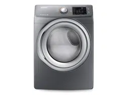
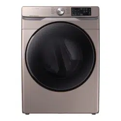
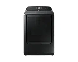
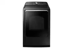
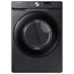
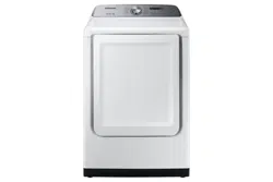
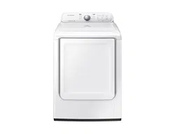
DV42H5400*

DV42H5200*

DV42H5000*

1. Cycle selector
To select a cycle, rotate the Cycle selector dial to the desired cycle.
The indicator light by the cycle name will illuminate. The ECO NORMAL, NORMAL, HEAVY DUTY, BEDDING, SANITIZE, PERM PRESS, WOOL and DELICATES cycles are Sensor Dry cycles. Sensor Dry automatically senses the moisture in the load and shuts the dryer off when the selected dryness level (Very Dry to Damp Dry) is reached.
CYCLE, RECOMMENDED & ITEMS DETAILS
1. NORMAL
- Cottons, Work clothes, Linen, Mixed loads => Use this cycle to dry loads such as cotton, underwear, and linen.
2. HEAVY DUTY
- Heavy fabrics such as jean, Corduroys, Heavy work clothes => Use this cycle to get high heat for heavy fabrics such as jeans, corduroys, or work clothes.
3. BEDDING
- Bulky items such as blankets, Sheets, Comforters, Pillows => For bulky items such as blankets, sheets, and comforters.
4. SANITIZE
- Bedding, Curtains, Children’s clothing Sanitize garments by infusing high temperature heat deep into the fabric during the drying cycle. => Use this course to keep your bedding and curtains clean through sanitization.
5. PERM PRESS
- Shirts, Synthetic fabrics, Knits, Wrinkle-free cottons, Permanent => Dry wrinkle-free cottons, synthetic fabrics, knits, and permanent press fabrics automatically
6. WOOL
- For machine washable and tumble dryable wool only (Maximum amount : 3lb) => For machine washable and tumble dryable wool only
7. DELICATES
- Underwear, Blouses, Lingerie => The DELICATES cycle is designed to dry heat-sensitive items at a low drying temperature.
8. ACTIVE WEAR
- Water-repellent wear, performance clothes, Sports wear (Maximum amount : 4lb) => The ACTIVE WEAR cycle is for exercise wear and outdoor wear such as sports jerseys, training pants, water-repellent jackets and other performance clothing. Thick fabrics like a zipper or velcro closure of a jacket, or training socks may not be completely dried.
9. QUICK DRY
- Small loads => Provides a 30 minutes drying cycle.
10. TIME DRY
- Any load => The TIME DRY allows you to select a cycle time in minutes. Turn the Cycle Selector dial to TIME DRY, then press the Adjust Time up arrow to set the drying time. Press the arrow repeatedly to scroll through the time settings.
11. AIR FLUFF
- Foam, Rubber, Plastic => The AIR FLUFF cycle tumbles the load in room temperature air.
12. WRINKLE RELEASE
- Shirts, Trouser, Blouses => The WRINKLE RELEASE cycle will release wrinkles from items that are clean, dry, and only slightly wrinkled, such as clothes from a crowded closet, suitcase or items that have been in the dryer too long after the cycle has ended. Wrinkle Release can be used with any temperature selection.
13. REFRESH
- Shirts, Trouser, Comforter, Pillows (Confirm that the laundry load is dry) => This cycle is best for smoothing out wrinkles and reducing odors from loads consisting of one to four dry items. In this cycle a small amount of water is sprayed into the dryer drum after several minutes of tumbling with heat
14. WRINKLE AWAY
- Shirts, Trouser, Blouses (Confirm that the laundry load is dry) => The WRINKLE AWAY cycle removes wrinkles from clothes stored in closets, etc. It provides wrinkle release via optimized steam care. For best results, load 2-3 items at once. You can extend the drying time by a minimum of 20 minutes, depending on the item type or load.
2. Cycle options
1. Anti Static (Steam Model Only)
- To reduce statics by clothing friction and spray steam at the later period of drying cycle.
- It is only available with: NORMAL, HEAVY DUTY, PERM PRESS, DELICATES (Dry level of every course exceeds Normal) and TIME DRY course. In order to reduce statics, the drum can be paused during operation.
2. Rack Dry
- Rack Dry is available in the TIME DRY cycle. Temperature will be set to Extra Low only. (Refer to the “Rack dry (DV42H5400* Only)” section on page 31.)
3. Mixed Load Bell
- The mixed load bell that notifies you when the average dry level in a load is damp dry (80 % dried). This lets you take garments that you don’t want fully dried or that dry quickly out of the dryer early while letting others continue to dry. You can select this function in all Sensor Dry cycles except WOOL, SANITIZE. The dry level selections are limited to Normal Dry, More Dry, and Very Dry.
4. Wrinkle Prevent
- Wrinkle Prevent provides approximately 180 minutes of intermittent tumbling in unheated air at the end of the cycle to reduce wrinkling. Press the Wrinkle Prevent button to activate this feature. The indicator light above the pad will illuminate when Wrinkle Prevent is selected. The load is dry, and can be removed at any time during the Wrinkle Prevent cycle.
5. My Cycle
- Choose your favorite cycle including cycle, temp, dry level option, etc. (Refer to the “My Cycle” section on page 33.)
6. Adjust Time
- Time can be added or subtracted from the automatically set times in the Manual Dry cycles (TIME DRY, QUICK DRY, or AIR FLUFF cycles) and WRINKLE AWAY cycle. To add or subtract time from the cycle, press the Adjust Time arrow pad up or down until the desired time is displayed.
7. Small Load Care™
- To control operation rate for drying a small loads at Sensor Dry course. It is only available with: NORMAL, HEAVY DUTY, PERM PRESS and DELICATES course. It can’t be selected/cancelled when the drying course is running. In order to improve drying effect and control operation rate, the drum can be paused during operation.
3. Dry Level
To select the dry level in the NORMAL, HEAVY DUTY, or other Sensor Dry cycles, press the Dry Level button. An indicator light will illuminate next to the desired dryness level.
Press the button repeatedly to scroll through the settings. Larger or bulkier loads may require the Very Dry or More Dry setting for complete dryness.
The Less Dry setting is best suited for lightweight fabrics or for leaving some moisture in the clothing at the end of the cycle. Damp Dry is designed to partially dry items. Use for items that lay flat or hang to dry.
4. Temp.
To select the correct temperature for the load, press the Temp. button. An indicator light will illuminate next to the desired temperature. Press the button repeatedly to scroll through the settings.

5. Time
When using Manual Dry cycles, you can adjust the drying time by pressing the Time selection button. During the Sensor Dry cycle, the time light indicator is off because exact drying times are determined by fluctuating humidity levels.
6. LED Display
Display The display window shows the estimated time remaining in the cycle after the Start/Pause button is pressed. The estimated time remaining may fluctuate as the cycle progresses.
The Drying light will illuminate and remain lit until the cycle is complete. When your dryer is in the cool-down phase, the Cooling light will illuminate.
When your dryer is in the wrinkle prevent phase, the Wrinkle Prevent light will illuminate. When the cycle is complete, “End” will appear in the display panel until the dryer door is opened or the Power button is pushed. If your dryer is paused during a cycle, the indicator lights will blink until the Start/Pause button is pressed.
7. Power
Press once to turn your dryer on.
Press again to turn it off. If your dryer is left on for more than 10 minutes without any buttons being touched, the power automatically turns off.
8. Start/Pause
Press to pause and restart programs.
9. Indicators

Load the dryer properly
Getting started
- Load your dryer loosely (DO NOT overload).
- Close the door.
- Select the appropriate cycle and options for the load. (For detail, refer to the “Cycle overview” on next page.)
- Press the Start/Pause button.
- The dryer indicator light will illuminate.
- The estimated cycle time will appear in the display. The time may fluctuate as humidity levels fluctuate in the dryer.
- When the cycle is complete, “End” will appear in the display.
- Pressing Power cancels the cycle and stops your dryer.
- The Drying, Cooling, and Wrinkle Prevent indicator lights will illuminate during those portions of the cycle.
Do not place anything on top of your dryer while it is running
Cycle overview
Predefined

Load size recommendations
For best results, follow the load size recommendations for each drying cycle

Options

Rack dry (DV42H5400* Only)
Installing the drying rack
- Open the dryer door.
- Position the drying rack in the tumbler, placing the front lip of the drying rack (A) on the top of the lint filter
- Place the rear legs in the two recessed areas of the dryer’s back wall, and then push down the middle of the drying rack to fix in place
- Place the items to be dried on the rack, leaving space between them so air can circulate.
- Close the dryer door.
- Press the Rack Dry button in the TIME DRY cycle and then select the time according to the amount of moisture and the weight of the items. The drying rack can be also used at AIR FLUFF cycle.


Drying foam rubber, plastic, or rubber on a heat setting may cause damage to the items and lead to a fire hazard.
The drying rack is not included in the DV42H5200* and DV42H5000* models. You can purchase the drying rack (part code: DC61-02705A) at a local Samsung service center.
Child Lock
Prevents children from playing with your dryer.
Setting/Releasing
To turn Child Lock on or off, press both the Temp. and Time buttons simultaneously for 3 seconds.
Child Lock Details
- You can turn Child Lock on while your dryer is running.
- Once you set the Child Lock function, no button, except for the Power button, will respond until you turn off the Child Lock function.
- The “Child Lock ”
 indicator will be lit.
- If the dryer is powered on again, the Child Lock function stays on.
- To turn off Child Lock, follow the instructions above. When other buttons, except for the Power button, do not respond, check the Child Lock indicator. If Child Lock is on, follow the instructions above to turn Child Lock of
Drum Light
Lights the dryer drum while the dryer is running
Turning On and Off
To turn on or turn off the Drum Light, press and hold the Wrinkle Prevent (DV42H5400*) / Small Load Care™ (DV42H5200*) button for 3 seconds; press the Drum Light (DV42H5000*) button.
You can turn the Drum Light on and off while your dryer is running and when it is stopped.
If you do not turn the Drum Light off 5 minutes after turning it on, the Drum Light is automatically turned off.
Sound Off
Use this function to mute the button and operating sounds
Setting and Releasing
To turn the Sound Off function on or off, press and hold the Dry Level button for 3 seconds (DV42H5400*); press the Sound button (DV42H5200*, DV42H5000*).
Sound Off Details:
1. You can set Sound Off while your dryer is running.
2. Once you have activated Sound Off, the button and operating sounds are muted until you deactivate it.
3. The “Sound Off  ” indicator will be lit.
If you do not turn the Sound Off function off before you turn your dryer off, It will still be on when you turn your dryer on again. To turn Sound Off off, follow the instructions above.
My Cycle
Load
• Press the My Cycle button for less than 3 seconds to activate My Cycle mode where all course settings and selected options are loaded.
• The My Cycle indicator turns on when the mode is active.
• If you have not configured any My Cycle settings, the default course settings are loaded.
Save
You can add and save preferred options to My Cycle.
1. Turn the course dial to select a course.
2. Set necessary options for the selected course. For details on each course and options, see page 30.
3. Press and hold the My Cycle button for more than 3 seconds to save the course options. The My Cycle indicator blinks while the options are being saved.
The Wrinkle Prevent option is not available for the My Cycle function.
Smart Care
This function enables you to check the status of the dryer using a smartphone.
1. Press and hold the Small Load Care™ (DV42H5400*) or Sound (DV42H5200*, DV42H5000*) button for 3 seconds when an error occurs or if you haven’t pressed any buttons on the dryer after you turned the power on.
2. When the Smart Care function is activated, the LED on the window display rotates for 2 or 3 seconds and then the error code will appear in the display panel.
3. Run the Smart Care app on your smart phone.
The Smart Care function has been optimized for: Galaxy & iPhone series (cannot be supported for some models).
4. If the smart phone’s camera is focused on the display panel of the dryer, the panel and error message is automatically recognized and the error type and countermeasures are displayed on the smart phone.
5. If the smartphone fails to recognize the error code more than twice, please enter the error code displayed on the display panel of the dryer manually into the Smart Care app
Downloading the Smart Care app
Download the Samsung Laundry App into your mobile phone from the Android market or Apple App store.
(Search word : Samsung Smart Washer/Dryer)
Precautions when using Smart Care
• If light from a light bulb, fluorescent bulb, or lamp is reflected on the display panel of the washing machine, the smartphone may not be able to recognize the panel or error message easily.
• If you hold the smartphone at too large an angle relative to the front of the display panel, it may not be able to recognize the error code. For best results, hold the smartphone so that the front of the panel and the smartphone are parallel or nearly parallel.
Care and cleaning
Control panel
Clean with a soft, damp cloth.
Do not use abrasive substances.
Do not spray cleaners directly on the panel.
The control panel finish may be damaged by some laundry pre-treatment soil and stain remover products. Apply such products away from your dryer and wipe up any spills or overspray immediately.
Tumbler
Remove any stains caused by crayon, ink, or fabric dye (from new items such as towels or jeans) with an allpurpose cleaner.
Tumble old towels or rags to remove any remaining stain or cleaning substance. Once these steps are followed, stains may still be visible, but should not transfer to subsequent loads.
Stainless steel tumbler
To clean the stainless steel tumbler, use a damp cloth with a mild, non-abrasive cleaner suitable for stainless steel surfaces.
Remove the cleaner residue and dry with a clean cloth.
Dryer exterior
Clean with a soft, damp cloth. Do not use abrasive substances.
Protect the surface from sharp objects. Do not place any heavy or sharp objects or a detergent box on the dryer. Keep them on the purchased pedestal or in a separate storage box.
This may scratch or damage the top cover of the dryer. Since the entire dryer has a high-gloss finish, the surface can be scratched or damaged.
Avoid scratching or damaging the surface when using the dryer.
Dryer exhaust system
Should be inspected and cleaned yearly to maintain optimum performance.
The outside exhaust hood should be cleaned more frequently to ensure proper operation.
Clean the lint filter
• After each load.
• To shorten drying time.
• To operate more energy efficiently.
Do not operate your dryer without the lint filter in place.

Special laundry tips
Special laundry tips
Please follow the care label or manufacturer’s instructions for drying special items. If care label instructions are not available, use the following information as a guide.
1. Bedspreads & Comforters
- Follow the care label instructions or dry on the BEDDING cycle.
- Make sure the item is thoroughly dry before using or storing. May require repositioning to ensure even drying.
2. Blankets
- Use NORMAL cycle and dry only one blanket at a time for best tumbling action.
- Make sure the item is thoroughly dry before using or storing.
3. Curtains & Draperies
- Use the PERM PRESS cycle and Medium temperature to help minimize wrinkling.
- Dry these in small loads for best results and remove as soon as possible
4. Cloth Diapers
- Use the NORMAL cycle and the High temperature settings for soft, fluffy diapers.
5. Down–filled Items (jackets, sleeping bags, comforters, etc.)
- Use the NORMAL cycle and the Medium temperature setting.
- Adding a couple of dry towels shortens drying time and absorbs moisture.
6. Foam Rubber (rug backs, stuffed toys, shoulder pads, etc.)
- DO NOT dry on a heat setting.
- Use the AIR FLUFF cycle (no heat). WARNING – Drying a rubber item with heat may damage it or be a fire hazard.
7. Pillows
- Use the NORMAL cycle. Add a couple of dry towels and a pair of clean sneakers to help the tumbling action and to fluff the item.
- DO NOT dry kapok or foam pillows in dryer. Use the AIR FLUFF cycle.
8. Plastics (shower curtains, outdoor furniture covers, etc.)
- Use the AIR FLUFF cycle or the TIME DRY cycle and the Low or Extra Low temperature settings depending on the care label instructions.
THINGS TO AVOID PUTTING IN THE DRYER
- Fiberglass items (curtains, draperies, etc.)
- Woolens, unless recommended on the label.
- Vegetable oil- or cooking oil-soaked, or gasoline-soaked items.
Troubleshooting
Check these points if your dryer…
PROBLEM & SOLUTION
1. Doesn’t run.
- Make sure the door is latched shut.
- Be sure the power cord is plugged into a live electrical outlet.
- Check the home’s circuit breaker and fuses.
- Press the Start/Pause button again if the door is opened during the cycle.
2. Doesn’t heat.
- Check the home’s circuit breaker and fuses.
- Select a heat setting other than Air Fluff.
- On a gas dryer, check that the gas supply is on.
- Clean the lint filter and exhaust duct.
- Dryer may have moved into the cool-down phase of the cycle.
3. Doesn’t dry.
- Check all of the above, plus..
- Be sure the exhaust hood outside the home can open and close freely.
- Check exhaust system for lint buildup. Ducting should be inspected and cleaned annually
- Use a 4” rigid metal exhaust duct.
- Do not overload. 1 wash load = 1 dryer load.
- Sort heavy items from lightweight items.
- Large, bulky items like blankets or comforters may require repositioning to ensure even drying.
- Check that the dryer is draining properly to extract adequate water from the load.
- Load may be too small to tumble properly. Add a few towels.
4. Is noisy.
- Check the load for objects such as coins, loose buttons, nails, etc. Remove promptly.
- It is normal to hear the dryer gas valve or heating element cycle on and off during the drying cycle.
- Be sure the dryer is leveled properly as outlined in the installation instruction.
- It is normal for the dryer to hum due to the high velocity of air moving through the dryer drum and exhaust system.
5. Dries unevenly.
- Seams, pockets, and other similarly heavy areas may not be completely dry when the rest of the load has reached the selected dryness level. This is normal. Select the Very Dry setting if desired.
- If one heavy item is dried with a lightweight load, such as one towel with sheets, it is possible that the heavy item will not be completely dry when the rest of the load has reached the selected dryness level. Sort heavy items from lightweight items for best drying results.
6. Has an odor
- Household odors from painting, varnishing, strong cleaners, etc. may enter the dryer with the surrounding room air. This is normal as the dryer draws the air from the room, heats it, pulls it through the tumbler, and exhausts it outside.
- When these odors linger in the air, ventilate the room completely before using the dryer.
7. Shuts off before load is dry
- Dryer load is too small. Add more items or a few towels and restart the cycle.
- Dryer load is too large. Remove some items and restart the dryer.
8. Lint on clothes
- Make sure the lint filter is cleaned before every load. With some loads that produce high amounts of lint, it may be necessary to clean the filter during the cycle.
- Some fabrics are lint producers (for example, a fuzzy white cotton towel) and they should be dried separately from clothes that are lint trappers (for example, a pair of lack linen pants)
- Divide larger loads into smaller loads for drying. • Check pockets thoroughly before washing and drying clothes.
9. Garments still wrinkled after Wrinkle-Care
- Small loads of 1 to 4 items work best.
- Load fewer garments.Load similar-type garments.
10. Odors remain in clothing after Refresh.
- Fabrics containing strong odors should be washed in a normal cycle.
11. Water drips from nozzle when SteamCare starts
- This is steam condensation. The dripping water will stop after a short time.
12. Sprayed water is not visible during SteamCare
- Sprayed water is difficult to see when the door is closed.
13. Extended time
- Verify correct loading (clothes) / cycle selection (see page 26)
Information codes
Information codes may be displayed to help you better understand what is occurring with your Dryer
ERROR DISPLAY, MEANING & SOLUTION
1. tE
- The thermistor resistance is very low or high.
- Clean the screen or vent.
- If the problem continues, call for service.
2. HE
- Invalid heating
- Temp when the dryer is running.
- Call for service.
3. dE
- Running the dryer with door open.
- Clean the door and then restart.
- If the problem continues, call for service.
4. bE2
- Invalid state of key.
- Make sure a button is NOT being pressed continuously.
- Try restarting the cycle. If the problem continue, call for service.
5. FE
- Invalid power source frequency.
- Try restarting the cycle.
- If the problem continues, call for service.
6. 9E1
- Electronic Control Problem (Over Voltage Error.)
7. AE
- Electronic Control Problem (Communication Error.)
8. EEE
- Invalid state of Eeprom communication.
9. dF
Specifications