Loading ...
Loading ...
Loading ...
Installation
9
Tronic 3000 – 6 721 803 545 (2020/02)
4.4 Electrical connections
Table 6 Electrical requirements
Connecting the unit to power
▶ Strip back the outer insulation on the power wires about
1
3
/
8
" (35mm) and the conductor
3
/
8
" (9.5mm)
(Fig. 5).
Fig. 5
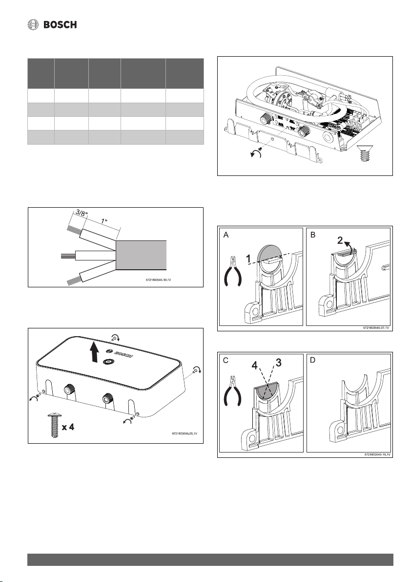
▶ Undo the retaining screws on the cover (x4) and remove the
cover of the unit.
Fig. 6
▶ Remove lower trim held by a single screw (Fig. 7).
Fig. 7
▶ Break off relevant plastic piece of lower trim to allow cable
to enter the product (Fig. 8 and fig. 9). For acceptable
installation positions and cable entry points fig. 13.
Fig. 8
Fig. 9
▶ Feed the cable through the cable grommet.
Model Rated
Voltage
(V)
Rated
Current
(A)
Minimum
required wire
Size (AWG)
Fuse
Protection
(A)
US3-2R 120 30 10
30
US4-2R 240 20 10
30
US7-2R 240 30 10
30
US9-2R 240 40
8 50
x 1
6721803545-06.1V
Loading ...
Loading ...
Loading ...