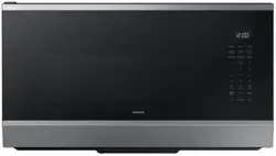
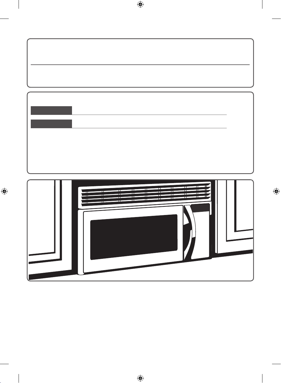
Installation Instructions
Over The Range Microwave Oven
BEFORE YOU BEGIN (Read these instructions completely and carefully.)
IMPORTANT
Save these instructions for local inspector’s use.
IMPORTANT
Observe all governing codes and ordinances.
• Note to Installer - Be sure to leave these instructions with the Consumer.
• Note to Consumer - Keep these instructions for future reference.
• Skill level - Installation of this appliance requires basic mechanical and electrical skills.
• Proper installation is the responsibility of the installer.
• Product failure due to improper installation is not covered under the Warranty.
READ CAREFULLY. KEEP THESE INSTRUCTIONS.
OTR_II_DE68-03587B-05_EN.indd 1 6/19/2019 3:55:58 PM

2
Contents
Step-by-step installation guideGeneral information
Important safety instructions . . . . . . . 3
Electrical requirements. . . . . . . . . . . 3
Hood exhaust . . . . . . . . . . . . . . . . 4
Damage - Shipment/Installation . . . . . . 6
Parts included. . . . . . . . . . . . . . . . 6
Tools you will need . . . . . . . . . . . . . 7
Mounting space. . . . . . . . . . . . . . . 7
1. Placement of the mounting plate . . . . 8
A. Removing the microwave oven from the
carton/Removing the mounting plate . . 8
B. Finding the wall studs. . . . . . . . . . . 8
C. Determining wall plate location under your
cabinet. . . . . . . . . . . . . . . . . . . 9
D. Aligning the wall plate. . . . . . . . . . 10
2. Installation types (choose A, B or C) . . 11
A. Outside top exhaust (vertical duct). . . 12
A1. Attach the mounting plate to the wall 12
A2. Use top cabinet template for preparation
of top cabinet . . . . . . . . . . . . 12
A3. Installation procedure for exhaust
adaptor and proper damper operation
check . . . . . . . . . . . . . . . . 13
A4. Mount the microwave oven . . . . 13
A5. Adjust the exhaust adaptor . . . . 14
A6. Connecting ductwork. . . . . . . . 14
B. Recirculating (non-vented ductless) . . 15
B1. Attach the mounting plate to the wall 15
B2. Use top cabinet template for preparation
of top cabinet . . . . . . . . . . . . 15
B3. Adapting microwave blower for
recirculation. . . . . . . . . . . . . 16
B4. Mount the microwave oven . . . . 17
B5. Installing the charcoal filter . . . . 18
C. Outside back exhaust (horizontal duct) 19
C1. Preparing the rear wall for outside back
exhaust . . . . . . . . . . . . . . . 19
C2. Attach the mounting plate to the wall 20
C3. Use top cabinet template for preparation
of top cabinet . . . . . . . . . . . . 20
C4. Adapting microwave blower for outside
back exhaust . . . . . . . . . . . . 20
C5. Mount the microwave oven . . . . 22
Before you use your microwave . . . . . 23
OTR_II_DE68-03587B-05_EN.indd 2 6/19/2019 3:55:59 PM
3
General information
IMPORTANT SAFETY INSTRUCTIONS
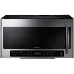
This product requires a three-prong grounded outlet.
The installer must perform a ground continuity
check on the power outlet box before beginning the
installation to insure that the outlet box is properly
grounded. If not properly grounded, or if the outlet
box does not meet electrical requirements noted
(under ELECTRICAL REQUIREMENTS), a qualified
electrician should be employed to correct any
deficiencies.
Insure proper
ground exists
before use
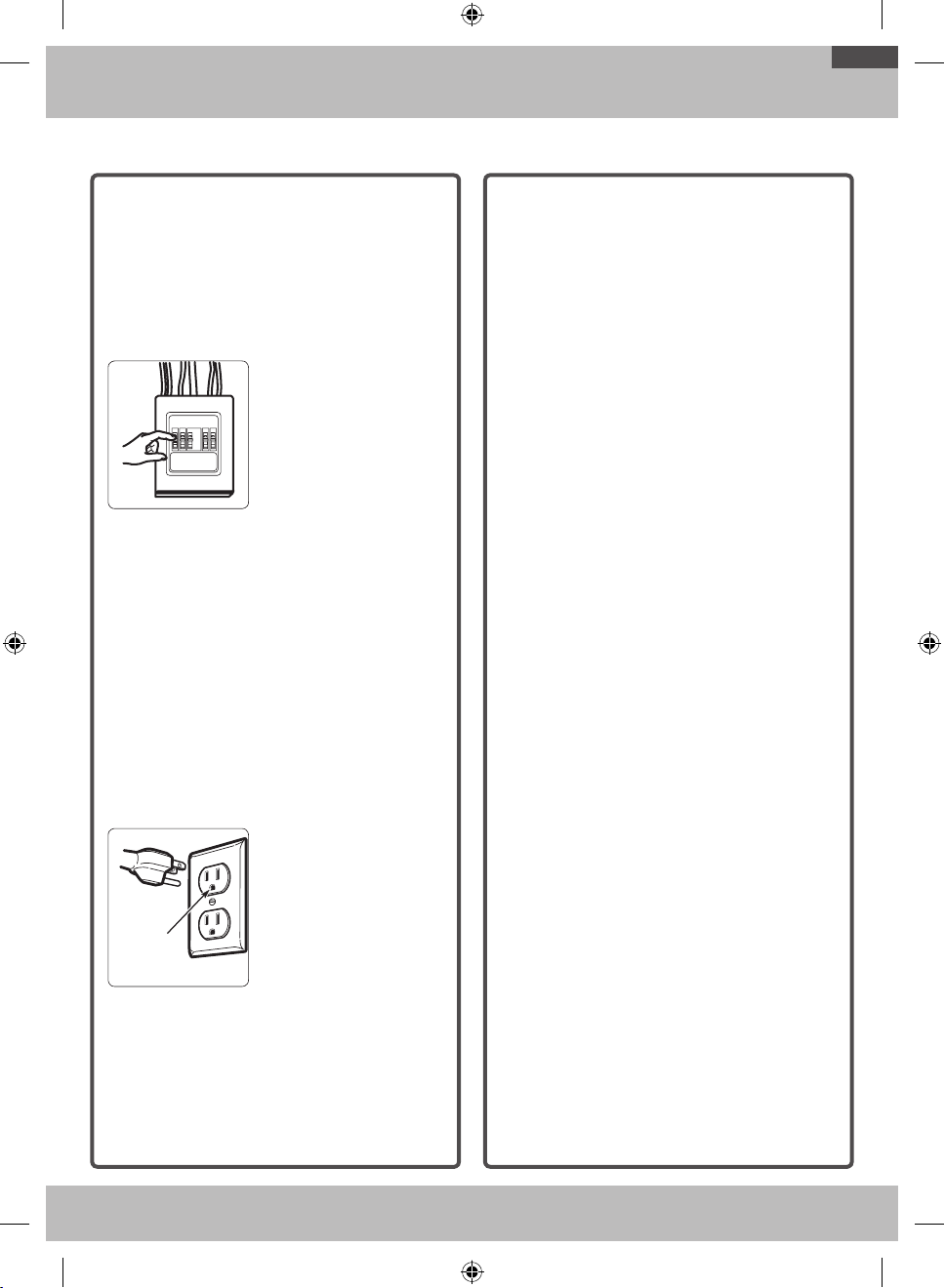
CAUTION: For personal
safety, remove house
fuse or open circuit
breaker before
beginning installation
to avoid severe or fatal
shock injury.
CAUTION: For personal safety, the mounting
surface must be capable of supporting the
cabinet load, in addition to the added weight of
this 63–85 pound product, plus additional oven
loads of up to 50 pounds or a total weight of
113–135 pounds.
CAUTION: For personal safety, this product cannot
be installed in cabinet arrangements such as an
island or a peninsula. It must be mounted to BOTH
a top cabinet AND a wall.
NOTE: For easier installation and personal safety,
it is recommended that two people install this
product.
IMPORTANT – PLEASE READ CAREFULLY. FOR
PERSONAL SAFETY, THIS APPLIANCE MUST BE
PROPERLY GROUNDED TO AVOID SEVERE OR
FATAL SHOCK.
Insure proper
ground exists
before use
Insure proper
ground exists
before use.
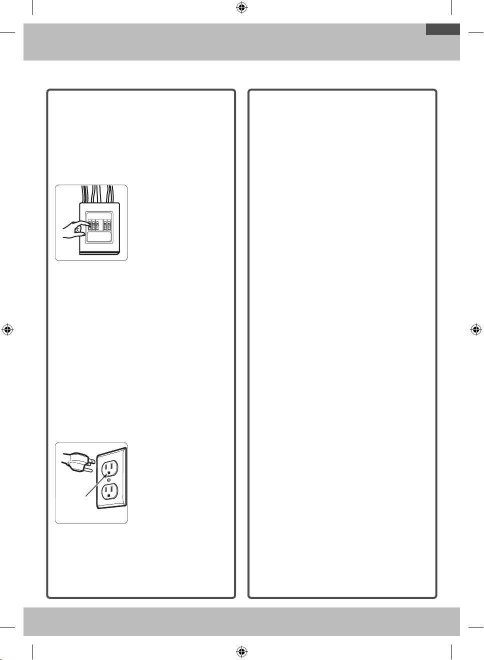
The power cord of this
appliance is equipped
with a three-prong
(grounding) plug which
mates with a standard
three-prong (grounding)
wall receptacle to
minimize the possibility
of electric shock hazard
from this appliance.
You should have the wall receptacle and circuit
checked by a qualified electrician to make sure
the receptacle is properly grounded.
Where a standard two-prong wall receptacle
is encountered, it is very important to have
it replaced with a properly grounded three-
prong wall receptacle, installed by a qualified
electrician.
DO NOT, UNDER ANY CIRCUMSTANCES, CUT,
DEFORM OR REMOVE ANY OF THE PRONGS
FROM THE POWER CORD. DO NOT USE WITH
AN EXTENSION CORD.
ELECTRICAL
REQUIREMENTS
Product rating is 120 volts AC, 60 Hertz,
13amps and 1.5 kilowatts. This product must be
connected to a supply circuit of the proper voltage
and frequency. Wire size must conform to the
requirements of the National Electrical Code or the
prevailing local code for this kilowatt rating. The
power supply cord and plug should be brought to a
separate branch circuit single grounded outlet of at
least 15 A and max of 20 A. The outlet box should
be located in the cabinet above the microwave oven.
The outlet box and supply circuit should be installed
by a qualified electrician and conform to the National
Electrical Code or the prevailing local code.
OTR_II_DE68-03587B-05_EN.indd 3 6/19/2019 3:55:59 PM
4
General information
NOTE: Read these next two pages only if you plan to vent your exhaust to the outside. If you plan to
recirculate the air back into the room, proceed to page 11.
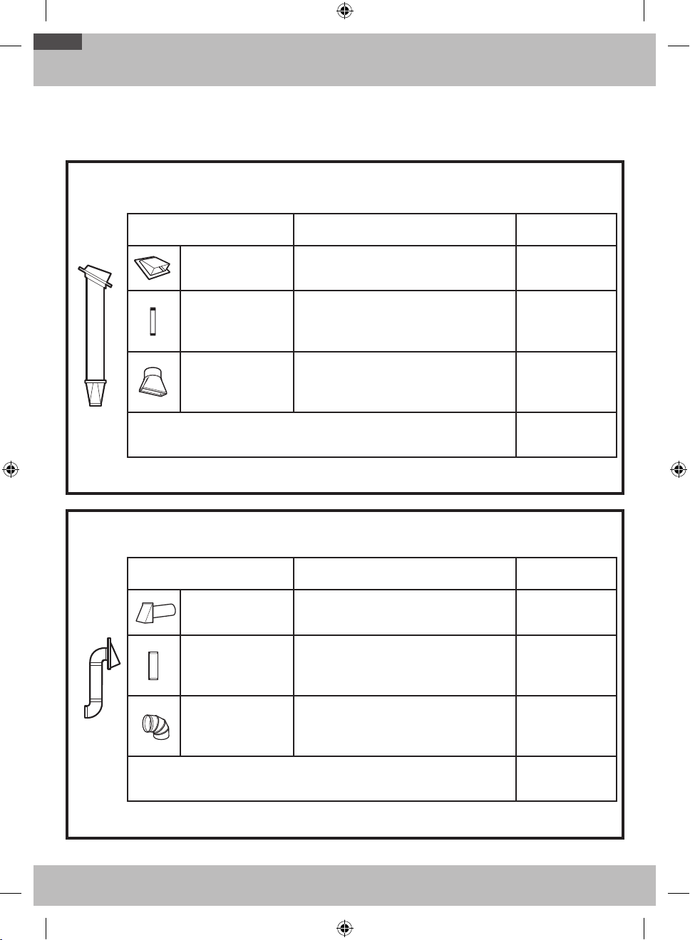
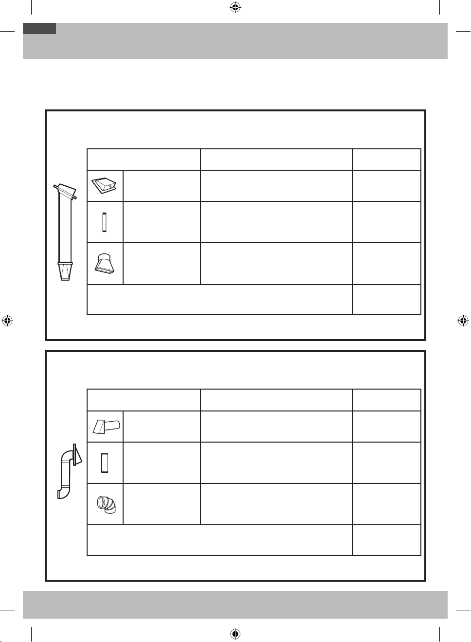
OUTSIDE TOP EXHAUST (EXAMPLE ONLY)
The following chart contains an example of one possible ductwork installation.
DUCT PIECES
EQUIVALENT
LENGTH
x
NUMBER
USED
=
EQUIVALENT
LENGTH
Roof Cap 24 ft. x (1) = 24 ft.
12 Ft. Straight Duct
(6
˝
Round)
12 ft. x (1) = 12 ft.
Rectangular-to-
Round Transition
Adaptor*
5 ft. x (1) = 5 ft.
Equivalent lengths of duct pieces are based on actual tests
and reflect requirements for good venting performance with
any vent hood.
Total Length = 41 ft.
* IMPORTANT: If a rectangular-to-round transition adaptor is used, the bottom corners of the damper will have to be
cut to fit, using the tin snips, in order to allow free movement of the damper.
OUTSIDE BACK EXHAUST (EXAMPLE ONLY)
The following chart contains an example of one possible ductwork installation.
DUCT PIECES
EQUIVALENT
LENGTH
x
NUMBER
USED
=
EQUIVALENT
LENGTH
Wall Cap 40 ft. x (1) = 40 ft.
3 Ft. Straight Duct (3¼˝
x 10˝ Rectangular)
3 ft. x (1) = 3 ft.
90° Elbow 10 ft. x (2) = 20 ft.
Equivalent lengths of duct pieces are based on actual tests
and reflect requirements for good venting performance with
any vent hood.
Total Length = 63 ft.
NOTE: For back exhaust, care should be taken to align exhaust with space between studs, or wall should be prepared
at the time it is constructed by leaving enough space between the wall studs to accommodate exhaust.
HOOD EXHAUST
OTR_II_DE68-03587B-05_EN.indd 4 6/19/2019 3:55:59 PM
5
General information
NOTE: If you need to install ducts, note that the total
duct length of 3¼˝ x 10˝ rectangular or 6˝ diameter
round duct should not exceed 140 equivalent feet.
Outside ventilation requires a HOOD EXHAUST DUCT.
Read the following carefully.
NOTE: It is important that venting be installed using
the most direct route and with as few elbows as
possible. This ensures clear venting of exhaust and
helps prevent blockages. Also, make sure dampers
swing freely and nothing is blocking the ducts.
Exhaust connection:
The hood exhaust has been designed to mate with a
standard 3¼˝ x 10˝ rectangular duct.
If a round duct is required, a rectangular-to-round
transition adaptor must be used. Do not use less
than a 6˝ diameter duct.
Maximum duct length:
For satisfactory air movement, the total duct length of
3¼˝ x 10˝ rectangular or 6˝ diameter round duct should
not exceed 140 equivalent feet.
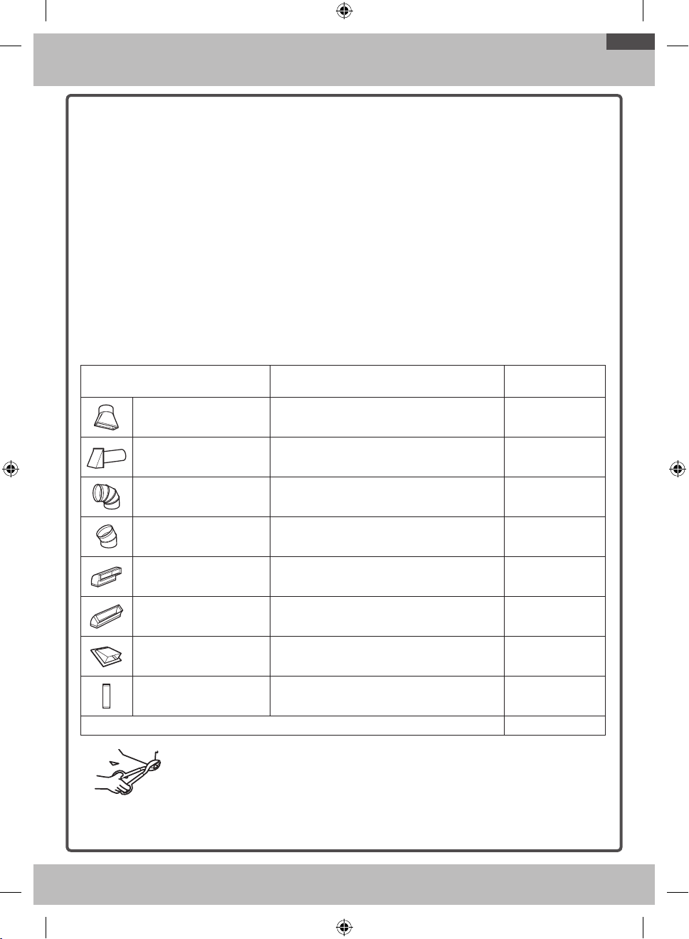
Elbows, transitions, wall and roof
caps, etc., present additional resistance to airflow
and are equivalent to a section of straight duct which is
longer than their actual physical size. When calculating
the total duct length, add the equivalent lengths of all
transitions and adaptors plus the length of all straight
duct sections. The chart below shows you how to
calculate total equivalent ductwork length using the
equivalent length in feet of some typical ducts.
DUCT PIECES
EQUIVALENT
LENGTH
x
NUMBER
USED
=
EQUIVALENT
LENGTH
Rectangular-to-Round
Transition Adaptor*
5 ft. x ( ) = ft.
Wall Cap 40 ft. x ( ) = ft.
90° Elbow 10 ft. x ( ) = ft.
45° Elbow 5 ft. x ( ) = ft.
90° Elbow 25 ft. x ( ) = ft.
45° Elbow 5 ft. x ( ) = ft.
Roof Cap 24 ft. x ( ) = ft.
Straight Duct 6˝ Round or 3¼˝
x 10˝ Rectangular
1 ft. x ( ) = ft.
Total Ductwork = ft.
* IMPORTANT: If a rectangular-to-round
transition adaptor is used, the bottom
corners of the damper will have to be cut
to fit, using tin snips, in order to allow free
movement of the damper.
Equivalent lengths of duct pieces
are based on actual tests and reflect
the requirements for good venting
performance with any vent hood.
OTR_II_DE68-03587B-05_EN.indd 5 6/19/2019 3:56:00 PM
6
General information
• If the unit is damaged in shipment, return the unit to the store in which it was bought for repair or
replacement.
• If the unit is damaged by the customer, repair or replacement is the responsibility of the customer.
• If the unit is damaged by the installer (if other than the customer), repair or replacement must be made by
arrangement between the customer and installer.
DAMAGE - SHIPMENT/INSTALLATION
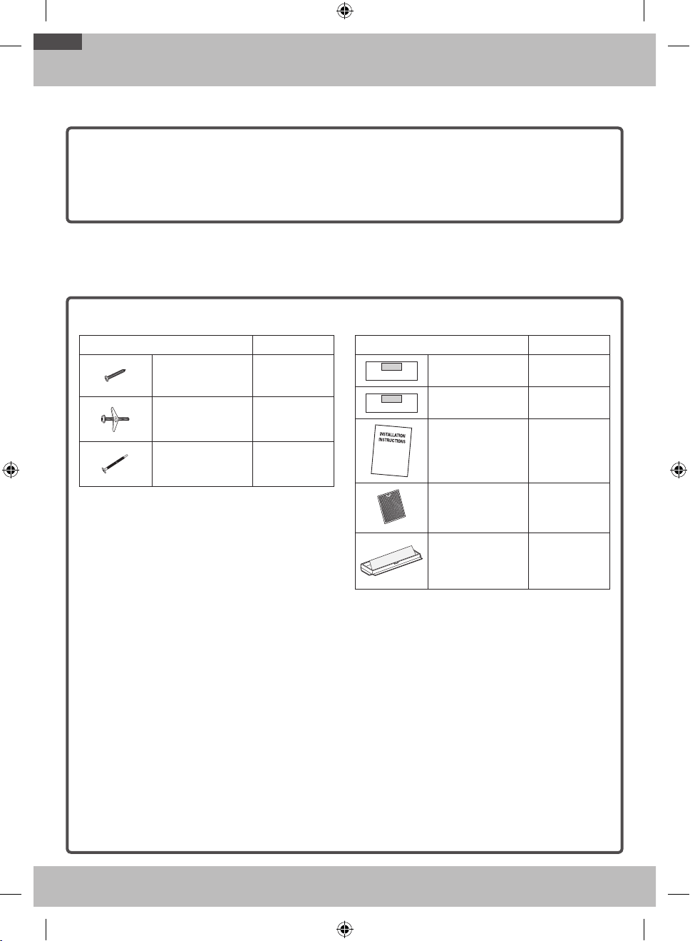
HARDWARE PACKET
PART QUANTITY
Template
INSTALLATION
INSTRUCTIONS
Wood Screws
(¼˝ x 2˝)
1
Template
INSTALLATION
INSTRUCTIONS
Toggle Bolts
(and wing nuts)
(
3
/
16
˝ x 3˝)
2
Template
INSTALLATION
INSTRUCTIONS
Self-aligning
Machine Screws
(¼˝ - 28 x 3¼˝)
2
You will find the installation hardware contained in a
packet with the unit. Check to make sure you have all
these parts.
NOTE: Some extra parts are included.
ADDITIONAL PARTS
PART QUANTITY
TOP CABINET TEMPLATE
REAR WALL TEMPLATE
Top Cabinet
Template
1
TOP CABINET TEMPLATE
REAR WALL TEMPLATE
Rear Wall Template 1
Installation
Instructions
1
Separately Packed
Grease Filter
2
Template
INSTALLATION
INSTRUCTIONS
Exhaust adaptor 1
PARTS INCLUDED
OTR_II_DE68-03587B-05_EN.indd 6 6/19/2019 3:56:00 PM

7
General information
# 1 and #2 Phillips
screwdriver
Pencil Ruler or tape measure and
straight edge
Carpenter square (optional)
Tin snips (for cutting
damper, if required)
Scissors (to cut
template, if necessary)
Electric drill with
3
/
16
˝, ½˝ and
⅝˝ drill bits
Filler blocks or scrap wood
pieces, if needed for top
cabinet spacing (used on
recessed bottom cabinet
installations only)
Gloves Saw (saber, hole or
keyhole)
Stud finder or Hammer
(optional)
Safety goggles
Level Duct and masking tape
TOOLS YOU WILL NEED
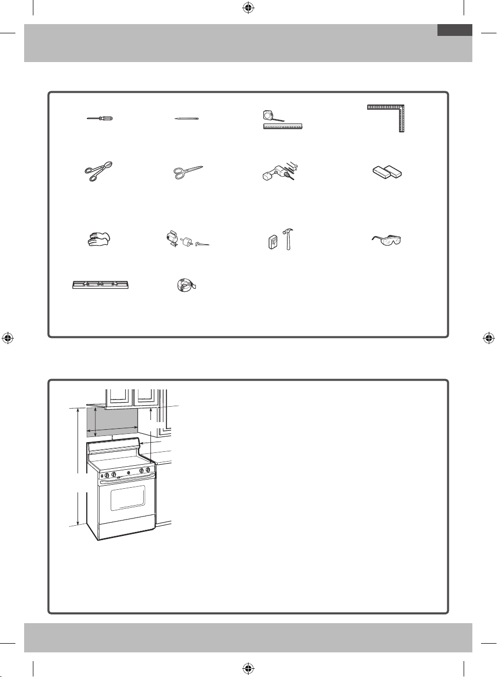
16½˝
30˝
2˝
30˝ min.
Bottom edge
of the cabinet
needs to be 30˝
or more from the
cooking surface.
Backsplash
66˝ or More
from the Floor
to the Top of the
Microwave
NOTES:
• The space between the cabinets must be 30˝ wide and
free of obstructions.
• If the space between the cabinets is greater than 30˝,
a Filler Panel Kit may be used to fill in the gap between
the microwave oven and the cabinets. Your Owner’s
Manual contains the kit number for your model.
• This microwave oven is for installation over ranges up
to 36˝ wide.
• If you are going to vent your microwave oven to the
outside, see the Hood Exhaust Section for exhaust
duct preparation.
• When installing the microwave oven beneath
smooth, flat cabinets, be careful to follow the
instructions on the top cabinet template for
power cord clearance.
MOUNTING SPACE
OTR_II_DE68-03587B-05_EN.indd 7 6/19/2019 3:56:01 PM
8
Step-by-step installation guide
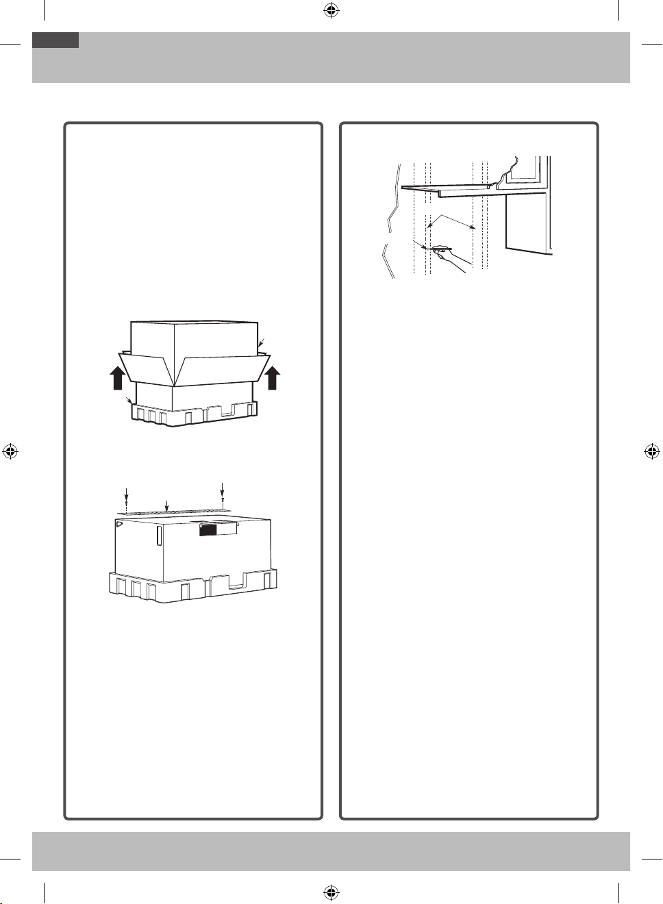
1. PLACEMENT OF THE MOUNTING PLATE
A. REMOVING THE
MICROWAVE OVEN FROM
THE CARTON/REMOVING
THE MOUNTING PLATE
1. Remove the installation instructions, Exhaust
adaptor, filters, glass tray, and the small
hardware bag. Do not remove the Styrofoam
protecting the front of the oven.
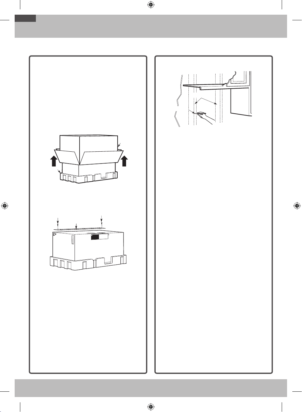
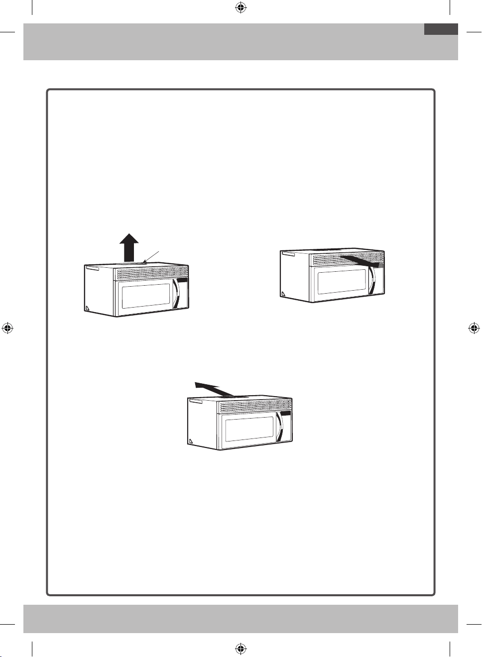
2. Fold back all 4 carton flaps fully against carton
sides. Then carefully roll the oven and carton
over onto the top side. The oven should be
resting in the Styrofoam.
Styrofoam
Carton
Carton
Styrofoam
3. Pull the carton up and o the oven.
4. Remove and properly discard plastic bags.
Screws
Screws
Mounting Plate
Screws
Mounting Plate
Screws
5. Remove the 2 screws from the mounting plate.
This plate will be used as the rear wall template
and for mounting.
NOTE: You will have to reuse two screws in original
loction of outcase after removing mounting plate.
B. FINDING THE WALL STUDS
Wall Studs
Center
Center
Wall Studs
1. Find the studs using one of the following
methods:
A. Stud finder–a magnetic device which locates
nails.
OR
B. Use a hammer to tap lightly across the
mounting surface to find a solid sound. This
will indicate a stud location.
2. After locating the stud(s), find the center by
probing the wall with a small nail to find the
edges of the stud. Then place a mark halfway
between the edges. The center of any adjacent
studs should be 16˝ or 24˝ from this mark.
3. Draw a line down the center of the studs.
THE MICROWAVE MUST BE CONNECTED TO
AT LEAST ONE WALL STUD.
OTR_II_DE68-03587B-05_EN.indd 8 6/19/2019 3:56:02 PM
9
Step-by-step installation guide
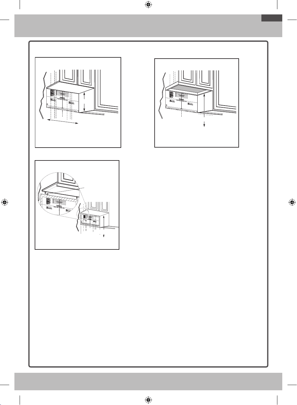
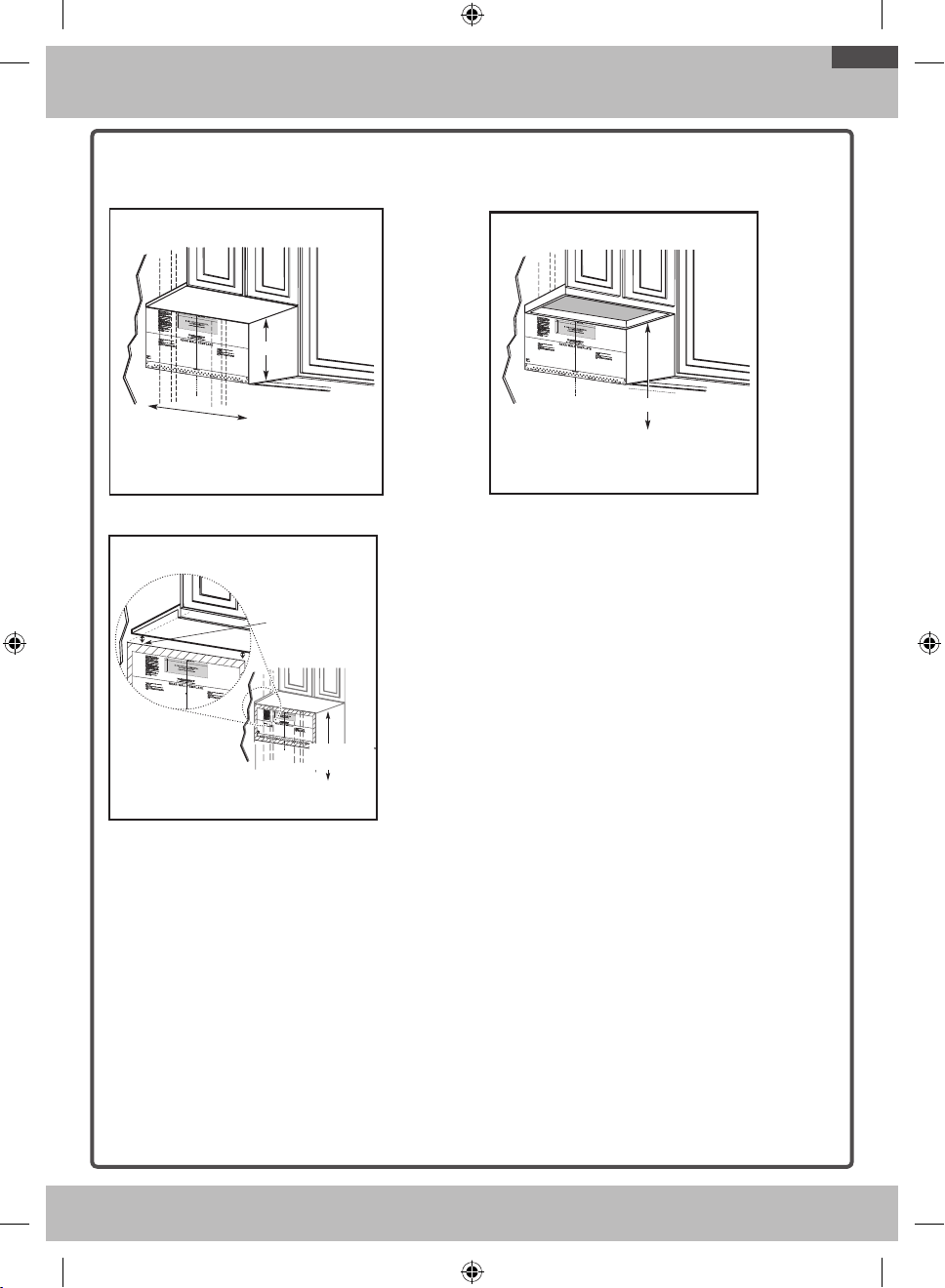
C. DETERMINING WALL PLATE LOCATION UNDER YOUR CABINET
C
L
Plate position – beneath flat bottom cabinet.
Draw a vertical line on the wall at
the center of the 30˝ wide space.
Tape the Rear Wall Template
onto the wall matching the
centerline and touching the
bottom of the cabinet.
At least 30˝
16½˝
C
L
Plate position – beneath framed recessed cabinet
bottom.
30˝ to Cooktop
Draw a vertical line on the wall at the center of the 30˝ wide
space.
Tape the Rear Wall Template onto the wall matching the centerline
and touching the bottom cabinet frame.
C
L
Plate position – beneath recessed bottom
cabinet with front overhang
Draw a line on the
back wall equal to the
depth of the front
overhang.
30" to Cooktop
Plate position – beneath recessed bottom cabinet with
front overhang.
30˝ to Cooktop
Draw a line on the
back wall equal to
the depth of the front
overhang.
Your cabinets may have decorative trim that interferes
with the microwave installation. Remove the decorative
trim to install the microwave properly and to make it
level.
THE MICROWAVE MUST BE LEVEL.
Use a level to make sure the cabinet bottom is level.
If the cabinets have a front overhang only, with no back
or side frame, install the mounting plate down the same
distance as the front overhang depth. This will keep the
microwave level.
1. Measure the inside depth of the front overhang.
2. Draw a horizontal line on the back wall an equal
distance below the cabinet bottom as the inside
depth of the front overhang.
3. For this type of installation with front overhang
only, align the mounting tabs with this horizontal
line, not touching the cabinet bottom as described
in Step D.
OTR_II_DE68-03587B-05_EN.indd 9 6/19/2019 3:56:04 PM

10
Step-by-step installation guide
D. ALIGNING THE WALL PLATE
C
L
CAUTION: Wear gloves to avoid cutting
fingers on sharp edges.
Area E
Hole B
Hole A
Centerline
notches
Draw a Vertical Line
on Wall from Center
of Top Cabinet
Draw a Horizontal line on wall from
bottom of “Rear Wall Template”.
Horizontal Line
Horizontal Line
Draw a Horizontal line on wall from bottom of “Rear
Wall Template”.
Draw a Vertical Line on
Wall from Center of Top
Cabinet
Horizontal Line
Horizontal Line Area E
Centerline
notches
Hole A
Hole B
CAUTION: Wear gloves to avoid cutting fingers
on sharp edges.
1. Draw a Vertical line on the wall at the center
of the 30” wide space.
2. Draw a Horizontal line on the wall at the
bottom of the “Rear Wall Template”.
3. Drill ⅝” holes for toggle bolts on 3 locations
(Hole A, Hole B, Hole C) but if the location of
hole is same as that of stud, drill a
3
/
16
˝ hole
for wood screw. In other words, toggle bolt
can not be used to the location of stud.
NOTE: DO NOT MOUNT THE PLATE AT
THIS TIME.
NOTE: Holes A, B and C are inside area E.
If none of A, B and C is in a stud, find a stud
somewhere in area E and draw a forth circle to
line up with the stud. It is important to use at
least one wood screw mounted firmly in a
stud to support the weight of the microwave. Set
the mounting plate aside.
OTR_II_DE68-03587B-05_EN.indd 10 6/19/2019 3:56:04 PM
11
Step-by-step installation guide
2. INSTALLATION TYPES (CHOOSE A, B OR C)
This microwave oven is compatible with the following
three types of ventilation:
A. Outside Top Exhaust (Vertical Duct)
B. Recirculating (Non-Vented Ductless)
C. Outside Back Exhaust (Horizontal Duct)
NOTE: This microwave is shipped assembled for
Outside Top Exhaust (except for non-vented models).
Select the type of ventilation required for your
installation and proceed to that section.
A. OUTSIDE TOP EXHAUST
(VERTICAL DUCT)
B. RECIRCULATING (NON-
VENTED DUCTLESS)
Adaptor in Place
for Outside
Top Exhaust
Adaptor in Place
for Outside Top
Exhaust
See page 12 See page 15
C. OUTSIDE BACK EXHAUST
(HORIZONTAL DUCT)
See page 19
OTR_II_DE68-03587B-05_EN.indd 11 6/19/2019 3:56:05 PM
12
Step-by-step installation guide
A. OUTSIDE TOP EXHAUST (VERTICAL DUCT)
INSTALLATION OVERVIEW
A1. Attach Mounting Plate to Wall
A2. Prepare Top Cabinet
A3. Mount the Microwave Oven
A4. Adjust the Exhaust Adaptor
A5. Connecting Ductwork
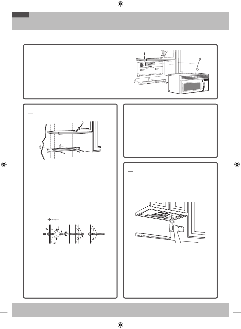
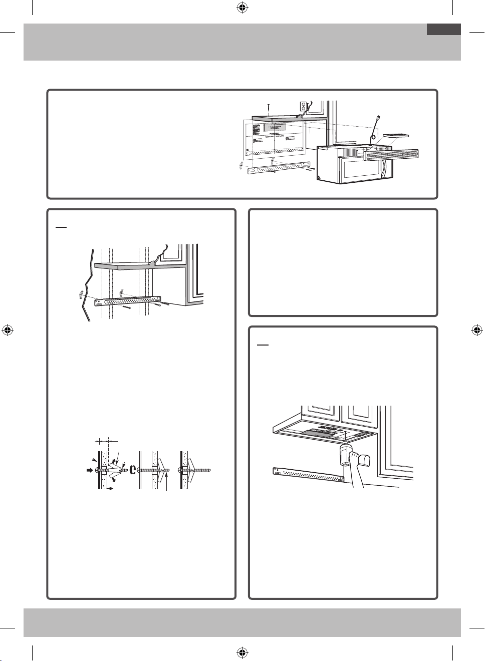
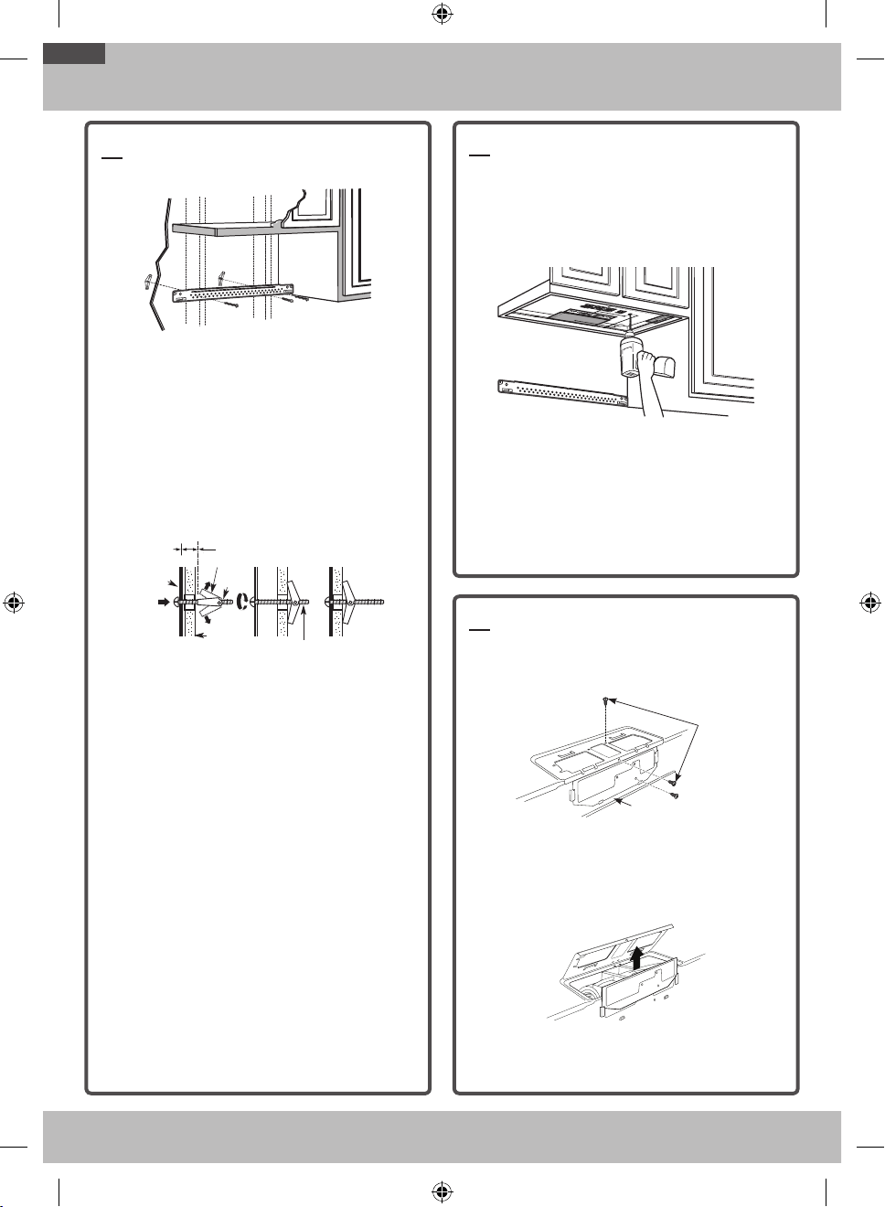
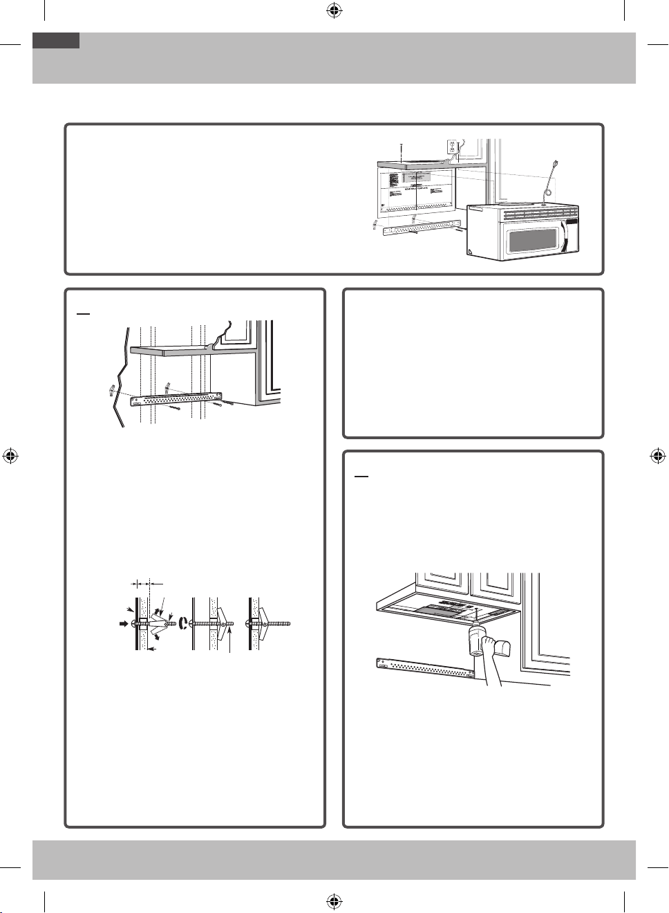
A1. ATTACH THE MOUNTING PLATE
TO THE WALL
Attach the plate to the wall using toggle bolts. At
least one wood screw must be used to attach the
plate to a wall stud.
1. Remove the toggle wings from the bolts.
2. Insert the bolts into the mounting plate through
the holes designated to go into drywall, and then
reattach the toggle wings to ¾˝ onto each bolt.
To use toggle bolts:
Wall
Toggle Wings
Toggle
Bolt
Bolt End
Spacing for Toggles More
Than Wall Thickness
Mounting
Plate
Spacing for Toggles More
Than Wall Thickness
Bolt End
Mounting
Plate
Toggle
Bolt
Wall
Toggle Wings
3. Place the mounting plate against the wall and
insert the toggle wings into the holes in the wall
to mount the plate.
NOTE: Before tightening toggle bolts and wood
screw, make sure the tabs on the mounting plate
touch the bottom of the cabinet when pushed
flush against the wall and that the plate is properly
centered under the cabinet.
CAUTION: Be careful to avoid pinching your fingers
between the back of the mounting plate and the wall.
4. Tighten all bolts. Pull the plate away from the
wall to help tighten the bolts.
A2. USE TOP CABINET TEMPLATE
FOR PREPARATION OF TOP
CABINET
You need to drill holes for the top support screws, a
hole large enough for the power cord to fit through,
and a cutout large enough for the exhaust adaptor.
• Read the instructions on the TOP CABINET
TEMPLATE.
• Tape it underneath the top cabinet.
• Drill the holes, following the instructions on the
TOP CABINET TEMPLATE.
CAUTION: Wear safety goggles when drilling holes
in the cabinet bottom.
OTR_II_DE68-03587B-05_EN.indd 12 6/19/2019 3:56:06 PM
13
Step-by-step installation guide
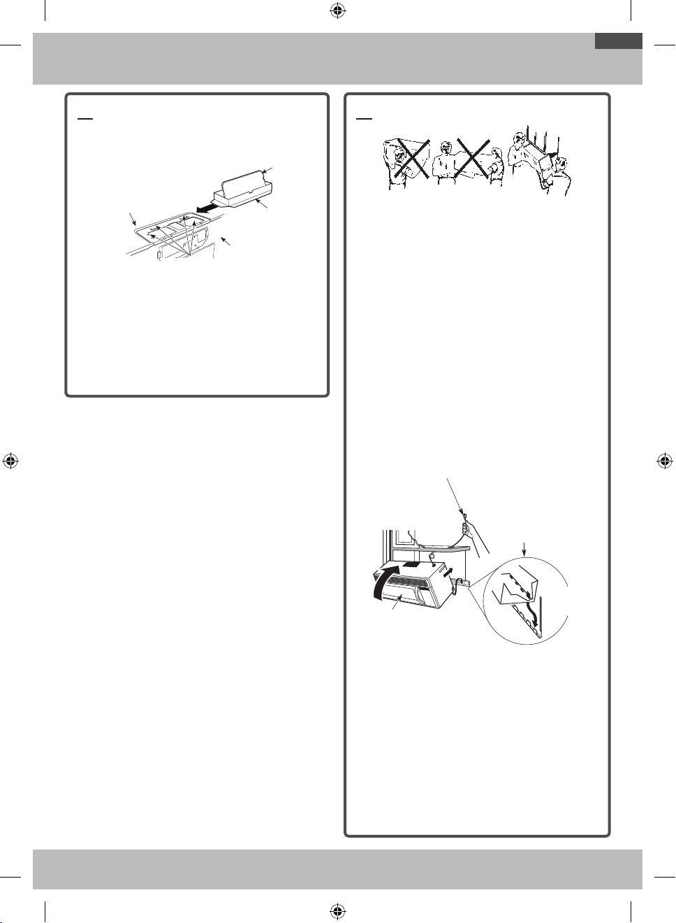
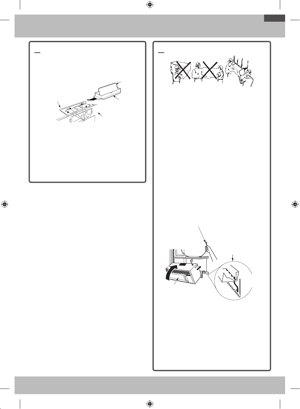
A3. INSTALLATION PROCEDURE FOR
EXHAUST ADAPTOR AND PROPER
DAMPER OPERATION CHECK
Blower Plate
Damper
Exhaust Adaptor
Retaining Hooks
Back of
Microwave
Oven
• Read the instructions on the TOP CABINET
TEMPLATE.
• Tape it underneath the top cabinet.
• Drill the holes, following the instructions on the
TOP CABINET TEMPLATE.
CAUTION: Wear safety goggles when drilling holes
in the cabinet bottom.
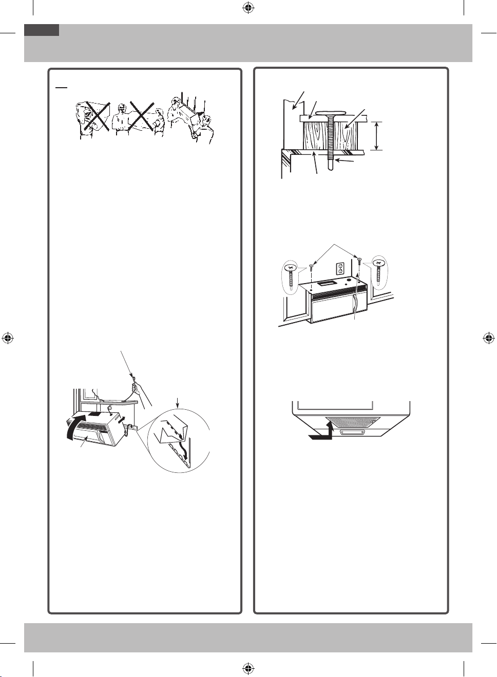
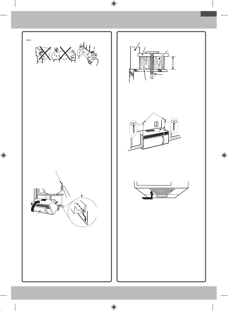
A4. MOUNT THE MICROWAVE OVEN
FOR EASIER INSTALLATION AND PERSONAL
SAFETY, WE RECOMMEND THAT TWO PEOPLE
INSTALL THIS MICROWAVE OVEN.
IMPORTANT: Do not grip or use the handle
during installation.
NOTE: If your cabinet is metal, use the nylon
grommet around the power cord hole to prevent
cutting of the cord.
NOTE: We recommend using filler blocks if the
cabinet front hangs below the cabinet bottom shelf.
IMPORTANT: If filler blocks are not used, case
damage may occur from over tightening screws.
NOTE: When mounting the microwave oven, thread
power cord through hole in bottom of top cabinet.
Keep it tight throughout Steps 1-3. Do not pinch cord
or lift oven by pulling cord.
1. Lift microwave, tilt it
forward, and hook slots
at back bottom edge
onto four lower tabs of
mounting plate.
2. Rotate front of
oven up against
cabinet bottom.
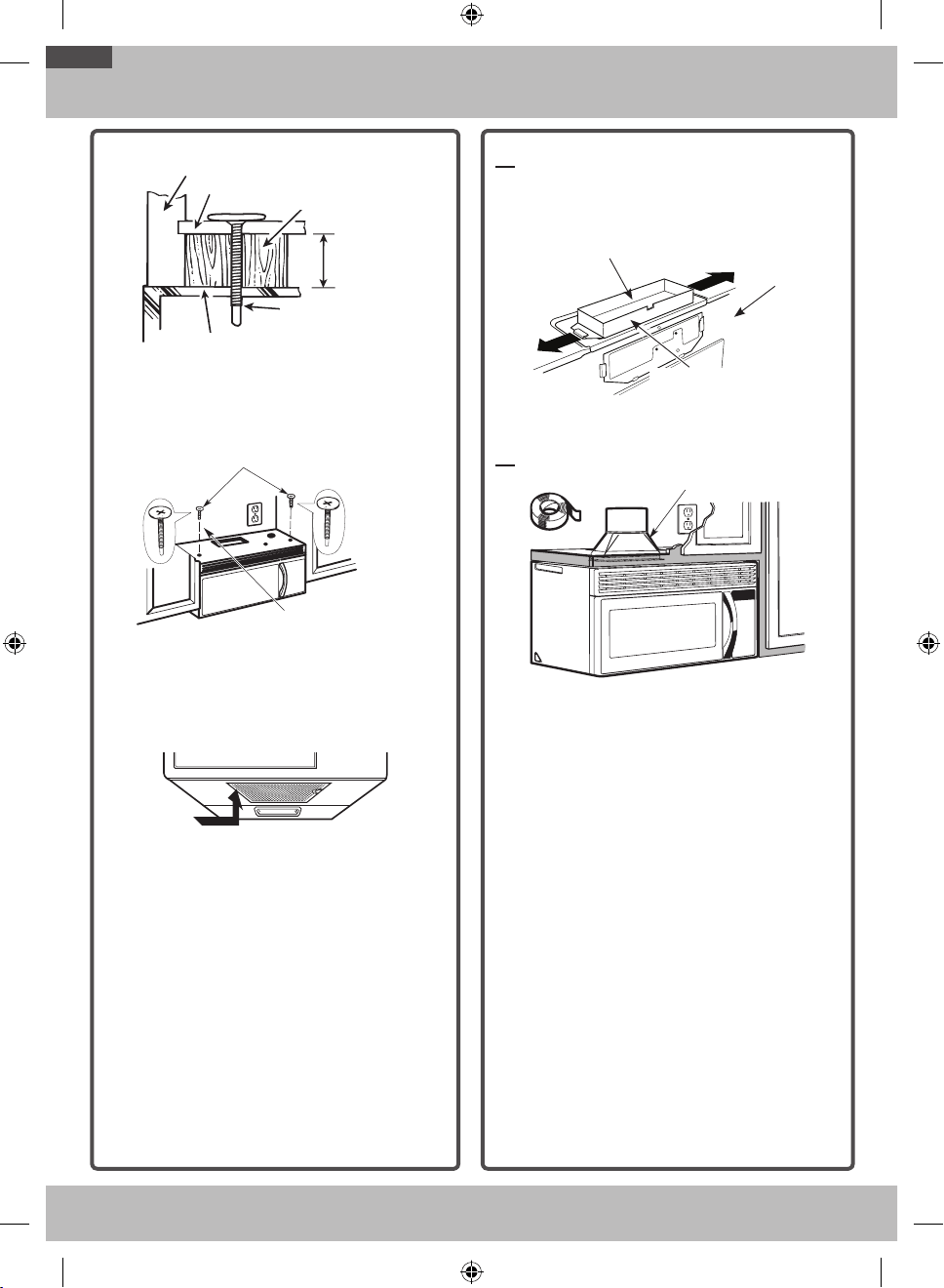
3. Insert a self-aligning screw through the top
center cabinet hole. Temporarily secure the oven
by turning the screw at least two full turns after
the threads have engaged. (It will be completely
tightened later.) Be sure to keep power cord
tight. Be careful not to pinch the cord,
especially when mounting flush to bottom of
cabinet.
OTR_II_DE68-03587B-05_EN.indd 13 6/19/2019 3:56:06 PM
14
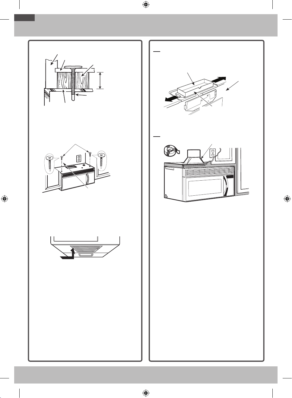
Step-by-step installation guide
Cabinet Front
Filler Block
Microwave Oven Top
Self-Aligning Screw
Equivalent to
Depth of
Cabinet Recess
Cabinet Bottom Shelf
Equivalent
to Depth of
Cabinet Recess
Cabinet Bottom Shelf
Microwave Oven Top
Cabinet Front
Filler Block
Self-Aligning Screw
4. Attach the microwave oven to the top cabinet.
5. Insert 2 self-aligning screws
through outer top cabinet
holes. Turn two full turns on
each screw.
6. Tighten center screw
completely.
7. Tighten the outer two screws to the top of the
microwave oven. (While tightening screws, hold
the microwave oven in place against the wall and
the top cabinet.)
8. Install grease filter. See the Owner’s Manual
packed with the microwave.
A5. ADJUST THE EXHAUST ADAPTOR
Open the top cabinet and adjust the exhaust adaptor
to connect to the house duct.
Damper
For Side-toSide
Adjustment,
Slide the Exhaust
Adaptor as Needed
Back of
Microwave
Oven
A6. CONNECTING DUCTWORK
House Duct
House Duct
1. Extend the house duct down to connect to the
exhaust adaptor.
2. Seal exhaust duct joints using duct tape.
OTR_II_DE68-03587B-05_EN.indd 14 6/19/2019 3:56:07 PM
15
Step-by-step installation guide
B. RECIRCULATING (NON-VENTED DUCTLESS)
INSTALLATION OVERVIEW
B1. Attach Mounting Plate to Wall
B2. Prepare Top Cabinet
B3. Adjust Blower
B4. Mount Microwave Oven
B5. Install Charcoal Filter
B1. ATTACH THE MOUNTING PLATE
TO THE WALL
Attach the plate to the wall using toggle bolts. At
least one wood screw must be used to attach the
plate to a wall stud.
1. Remove the toggle wings from the bolts.
2. Insert the bolts into the mounting plate through
the holes designated to go into drywall, and then
reattach the toggle wings to ¾˝ onto each bolt.
To use toggle bolts:
Wall
Toggle Wings
Toggle
Bolt
Bolt End
Spacing for Toggles More
Than Wall Thickness
Mounting
Plate
Spacing for Toggles More
Than Wall Thickness
Bolt End
Mounting
Plate
Toggle
Bolt
Wall
Toggle Wings
3. Place the mounting plate against the wall and
insert the toggle wings into the holes in the wall
to mount the plate.
NOTE: Before tightening toggle bolts and wood
screw, make sure the tabs on the mounting plate
touch the bottom of the cabinet when pushed
flush against the wall and that the plate is properly
centered under the cabinet.
CAUTION: Be careful to avoid pinching your fingers
between the back of the mounting plate and the wall.
4. Tighten all bolts. Pull the plate away from the
wall to help tighten the bolts.
B2. USE TOP CABINET TEMPLATE
FOR PREPARATION OF TOP
CABINET
You need to drill holes for the top support screws
and a hole large enough for the power cord to fit
through.
• Read the instructions on the TOP CABINET
TEMPLATE.
• Tape it underneath the top cabinet.
• Drill the holes, following the instructions on the
TOP CABINET TEMPLATE.
CAUTION: Wear safety goggles when drilling holes
in the cabinet bottom.
OTR_II_DE68-03587B-05_EN.indd 15 6/19/2019 3:56:08 PM
16
Step-by-step installation guide
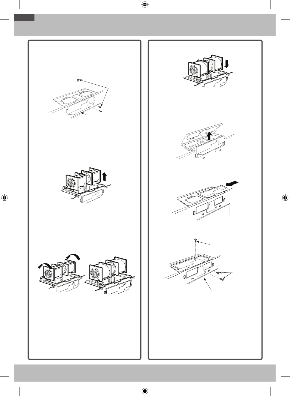
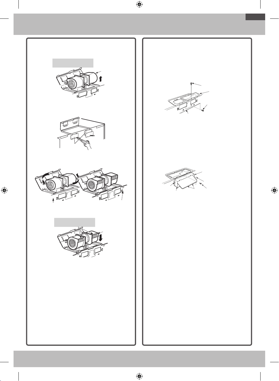
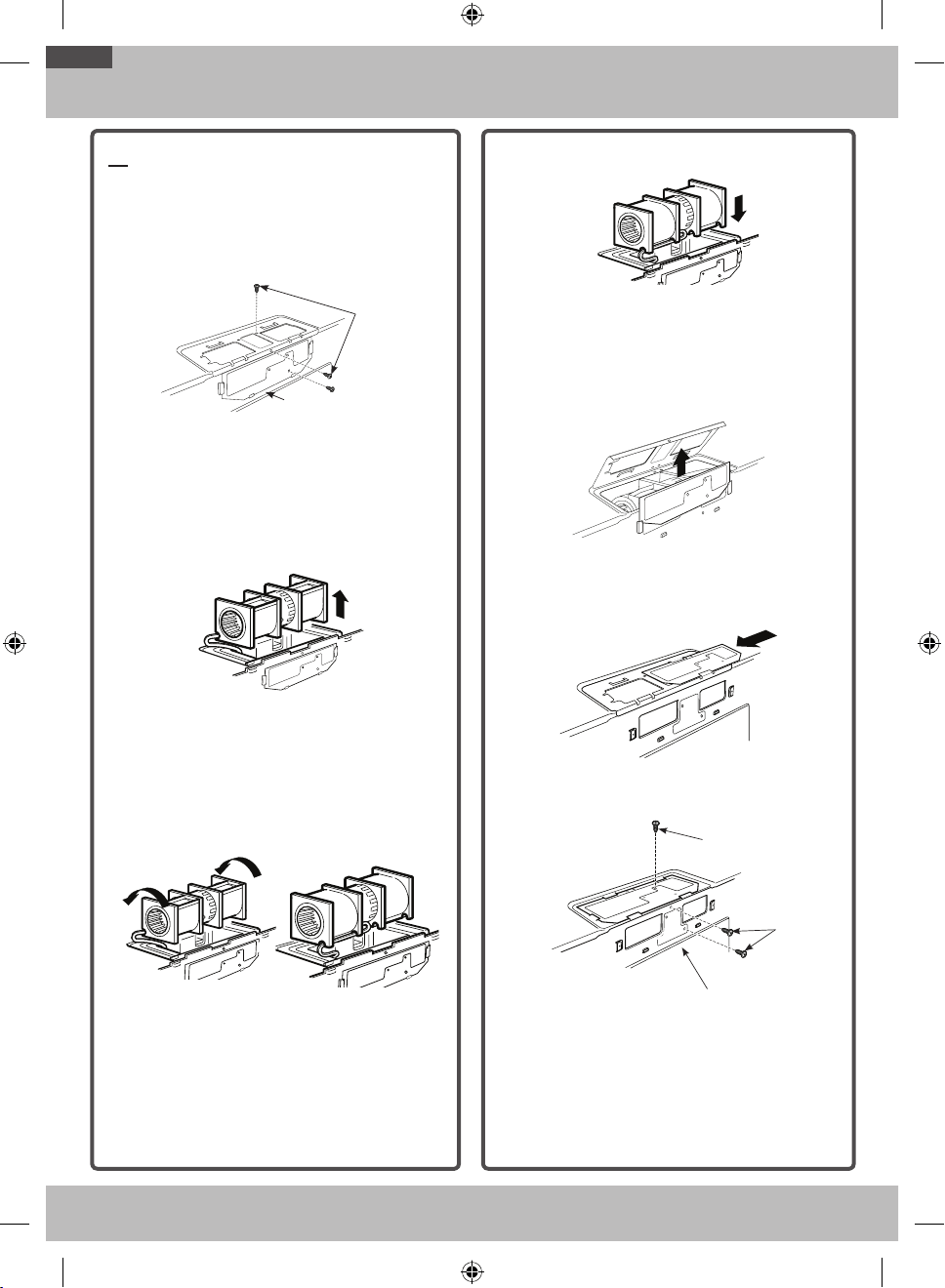
B3. ADAPTING MICROWAVE BLOWER
FOR RECIRCULATION
1. Remove and save screw that holds blower plate to
microwave.
2. Lift up the blower plate.
Back of
Microwave Oven
Blower
Retaining
Screws
NOTE: The exhaust adaptor with damper is not
needed for recirculating models. You may want to
save them for possible future use.
3. Carefully pull out the blower unit. The wires will
extend far enough to allow you to adjust the
blower unit.
CAUTION: Do not touch blade of blower
forpreventing crack and break. Hold outer case when
the blower pull out or back into.
4. Roll the blower unit 90° so that fan blade
openings are facing toward the front of the
microwave.
Before Roll
After Roll
5. Place the blower unit back into the opening.
CAUTION: Do not pull or stretch the blower unit
wiring. Make sure the wires are not pinched.
6. Remove the metal vent fan cover on the back of
the microwave by sliding it up.
7. Close the blower door. Slide blower shield onto
the top of the blower door opening.
8. Secure the blower to the microwave using the
blower retaining screws from Step 1.
Back of
Microwave Oven
Blower
Retaining
Screws
Blower Retaining
Screw
OTR_II_DE68-03587B-05_EN.indd 16 6/19/2019 3:56:10 PM
17
Step-by-step installation guide
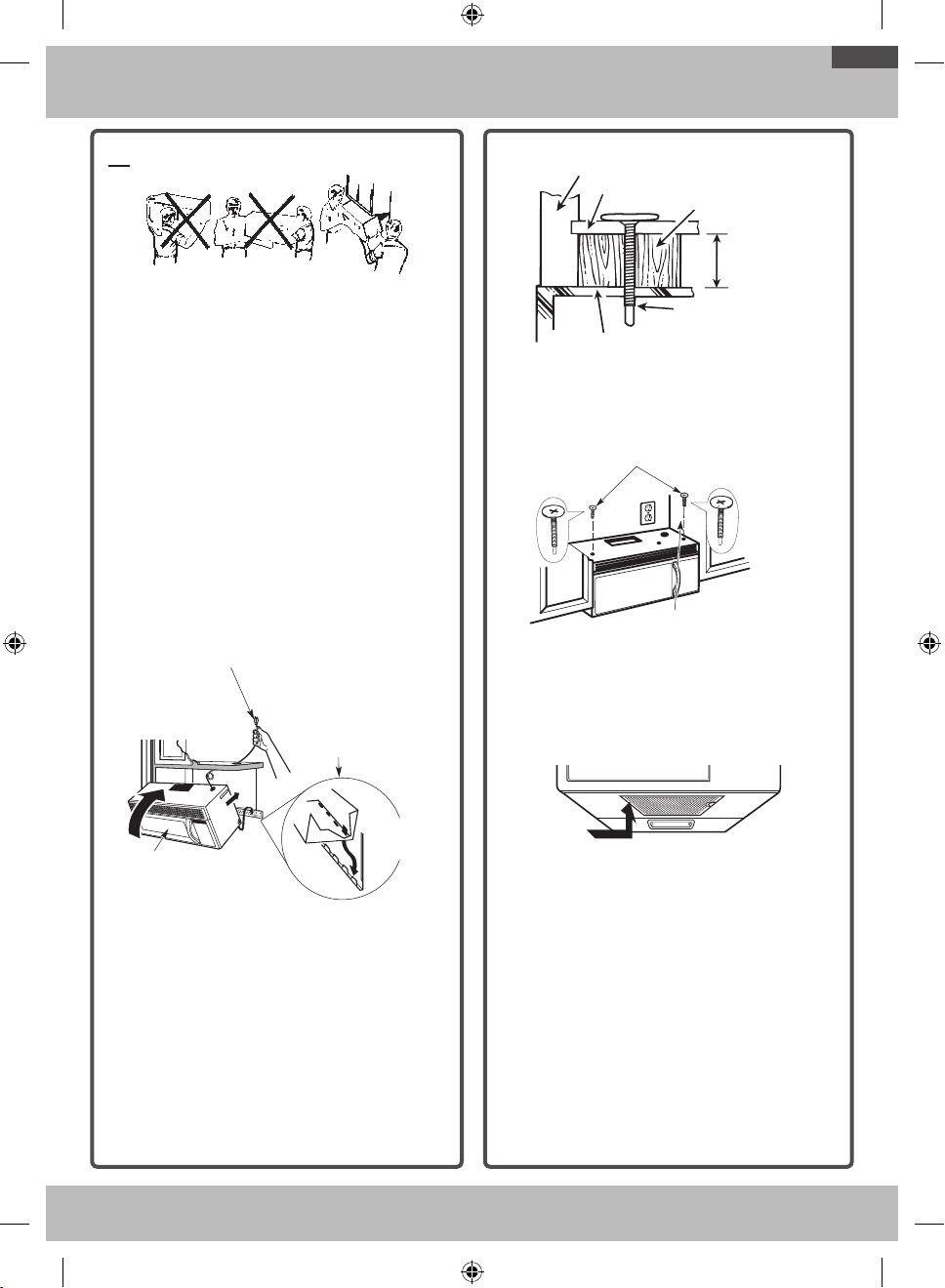
B4. MOUNT THE MICROWAVE OVEN
FOR EASIER INSTALLATION AND PERSONAL
SAFETY, WE RECOMMEND THAT TWO PEOPLE
INSTALL THIS MICROWAVE OVEN.
IMPORTANT: Do not grip or use the handle
during installation.
NOTE: If your cabinet is metal, use the nylon
grommet around the power cord hole to prevent
cutting of the cord.
NOTE: We recommend using filler blocks if the
cabinet front hangs below the cabinet bottom shelf.
IMPORTANT: If filler blocks are not used, case
damage may occur from over tightening screws.
NOTE: When mounting the microwave oven, thread
power cord through hole in bottom of top cabinet.
Keep it tight throughout Steps 1-3. Do not pinch cord
or lift oven by pulling cord.
1. Lift microwave, tilt it
forward, and hook slots
at back bottom edge
onto four lower tabs of
mounting plate.
2. Rotate front of oven
up against cabinet
bottom.
3. Insert a self-aligning screw through the top
center cabinet hole. Temporarily secure the oven
by turning the screw at least two full turns after
the threads have engaged. (It will be completely
tightened later.) Be sure to keep power cord
tight. Be careful not to pinch the cord,
especially when mounting flush to bottom of
cabinet.
Cabinet Front
Filler Block
Microwave Oven Top
Self-Aligning Screw
Equivalent to
Depth of
Cabinet Recess
Cabinet Bottom Shelf
Equivalent
to Depth of
Cabinet Recess
Cabinet Bottom Shelf
Microwave Oven Top
Cabinet Front
Filler Block
Self-Aligning Screw
4. Attach the microwave oven to the top cabinet.
5. Insert 2 self-aligning screws
through outer top cabinet
holes. Turn two full turns on
each screw.
6. Tighten center screw
completely.
7. Tighten the outer two screws to the top of the
microwave oven. (While tightening screws, hold
the microwave oven in place against the wall and
the top cabinet.)
8. Install grease filter. See the Owner’s Manual
packed with the microwave.
OTR_II_DE68-03587B-05_EN.indd 17 6/19/2019 3:56:11 PM
18
Step-by-step installation guide
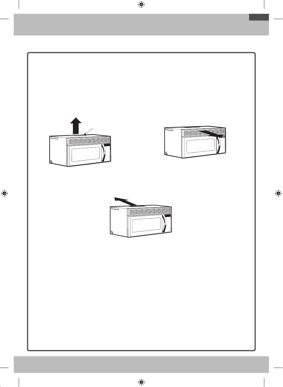
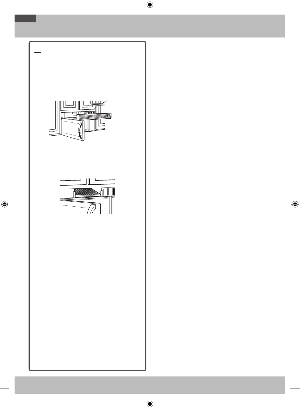
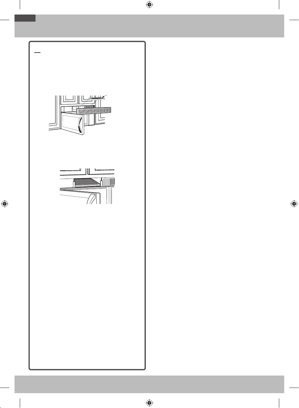
B5. INSTALLING THE CHARCOAL
FILTER
1. Remove screws on top of grille using a #1
Phillips screwdriver.
2. Open the door.
3. Remove the grill.
• After push left, Pull the straight o.
Charcoal filter
4. Install the charocal filter. When properly installed,
the wire mesh of the filter should be visible from
the front.
5. Reinstall the grille and the screws.
6. Close the door.
Insert mesh-side up
OTR_II_DE68-03587B-05_EN.indd 18 6/19/2019 3:56:11 PM
19
Step-by-step installation guide
C. OUTSIDE BACK EXHAUST (HORIZONTAL DUCT)
INSTALLATION OVERVIEW
C1. Prepare Rear Wall
C2. Attach Mounting Plate to Wall
C3. Prepare Top Cabinet
C4. Adjust Blower
C5. Mount the Microwave Oven
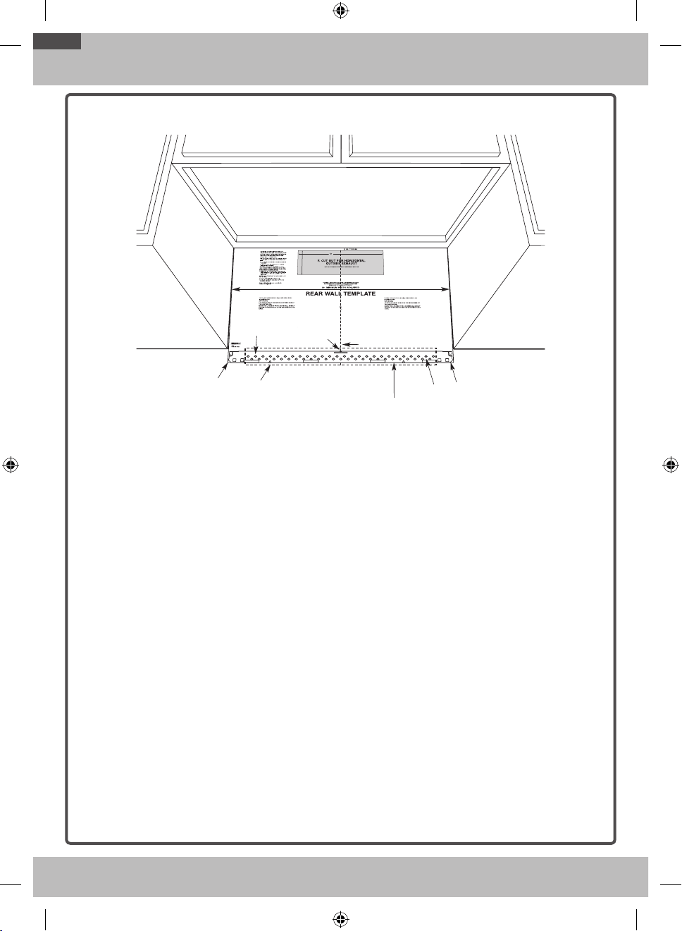
C1. PREPARING THE REAR WALL FOR
OUTSIDE BACK EXHAUST
You need to cut an opening in the rear wall for
outside exhaust.
C
L
• Read the instructions on the REAR WALL
TEMPLATE.
• Tape it to the rear wall.
• Cut the opening, following the instructions of the
REAR WALL TEMPLATE.
OTR_II_DE68-03587B-05_EN.indd 19 6/19/2019 3:56:12 PM
20
Step-by-step installation guide
C2. ATTACH THE MOUNTING PLATE
TO THE WALL
Attach the plate to the wall using toggle bolts. At
least one wood screw must be used to attach the
plate to a wall stud.
1. Remove the toggle wings from the bolts.
2. Insert the bolts into the mounting plate through
the holes designated to go into drywall, and then
reattach the toggle wings to ¾˝ onto each bolt.
To use toggle bolts:
Wall
Toggle Wings
Toggle
Bolt
Bolt End
Spacing for Toggles More
Than Wall Thickness
Mounting
Plate
Spacing for Toggles More
Than Wall Thickness
Bolt End
Mounting
Plate
Toggle
Bolt
Wall
Toggle Wings
3. Place the mounting plate against the wall and
insert the toggle wings into the holes in the wall
to mount the plate.
NOTE: Before tightening toggle bolts and wood
screw, make sure the tabs on the mounting plate
touch the bottom of the cabinet when pushed
flush against the wall and that the plate is properly
centered under the cabinet.
CAUTION: Be careful to avoid pinching your fingers
between the back of the mounting plate and the wall.
4. Tighten all bolts. Pull the plate away from the
wall to help tighten the bolts.
C3. USE TOP CABINET TEMPLATE
FOR PREPARATION OF TOP
CABINET
You need to drill holes for the top support screws, a
hole large enough for the power cord to fit through,
and a cutout large enough for the exhaust adaptor.
• Read the instructions on the TOP CABINET
TEMPLATE.
• Tape it underneath the top cabinet.
• Drill the holes, following the instructions on the
TOP CABINET TEMPLATE.
CAUTION: Wear safety goggles when drilling holes
in the cabinet bottom.
C4. ADAPTING MICROWAVE BLOWER
FOR OUTSIDE BACK EXHAUST
1. Remove and save screws that hold the blower
plate and the blower motor to the microwave.
Back of
Microwave Oven
Blower
Retaining
Screws
2 Open the blower door by lifting it up at the back
of the microwave. Remove and save the blower
shield on the back of the microwave by sliding it
up. Remove and save the metal vent fan cover
on the back of the microwave by sliding it up.
OTR_II_DE68-03587B-05_EN.indd 20 6/19/2019 3:56:12 PM
21
Step-by-step installation guide
3. Carefully pull out the blower unit. The wires will
extend far enough to allow you to adjust the
blower unit.
BEFORE: Fan Blade
Openings Facing Forward
End B
End A
4. Remove Parts “A” with tin snips or pliers.
(On Some Model)
Parts “A”
5. Rotate blower unit counterclockwise 180°.
Before Rotation After Rotation
Back of Microwave
Back of Microwave
6. Place the blower unit back into the opening.
AFTER: Fan Blade Openings
Facing Back
End B
End A
CAUTION: Do not pull or stretch the blower unit
wiring. Make sure the wires are not pinched.
NOTE: The blower unit exhaust openings should
match exhaust openings on rear of microwave
oven.
7. Replace the blower plate in the same position as
before with the screw.
8. Close the blower door. Slide blower shield onto
the top of the blower door opening. Secure the
blower to the microwave oven using the blower
retaining screws from Step 1 except the upper
blower motor retaining screw.
Blower
Retaining Screw
Blower
Shield
Blower
Retaining Screw
Back of
Microwave Oven
9. Slide the exhaust adaptor onto the back of the
microwave oven, securing it into the lower locking
tabs. Take care to ensure that the damper hinge
is installed so that it is at the top and that the
damper swings freely. Reinstall the upper blower
motor screw through the adaptor and the blower
door and into the back of the microwave oven.
Guide
Guide
Adaptor
Locking Tabs
(not shown)
Blower Motor Door
Retaining Screw
Back of
Microwave Oven
OTR_II_DE68-03587B-05_EN.indd 21 6/19/2019 3:56:14 PM
22
Step-by-step installation guide
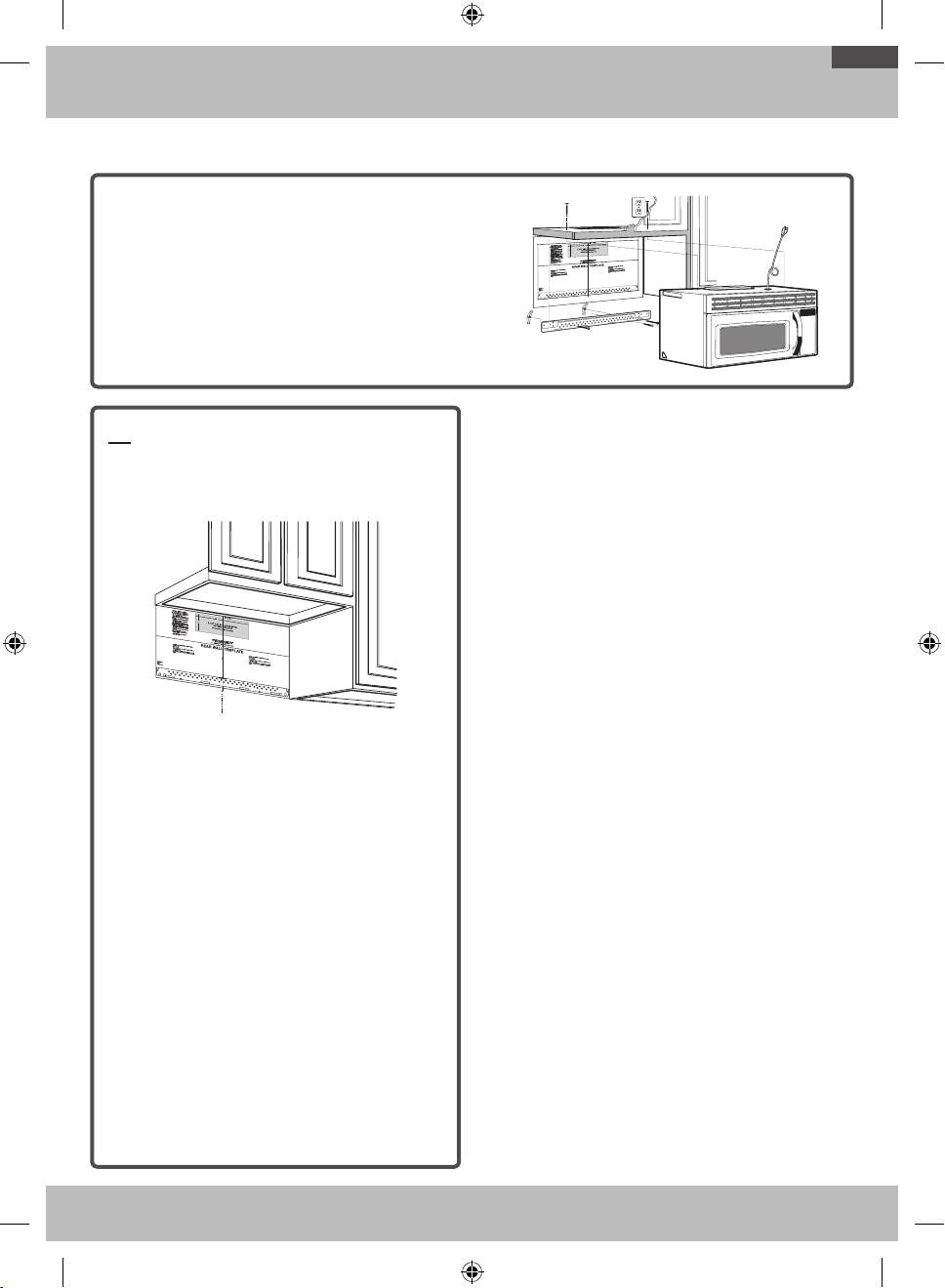
C5. MOUNT THE MICROWAVE OVEN
FOR EASIER INSTALLATION AND PERSONAL
SAFETY, WE RECOMMEND THAT TWO PEOPLE
INSTALL THIS MICROWAVE OVEN.
IMPORTANT: Do not grip or use the handle
during installation.
NOTE: If your cabinet is metal, use the nylon
grommet around the power cord hole to prevent
cutting of the cord.
NOTE: We recommend using filler blocks if the
cabinet front hangs below the cabinet bottom shelf.
IMPORTANT: If filler blocks are not used, case
damage may occur from over tightening screws.
NOTE: When mounting the microwave oven, thread
power cord through hole in bottom of top cabinet.
Keep it tight throughout Steps 1-3. Do not pinch cord
or lift oven by pulling cord.
1. Lift microwave, tilt it
forward, and hook slots
at back bottom edge
onto four lower tabs of
mounting plate.
2. Rotate front of oven
up against cabinet
bottom.
3. Insert a self-aligning screw through the top center
cabinet hole. Temporarily secure the oven by
turning the screw at least two full turns after
the threads have engaged. (It will be completely
tightened later.) Be sure to keep power cord
tight. Be careful not to pinch the cord,
especially when mounting flush to bottom of
cabinet.
Cabinet Front
Filler Block
Microwave Oven Top
Self-Aligning Screw
Equivalent to
Depth of
Cabinet Recess
Cabinet Bottom Shelf
Equivalent
to Depth of
Cabinet Recess
Cabinet Bottom Shelf
Microwave Oven Top
Cabinet Front
Filler Block
Self-Aligning Screw
4. Attach the microwave oven to the top cabinet.
5. Insert 2 self-aligning screws
through outer top cabinet
holes. Turn two full turns on
each screw.
6. Tighten center screw
completely.
7. Tighten the outer two screws to the top of the
microwave oven. (While tightening screws, hold
the microwave oven in place against the wall and
the top cabinet.)
8. Install grease filter. See the Owner’s Manual
packed with the microwave.
OTR_II_DE68-03587B-05_EN.indd 22 6/19/2019 3:56:14 PM
23
Before you use your microwave
1. Make sure the microwave oven has been
installed according to instructions.
2. Remove all packing material from the
microwave oven.
3. Install turntable and ring in cavity.
4. Replace house fuse or turn breaker back on.
Insure proper
ground exists
before use
5. Plug power cord into a dedicated 20 amp
electrical outlet.
Insure proper
ground exists
before use
Insure proper
ground exists
before use.
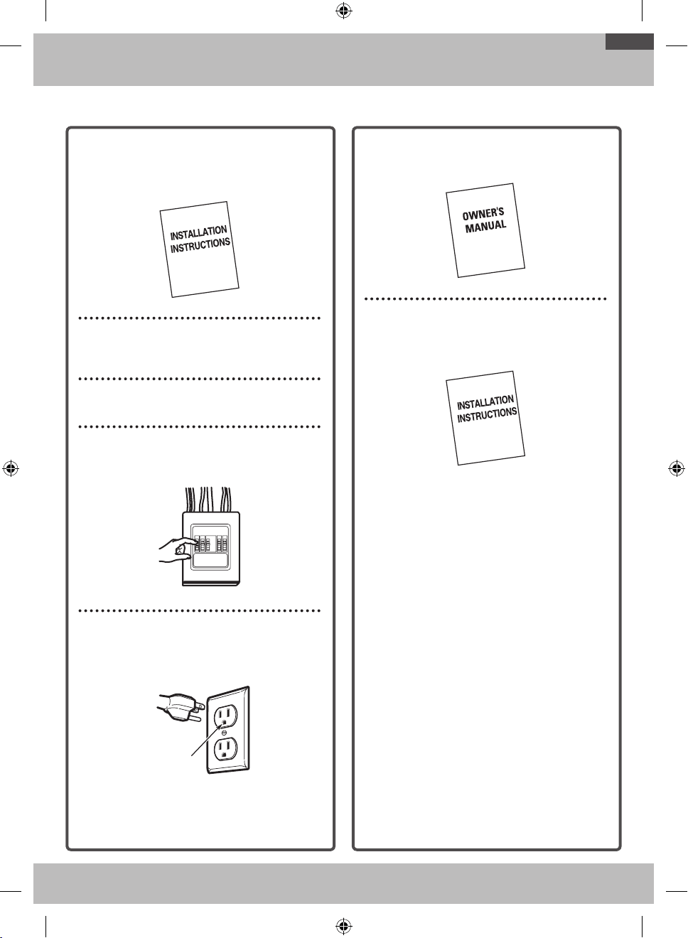
6. Read the Owner’s Manual.
7. KEEP INSTALLATION INSTRUCTIONS FOR
THE LOCAL INSPECTOR’S USE.
BEFORE YOU USE YOUR MICROWAVE
OTR_II_DE68-03587B-05_EN.indd 23 6/19/2019 3:56:14 PM

DE68-03587B-05
OTR_II_DE68-03587B-05_EN.indd 24 6/19/2019 3:56:15 PM
Consignes d'installation
Four micro-ondes à hotte intégrée
AVANT DE COMMENCER (Lisez attentivement l'intégralité des consignes.)
IMPORTANT
Conservez ces instructions pour pouvoir les remettre à l'inspecteur local en cas de passage.
IMPORTANT
Respectez tous les codes et règlements en vigueur.
• Remarque destinée à l'installateur - N'oubliez pas de laisser ces instructions à l'utilisateur.
• Remarque destinée à l'utilisateur - Conservez précieusement ces instructions afin de pouvoir vous y reporter ultérieurement.
• Niveau de compétences - L'installation de cet appareil nécessite des connaissances mécaniques et électriques de
base.
• Il incombe à l'installateur de poser correctement l'appareil.
• Tout dysfonctionnement imputable à une mauvaise installation n'est pas couvert par la garantie.
LISEZ ATTENTIVEMENT CE MANUEL. CONSERVEZ-LE PRÉCIEUSEMENT.
OTR_II_DE68-03587B-05_CFR.indd 1 6/19/2019 4:04:09 PM
2
Table des matières
Guide d'installation étape par étapeInformations générales
Consignes de sécurité importantes . . . . . . . . . . . 3
Exigences en matière de raccordement électrique . . 3
Système d'évacuation de la hotte . . . . . . . . . . . . 4
Dommages - Transport/Installation . . . . . . . . . . . 6
Pièces incluses avec l'appareil . . . . . . . . . . . . . 6
Outils nécessaires . . . . . . . . . . . . . . . . . . . . 7
Espace de montage . . . . . . . . . . . . . . . . . . . 7
1. Emplacement de la plaque de fixation . . . . . . . . 8
A. Retrait du four micro-ondes du carton/Retrait de la
plaque de fixation . . . . . . . . . . . . . . . . . . . 8
B. Détection des montants. . . . . . . . . . . . . . . .8
C. Détermination de l'emplacement de la plaque
murale sous le meuble . . . . . . . . . . . . . . . . 9
D. Alignement de la plaque murale . . . . . . . . . . 10
2. Types d'installation (A, B ou C) . . . . . . . . . . . 11
A. Système d'évacuation par le haut (conduit vertical) . . 12
A1. Fixation de la plaque murale . . . . . . . . . 12
A2. Utilisation du gabarit du meuble haut pour la
préparation du meuble haut . . . . . . . . . . 12
A3. Procédure d'installation de l'adaptateur
du système d'évacuation et contrôle de
fonctionnement du registre . . . . . . . . . . 13
A4. Montage du four micro-ondes. . . . . . . . . 13
A5. Réglage de l'adaptateur du système
d'évacuation . . . . . . . . . . . . . . . . . . 14
A6. Raccordement des conduits . . . . . . . . . 14
B. Circulation de l'air en circuit fermé (sans conduit
et sans évents). . . . . . . . . . . . . . . . . . . . 15
B1. Fixation de la plaque murale . . . . . . . . . 15
B2. Utilisation du gabarit du meuble haut pour la
préparation du meuble haut . . . . . . . . . . 15
B3. Adaptation du ventilateur du four micro-ondes
à la circulation en circuit fermé . . . . . . . . 16
B4. Montage du four micro-ondes. . . . . . . . . 17
B5. Installation du filtre à charbon. . . . . . . . . 18
C. Système d'évacuation par l'arrière
(conduit horizontal) . . . . . . . . . . . . . . . . . 19
C1. Préparation du mur du fond pour le système
d'évacuation par l'arrière . . . . . . . . . . . 19
C2. Fixation de la plaque murale . . . . . . . . . 20
C3. Utilisation du gabarit du meuble haut pour la
préparation du meuble haut . . . . . . . . . . 20
C4. Adaptation du ventilateur du four micro-ondes
au système d'évacuation par l'arrière. . . . . 20
C5. Montage du four micro-ondes. . . . . . . . . 22
Avant d’utiliser votre four micro-ondes . . . . . . . . 23
OTR_II_DE68-03587B-05_CFR.indd 2 6/19/2019 4:04:09 PM
3
Informations générales
CONSIGNES DE SÉCURITÉ IMPORTANTES
Cet appareil nécessite une prise tripolaire reliée à la terre.
L'installateur doit eectuer une vérification de la continuité de
la mise à la terre de la prise électrique avant de commencer
l'installation afin de s'assurer que la prise est correctement mise
à la terre. Si ce n'est pas le cas, ou si la prise ne répond pas
aux exigences indiquées en matière de raccordement électrique
(dans la section EXIGENCES EN MATIÈRE DE RACCORDEMENT
ÉLECTRIQUE), faites appel à un électricien qualifié pour corriger
les défaillances.
Insure proper
ground exists
before use
ATTENTION: pour votre
sécurité, retirez le fusible de
l'installation électrique ou
ouvrez le disjoncteur avant
de commencer l'installation
afin d'éviter tout risque
d'électrocution grave voire
mortelle.
ATTENTION: pour votre sécurité, la surface de fixation doit
être capable de supporter le poids du meuble, en plus des
63 à 85livres de l'appareil et des charges supplémentaires
pouvant aller jusqu'à 50livres, soit un poids total compris
entre 113 et 135livres.
ATTENTION: pour votre sécurité, cet appareil ne doit
pas être installé dans des meubles disposés en îlot ou en
péninsule. Il doit être fixé À LA FOIS à un meuble haut ET
à un mur.
REMARQUE: pour plus de facilité et de sécurité lors de
l'installation de l'appareil, deux personnes sont nécessaires.
IMPORTANT – LISEZ ATTENTIVEMENT CE MANUEL.
POUR VOTRE SÉCURITÉ, CET APPAREIL DOIT ÊTRE
CORRECTEMENT MIS À LA TERRE AFIN D'ÉVITER TOUT
RISQUE D'ÉLECTROCUTION GRAVE VOIRE MORTELLE.
Insure proper
ground exists
before use
Assurez-vous que le
four est correctement
mis à la terre avant
de l'utiliser.
Le cordon d'alimentation de
cet appareil est équipé d'une
prise tripolaire (mise à la
terre) correspondant à la prise
murale tripolaire standard
(mise à la terre) afin de réduire
le risque d'électrocution.
Faites vérifier la prise murale et le circuit par un électricien
qualifié afin de vous assurer que la prise est correctement
mise à la terre.
Lorsqu'une prise murale bipolaire standard est utilisée,
il est très important qu'elle soit remplacée par une prise
murale tripolaire correctement mise à la terre et installée
par un électricien qualifié.
NE COUPEZ, NE DÉFORMEZ NI NE RETIREZ JAMAIS LES
BROCHES DE LA PRISE DU CORDON D'ALIMENTATION.
N'UTILISEZ PAS DE RALLONGE.
EXIGENCES EN MATIÈRE
DE RACCORDEMENT
ÉLECTRIQUE
La valeur nominale de l'appareil est de 120volts CA, 60Hz, 13A
et 1,5kW. Cet appareil doit être relié à un circuit d'alimentation
doté de la tension et de la fréquence appropriées. La taille des
fils doit être conforme aux exigences du Code électrique national
ou du code local en vigueur pour la valeur nominale en kilowatts.
Le cordon d'alimentation et la fiche doivent être reliés à une prise
simple séparée reliée à la terre avec circuit de dérivation compris
entre 15 et 20A. La prise doit être placée dans le meuble situé au-
dessus du four micro-ondes. La prise et le circuit d'alimentation
doivent être installés par un électricien qualifié et conformément au
Code électrique national ou au code local en vigueur.
OTR_II_DE68-03587B-05_CFR.indd 3 6/19/2019 4:04:10 PM
4
Informations générales
REMARQUE: les deux prochaines pages ne vous concernent que si vous souhaitez utiliser un système d'évacuation de l'air vers
l'extérieur. Si vous souhaitez que la circulation de l'air se fasse en circuit fermé, passez à la page11.
SYSTÈME D'ÉVACUATION PAR LE HAUT (EXEMPLE UNIQUEMENT)
Le tableau suivant contient un exemple d'installation de conduits possible.
COMPOSANTS DU SYSTÈME
D'ÉVACUATION
LONGUEUR
ÉQUIVALENTE
x
NOMBRE
UTILISÉ
=
LONGUEUR
ÉQUIVALENTE
Chaperon de toit 24pi x (1) = 24pi
12pi Conduit droit
(diamètre 6")
12pi x (1) = 12pi
Adaptateur rectangulaire-
circulaire*
5pi x (1) = 5pi
Les longueurs équivalentes des composants du système d'évacuation
sont basées sur des essais réels et reflètent les exigences en matière de
performance de ventilation avec n'importe quel type de hotte.
Longueur totale = 41pi
* IMPORTANT: si un adaptateur rectangulaire-circulaire est utilisé, les coins inférieurs du registre devront être coupés à l'aide de cisailles afin de le
fixer et de permettre au registre de bouger librement.
SYSTÈME D'ÉVACUATION PAR L'ARRIÈRE (EXEMPLE UNIQUEMENT)
Le tableau suivant contient un exemple d'installation de conduits possible.
COMPOSANTS DU SYSTÈME
D'ÉVACUATION
LONGUEUR
ÉQUIVALENTE
x
NOMBRE
UTILISÉ
=
LONGUEUR
ÉQUIVALENTE
Chaperon mural 40pi x (1) = 40pi
3pi Conduit droit
(Rectangulaire de
3¼" x 10")
3pi x (1) = 3pi
Coude à 90° 10pi x (2) = 20pi
Les longueurs équivalentes des composants du système d'évacuation
sont basées sur des essais réels et reflètent les exigences en matière de
performance de ventilation avec n'importe quel type de hotte.
Longueur totale = 63pi
REMARQUE: pour l'évacuation par l'arrière, veillez à aligner l'évacuation sur l'espace situé entre les montants ou préparez le mur lors de sa
construction en ménageant un espace entre les montants du mur afin de disposer l'évacuation.
SYSTÈME D'ÉVACUATION DE LA HOTTE
OTR_II_DE68-03587B-05_CFR.indd 4 6/19/2019 4:04:11 PM

5
Informations générales
REMARQUE: si vous devez installer des conduits, notez que la
longueur totale du conduit rectangulaire de 3¼" x 10" ou du conduit
circulaire de 6" de diamètre ne doit pas dépasser 140pieds.
La ventilation extérieure nécessite un SYSTÈME D'ÉVACUATION DE
LA HOTTE. Veuillez lire attentivement ce qui suit.
REMARQUE: il est important que la ventilation soit installée selon
la trajectoire la plus directe et avec le moins de coudes possible.
Cela garantit une bonne ventilation et évite les obstructions. Vérifiez
également que les registres bougent librement et que rien
n'obstrue les conduits.
Raccordement de l'évacuation:
Le système d'évacuation de la hotte a été conçu pour s'adapter à
un conduit rectangulaire de 3¼" x 10".
Si un conduit circulaire est nécessaire, utilisez un adaptateur
rectangulaire-circulaire. N'utilisez pas de conduit d'un diamètre
inférieur à 6".
Longueur maximale du conduit:
afin de permettre à l'air de circuler, la longueur totale du conduit
rectangulaire de 3¼" x 10" ou du conduit circulaire de 6" de
diamètre ne doit pas dépasser 140pieds.
Les coudes, raccords, murs, chaperons de
toit, etc., représentent une résistance supplémentaire à la
circulation de l'air et sont équivalents à une partie de conduit droit
plus long que leur véritable taille. Lors du calcul de la longueur totale
du conduit, ajoutez les longueurs équivalentes de tous les raccords
et adaptateurs à la longueur de toutes les parties de conduit droit.
Le tableau suivant vous indique comment calculer la longueur
équivalente totale des conduits en utilisant la longueur équivalente
en pieds de quelques conduits types.
COMPOSANTS DU SYSTÈME
D'ÉVACUATION
LONGUEUR
ÉQUIVALENTE
x
NOMBRE
UTILISÉ
=
LONGUEUR
ÉQUIVALENTE
Adaptateur rectangulaire-
circulaire*
5pi x ( ) = pi
Chaperon mural 40pi x ( ) = pi
Coude à 90° 10pi x ( ) = pi
Coude à 45° 5pi x ( ) = pi
Coude à 90° 25pi x ( ) = pi
Coude à 45° 5pi x ( ) = pi
Chaperon de toit 24pi x ( ) = pi
Conduit droit circulaire de 6" ou
rectangulaire de 3¼" x 10"
1pi x ( ) = pi
Total des conduits = pi
* IMPORTANT: si un adaptateur rectangulaire-
circulaire est utilisé, les coins inférieurs du registre
devront être coupés à l'aide de cisailles afin de
le fixer et de permettre au registre de bouger
librement.
Les longueurs équivalentes des composants du
système d'évacuation sont basées sur des essais
réels et reflètent les exigences pour de bonnes
performances de ventilation avec n'importe quel
type de hotte.
OTR_II_DE68-03587B-05_CFR.indd 5 6/19/2019 4:04:11 PM

6
Informations générales
• Si l'appareil est endommagé lors du transport, retournez-le au magasin dans lequel il a été acheté afin qu'il soit réparé ou
remplacé.
• Si l'appareil est endommagé par l'utilisateur, sa réparation ou son remplacement lui incombe.
• Si l'appareil est endommagé par l'installateur (autre que l'utilisateur), un accord devra être trouvé entre l'utilisateur et
l'installateur en vue d'une réparation ou d'un remplacement.
DOMMAGES - TRANSPORT/INSTALLATION
MATÉRIEL
PIÈCE QUANTITÉ
Template
INSTALLATION
INSTRUCTIONS
Vis à bois
(¼" x 2")
1
Template
INSTALLATION
INSTRUCTIONS
Boulons à ailettes
(et écrous à oreilles)
(
3
/
16
" x 3")
2
Template
INSTALLATION
INSTRUCTIONS
Vis mécaniques
autocentreuses
(¼" - 28 x 3¼")
2
L'appareil est livré avec un sachet contenant le matériel d'installation.
Vérifiez que vous disposez de toutes ces pièces.
REMARQUE: certaines pièces supplémentaires sont incluses.
PIÈCES SUPPLÉMENTAIRES
PIÈCE QUANTITÉ
TOP CABINET TEMPLATE
REAR WALL TEMPLATE
Gabarit du meuble haut 1
TOP CABINET TEMPLATE
REAR WALL TEMPLATE
Gabarit du mur du fond 1
Consignes d'installation 1
Filtre à graisses emballé
séparément
2
Template
INSTALLATION
INSTRUCTIONS
Adaptateur du système
d'évacuation
1
PIÈCES INCLUSES AVEC L'APPAREIL
OTR_II_DE68-03587B-05_CFR.indd 6 6/19/2019 4:04:12 PM
7
Informations générales
Tournevis cruciforme
n°1 et n°2
Crayon Règle ou mètre à ruban et règle
plate
Équerre de charpentier (facultatif)
Cisailles (pour la coupe du
registre si nécessaire)
Ciseaux (pour la coupe du
gabarit si nécessaire)
Perceuse électrique avec mèches
de
3
/
16
", ½" et ⅝"
Cales ou morceaux de bois, pour
l'espacement du meuble haut si
nécessaire (utilisé pour l'installation de
meubles bas encastrés uniquement)
Gants Scie (scie sauteuse, scie-
cloche ou scie à guichet)
Détecteur de montant ou marteau
(facultatif)
Lunettes de protection
Niveau Ruban adhésif en toile et
ruban de masquage
OUTILS NÉCESSAIRES
16½"
30"
2"
30" minimum
Le fond du meuble
doit être situé à
au moins 30" de
la surface de cuisson.
Dosseret
Au moins 66" entre
le sol et le haut du
micro-ondes
REMARQUES:
• L'espace entre les meubles doit être de 30" et dégagé.
• Si l'espacement entre les meubles est supérieur à 30", un kit
de remplissage peut être utilisé pour combler l'espace entre le
four micro-ondes et les meubles. Le numéro du kit pour votre
modèle figure dans votre manuel d'utilisation.
• Ce four micro-ondes est conçu pour être installé au-dessus
d'une cuisinière de 36" de large.
• Si vous souhaitez utiliser un système de ventilation pour le four
micro-ondes avec évacuation vers l'extérieur, reportez-vous à la
partie Système d'évacuation de la hotte pour la préparation du
conduit d'évacuation.
• Lors de l'installation du four micro-ondes sous un meuble
plat et lisse, respectez les instructions figurant sur le
gabarit du meuble haut pour la distance d'isolement du
cordon d'alimentation.
ESPACE DE MONTAGE
OTR_II_DE68-03587B-05_CFR.indd 7 6/19/2019 4:04:15 PM
8
Guide d'installation étape par étape
1. EMPLACEMENT DE LA PLAQUE DE FIXATION
A. RETRAIT DU FOUR MICRO-ONDES
DU CARTON/RETRAIT DE LA
PLAQUE DE FIXATION
1. Retirez les consignes d'installation, l'adaptateur du
système d'évacuation, les filtres, le plateau en verre et
le petit sachet contenant le matériel. Ne retirez pas la
mousse de polystyrène protégeant l'avant du four.
2. Pliez les 4rabats du carton contre ses côtés. Retournez
avec précaution le four et le carton sur le dessus. Le four
doit reposer sur la mousse de polystyrène.
Styrofoam
Carton
Carton
Mousse de
polystyrène
3. Tirez le carton vers le haut pour en sortir le four.
4. Retirez et jetez les sacs en plastique de manière
appropriée.
Screws
Screws
Mounting Plate
Vis
Plaque de fixation
Vis
5. Retirez les 2vis de la plaque de fixation. Cette plaque
est utilisée comme gabarit du mur du fond et pour le
montage.
REMARQUE: vous devrez réutiliser les deux vis à leur
emplacement d'origine sur le châssis une fois la plaque de fixation
retirée.
B. DÉTECTION DES MONTANTS
Wall Studs
Center
Centre
Montants
1. Recherchez les montants en utilisant l'une des méthodes
suivantes:
A. Détecteur de montant: appareil magnétique qui
localise les clous.
OU
B. Utilisez un marteau pour taper légèrement la surface
de montage jusqu'à entendre un son sourd. Cela
indique l'emplacement d'un montant.
2. Une fois le ou les montants localisés, recherchez le
centre en sondant le mur à l'aide d'un clou afin de
détecter les bords du ou des montants. Puis tracez
un repère au centre des deux bords. Le centre des
montants adjacents doit être situé à 16" ou 24" de ce
repère.
3. Tracez un trait vertical à partir du centre des montants.
LE FOUR MICRO-ONDES DOIT ÊTRE FIXÉ SUR AU MOINS
UN MONTANT.
OTR_II_DE68-03587B-05_CFR.indd 8 6/19/2019 4:04:16 PM
9
Guide d'installation étape par étape
C. DÉTERMINATION DE L'EMPLACEMENT DE LA PLAQUE MURALE SOUS LE
MEUBLE
C
L
Position de la plaque: sous un meuble à fond plat.
Tracez un trait vertical sur le mur
du fond, au centre de l'espace de
30" de large.
Fixez le gabarit du fond au mur en
veillant à l'aligner sur le trait central et
à toucher le fond du meuble.
30" au minimum
16½"
C
L
Position de la plaque: sous un meuble encastré.
30" de la surface de cuisson
Tracez un trait vertical sur le mur du fond, au centre de l'espace de 30"
de large.
Fixez le gabarit du fond au mur en veillant à l'aligner sur le trait central et à
toucher le fond du cadre du meuble.
C
L
Plate position – beneath recessed bottom
cabinet with front overhang
Draw a line on the
back wall equal to the
depth of the front
overhang.
30" to Cooktop
Position de la plaque: sous un meuble encastré avec débord frontal.
30" de la surface
de cuisson
Sur le mur du fond, tracez
un trait égal à la profondeur
du débord frontal.
Si le meuble sur lequel vous souhaitez fixer l'appareil comporte des
ornements décoratifs, ces derniers risquent de gêner l'installation.
Retirez ces ornements pour assurer une installation et une mise à
niveau correctes du four.
IL EST TRÈS IMPORTANT QUE LE FOUR MICRO-ONDES SOIT
DE NIVEAU.
Utilisez un niveau pour vous assurer que le plancher du meuble est
bien à l'horizontale.
Si la structure est dotée d'un débord frontal (sans cadre arrière
ni latéral), installez la plaque de fixation sur le mur du fond en la
baissant de la longueur du débord. Le four micro-ondes sera ainsi
installé de niveau.
1. Mesurez la longueur du débord frontal.
2. Sur le mur du fond, tracez un trait horizontal situé à la
même distance du plancher du meuble que le débord.
3. Pour ce type d'installation avec débord uniquement, alignez
les pattes de fixation sur le trait horizontal en veillant à ne
pas toucher le plancher du meuble comme décrit dans
l'étapeD.
OTR_II_DE68-03587B-05_CFR.indd 9 6/19/2019 4:04:18 PM
10
Guide d'installation étape par étape
D. ALIGNEMENT DE LA PLAQUE MURALE
C
L
CAUTION: Wear gloves to avoid cutting
fingers on sharp edges.
Area E
Hole B
Hole A
Centerline
notches
Draw a Vertical Line
on Wall from Center
of Top Cabinet
Draw a Horizontal line on wall from
bottom of “Rear Wall Template”.
Horizontal Line
Horizontal Line
Tracez un trait horizontal sur le mur en partant du dessous du
«Gabarit du fond».
Sur le mur, tracez un trait
vertical en partant du centre du
meuble haut
Trait horizontal
Trait horizontal Zone E
Encoches sur
le trait central
Trou A
Trou B
ATTENTION: portez des gants car les bords sont très
tranchants.
1. Tracez un trait vertical sur le mur du fond, au centre
de l'espace de 30" de large.
2. Tracez un trait horizontal sur le mur juste en-dessous
du «Gabarit du fond».
3. Percez des trous de
5
/
8
" à trois emplacements
(trouA, trouB, trouC) en vue de la pose des
boulons à ailettes. Si l'emplacement du trou est le
même que celui d'un montant, percez un trou de
3
/
16
" en vue de la pose de la vis à bois. En d'autres
termes, l'emplacement des boulons à ailettes ne doit
pas être le même que celui des montants.
REMARQUE: N
E POSEZ PAS ENCORE LA
PLAQUE À CETTE ÉTAPE DU MONTAGE.
REMARQUE: les trousA, B et C se trouvent à l'intérieur de
la zoneE. Si A, B et C ne se trouvent pas dans un montant,
repérez au hasard un montant dans la zoneE et tracez un
cercle pour les aligner dessus. Il est important d'utiliser au
moins une vis à bois et de la fixer solidement dans un
montant afin que le montage ainsi formé supporte le poids
du four micro-ondes. Mettez la plaque de fixation de côté.
OTR_II_DE68-03587B-05_CFR.indd 10 6/19/2019 4:04:19 PM
11
Guide d'installation étape par étape
2. TYPES D'INSTALLATION (A, B OU C)
Ce four micro-ondes est compatible avec les trois systèmes de
ventilation suivants:
A. Système d'évacuation par le haut (Conduit Vertical)
B. Circulation de l'air en circuit fermé (Sans Conduit
Et Sans Évents)
C. Système d'évacuation par l'arrière (Conduit
Horizontal)
REMARQUE: ce micro-ondes est livré assemblé pour le système
d'évacuation par le haut (hormis les modèles sans évents).
Sélectionnez le système de ventilation adapté à votre installation et
reportez-vous à la section correspondante.
A. SYSTÈME D'ÉVACUATION PAR LE
HAUT (CONDUIT VERTICAL)
B. CIRCULATION DE L'AIR EN CIRCUIT
FERMÉ (SANS CONDUIT ET SANS
ÉVENTS)
Adaptor in Place
for Outside
Top Exhaust
Adaptateur en place
pour une évacuation
par le haut
Reportez-vous à la page12 Reportez-vous à la page15
C. SYSTÈME D'ÉVACUATION
PAR L'ARRIÈRE (CONDUIT
HORIZONTAL)
Reportez-vous à la page19
OTR_II_DE68-03587B-05_CFR.indd 11 6/19/2019 4:04:20 PM
12
Guide d'installation étape par étape
A. SYSTÈME D'ÉVACUATION PAR LE HAUT (CONDUIT VERTICAL)
PRÉSENTATION DE L'INSTALLATION
A1. Fixation de la plaque murale
A2. Préparation du meuble haut
A3. Montage du four micro-ondes
A4. Réglage de l'adaptateur du système d'évacuation
A5. Raccordement des conduits
A1. FIXATION DE LA PLAQUE MURALE
Fixez la plaque au mur à l'aide de boulons à ailettes. Au moins une
vis à bois est nécessaire pour fixer la plaque à un montant.
1. Retirez les ailettes des boulons.
2. Insérez les boulons dans la plaque de fixation via les
trous pour cloison sèche, puis engagez les ailettes sur
¾" sur chaque boulon.
Utilisation des boulons à ailettes:
Wall
Toggle Wings
Toggle
Bolt
Bolt End
Spacing for Toggles More
Than Wall Thickness
Mounting
Plate
Espacement des boulons à ailettes
supérieur à l'épaisseur du mur
Extrémité du
boulon
Plaque de
fixation
Boulon à
ailettes
Mur
Ailettes
3. Placez la plaque de fixation contre le mur et insérez les
ailettes dans les trous du mur pour fixer la plaque.
REMARQUE: avant de serrer les boulons à ailettes et la vis à
bois, assurez-vous que les pattes de la plaque de fixation sont
en contact avec le plancher du meuble lorsque vous poussez
celle-ci contre le mur (assurez-vous également que la plaque est
correctement centrée sur le plancher du meuble).
ATTENTION: veillez à ne pas vous pincer les doigts entre l'arrière
de la plaque de fixation et le mur.
4. Serrez tous les boulons. Retirez la plaque du mur pour
faciliter l'opération.
A2. UTILISATION DU GABARIT DU MEUBLE
HAUT POUR LA PRÉPARATION DU
MEUBLE HAUT
Vous devez à présent percer les trous des vis de fixation
supérieures; leur diamètre doit permettre le passage du cordon
d'alimentation et leur découpe la fixation de l'adaptateur du
système d'évacuation.
• Lisez les instructions figurant sur le GABARIT DU
MEUBLE HAUT.
• Collez-le sous le plancher du meuble haut.
• Percez les trous en respectant les instructions figurant sur
le GABARIT DU MEUBLE HAUT.
ATTENTION: portez des lunettes de sécurité pendant cette
dernière opération.
OTR_II_DE68-03587B-05_CFR.indd 12 6/19/2019 4:04:21 PM
13
Guide d'installation étape par étape
A3. PROCÉDURE D'INSTALLATION
DE L'ADAPTATEUR DU SYSTÈME
D'ÉVACUATION ET CONTRÔLE DE
FONCTIONNEMENT DU REGISTRE
Plaque du ventilateur
Registre
Adaptateur du système d'évacuation
Crochets de retenue
Arrière du four
micro-ondes
• Lisez les instructions figurant sur le GABARIT DU
MEUBLE HAUT.
• Collez-le sous le plancher du meuble haut.
• Percez les trous en respectant les instructions figurant sur
le GABARIT DU MEUBLE HAUT.
ATTENTION: portez des lunettes de sécurité pendant cette
dernière opération.
A4. MONTAGE DU FOUR MICRO-ONDES
POUR PLUS DE FACILITÉ ET DE SÉCURITÉ LORS DE
L'INSTALLATION DE L'APPAREIL, DEUX PERSONNES SONT
NÉCESSAIRES.
IMPORTANT: évitez de saisir ou d'utiliser la poignée
pendant l'installation.
REMARQUE: si votre meuble est en métal, placez la rondelle
en nylon autour du trou du cordon d'alimentation afin d'éviter de
couper ce dernier.
REMARQUE: nous vous recommandons d'utiliser des cales si
le meuble est doté d'un débord avant en dessous du fond du
meuble.
IMPORTANT: si vous n'utilisez pas de cales, l'habillage du
meuble risquerait d'être endommagé suite à un serrage trop
important des vis.
REMARQUE: lors du montage du four, faites passer le cordon
d'alimentation dans le trou pratiqué dans le plancher du meuble
haut. Tendez le câble au cours des étapes1 à3. Veillez en outre à
ne pas le coincer ou tirer dessus.
1. Soulevez le micro-ondes,
inclinez-le vers l'avant et
faites correspondre les
encoches situées à l'arrière
et en bas avec les quatre
pattes inférieures de la
plaque de fixation.
2. Remontez le four et
plaquez-le contre
le plancher du
meuble
.
3. Insérez une vis autocentreuse dans le trou central du
meuble haut. Fixez temporairement le four en faisant
eectuer à la vis d'au moins deux tours complet
après l'engagement des filets. (Elle sera complètement
serrée ultérieurement.) Veillez à garder le cordon
d'alimentation tendu. Attention à ne pas coincer le
cordon, en particulier au moment où vous collez le
four contre le plancher du meuble.
OTR_II_DE68-03587B-05_CFR.indd 13 6/19/2019 4:04:22 PM
14
Guide d'installation étape par étape
Cabinet Front
Filler Block
Microwave Oven Top
Self-Aligning Screw
Equivalent to
Depth of
Cabinet Recess
Cabinet Bottom Shelf
Équivalent à
l'enfoncement du
meuble
Fond du meuble
Haut du four micro-ondes
Avant du meuble
Cale
Vis autocentreuse
4. Fixez le four micro-ondes sur le meuble haut.
5. Insérez 2vis autocentreuses dans
les trous extérieurs du meuble haut.
Tournez chaque vis de deux tours.
6. Serrez la vis centrale
complètement.
7. Serrez les deux vis extérieures dans la partie supérieure
du four micro-ondes. (Tout en serrant les vis, maintenez le
four contre le mur et le meuble haut.)
8. Installez le filtre à graisses. Reportez-vous au manuel
d'utilisation fourni avec le micro-ondes.
A5. RÉGLAGE DE L'ADAPTATEUR DU
SYSTÈME D'ÉVACUATION
Ouvrez le meuble haut et réglez l'adaptateur du système
d'évacuation afin de le relier au conduit de la cuisine.
Registre
Pour un réglage côté-côté,
faites glisser l'adaptateur
du système d'évacuation
autant que nécessaire.
Arrière du four
micro-ondes
A6. RACCORDEMENT DES CONDUITS
House Duct
Conduit de la cuisine
1. Tirez le conduit de la cuisine vers le bas pour le relier à
l'adaptateur du système d'évacuation.
2. Scellez les joints du conduit du système d'évacuation à
l'aide d'un ruban adhésif en toile.
OTR_II_DE68-03587B-05_CFR.indd 14 6/19/2019 4:04:23 PM

15
Guide d'installation étape par étape
B. CIRCULATION DE L'AIR EN CIRCUIT FERMÉ (SANS CONDUIT ET SANS ÉVENTS)
PRÉSENTATION DE L'INSTALLATION
B1. Fixation de la plaque murale
B2. Préparation du meuble haut
B3. Réglage du ventilateur
B4. Montage du four micro-ondes
B5. Installation du filtre à charbon
B1. FIXATION DE LA PLAQUE MURALE
Fixez la plaque au mur à l'aide de boulons à ailettes. Au moins une
vis à bois est nécessaire pour fixer la plaque à un montant.
1. Retirez les ailettes des boulons.
2. Insérez les boulons dans la plaque de fixation via les
trous pour cloison sèche, puis engagez les ailettes sur
¾" sur chaque boulon.
Utilisation des boulons à ailettes:
Wall
Toggle Wings
Toggle
Bolt
Bolt End
Spacing for Toggles More
Than Wall Thickness
Mounting
Plate
Espacement des boulons à ailettes
supérieur à l'épaisseur du mur
Extrémité du
boulon
Plaque de
fixation
Boulon à
ailettes
Mur
Ailettes
3. Placez la plaque de fixation contre le mur et insérez les
ailettes dans les trous du mur pour fixer la plaque.
REMARQUE: avant de serrer les boulons à ailettes et la vis à
bois, assurez-vous que les pattes de la plaque de fixation sont
en contact avec le plancher du meuble lorsque vous poussez
celle-ci contre le mur (assurez-vous également que la plaque est
correctement centrée sur le plancher du meuble).
ATTENTION: veillez à ne pas vous pincer les doigts entre l'arrière
de la plaque de fixation et le mur.
4. Serrez tous les boulons. Retirez la plaque du mur pour
faciliter l'opération.
B2. UTILISATION DU GABARIT DU MEUBLE
HAUT POUR LA PRÉPARATION DU
MEUBLE HAUT
Vous devez percer des trous pour les vis de fixation supérieures et
un trou de diamètre susamment important pour y faire passer le
cordon d'alimentation.
• Lisez les instructions figurant sur le GABARIT DU
MEUBLE HAUT.
• Collez-le sous le plancher du meuble haut.
• Percez les trous en respectant les instructions figurant sur
le GABARIT DU MEUBLE HAUT.
ATTENTION: portez des lunettes de sécurité pendant cette
dernière opération.
OTR_II_DE68-03587B-05_CFR.indd 15 6/19/2019 4:04:25 PM
16
Guide d'installation étape par étape
B3. ADAPTATION DU VENTILATEUR
DU FOUR MICRO-ONDES À LA
CIRCULATION EN CIRCUIT FERMÉ
1. Retirez et conservez la vis qui fixe la plaque du ventilateur au
micro-ondes.
2. Soulevez la plaque du ventilateur.
Arrière du four
micro-ondes
Vis de
retenue du
ventilateur
REMARQUE: l'adaptateur du système d'évacuation avec registre
n'est pas nécessaire sur les modèles avec système de circulation
en circuit fermé. Vous pouvez toutefois le conserver en vue d'une
utilisation ultérieure éventuelle.
3. Retirez le ventilateur avec précaution. Les câbles sortent
susamment pour vous permettre de le régler.
ATTENTION: ne touchez pas les ailettes du ventilateur, car
vous risqueriez de les fendre ou de les casser. Tenez fermement
l'habillage extérieur lorsque vous retirez ou remettez en place le
ventilateur.
4. Tournez le ventilateur de 90° afin que les ouvertures des
ailettes soient dirigées vers l'avant du micro-ondes.
Avant rotation
Après rotation
5. Remettez le ventilateur dans son logement.
ATTENTION: ne tirez pas sur les câbles du ventilateur. Assurez-
vous que les câbles n'ont pas été coincés au moment de la remise
en place.
6. Retirez le couvercle métallique du ventilateur à l'arrière du
micro-ondes en le glissant vers le haut.
7. Fermez la porte de la ventilation. Glissez la protection de
la ventilation sur le dessus de l'ouverture de la porte de la
ventilation.
8. Fixez la ventilation sur le micro-ondes à l'aide des vis de
fixation de la ventilation de l'étape1.
Arrière du four
à micro-ondes
Vis de
fixation de la
ventilation
Vis de fixation de la
ventilation
OTR_II_DE68-03587B-05_CFR.indd 16 6/19/2019 4:04:27 PM
17
Guide d'installation étape par étape
B4. MONTAGE DU FOUR MICRO-ONDES
POUR PLUS DE FACILITÉ ET DE SÉCURITÉ LORS DE
L'INSTALLATION DE L'APPAREIL, DEUX PERSONNES SONT
NÉCESSAIRES.
IMPORTANT: évitez de saisir ou d'utiliser la poignée
pendant l'installation.
REMARQUE: si votre meuble est en métal, placez la rondelle
en nylon autour du trou du cordon d'alimentation afin d'éviter de
couper ce dernier.
REMARQUE: nous vous recommandons d'utiliser des cales si
le meuble est doté d'un débord avant en dessous du fond du
meuble.
IMPORTANT: si vous n'utilisez pas de cales, l'habillage du
meuble risquerait d'être endommagé suite à un serrage trop
important des vis.
REMARQUE: lors du montage du four, faites passer le cordon
d'alimentation dans le trou pratiqué dans le plancher du meuble
haut. Tendez le câble au cours des étapes1 à3. Veillez en outre à
ne pas le coincer ou tirer dessus.
1. Soulevez le micro-ondes,
inclinez-le vers l'avant et
faites correspondre les
encoches situées à l'arrière
et en bas avec les quatre
pattes inférieures de la
plaque de fixation.
2. Remontez le four et
plaquez-le contre le
plancher du meuble
.
3. Insérez une vis autocentreuse dans le trou central du
meuble haut. Fixez temporairement le four en faisant
eectuer à la vis d'au moins deux tours complet
après l'engagement des filets. (Elle sera complètement
serrée ultérieurement.) Veillez à garder le cordon
d'alimentation tendu. Attention à ne pas coincer le
cordon, en particulier au moment où vous collez le
four contre le plancher du meuble.
Cabinet Front
Filler Block
Microwave Oven Top
Self-Aligning Screw
Equivalent to
Depth of
Cabinet Recess
Cabinet Bottom Shelf
Équivalent à
l'enfoncement du
meuble
Fond du meuble
Haut du four micro-ondes
Avant du meuble
Cale
Vis autocentreuse
4. Fixez le four micro-ondes sur le meuble haut.
5. Insérez 2vis autocentreuses dans
les trous extérieurs du meuble haut.
Tournez chaque vis de deux tours.
6. Serrez la vis centrale
complètement.
7. Serrez les deux vis extérieures dans la partie supérieure
du four micro-ondes. (Tout en serrant les vis, maintenez le
four contre le mur et le meuble haut.)
8. Installez le filtre à graisses. Reportez-vous au manuel
d'utilisation fourni avec le micro-ondes.
OTR_II_DE68-03587B-05_CFR.indd 17 6/19/2019 4:04:28 PM
18
Guide d'installation étape par étape
B5. INSTALLATION DU FILTRE À CHARBON
1. Retirez les vis situées sur le dessus de la grille à l'aide
d'un tournevis cruciformen°1.
2. Ouvrez la porte.
3. Retirez la grille.
• Poussez sur la gauche puis tirez vers vous.
Filtre à charbon
4. I
nstallez le filtre à charbon. Lorsqu'il est correctement installé,
l
e grillage métallique du filtre doit être visible depuis l'
a
vant.
5. Remettez la grille et les vis en place.
6. Fermez la porte.
Insérez côté grillage dirigé vers le haut
OTR_II_DE68-03587B-05_CFR.indd 18 6/19/2019 4:04:28 PM
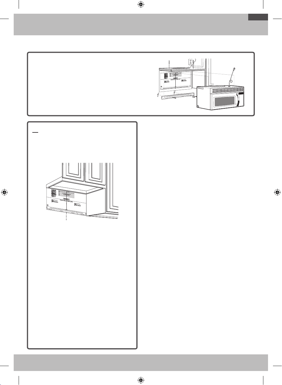
19
Guide d'installation étape par étape
C. SYSTÈME D'ÉVACUATION PAR L'ARRIÈRE (CONDUIT HORIZONTAL)
PRÉSENTATION DE L'INSTALLATION
C1. Préparation du mur du fond
C2. Fixation de la plaque murale
C3. Préparation du meuble haut
C4. Réglage du ventilateur
C5. Montage du four micro-ondes
C1. PRÉPARATION DU MUR DU FOND
POUR LE SYSTÈME D'ÉVACUATION
PAR L'ARRIÈRE
Vous devez pratiquer une ouverture dans le mur du fond pour
installer le système d'évacuation.
C
L
• Lisez les instructions figurant sur le GABARIT DU MUR
DU FOND.
• Collez le gabarit sur le mur du fond.
• Pratiquez l'ouverture en respectant les instructions
figurant sur le GABARIT DU MUR DU FOND.
OTR_II_DE68-03587B-05_CFR.indd 19 6/19/2019 4:04:29 PM
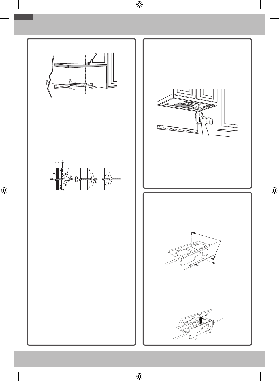
20
Guide d'installation étape par étape
C2. FIXATION DE LA PLAQUE MURALE
Fixez la plaque au mur à l'aide de boulons à ailettes. Au moins une
vis à bois est nécessaire pour fixer la plaque à un montant.
1. Retirez les ailettes des boulons.
2. Insérez les boulons dans la plaque de fixation via les
trous pour cloison sèche, puis engagez les ailettes sur
¾" sur chaque boulon.
Utilisation des boulons à ailettes:
Wall
Toggle Wings
Toggle
Bolt
Bolt End
Spacing for Toggles More
Than Wall Thickness
Mounting
Plate
Espacement des boulons à ailettes
supérieur à l'épaisseur du mur
Extrémité du
boulon
Plaque de
fixation
Boulon à
ailettes
Mur
Ailettes
3. Placez la plaque de fixation contre le mur et insérez les
ailettes dans les trous du mur pour fixer la plaque.
REMARQUE: avant de serrer les boulons à ailettes et la vis à
bois, assurez-vous que les pattes de la plaque de fixation sont
en contact avec le plancher du meuble lorsque vous poussez
celle-ci contre le mur (assurez-vous également que la plaque est
correctement centrée sur le plancher du meuble).
ATTENTION: veillez à ne pas vous pincer les doigts entre l'arrière
de la plaque de fixation et le mur.
4. Serrez tous les boulons. Retirez la plaque du mur pour
faciliter l'opération.
C3. UTILISATION DU GABARIT DU MEUBLE
HAUT POUR LA PRÉPARATION DU
MEUBLE HAUT
Vous devez à présent percer les trous des vis de fixation
supérieures; leur diamètre doit permettre le passage du cordon
d'alimentation et leur découpe la fixation de l'adaptateur du
système d'évacuation.
• Lisez les instructions figurant sur le GABARIT DU
MEUBLE HAUT.
• Collez-le sous le plancher du meuble haut.
• Percez les trous en respectant les instructions figurant sur
le GABARIT DU MEUBLE HAUT.
ATTENTION: portez des lunettes de sécurité pendant cette
dernière opération.
C4. ADAPTATION DU VENTILATEUR DU
FOUR MICRO-ONDES AU SYSTÈME
D'ÉVACUATION PAR L'ARRIÈRE
1. Retirez et conservez les vis fixant la plaque et le moteur
du ventilateur au four micro-ondes.
Arrière du four
micro-ondes
Vis de
retenue du
ventilateur
2. Ouvrez la plaque du ventilateur située à l'arrière du
micro-ondes, en la soulevant. Retirez le protecteur du
ventilateur situé à l'arrière du micro-ondes en le faisant
glisser vers le haut, et conservez-le. Retirez le cache
métallique du ventilateur situé à l'arrière du micro-ondes
en le faisant glisser vers le haut, et conservez-le.
OTR_II_DE68-03587B-05_CFR.indd 20 6/19/2019 4:04:29 PM
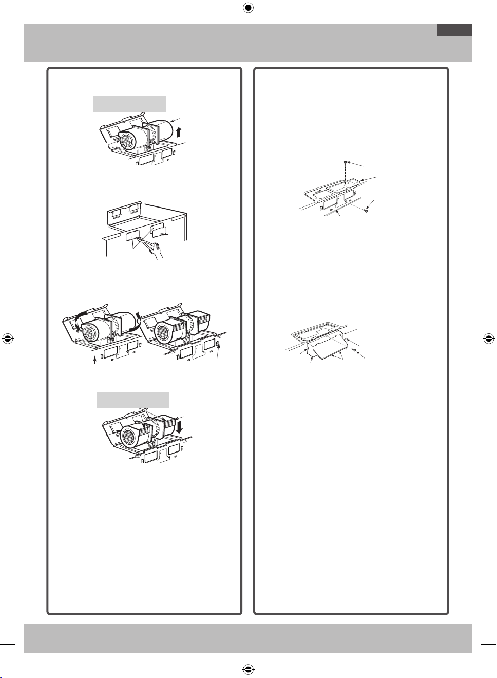
21
Guide d'installation étape par étape
3. Retirez le ventilateur avec précaution. Les câbles sortent
susamment pour vous permettre de le régler.
AVANT: ouvertures des ailettes du
ventilateur dirigées vers l'avant
Extrémité B
Extrémité A
4. Retirez les parties«A» à l'aide de cisailles à tôles ou de
pinces. (Sur Certains Modèles)
Parties A
5. Faites pivoter le ventilateur de 180° dans le sens inverse
des aiguilles d'une montre.
Avant la rotation Après la rotation
Arrière du micro-ondes
Arrière du micro-ondes
6. Remettez le ventilateur dans son logement.
APRÈS: ouvertures des ailettes du
ventilateur dirigées vers l'arrière
Extrémité B
Extrémité A
ATTENTION: ne tirez pas sur les câbles du ventilateur.
Assurez-vous que les câbles n'ont pas été coincés au
moment de la remise en place.
REMARQUE: les ouvertures du système d'évacuation du
ventilateur doivent correspondre aux ouvertures situées à
l'arrière du four micro-ondes.
7. Remettez la plaque du ventilateur et la vis en place, au
même emplacement que précédemment.
8. Fermez la plaque du ventilateur. Faites glisser le protecteur
du ventilateur par-dessus l'ouverture de la plaque du
ventilateur. Fixez le ventilateur sur le four micro-ondes à
l'aide des vis de retenue du ventilateur retirées à l'étape1,
à l'exception de la vis de retenue supérieure du moteur
ventilateur.
Vis de retenue
du ventilateur
Protecteur du
ventilateur
Vis de retenue
du ventilateur
Arrière du four
micro-ondes
9. Faites glisser l'adaptateur du système d'évacuation
sur l'arrière du four micro-ondes, en le fixant dans les
languettes de verrouillage inférieures. Assurez-vous que la
charnière du registre est située dans la partie supérieure
et que le registre bouge librement. Réinstallez la vis
supérieure du moteur du ventilateur dans l'adaptateur et
la plaque du ventilateur, ainsi qu'à l'arrière du four micro-
ondes.
Guide
Guide
Adaptateur
Languettes de
verrouillage
(non présentées)
Vis de retenue de la plaque
du moteur du ventilateur
Arrière du four
micro-ondes
OTR_II_DE68-03587B-05_CFR.indd 21 6/19/2019 4:04:31 PM
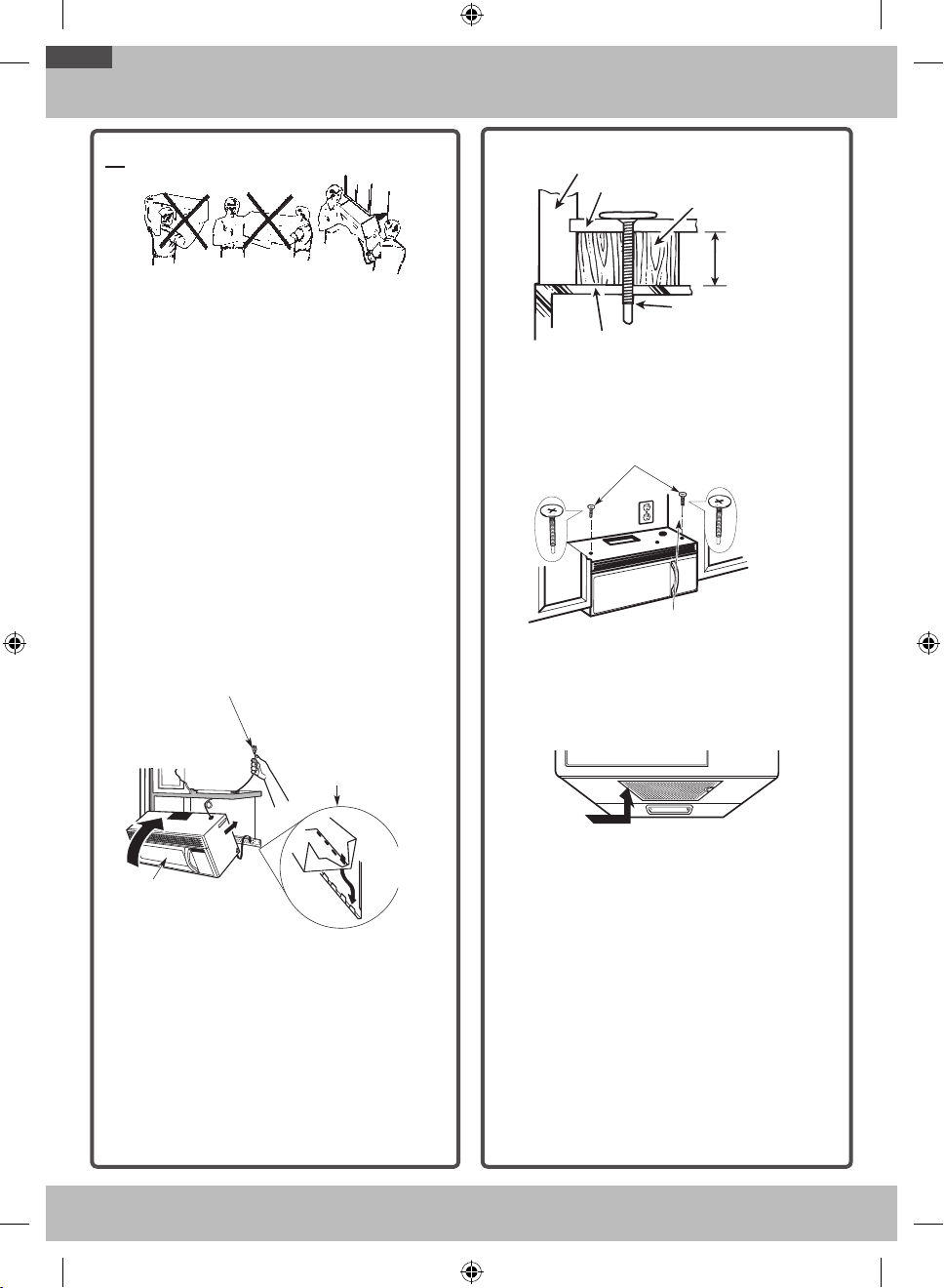
22
Guide d'installation étape par étape
C5. MONTAGE DU FOUR MICRO-ONDES
POUR PLUS DE FACILITÉ ET DE SÉCURITÉ LORS DE
L'INSTALLATION DE L'APPAREIL, DEUX PERSONNES SONT
NÉCESSAIRES.
IMPORTANT: évitez de saisir ou d'utiliser la poignée pendant
l'installation.
REMARQUE: si votre meuble est en métal, placez la rondelle
en nylon autour du trou du cordon d'alimentation afin d'éviter de
couper ce dernier.
REMARQUE: nous vous recommandons d'utiliser des cales si le
meuble est doté d'un débord avant en dessous du fond du meuble.
IMPORTANT: si vous n'utilisez pas de cales, l'habillage du
meuble risquerait d'être endommagé suite à un serrage trop
important des vis.
REMARQUE: lors du montage du four, faites passer le cordon
d'alimentation dans le trou pratiqué dans le plancher du meuble
haut. Tendez le câble au cours des étapes1 à3. Veillez en outre à
ne pas le coincer ou tirer dessus.
1. Soulevez le micro-ondes,
inclinez-le vers l'avant et
faites correspondre les
encoches situées à l'arrière
et en bas avec les quatre
pattes inférieures de la
plaque de fixation.
2. Remontez le four et
plaquez-le contre le
plancher du meuble
.
3. Insérez une vis autocentreuse dans le trou central du
meuble haut. Fixez temporairement le four en faisant
eectuer à la vis d'au moins deux tours complet
après l'engagement des filets. (Elle sera complètement
serrée ultérieurement.) Veillez à garder le cordon
d'alimentation tendu. Attention à ne pas coincer le
cordon, en particulier au moment où vous collez le
four contre le plancher du meuble.
Cabinet Front
Filler Block
Microwave Oven Top
Self-Aligning Screw
Equivalent to
Depth of
Cabinet Recess
Cabinet Bottom Shelf
Équivalent à
l'enfoncement du
meuble
Fond du meuble
Haut du four micro-ondes
Avant du meuble
Cale
Vis autocentreuse
4. Fixez le four micro-ondes sur le meuble haut.
5. Insérez 2vis autocentreuses dans
les trous extérieurs du meuble haut.
Tournez chaque vis de deux tours.
6. Serrez la vis centrale
complètement.
7. Serrez les deux vis extérieures dans la partie supérieure
du four micro-ondes. (Tout en serrant les vis, maintenez le
four contre le mur et le meuble haut.)
8. Installez le filtre à graisses. Reportez-vous au manuel
d'utilisation fourni avec le micro-ondes.
OTR_II_DE68-03587B-05_CFR.indd 22 6/19/2019 4:04:31 PM
23
Avant d'utiliser votre four micro-ondes
1. Assurez-vous que le four micro-ondes a été installé
conformément aux instructions.
2. Retirez tout élément d'emballage du four micro-
ondes.
3. Installez le plateau tournant et l'anneau de guidage
dans le four.
4. Remplacez le fusible ou remettez le disjoncteur sous
tension.
Insure proper
ground exists
before use
5. Branchez le cordon d'alimentation sur une prise
dédiée de 20A.
Insure proper
ground exists
before use
Assurez-vous
que le four est
correctement mis
à la terre avant de
l'utiliser.
6. Lisez le manuel d'utilisation.
7. CONSERVEZ LES INSTRUCTIONS POUR POUVOIR
LES REMETTRE À L'INSPECTEUR LOCAL EN CAS
DE PASSAGE.
AVANT D’UTILISER VOTRE FOUR MICRO-ONDES
OTR_II_DE68-03587B-05_CFR.indd 23 6/19/2019 4:04:31 PM

DE68-03587B-05
OTR_II_DE68-03587B-05_CFR.indd 24 6/19/2019 4:04:32 PM