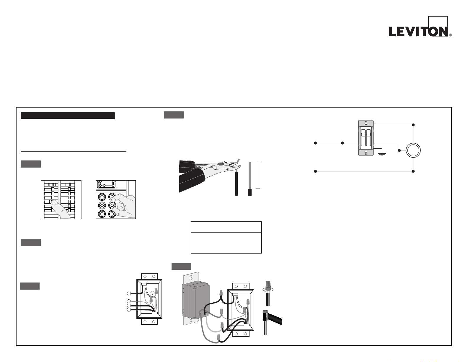
Single-Pole Wiring Application:
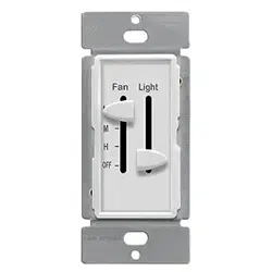
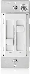
Dual Quiet Fan/Light Control
Single Pole (One Location)
Cat. No. 66DF – LED/CFL 150W, Incandescent 300W, 1.5A Fan
120VAC, 60Hz
INSTALLATION INSTRUCTIONS
Step 3
Step 4
Removing existing switch: Remove existing
wallplate and switch mounting screws. Carefully pull switch
from wall box. DO NOT remove wires attached to the
switch at this time.
Step 2
Tools needed to install your Dimmer
Slotted/Philips Screwdriver Electrical Tape Pliers
Pencil Cutters Ruler
WARNING: To avoid fire, shock, or death; TURN OFF
POWER at circuit breaker or fuse and test that power is off
before wiring!
ONOFF
ONOFF
ONOFF
ONOFF
ONOFF
ONOFF
ONOFFONOFF
ONOFF
ONOFF
ONOFF
ONOFF
Step 1
INSTALLING YOUR FAN/LIGHT CONTROL
Insert wires
straight
then twist
clockwise
Electrical Tape
Step 5
Connect wires per WIRING DIAGRAM as follows:
Screw wire connector on clockwise making sure no bare conductors
show below the wire connectors. Secure each connector with electrical
tape.
• Green fan/light control Ground lead to Green or bare copper wire in
wall box.
• Black fan/light control lead to Line (Hot) wire in wall box.
• Yellow fan/light control lead to Load (Light) wire in wall box.
• Red fan/light control lead to Load (Fan) wire in wall box.
Wiring Diagram - Single Location Control Application
Hot (Black)
Black
Neutral (White)
Red (Fan)
White
Fan/Light
Line
120V AC/CA, 60 Hz
Green Ground
Yellow (Light)
WIRE CONNECTOR / # OF COND.
COMBINATION CHART
1- #12 w/ 1 to 3 #14, #16 or #18
2- #12 w/ 1 or 2 #16 or #18
1- #14 w/ 1 to 4 #16 or #18
2- #14 w/ 1 to 3 #16 or #18
For non-standard wiring applications, refer to
Wire Connector Size Chart
WARNINGS:
• TO AVOID FIRE, SHOCK, OR DEATH; TURN OFF POWER at circuit breaker or fuse and test that power is off
before wiring or servicing fixture!
• To be installed and/or used in accordance with appropriate electrical codes and regulations.
• If you are unsure about any part of these instructions, consult an electrician.
CAUTIONS:
• To avoid overheating and possible damage to this device and other equipment, DO NOT use dimmer to control a
receptacle, a motor- or a transformer-operated appliance, or any other lighting sources than those specified. Use
only the fan control to control a fan.
• Use this device with copper or copper clad wire only.
CAUTIONS:
• Use with compatible dimmable LED, CFL bulbs, incandescent or 120V halogen fixtures only.
For a complete list of compatible LED and CFL bulbs refer to www.leviton.com.
• When multiple bulbs are used with one dimmer DO NOT mix bulb types. All bulbs shall be either LED; CFL or
incandescent. Using the same make/model of each bulb will enhance dimmer performance.
• This control is to be used with ceiling fans that are rated 120VAC, total load 1.5 amperes maximum
• For use on ceiling paddle fans with split-capacitor or shaded pole motors only. Please refer to manufacturer's
instructions or rating label on the motor to confirm type. Use with any other types of motors or equipment may cause
overheating and/or damage to the motors or equipment.
Single Pole
1. Line (Hot)
2. Neutral
3. Ground
4. Load
(Light)
5. Load (Fan)
2
4
5
3
1
Preparing and connecting wires:
Strip gage
Cut
(if necessary)
5/8"
• Make sure that the ends of the wires from the wall box are straight
(cut if necessary).
• Remove 5/8" (1.6 cm) of insulation from each wire in the wall box
(shown).
•
For Single-Pole Application, go to Step 5
DI-000-066DF-02A
Identifying your
wiring application
(most common)
NOTE: If the wiring in the
wall box does not resemble
any of these configurations,
consult an elecrician
Black
Green
Neutral
Yellow
Ground
Red
SureSlide
TM
decora
®

Setting Minimum Light Level (Programming mode)
1. Locate the “Trim Adjustment” dial on the bottom of the dimmer.
2. Slide dimmer control lever to the lowest dimming level/setting.
3. Rotate the dial clockwise to increase the minimum light level. Rotate
counter-clockwise to decrease the minimum light level.
OPERATION
• Lights Flickering
- Lamp has a bad connection.
- Wires not secured firmly with wire connectors.
• CFL and LED flickers at low end of dimming range
- Increase the low end of the dimming range.
Operation Section - setting minimum light level.
• CFL or LED bulb flickers throughout dimming range
- Please refer to recommended dimmable LED bulbs and CFL bulbs
at www.leviton.com.
• Light or Fan does not turn ON
- Circuit breaker or fuse has tripped.
- Lamp is burned out.
- Lamp Neutral connection is not wired.
TROUBLESHOOTING
LIMITED 5 YEAR WARRANTY AND EXCLUSIONS
Leviton warrants to the original consumer purchaser and not for the benefit of anyone else that this product at the time of its sale by Leviton is free of defects in materials and workmanship under normal and proper use for five years from the purchase date. Leviton’s
only obligation is to correct such defects by repair or replacement, at its option, if within such five year period the product is returned prepaid, with proof of purchase date, and a description of the problem to Leviton Mfg. Co., Inc. 201 North Service Road, Melville,
N.Y. 11747. This warranty excludes and there is disclaimed liability for labor for removal of this product or reinstallation. This warranty is void if this product is installed improperly or in an improper environment, overloaded, misused, opened, abused, or altered in any
manner, or is not used under normal operating conditions or not in accordance with any labels or instructions. There are no other or implied warranties of any kind, including merchantability and fitness for a particular purpose, but if any implied warranty is
required by the applicable jurisdiction, the duration of any such implied warranty, including merchantability and fitness for a particular purpose, is limited to five years. Leviton is not liable for incidental, indirect, special, or consequential damages, including without
limitation, damage to, or loss of use of, any equipment, lost sales or profits or delay or failure to perform this warranty obligation. The remedies provided herein are the exclusive remedies under this warranty, whether based on contract, tort or otherwise.
For Technical Assistance Call: 1-800-824-3005 (U.S.A. Only)
www.leviton.com
Sureslide is a trademark of Leviton Manufacturing Co., Inc.
registered in the United States and Canada.
Light Operation
ON: Slide control lever up to turn lights
ON at desired level of light.
OFF: Slide control lever all the way down
until it clicks to turn lights OFF.
BRIGHTEN: Raise slider control lever.
DIM: Lower slider control lever.
The slider on the left side of the face is used to control
the LIGHT. The slider on the right side of the face is
used to control the FAN.
Fan Operation
OFF: Slide control lever down to the bottom position to turn the fan OFF.
ON (Low): Slide control lever up one position from the bottom to turn the
fan ON at the lowest speed.
ON (Medium): Slide control lever up to the second position from the
bottom to turn the fan ON to the medium speed.
ON (High): Slide control lever up to the top position to turn the fan ON to
the highest speed.
Device Mounting:
TURN OFF POWER AT CIRCUIT BREAKER OR FUSE.
Step 7
Installation may now be completed by
carefully positioning all wires to provide
room in wall box for dimmer. Mount
dimmer into box with mounting screws
supplied. Attach Decora
®
wallplate.
Testing your dimmer prior to mounting in wall
box:
• Restore power at circuit breaker or
fuse.
• Carefully hold device as shown,
slide dimmer control lever to highest
position. Lights should turn on to
the brightest level.
If lights do not turn ON, refer to
the TROUBLESHOOTING section.
Step 6a
Testing your fan control prior to mounting in
wall box:
• Restore power at circuit breaker or
fuse.
• Carefully hold device as shown,
slide fan control lever to highest
position. Fan should turn ON to the
highest speed.
If fan does not turn ON, refer to
the TROUBLESHOOTING section.
Step 6b
Restore Power: Restore power at circuit breaker or fuse.
Installation is complete.
Step 8
© 2019 Leviton Mfg. Co., Inc.
FOR CANADA ONLY
For warranty information and/or product returns, residents of Canada should
contact Leviton in writing at Leviton Manufacturing of Canada Ltd to the
attention of the Quality Assurance Department, 165 Hymus Blvd, Pointe-
Claire (Quebec), Canada H9R 1E9 or by telephone at 1 800 405-5320.
Trim
Adjustment
Dial
DI-000-066DF-02A