Loading ...
Loading ...
Loading ...
2.3 Battery Connection
2.3.1 Battery Power Cable Connection
Note: for lead acid battery, the recommended charge current is 0.2C( C to battery capacity)
1. Please follow below steps to implement battery connection:
2. Assemble battery ring terminal based on recommended battery cable and terminal size.
3. Connect all battery packs as units requires. It's suggested to connect at least 200Ah capacity battery
for SNA5000 WPV.
4. Insert the ring terminal of battery cable flatly into battery connector of inverter and make sure the bolts
are tightened with torque of 2 ~3Nm. Make sure polarity of the battery is correctly connected and ring
terminals are tightly screwed to the battery terminals.
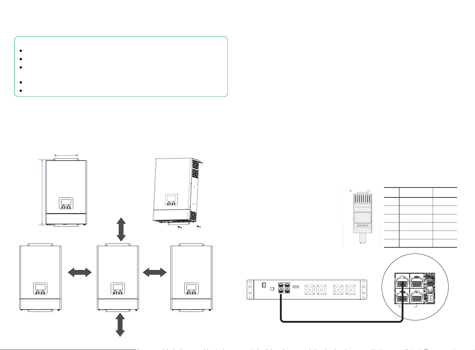
2.3.2 Lithium Battery Connection
If choosing lithium battery for SNA5000 WPV, please make sure the battery BMS is compatible with
Luxpower inverter. Please check the compatible list in the Luxpower website.
Please follow below steps to implement lithium battery connection:
1. Connect power cable between inverter and battery
2. Connect the CAN or RS485 communication cable between inverter and battery. If you do not get
the communication cable from inverter manufacturer or battery manufacturer, please make the cable
according to the PIN definition
3. Lithium battery configuration, in order to
communicate with battery BMS, you should
set the battery type to “Li-ion” in Program
“03” by LCD and choose the right battery
brand (for details, please check the LCD
setting chapter), users can also choose the
battery type and brand by monitor system.
Pin
1 2
3
4
5
6 7 8
Pin
1
2
3
4
RS 485B
CANL
CANH
5/6
RS 485 port CAN port
RS 485A
7/8
- - -
- - -
- - -
- - -
- - -
- - -
- - -
- - -
07
08
1
2
3 4
5
6
MPPT485
NTC
Parallel
Battery Pack
Inverter
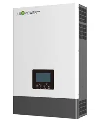
2.2 Mounting the Unit
Consider the following points before selecting where to install:
Mount on a solid surface
Do not mount the inverter on flammable construction materials.
For proper air circulation to dissipate heat, allow a clearance of approx. 20 cm to the side and approx.
50 cm above and below the unit.
The ambient temperature should be between 0°C and 55°C to ensure optimal operation.
The recommended installation position is to be adhered to the wall vertically.
180 mm
519 mm
Step1. Use the wall-mounting bracket as the template to mark the position of the 4 holes, then drill 8 mm
holes and make sure the depth of the holes is deeper than 50mm.
Step2. Install the expansion tubes into the holes and tight them, then use the expansion screws (packaged
together with the expansion tubes) to install and fix the wall-mounting bracket on the wall.
Step3. Install the inverter on the wall-mounting bracket and lock the inverter using the security screws.
200mm 200mm
500mm
500mm
Steps to mounting the unit
Notice:
Loading ...
Loading ...
Loading ...