Loading ...
Loading ...
Loading ...
1 HEAT / 1 COOL -
No Auxiliary Heat
R
24 VAC Power
O/B Changeover Valve [Note 2]
Y Compressor Call
G Fan Call
C 24 VAC Transformer Common [Note 1]
HEAT PUMP THERMOSTATS
(for use on heat pump systems only)
2 HEAT / 1 COOL - With Auxiliary Heat
R
24 VAC Power
O/B Changeover Valve [Note 2]
L Optional System Fault Monitor
AUX Auxiliary Heat Relay (2nd Stage Heating)
Y Compressor Call (1st Stage Heating/Cooling)
E Emergency Heat Call
G Fan Call
C 24 VAC Transformer Common [Note 1]
NOTES
[1] Wiring to the C terminal is required only for thermostat power.
[2] O (Cool active) or B (Heat active) must match the zone panel
configuration (section 4).
Thermostat Wiring
3.2
7
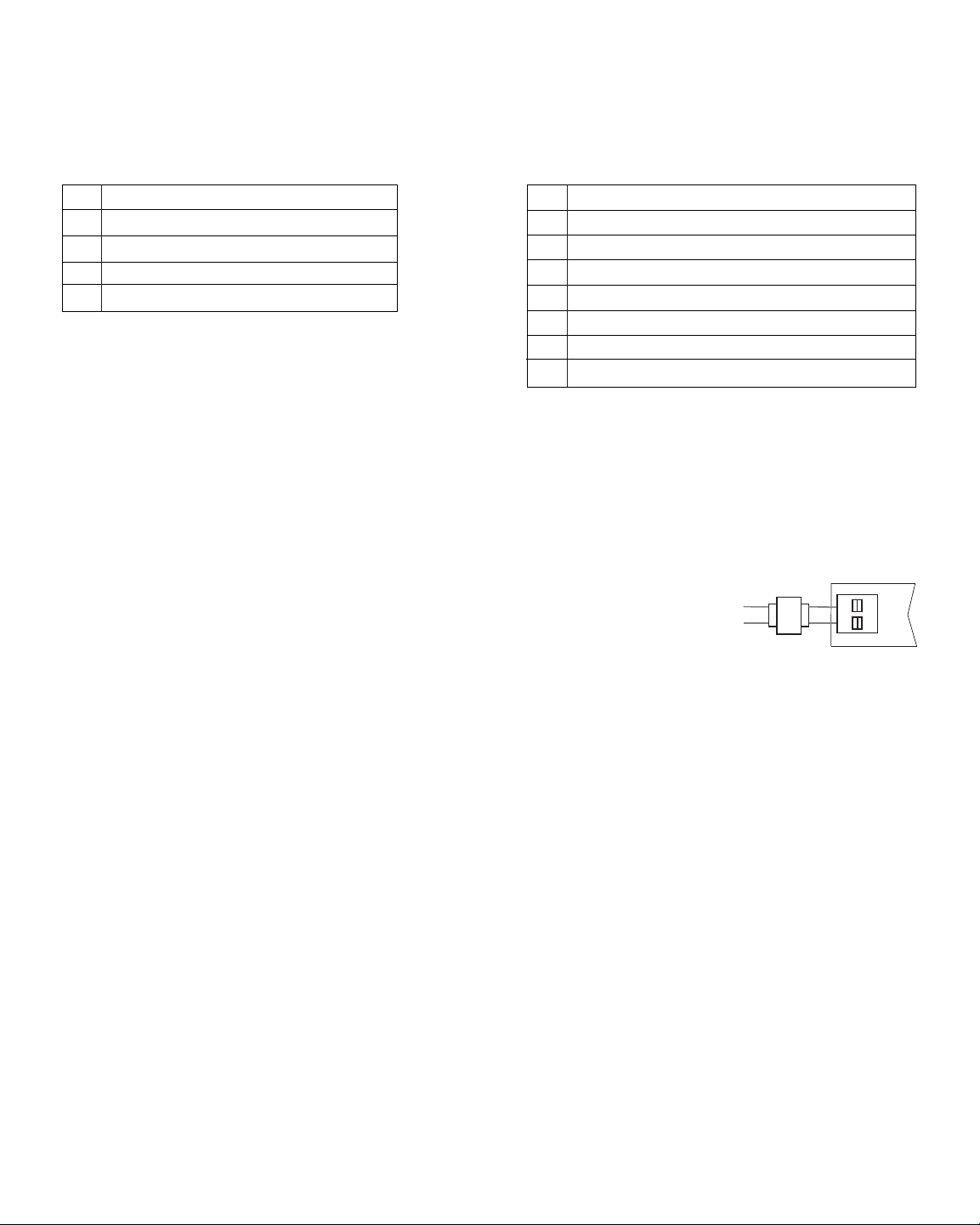
Transformer Wiring
3.3
Install the transformer using the instructions provided by the manufacturer. Size the
transformer to the damper requirements. The zone panel has built-in, self-resetting
fuses. The maximum damper power per panel is 100 VA at 24 VAC. Connect the
transformer to the zone panel as shown.
NOTE: Additional dampers or dampers with a higher current draw will require the
use of a separate slave relay.
ALWAYS PROVIDE DISCONNECT AND OVERLOAD PROTECTION AS REQUIRED
24V
24C
CC
HOT
Dedicated
Zoning Transformer
Zone
Panel
Loading ...
Loading ...
Loading ...