Loading ...
Loading ...
Loading ...
Version 3/15 - Page 17
ELECTRICAL CONNECTION
WARNING:TO REDUCE THE RISK OF FIRE,
ELECTRIC SHOCK, OR INJURY TO
PERSONS, OBSERVE THE FOLLOWING:
All electrical work should be performed by a
qualied electrician in strict accordance with
national regulations and local safety
regulations. Installation, repairs and other work
by unqualied persons could be
dangerous. Ensure that power to the appliance
is off while installation or repair work
is performed.
This unit may only be used in connection with
Faber internal or remote blowers
WARNING THIS APPLIANCE MUST BE
GROUNDED
Check Operation
1. Push and hold the button on the top of the
downdraft vent for a few seconds. The
retractable section of the downdraft vent
will rise. The blower will start immediately if
the blower control knob is set to an “on”
position.
2. Slide the control slider on the side of the
vent to check the speed of the blower. If the
blower does not operate:
- Check that the lters are pressed in as far as
they will go.
- Check that circuit breaker has not tripped or
a household fuse has blown.
- Check the downdraft vent fuse located under
the power board.
4. Connect the vent system to 6" (IBDD600
blower) or 10" (remote blowers) round vent
collar plate. Position the vent to avoid wall
studs and oor joists. Complete all vent work.
Use clamps to seal all joints. Vertical vent for
wall-mounted installations should pitch down
slightly toward the vent to allow moisture to
run outside.
5. Install the cooktop according to
manufacturer’s instructions. Check that rear of
cooktop overlaps the edge of the retractable
downdraft vent by ³⁄₈" (9.5 mm). See
Countertop Cutout Dimensions.
NOTE: To get the most efcient use from your
new retractable downdraft vent, read the “Vent
System Use” section.
- If you have not yet done so, remove
the cover of the terminal box.
- Install a suitable UL listed cable clamp or
conduit tting at the cable knock-out.
- Pass the power supply cable through
the knock-out of the housing into the
terminal box.
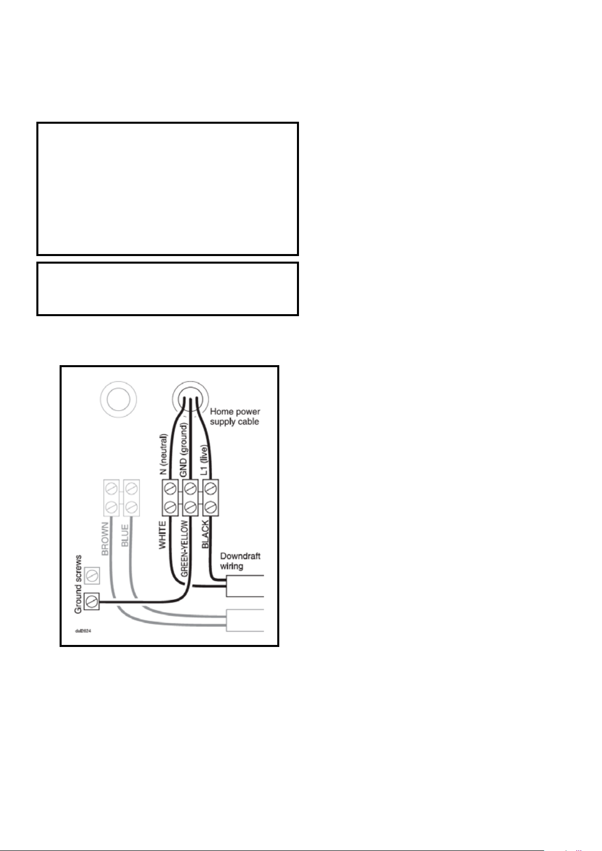
Important
The ventilation system must be hard
wired as follows:
- Connect black (L1 / live) cable from the
home power into the right terminal spot
- Connect the green ground wire from the
home power into the middle spot
- Connect the white (neutral) wire from the
home power into the left terminal spot
- Ensure that the terminal screws are tightly
holding all wires into place
Loading ...
Loading ...
Loading ...