The equipment can be started with a lithium-ion battery. The battery pack is completely sealed and maintenance free.
Battery Charge Level Indicator
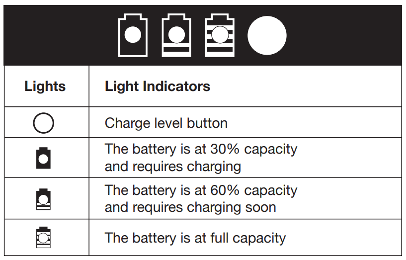
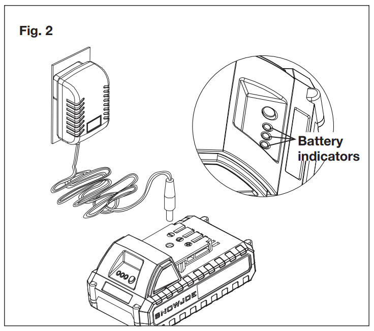
The battery pack is equipped with a push button for checking the charge level. Simply press the push button to read off the battery charge level from the LEDs of the battery indicator:
All 3 level monitoring LEDs are lit: Battery charge level is high.
2 level monitoring LEDs are lit: Battery charge level is decreasing. Charge the battery as soon as possible.
1 level monitoring LED is lit: Battery is flat. Charge the battery IMMEDIATELY. Otherwise the battery’s service life will be greatly shortened.
NOTE: If the charge level button does not appear to be working, connect to the charger and charge as needed.
NOTE: Immediately after using the battery pack, the charge level button may display a lower charge than it will if checked a few minutes later. The battery cells “recover” some of their charge after resting.
Charger Operation
WARNING! Charge only 24V iON+ lithium-ion battery pack with its compatible 24V iON+ lithium-ion charger. Other types of batteries may cause personal injury and damage.
To reduce the risk of electric shock, do not allow water to flow into the charger's AC/DC plug.
When to Charge the iON+ 24VBAT-LTE Lithium-iON Battery
NOTE: The iON+ 24VBAT-LTE lithium-iON battery pack does not develop a "memory" when charged after only a partial discharge. Therefore, it is not necessary to run down the battery pack before inserting the charger plug.
Use the battery indicator lights to determine when to charge your iON+ 24VBAT-LTE lithium-iON battery pack.
You can "top-off" your battery pack's charge before starting a big job or after a long day of use.
Charging the Battery
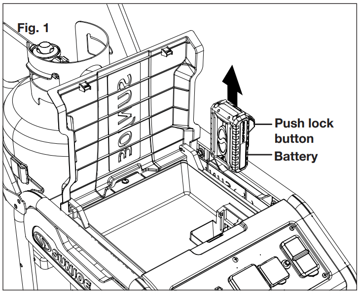
1. Press the push lock buttons on the battery to pull it out of the equipment.
2. Check that the mains voltage is the same as that marked on the rating plate of the battery charger. Then, plug the charger adapter into an appropriate AC power outlet. Connect the charger plug into the charge socket of the battery to start charging.
3. The battery will take approximately 5 hours to charge. The battery indicator LEDs will twinkle and illuminate one by one during the charging process. Unplug the charger immediately when the 3 LEDs are all illuminated.
CAUTION! FIRE HAZARD. When disconnecting the charger from the battery, be sure to unplug the charger from the outlet first, then disconnect the charger from the battery.
WARNING! This charger does not automatically turn off when the battery is fully charged. Please take care not to leave the battery plugged into the charger. Switch off or unplug the charger at the mains when charging is complete.
4. Timely recharging of the battery will help prolong the battery's life.
IMPORTANT! Never allow the battery pack to become fully discharged as this will cause irreversible damage to the battery.
Operation
DANGER! Carbon Monoxide. Using a generator indoors CAN KILL YOU IN MINUTES.
Generator exhaust contains high levels of carbon monoxide (CO), a poisonous gas you cannot see or smell. If you can smell the generator exhaust, you are breathing CO. But even if you cannot smell the exhaust, you could be breathing CO.
Never use a generator inside homes, garages, crawlspaces, or other partly enclosed areas. Deadly levels of carbon monoxide can build up in these areas. Using a fan or opening windows and doors does NOT supply enough fresh air.
ONLY use a generator outdoors and far away from open windows, doors, and vents. These openings can pull in generator exhaust.
Even when you use a generator correctly, CO may leak into the home. ALWAYS use a battery-powered or battery-backup CO alarm in the home. If you start to feel sick, dizzy, or weak after the generator has been running, move to fresh air RIGHT AWAY. See a doctor. You could have carbon monoxide poisoning.
WARNING! This generator will be used ONLY with cord and plug connected equipment, National Electric Code does not require that the unit be grounded. However, other methods of using the generator may require grounding to reduce the risk of shock or electrocution. Consult a qualified electrician, electrical inspector, or local agency having jurisdiction for local codes or ordinances to find out if grounding is needed in your situation before using the generator.
WARNING! Do not allow familiarity with this product to make you careless. Remember that a careless fraction of a second is sufficient to inflict serious injury.
WARNING! Do not use any attachments or accessories not recommended by the manufacturer of this product. The use of attachments or accessories not recommended can result in serious personal injury.
This generator is designed to supply electrical power for operating compatible electrical lighting, appliances, tools, and motor loads.
Before Operating the Unit
Only use OUTSIDE and at least 20 feet away from windows, doors, and vents. Your specific home and/ or wind conditions may require additional distance.
NEVER use inside a home or garage, EVEN IF doors and windows are open.
Always position the generator on a flat firm surface.
NOTE: There may be General or State Occupational Safety and Health Administration (OSHA) regulations, local codes or ordinances that apply to the intended use of the generator. Please consult a qualified electrician, electrical inspector, or the local agency having jurisdiction before using the appliance.
Grounding the Generator
WARNING! If this generator will be used only with cord and plug-connected equipment, National Electric Code does not require that the unit be grounded. However, other methods of using the generator may require grounding to reduce the risk of shock or electrocution. Consult a qualified electrician, electrical inspector, or local agency having jurisdiction for local codes or ordinances to find out if grounding is needed in your situation before using the generator.
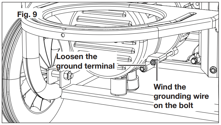
When grounding is required, the ground terminal on the frame is used to connect the generator to a suitable ground source. The ground path should be made with at least #12 size wire. Loosen the ground terminal. Wind the wire on the terminal insuring a metal to metal connection, and tighten the terminal fully. Connect the other end of the wire securely to a suitable ground source that is in contact with the soil for a minimum distance of 8 ft.
The National Electric Code contains several practical ways in which to establish a good ground source. If a steel or iron rod is used, it should be at least 5/8 in. diameter, and if a nonferrous rod is used, it should be at least 1/2 in. diameter and be listed as material for grounding. If a rock bottom is encountered before reaching a depth of 8 ft., drive the ground rod in at an angle of up to 45°. If the rock bottom is again encountered, the rod can be buried in a trench that is at least 30 in. deep. In all cases, the upper end of the grounding rod should either be flush with (or below) the ground or must be otherwise protected from physical damage.
All electrical tools and appliances operated from this generator must be properly grounded by use of a third wire or be "Double Insulated". It's recommended to
Use electrical devices with 3-prong grounded plugs.
Use an extension cord intended for outdoor use with a 3-pole receptacle and a 3-prong plug at opposite ends to ensure continuity of the ground protection from the generator to the appliance.
Checking/Adding Lubricant/Oil
WARNING! Attempting to start the engine before it has been properly filled with lubricant will result in equipment failure.
Engine lubricant has a major influence on engine performance and service life. Always use a 4-stroke motor lubricant (oil) that meets or exceeds the requirements for API service classification SJ, SF, 10W-30 or 10W-40. Non-detergent or 2-stroke engine lubricants will damage the engine and should not be used.
This engine comes with a feature that will shut off the engine when a specific lubricant level is not maintained. The engine will not restart until an appropriate lubricant level is reached.
Follow the instructions below to check and add lubricant.
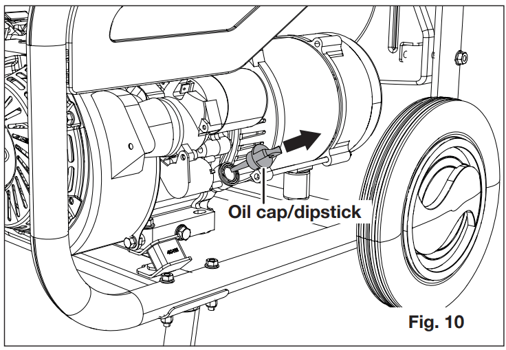
1. Unscrew the oil cap/dipstick and remove.
2. Wipe dipstick clean and re-seat in hole; do not rethread. Remove dipstick again and check lubricant level. Lubricant level should fall between the L mark and H mark on the dipstick.
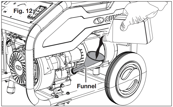
3. If the lubricant (oil) level is low, add engine lubricant using the equipped funnel. Make sure the generator is placed on a stable and level surface when adding lubricant. Fill with oil until the fluid level rises to the upper portion of the dipstick.
4. Replace and secure the oil cap/dipstick.
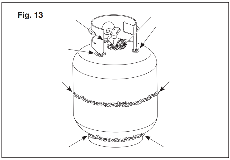
Testing the Propane Cylinder
Before connecting the cylinder with the generator, make sure to test the cylinder for leakage. Follow the instructions below.
1. Make sure the propane cylinder is disconnected from the propane hose and regulator.
2. Make leakage solution by mixing 1 part liquid dish soap and 3 parts water.
3. Using a clean paint brush, brush the soapy solution over areas indicated by arrows.
4. If bubbles show up, there is a leak. Do not use or move the propane cylinder. Contact a gas supplier or the fire department!
5. If you see, smell, or hear the hiss of escaping gas from the propane cylinder:
Move away from propane cylinder.
Do not attempt to correct the problem yourself.
Call your local fire department.
Connecting/Installing the Propane Cylinder
Propane is highly flammable and may ignite unexpectedly when mixed with air. The propane cylinder used with this generator must meet the following requirements:
Constructed and marked in accordance with all specifications required by related law and regulations.
Measurements: 12 in. diameter x 18 in. tall with 20 lb. maximum capacity, or 12 in. diameter x 23 in. tall with 30 lb. maximum capacity.
Cylinder valve must have Type 1 connection device compatible with the connector for the generator.
Cylinder must be equipped with safety relief valve.
Cylinder valve must have UL listed Overfill Protection Device (OPD). This OPD safety feature is identified by a unique triangular handwheel. Use only propane cylinders with this type of valve.
Arranged for vapor withdrawal and include collar to protect propane cylinder valve. Always keep propane cylinder in upright position during use, transport, or storage.
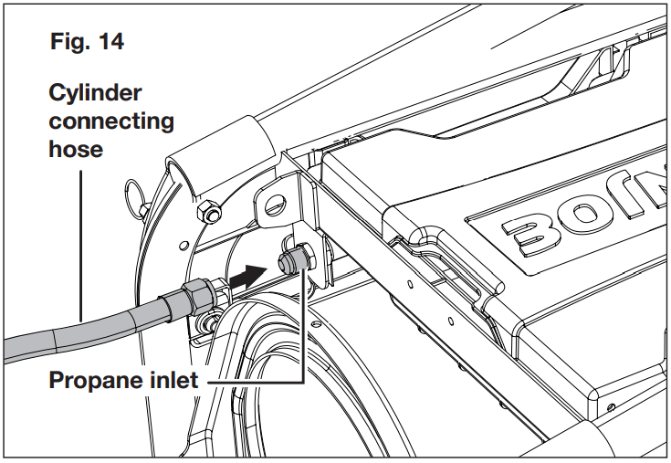
To install and connect the propane cylinder with the generator, follow the instructions below.
1. Pull the handle lock pin ring and restore the handle to the storage position. Remove the cap on the propane inlet, and connect the propane connecting hose to the propane inlet. Screw the locking nut on the hose clockwise tightly with a wrench for a secure connection.
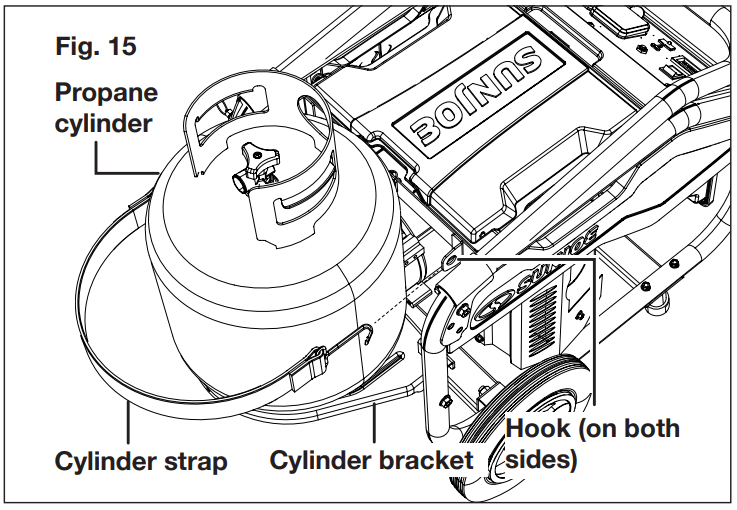
2. Lower the cylinder bracket completely. Place a propane cylinder (not included) into the bracket, making sure the bottom of the cylinder is placed securely in the opening in the bracket. To secure the cylinder, place the cylinder strap around the cylinder and connect to the hook on the generator frame as shown.
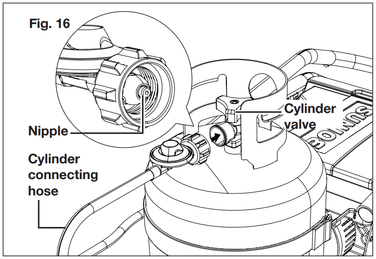
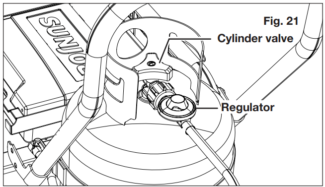
3. Make sure the cylinder valve on the propane cylinder is turned clockwise to its full off position. Hold the propane connecting hose firmly and insert the nipple into the cylinder valve.
NOTE: Nipple must be centered in the cylinder valve.
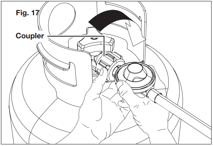
4. Holding the coupler and hose as shown, turn the coupler clockwise and tighten by hand, taking care not to crossthread the connection. Do not use tools.
NOTE: The hose will seal in the cylinder valve resulting in some resistance. An additional one-half to three quarters turn is required to complete the connection. If you cannot complete the connection, disconnect and repeat the above two steps. If you still cannot complete the connection, DO NOT use this propane connection hose!
5. Inspect valve connections port and propane connection hose. Look for any damage or debris. Remove any debris. Inspect hose for damage. Never attempt to use damaged or plugged equipment. See your local propane dealer for repairs.
Leakage Test
All connections of this generator have been checked at the factory for leakage. However, in transportation and handling some connections may have loosened. It's recommended to run the leakage test every time before using.
WARNING!
Do not use an open flame to check for leakage.
Do not smoke during testing.
Do not test indoors.
A leak check must be performed whenever the cylinder is replaced.
NOTE: Use only the propane connecting hose supplied with this generator. Replace it with those specified by the manufacturer only.
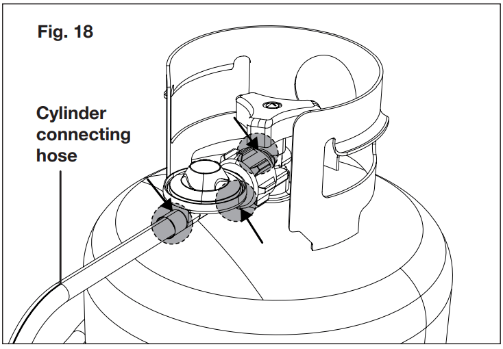
1. Make leakage solution by mixing 1 part liquid dish soap and 3 parts water.
2. With the cylinder connected to the hose, spoon or brush several drops (or use squirt bottle) of the solution onto the connections along the hose, regulator and cylinder.
3. Turn on the cylinder. Inspect the connections and look for bubbles. If no bubbles appear, the connection is safe. If bubbles appear, there is leakage. Loosen and re-tighten this connection.
Control Panel
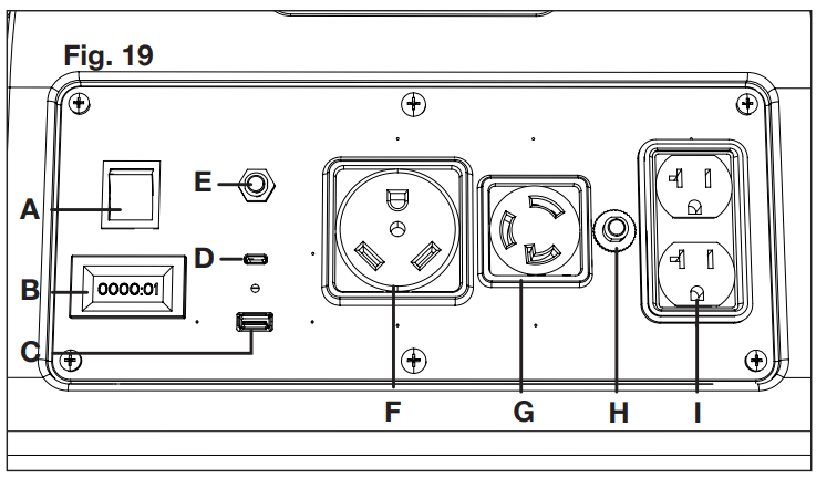
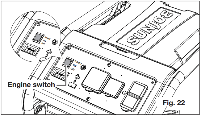
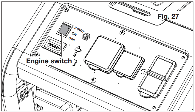
A. Engine switch – Use the engine switch to start the generator.
B. Digital display – The display shows the amount of time the generator has run since being started. It will automatically reset when reached the Max. number it can show.
When a cumulative run time of 20 hours has been reached, replace the engine lubrication. After the first time of replacing lubricant, replace the lubricant every 100 hours. When a cumulative time of 50 hours is reached, clean the air filter. When a cumulative time of 100 hours is reached, clean the spark plug.
C. 5 Volt 2 Amp USB receptacle.
D. Multi Volts (5V, 9V, 15V and 20V) USB-Type C receptacle.
E. Main circuit breaker button – Main circuit breaker is designed to protect the generator against overload. The breaker will trip and the button will stick out if overload happens. Press the main circuit beaker button to reset the circuit.
F. 120 Volt AC 30 Amp RV receptacle.
G. 120 Volt AC 30 Amp twist lock receptacle.
H. AC circuit breaker button – AC circuit breaker is designed to protect the AC circuit against overload. The breaker will trip and the button will stick out if overload happens. Press the AC circuit breaker button to reset the circuit.
I. 120 Volt AC 20 Amp duplex receptacle.
Start the Generator
Electric start
Follow the instruction below to start the generator.
1. On a level surface with the engine off, check the lubricant level before each use of the generator.
NOTE: If location of generator is not level, the unit may not start or may shut down during operation.
2. Make sure there's no load plugged into the generator.
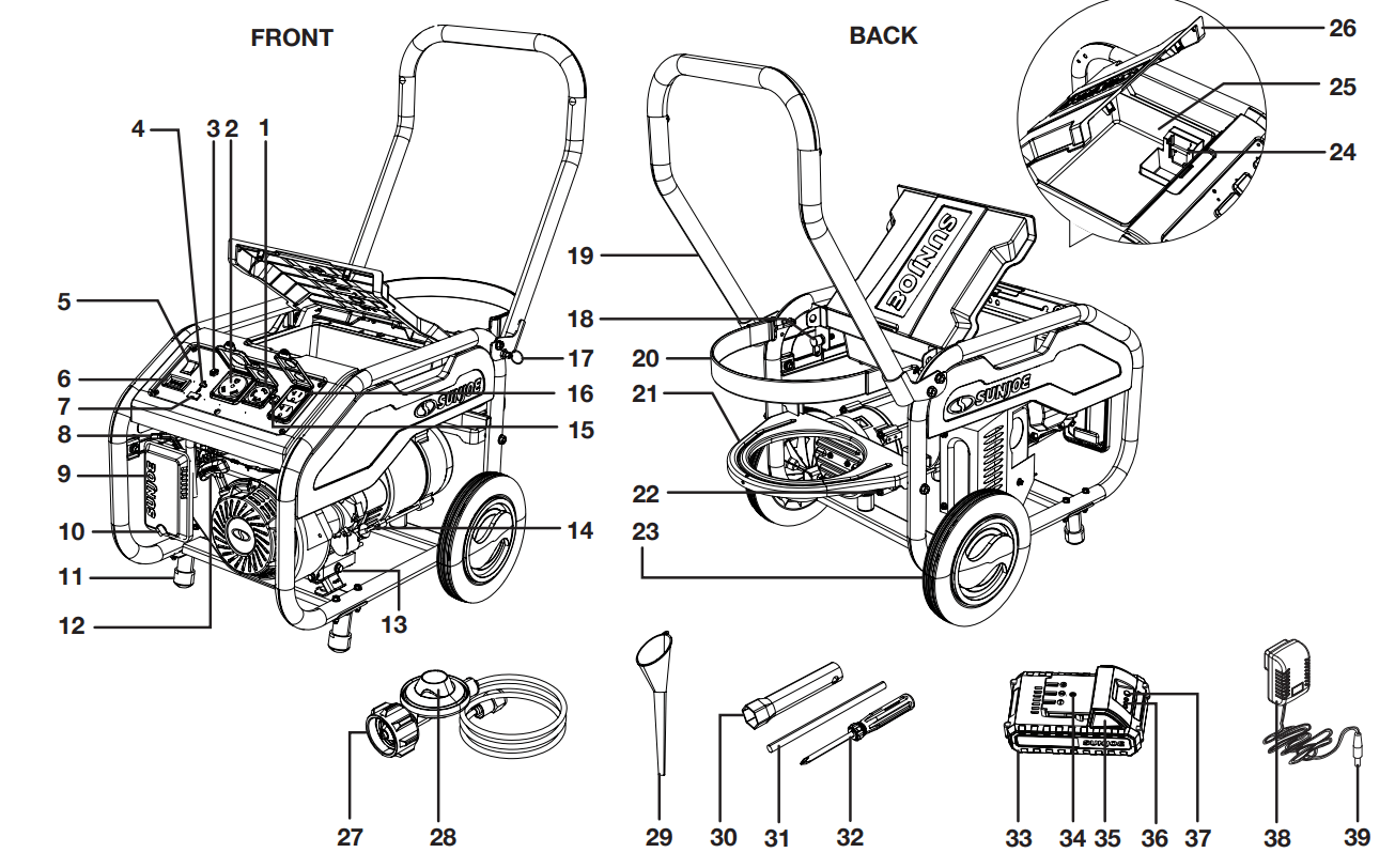
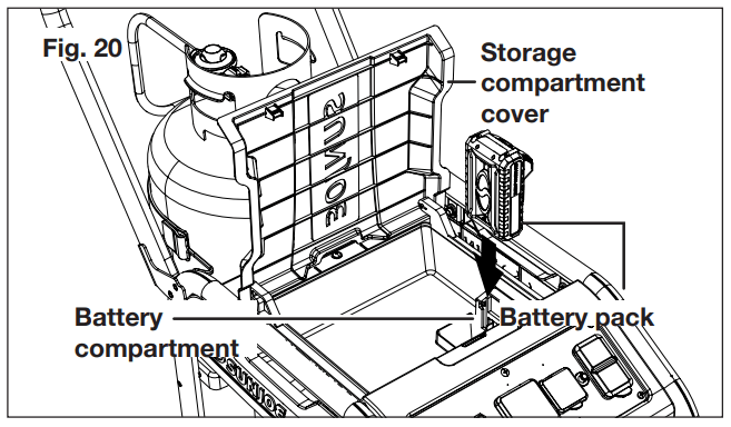
3. Open the storage compartment, and insert the battery into the battery compartment.
4. Make sure the propane cylinder is tested and installed as described, then open the cylinder valve completely.
5. Press the engine switch to ON position
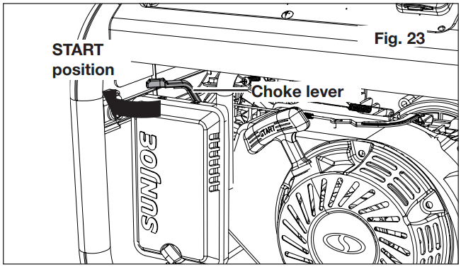
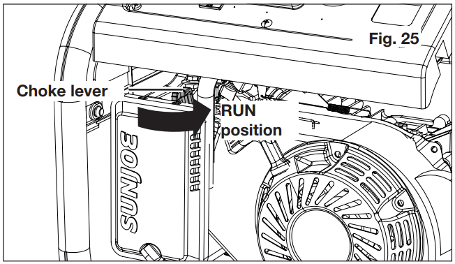
6. Move the choke lever all the way LEFT to the START position
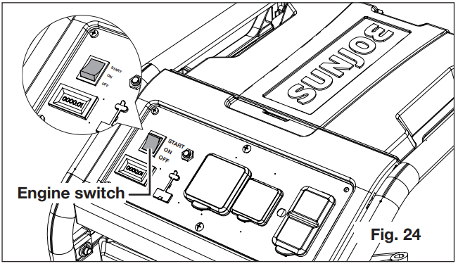
7. Press the engine switch to START position
NOTE: The battery may require charging before the generator can be electric started. In this case, start the engine by recoil start described below.
8. Allow the engine to run for 15 - 30 seconds, then move the choke lever all the way RIGHT to the RUN position
Recoil start
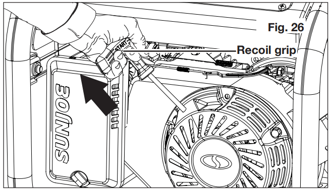
The generator can also be started by pulling the recoil grip, as described below.
1. Follow the step 1 to step 6 in Electric start section.
2. Grab the recoil grip and pull it out. Keep pulling until the engine runs
NOTE: Do not allow the grip to snap back after starting; return it gently to its original place.
3. Allow the engine to run for 15 - 30 seconds, then move the choke lever all the way RIGHT to the RUN position
Power Management
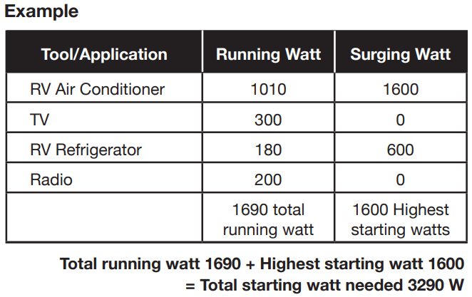
The generator can provide 4100 surge wattage and 3300 running wattage. Before plugging in any load, make sure the generator can supply enough continuous (running) and surge (starting) watts for the items you will power at the same time. Follow these steps.
1. Select the items you will power at the same time.
2. Total the continuous (running) watts of these items. This is the amount of power the generator must produce to keep the items running.
3. Estimate the surge (starting) watts you will need. Surge wattage is the short burst of power needed to start electric motor-driven tools or appliances such as a circular saw or refrigerator. Because not all motors start at the same time, total surge watts can be estimated by adding only the item(s) with the highest additional surge watts to the total rated watts from step 2.
To prolong the life of the generator and attached devices, it is important to take care when adding electrical loads to the generator. There should be nothing connected to the generator outlets before starting its engine. The correct and safe way to manage generator power is to sequentially add loads as follows:
With nothing connected to the generator, start the engine as described above. Let the engine warm up by running with no load for 2 - 3 minutes.
Plug in and turn on the first load, preferably the largest load you have.
Allow the generator output to stabilize (engine runs smoothly and attached device operates properly).
Plug in and turn on the next load.
Again, allow the generator to stabilize.
Repeat steps 4 and 5 for each additional load.
Never add more loads than the generator capacity. Take special care to consider surge loads in generator capacity as previously described.
WARNING! Do not overload the generator’s capacity. Exceeding the generator’s wattage/amperage capacity may damage the generator and/or electrical devices connected to it.
WARNING! While operating and storing, keep at least 3 feet of clearance on all sides of this product, including overhead.
Stop the Generator
Emergency stop
To stop the unit quickly in an emergency:
1. Turn the engine switch to the OFF position
2. Close the cylinder valve completely.
Normal stop
To stop the engine under normal operating conditions:
1. Remove any load from the generator.
2. Turn the engine switch to the OFF position.
3. Close the cylinder valve completely.
WARNING! Allow a minimum of 30 minutes of “cool down” time before storage. Heat created by muffler and exhaust gases could be hot enough to cause serious burns and/or ignite combustible objects.
Maintenance
Normal maintenance, replacement or repair of emission control devices and systems may be performed by any qualified repair establishment or individual with original or equivalent parts. Warranty and recall repairs must be performed by an authorized service center.
WARNING! Before inspecting, cleaning or servicing the machine, shut off engine, and remove the battery, wait for all moving parts to stop. Allow 30 minutes of cool down time before performing any maintenance. Failure to follow these instructions can result in serious personal injury or property damage.
WARNING! When servicing, use only recommended or equivalent replacement parts. Use of any other parts can create a hazard or cause product damage.
NOTE: Periodically inspect the entire product for damaged, missing, or loose parts such as screws, nuts, bolts, caps, etc. Tighten securely all fasteners and caps and do not operate this product until all missing or damaged parts are replaced.
General Maintenance
Keep the generator in a clean and dry environment where it is not exposed to dust, dirt, moisture, or corrosive vapors. Do not allow the cooling air slots in the generator to become clogged with foreign material such as leaves, etc.
Do not use a garden hose to clean the generator. Water entering the fuel system or other internal parts of the unit can cause problems that will decrease the life of the generator.
Close propane cylinder valve completely. Inspect all hoses before each use. Replace any damaged hoses before using the generator.
Cleaning the Generator
Use a soft bristle brush and/or vacuum cleaner to loosen and remove dirt and debris.
Clean air vents with low pressure air that does not exceed 25 psi.
Wipe the exterior surfaces of the generator with a damp cloth.
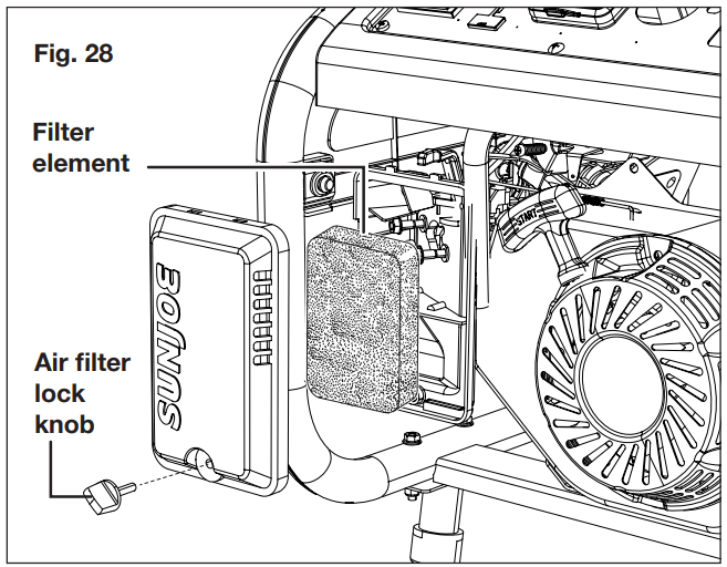
Cleaning the Air Filter
For proper performance and long life, keep air filter clean.
1. Rotate the air filter lock knob counterclockwise to release. Remove cover and the filter element inside.
2. Clean air vents with low pressure air that does not exceed 25 psi.
3. If the filter element is dirty, clean with warm, soapy water. Rinse and let dry.
4. Apply a light coat of engine lubricant to the filter element, then squeeze it out.
5. Replace the element in the air filter unit.
WARNING! Do not run the generator without the air filter. Rapid engine wear will result.
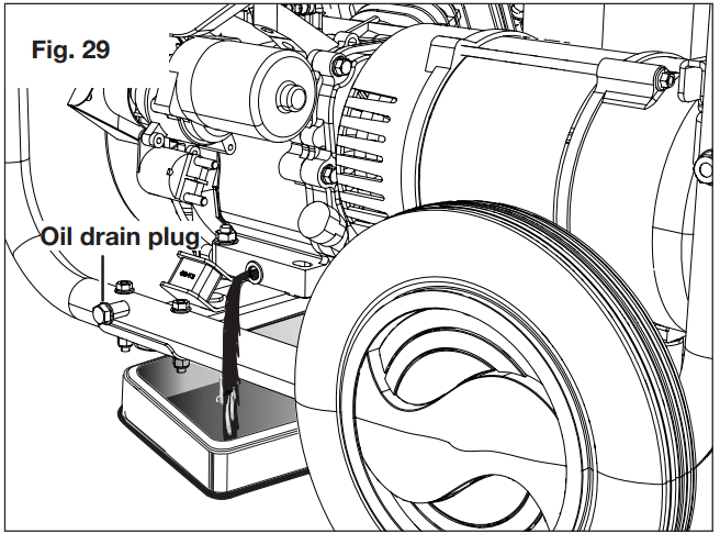
Change the Lubricant/Oil
1. Remove the oil cap/dipstick.
2. Place a container underneath the oil drain plug to collect used lubricant as it drains. Unscrew and remove the oil drain plug. Allow lubricant to drain completely.
WARNING! Drain the lubricant while the engine is still warm but not hot. Warm lubricant will drain quickly and more completely.
3. Reinstall the oil drain plug and tighten securely.
4. Refill with lubricant following the instructions in the Checking/Adding Lubricant section.
5. Reinstall the oil cap/dipstick.
NOTE: Used lubricant should be disposed of at an approved disposal site. See your local oil retailer for more information.
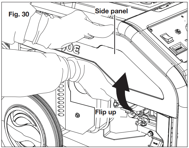
Spark Plug Maintenance
The spark plug must be properly gapped and free of deposits in order to ensure proper engine operation. To check:
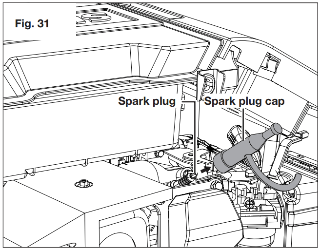
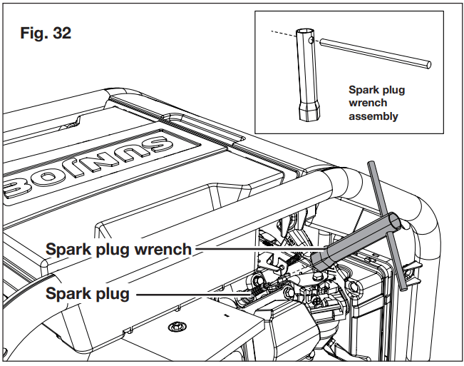
1. The spark plug is located behind the left side panel. To reach the spark plug, remove the left side panel by flipping the bottom of the side panel first, and pulling it out.
2. Remove the spark plug cap by pulling it out.
3. Clean any dirt from around base of spark plug.
4. Assemble the spark plug wrench by inserting the handle into the hole on the wrench. Using the assembled wrench, remove the spark plug.
5. Inspect spark plug for damage, and clean with a wire brush before reinstalling. If insulator is cracked or chipped, spark plug should be replaced.
6. Measure plug gap. The correct gap is 0.020 – 0.028 in. (0.5 - 0.7 mm). To widen gap, if necessary, carefully bend the ground (top) electrode. To lessen gap, gently tap ground electrode on a hard surface.
7. Seat spark plug in position; thread in by hand to prevent cross-threading.
8. Secure the spark plug with wrench. Do not over-tighten, replace the spark plug cap.
NOTE: An improperly tightened spark plug will become very hot and could damage the engine.
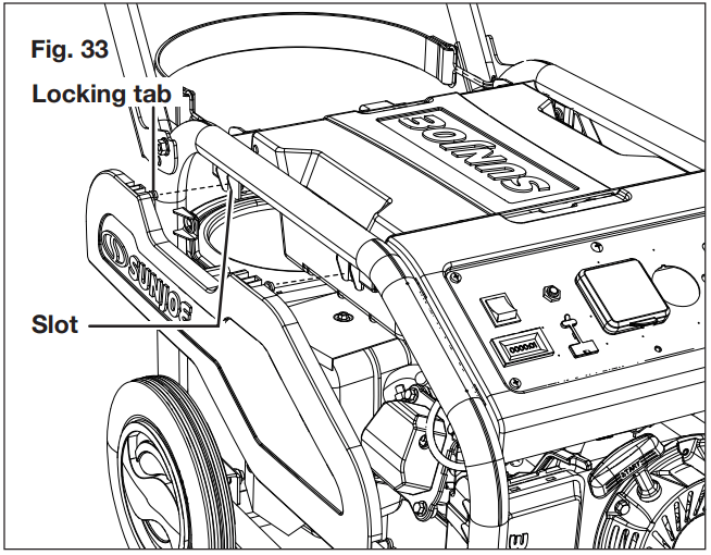
9. Replace the left side panel by inserting the locking tabs into the slots on the generator's frame, and push at the bottom of the side panel to lock it in place.
Cleaning the Exhaust Port and Muffler
Depending on the type and amount of lubricant used and/ or your operating conditions, the exhaust port and muffler may become blocked with carbon deposits. If you notice a power loss, you may need to remove these deposits to restore performance. We highly recommend that only qualified service technicians perform this service.
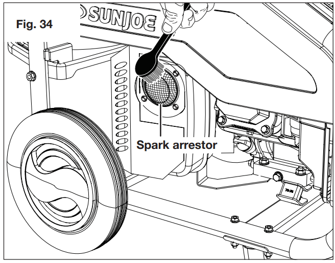
Cleaning the Spark Arrestor
1. Inspect the spark arrestor screen for breaks or holes. Replace if necessary.
2. Use a brush to remove carbon deposits from the spark arrestor screen as needed.
Troubleshooting
PROBLEM
POSSIBLE CAUSES
SOLUTIONS
Engine will not start.
Lubricant level is low.
Spark plug faulty, fouled, or improperly gapped.
Propane cylinder is empty.
Choke lever is in RUN position.
Engine is cold.
Engine is equipped with Low Oil Shutoff. If engine lubricant level is low, it must be filled before unit will start. Check engine lubricant level and fill, if necessary.
Replace spark plug.
Replace or refill propane cylinder.
Move choke lever to START position.
Move the generator to somewhere warm to start and then move to desired place.
Engine is hard to start
Weak spark at spark plug.
Replace spark plug or contact a qualified service center.
Engine lacks power.
Air filter element clogged.
Too much load.
Spark arrestor clogged.
Check air filter element. Clean or replace as needed.
Reduce load.
Clean the spark arrestor.
Electric start feature not working.
Engine switch is in OFF position.
Battery is not charged.
Turn engine switch ON.
Charge the battery.
AC receptacle does not work.
Circuit breaker is tripped.
Item plugged in is defective.
Reset the AC circuit breaker.
Try a different item.
Smell of propane gas.
Propane cylinder valve is open.
Hose or valve leaking.
Turn off cylinder valve immediately and tighten connections.
Turn off cylinder valve immediately and check for damaged hose or valve.
Gas leak detected from cylinder, regulator, or other connection.
Improper installation and loose connections.
Mechanical failure due to rusting or mishandling.
Tighten fittings.
Replace or refill propane cylinder.
Humming noise from regulator.
Cylinder valve turned on too quickly.
Turn off generator and close cylinder valve. Turn valve on slowly.
#1 How can i wire the generator to power my entire house?
Power Joe does not connect to your meter like a home standby generator. It is a portable generator that can be used to power multiple appliances (like lamps, TVs, electronics, sump pumps, kitchen appliances, microwaves, refrigerators, fans, heaters, small AC portable units) by using extension cords. Once Power Joe is running and positioned safely outside your home, you can connect the included 25 ft heavy-duty extension cord to Power Joe’s appropriate receptacle on its main dashboard. Then, run this extension cord inside your home through a back door or window and connect it to a suitable power strip/surge protector. This will then provide power to the power strip and allow you to plug in and power multiple appliances around your home.
#2 How do i use power joe to power multiple appilances inside my home?
To use Power Joe to power multiple appliances inside your home, start by situating Power Joe outside your home in a well-ventilated area away from doors and windows. (Power Joe must always remain outside your home since it contains a running engine.) Using the included 25-ft heavy duty extension cord, connect the cord to Power Joe’s appropriate receptacle on its main dashboard. Then, run the cord through a back door or window of your home, and connect the cord to a power strip/surge protector. This will then provide power to the power strip/surge protector, allowing you to plug in multiple appliances around your home like lamps, TVs, refrigerators, microwaves, portable A/C units, fans, heaters, medical equipment, and more.
Power Joe is not transfer switch ready. To connect the generator to your home, you will need to purchase an appropriately rated Generator Power Inlet Box and have this installed outside your home by an electrical professional. Please be sure to avoid overloading.