Loading ...
Loading ...
Loading ...
English 15
Step-by-step installation guide
Dim. Comparison
13
9
1
4
1
2
1
2
5
3
4
6
1
2
6
1
4
13
3
32
(332.4mm)
9
1
4
(235mm)
13
3
32
(332.4mm)
9
1
4
(235mm)
1
1
2
1
15
32
(37.3mm)
3
4
4
3
4
4
6
31
64
(164.5mm)
CUT OUT SLOT
FOR SMOOTH
FLAT BOTTOM
CABINETS ONLY
POWER
CORD
CUT OUT SLOT
FOR SMOOTH
FLAT BOTTOM
CABINETS ONLY
Screw exposure length
(Cabinet bottom to End of bolt)
without the Supporter.
28
32
1
26
32
~
(46mm) (22mm)
Screw exposure length
(Cabinet bottom to End of bolt)
when using the Supporter.
28
32
1
30
32
~
(49mm) (22mm)
NOTE
After assembling the screws in the D and E holes,
check the dimensions.
11
7
16
(290.75mm)
6
31
64
(164.5mm)
DE68-04708A-00
3
1
/2˝
(88.7mm)
1
27
/32˝
(47mm)
9
1
/4˝
(235mm)
1
15
/32˝
(37.3mm)
26
3
/16˝
(664.8mm)
1
27
/32˝
(47mm)
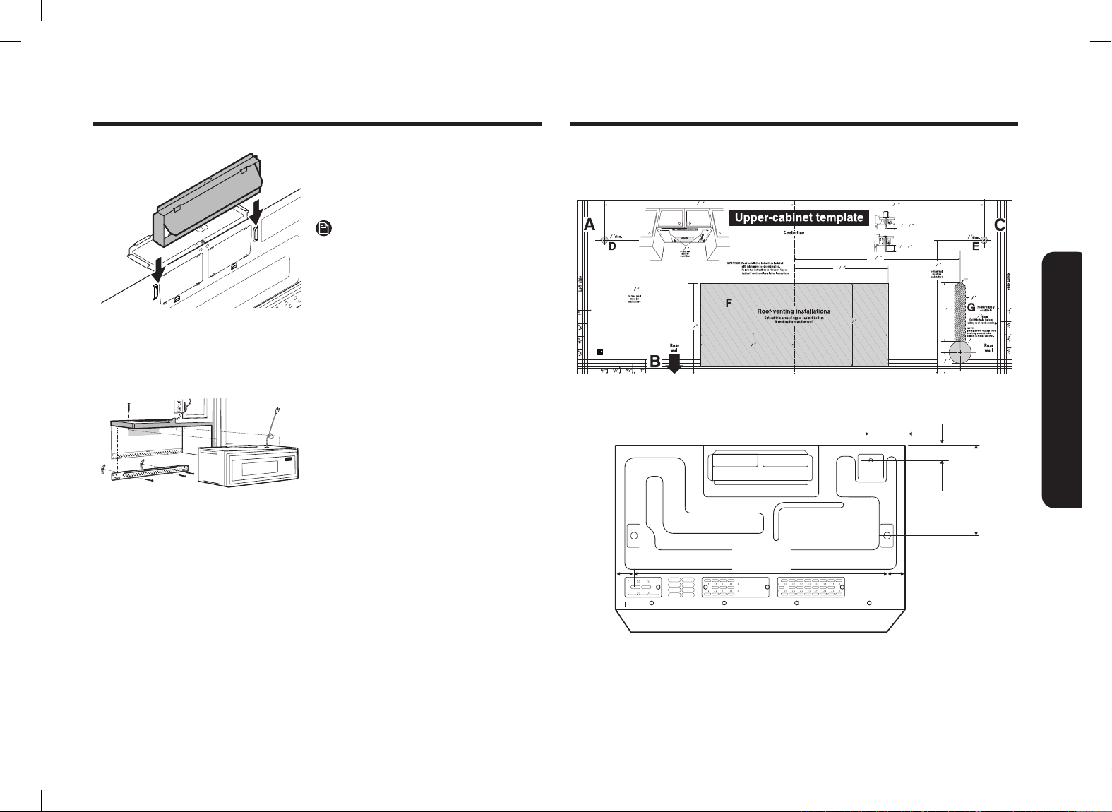
3. Remove the tape securing the
Damper.
4. Assemble the Damper as sliding from
top to bottom until stopped.
NOTE
Make sure Dampers swing freely.
Step 3. Installation
INSTALLATION OVERVIEW
F. CUT OUT FOR HORIZONTAL
OUTSIDE EXHAUSE
REAR WALL TEMPLATE
A. Prepare the Rear Wall (for outside
back exhaust/horizontal duct only)
B. Attach the Mounting Plate to the
Wall
C. Prepare the Cabinet above
D. Mount the Microwave Oven
E. Connect the Ductwork (for outside
top exhaust/vertical duct only)
Install_ME11A7510DG_AC_DE68-04709B-00_EN+CFR.indb 15Install_ME11A7510DG_AC_DE68-04709B-00_EN+CFR.indb 15 2021-06-16 �� 11:00:522021-06-16 �� 11:00:52
Loading ...
Loading ...
Loading ...