
Microwave Oven
Installation manual
ME11A7510** / ME11A7710**
Install_ME11A7510DG_AC_DE68-04709B-00_EN+CFR.indb 1Install_ME11A7510DG_AC_DE68-04709B-00_EN+CFR.indb 1 2021-06-16 �� 11:00:482021-06-16 �� 11:00:48
2 English
Before you begin
Before you beginContents
Before you begin 2
General information 3
Important safety instructions 3
Electrical requirements 3
Hood exhaust 4
Damage - Shipment/Installation 6
Parts included 6
Tools you will need 7
Mounting space 7
Step-by-step installation guide 9
Step 1. Placement of the mounting plate 9
Step 2. Ventilation types (choose a, b or c) 12
Step 3. Installation 15
Step 4. Before you use your microwave 19
Before you begin
ABOUT THIS MANUAL
READ THESE INSTRUCTIONS COMPLETELY AND CAREFULLY.
Important
• Save these instructions for local inspector’s use.
• Observe all governing codes and ordinances.
Important note to the installer
Be sure to leave these instructions with the Consumer.
Important note to the consumer
Keep these instructions with your user manual for future reference.
Skill level
Installation of this appliance requires basic mechanical and electrical skills.
Proper installation is the responsibility of the installer
Product failure due to improper installation is not covered under
the Warranty
Install_ME11A7510DG_AC_DE68-04709B-00_EN+CFR.indb 2Install_ME11A7510DG_AC_DE68-04709B-00_EN+CFR.indb 2 2021-06-16 �� 11:00:482021-06-16 �� 11:00:48
English 3
General information
General information
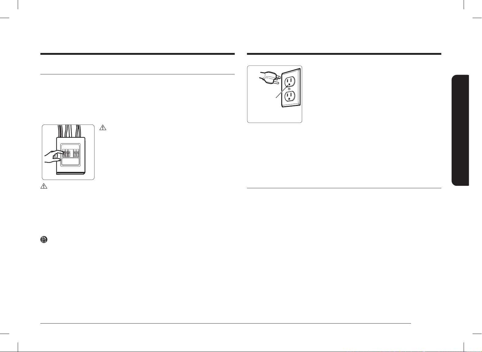
IMPORTANT SAFETY INSTRUCTIONS
This product requires a three-prong grounded outlet. The installer must perform a
ground continuity check on the power outlet box before beginning the installation
to ensure that the outlet box is properly grounded. If not properly grounded, or
if the outlet box does not meet electrical requirements noted (under ELECTRICAL
REQUIREMENTS), a qualied electrician should be employed to correct any
deciencies.
CAUTION
For personal safety, remove the house fuse or open the
circuit breaker before beginning the installation to avoid
severe or fatal shock injury.
CAUTION
• For personal safety, the mounting surface must be capable of supporting the
cabinet load in addition to the added weight of this 69 pound product, plus
additional oven loads of up to 50 pounds or a total weight of 119 pounds.
• For personal safety, do not install this product in cabinetry congured as an
island or a peninsula. The microwave oven must be mounted to BOTH a top
cabinet AND a wall.
NOTE
For easier installation and personal safety, we recommend that two people install
this product.
IMPORTANT – PLEASE READ CAREFULLY. FOR PERSONAL SAFETY,
THIS APPLIANCE MUST BE PROPERLY GROUNDED TO AVOID SEVERE
OR FATAL SHOCK.
Insure proper
ground exists
before use.
The power cord of this appliance is equipped with
a three-prong (grounding) plug which mates with a
standard three-prong (grounding) wall receptacle to
minimize the possibility of electric shock hazard from
this appliance.
You should have the wall receptacle and circuit checked by a qualied electrician
to make sure the receptacle is properly grounded.
If you have a standard two-prong wall receptacle, it is very important to have
it replaced with a properly grounded three-prong wall receptacle, installed by a
qualied electrician.
DO NOT, UNDER ANY CIRCUMSTANCES, CUT, DEFORM OR REMOVE ANY OF THE
PRONGS FROM THE POWER CORD. DO NOT USE WITH AN EXTENSION CORD.
ELECTRICAL REQUIREMENTS
Product rating is 120 volts AC, 60 Hertz, 14.5 amps and 1.7 kilowatts. This product
must be connected to a supply circuit of the proper voltage and frequency. Wire
size must conform to the requirements of the National Electrical Code or the
prevailing local code for this kilowatt rating. The power supply cord and plug
should be brought to a separate branch circuit single grounded outlet of at least
15 A and max of 20 A. The outlet box should be located in the cabinet above
the microwave oven. The outlet box and supply circuit should be installed by a
qualied electrician and conform to the National Electrical Code or the prevailing
local code.
Install_ME11A7510DG_AC_DE68-04709B-00_EN+CFR.indb 3Install_ME11A7510DG_AC_DE68-04709B-00_EN+CFR.indb 3 2021-06-16 �� 11:00:482021-06-16 �� 11:00:48
4 English
General information
General information
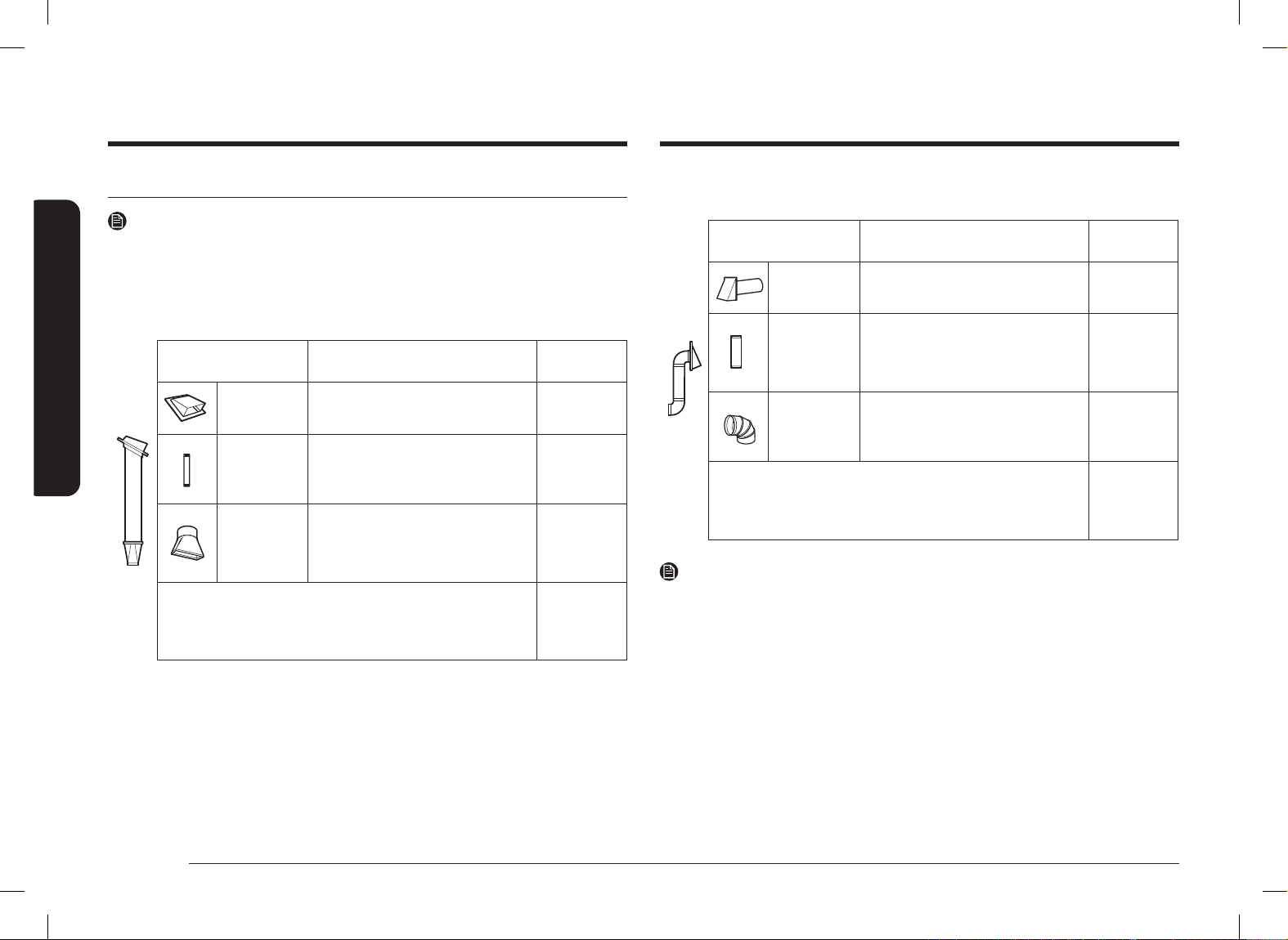
OUTSIDE BACK EXHAUST (EXAMPLE ONLY)
The following chart contains an example of one possible ductwork installation.
DUCT PIECES
EQUIVALENT
LENGTH
x
NUMBER
USED
=
EQUIVALENT
LENGTH
Wall Cap 40 ft. x (1) = 40 ft.
3 Ft. Straight
Duct
(3 ¼˝ x 10˝
Rectangular)
3 ft. x (1) = 3 ft.
90° Elbow 10 ft. x (2) = 20 ft.
Equivalent lengths of duct pieces
are based on actual tests and reect
requirements for good venting
performance with any vent hood.
Total
Length
= 63 ft.
NOTE
For back exhaust, care should be taken to align the exhaust with the space
between studs, or the wall should be prepared at the time it is constructed by
leaving enough space between the wall studs to accommodate exhaust.
HOOD EXHAUST
NOTE
Read these next two pages only if you plan to vent your exhaust to the outside. If
you plan to recirculate the air back into the room, proceed to page 12.
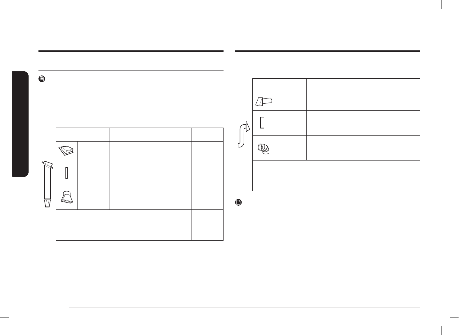
OUTSIDE TOP EXHAUST (EXAMPLE ONLY)
The following chart contains an example of one possible ductwork installation.
DUCT PIECES
EQUIVALENT
LENGTH
x
NUMBER
USED
=
EQUIVALENT
LENGTH
Roof Cap 24 ft. x (1) = 24 ft.
12 Ft.
Straight Duct
(6˝ Round)
12 ft. x (1) = 12 ft.
Rectangular-
to-Round
Transition
Adaptor*
5 ft. x (1) = 5 ft.
Equivalent lengths of duct pieces
are based on actual tests and reect
requirements for good venting
performance with any vent hood.
Total Length = 41 ft.
IMPORTANT:
If a rectangular-to-round transition adaptor is used, the bottom corners of the
damper will have to be cut to t, using the tin snips, in order to allow free
movement of the damper.
Install_ME11A7510DG_AC_DE68-04709B-00_EN+CFR.indb 4Install_ME11A7510DG_AC_DE68-04709B-00_EN+CFR.indb 4 2021-06-16 �� 11:00:482021-06-16 �� 11:00:48
English 5
General information
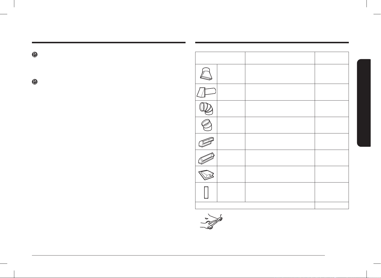
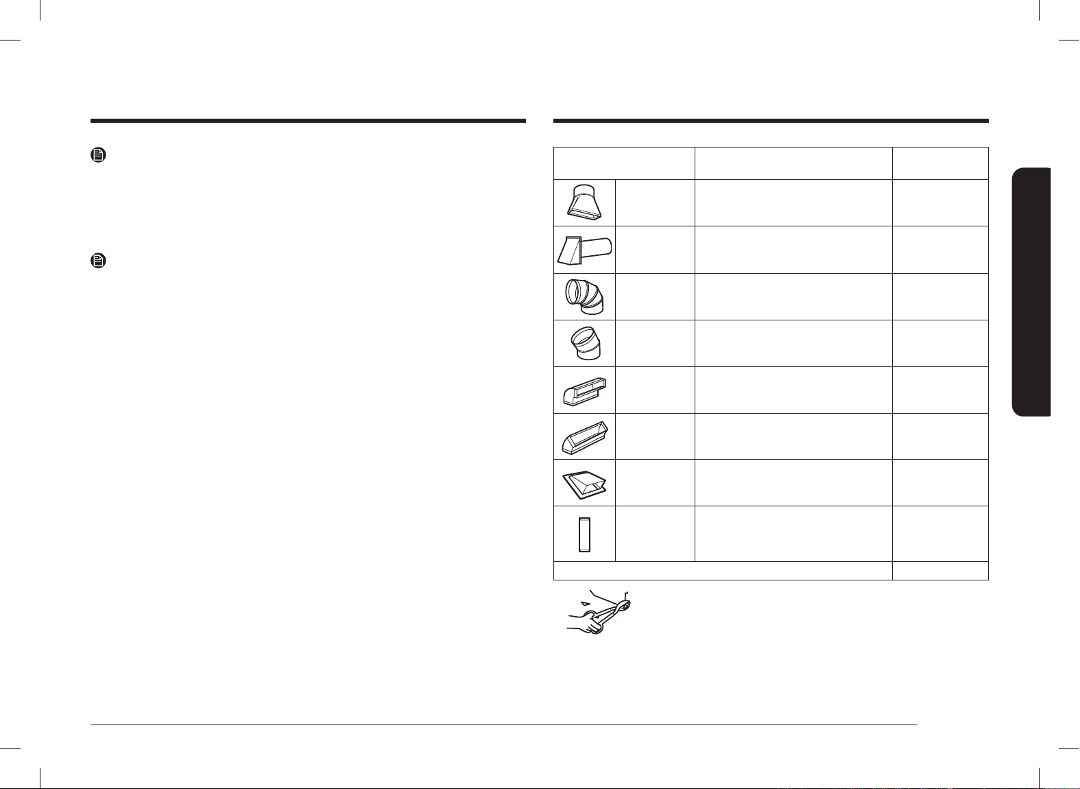
DUCT PIECES
EQUIVALENT
LENGTH
x
NUMBER
USED
=
EQUIVALENT
LENGTH
Rectangular-
to-Round
Transition
Adaptor*
5 ft. x ( ) = ft.
Wall Cap
40 ft. x ( ) = ft.
90 ° Elbow
10 ft. x ( ) = ft.
45 ° Elbow
5 ft. x ( ) = ft.
90 ° Elbow
25 ft. x ( ) = ft.
45 ° Elbow
5 ft. x ( ) = ft.
Roof Cap
24 ft. x ( ) = ft.
Straight Duct
6˝ Round or
3 ¼˝ x 10˝
Rectangular
1 ft. x ( ) = ft.
Total Ductwork = ft.
*IMPORTANT : If a rectangular-to-round transition adaptor is
used, the bottom corners of the damper will
have to be cut to t, using tin snips, to allow free
movement of the damper.
Equivalent lengths of duct pieces are based on
actual tests and reect the requirements for good
venting performance with any vent hood.
NOTE
If you need to install ducts, note that the total duct length of 3 ¼˝ x 10˝
rectangular or 6˝ diameter round duct should not exceed 140 equivalent feet.
Outside ventilation requires a HOOD EXHAUST DUCT. Read the following carefully.
NOTE
It is important that venting be installed using the most direct route and with as
few elbows as possible. This ensures clear venting of exhaust and helps prevent
blockages. Also, make sure dampers swing freely and nothing is blocking the
ducts.
Exhaust connection:
The hood exhaust has been designed to mate with a standard 3 ¼˝ x 10˝
rectangular duct.
If a round duct is required, a rectangular-to-round transition adaptor must be used.
Do not use less than a 6˝ diameter duct.
Maximum duct length:
For satisfactory air movement, the total duct length of 3 ¼˝ x 10˝ rectangular or 6˝
diameter round duct should not exceed 140 equivalent feet.
Elbows, transitions, wall and roof caps, etc. present additional resistance to airow
and are equivalent to a section of straight duct which is longer than their actual
physical size. When calculating the total duct length, add the equivalent lengths of
all transitions and adaptors plus the length of all straight duct sections. The chart
below shows you how to calculate total equivalent ductwork length using the
equivalent length in feet of some typical ducts.
Install_ME11A7510DG_AC_DE68-04709B-00_EN+CFR.indb 5Install_ME11A7510DG_AC_DE68-04709B-00_EN+CFR.indb 5 2021-06-16 �� 11:00:482021-06-16 �� 11:00:48

6 English
General information
General information
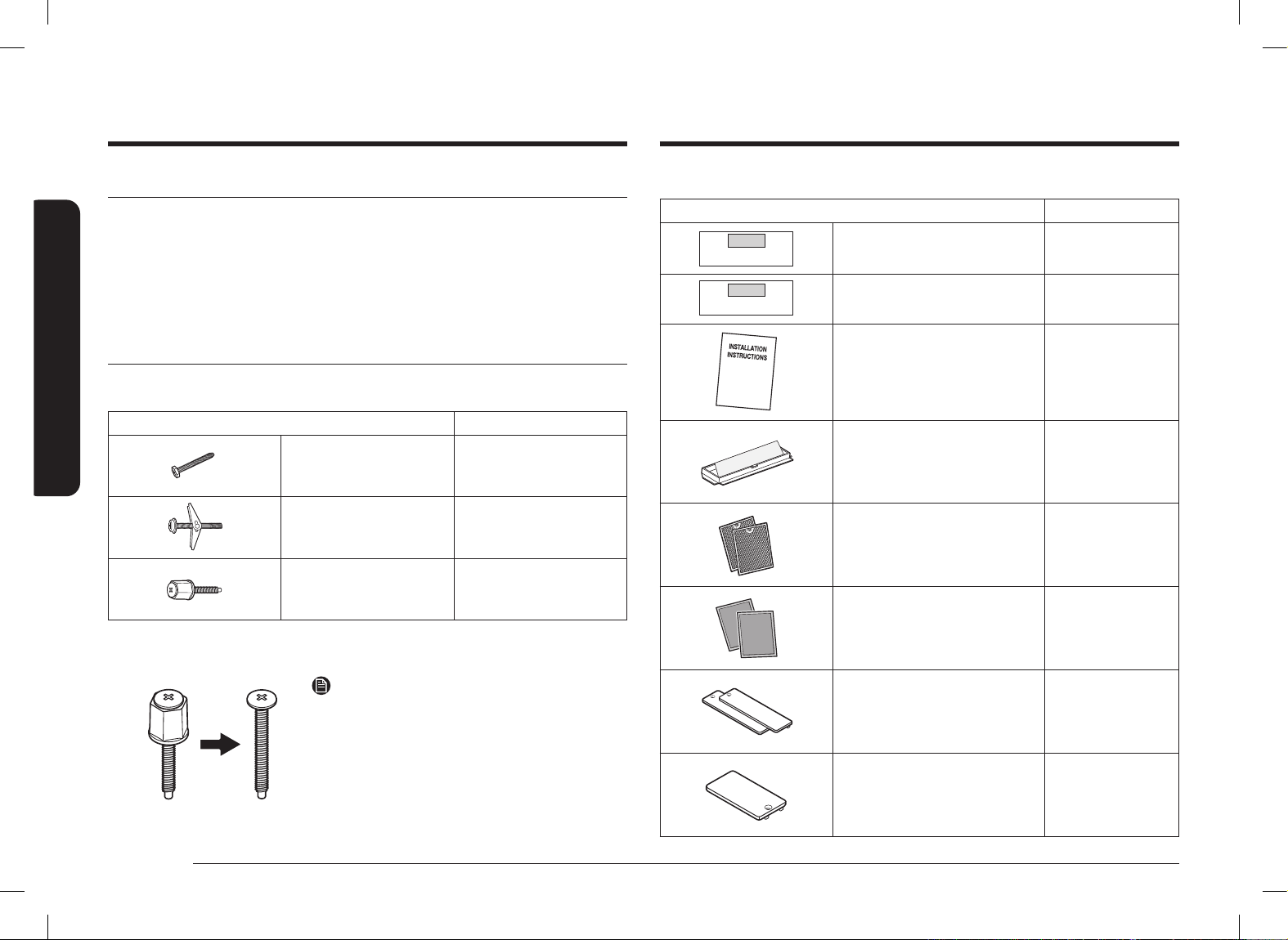
ADDITIONAL PARTS
PART QUANTITY
TOP CABINET TEMPLATE
REAR WALL TEMPLATE
Top Cabinet Template 1
TOP CABINET TEMPLATE
REAR WALL TEMPLATE
Rear Wall Template 1
Installation Instructions 1
Template
INSTALLATION
INSTRUCTIONS
Exhaust Adaptor 1
Separately Packed
Grease Filters
2
Separately Packed
Charcoal Filters
2
Cover Air-Right 2
Cover Air-Left 1
DAMAGE SHIPMENT/INSTALLATION
• If the unit is damaged in shipment, return the unit to the store in which it was
bought for repair or replacement.
• If the unit is damaged by the customer, repair or replacement is the
responsibility of the customer.
• If the unit is damaged by the installer (if other than the customer), repair
or replacement must be made by arrangement between the customer and
installer.
PARTS INCLUDED
HARDWARE PACKET
PART QUANTITY
Template
INSTALLATION
INSTRUCTIONS
Wood Screws 1
Template
INSTALLATION
INSTRUCTIONS
Toggle Bolts
(and wing nuts)
2
Self-aligning
Machine Screws
With Supporter
2
You will nd the installation hardware contained in a packet with the unit. Check to
make sure you have all these parts.
NOTE
If Cabinet Thickness is over 1 ˝, Remove
Supporter.
Install_ME11A7510DG_AC_DE68-04709B-00_EN+CFR.indb 6Install_ME11A7510DG_AC_DE68-04709B-00_EN+CFR.indb 6 2021-06-16 �� 11:00:492021-06-16 �� 11:00:49

English 7
General information
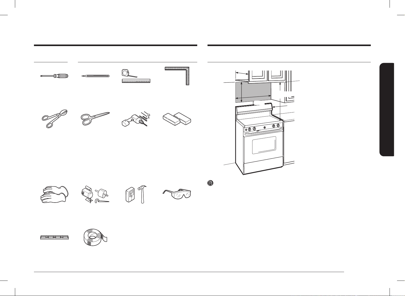
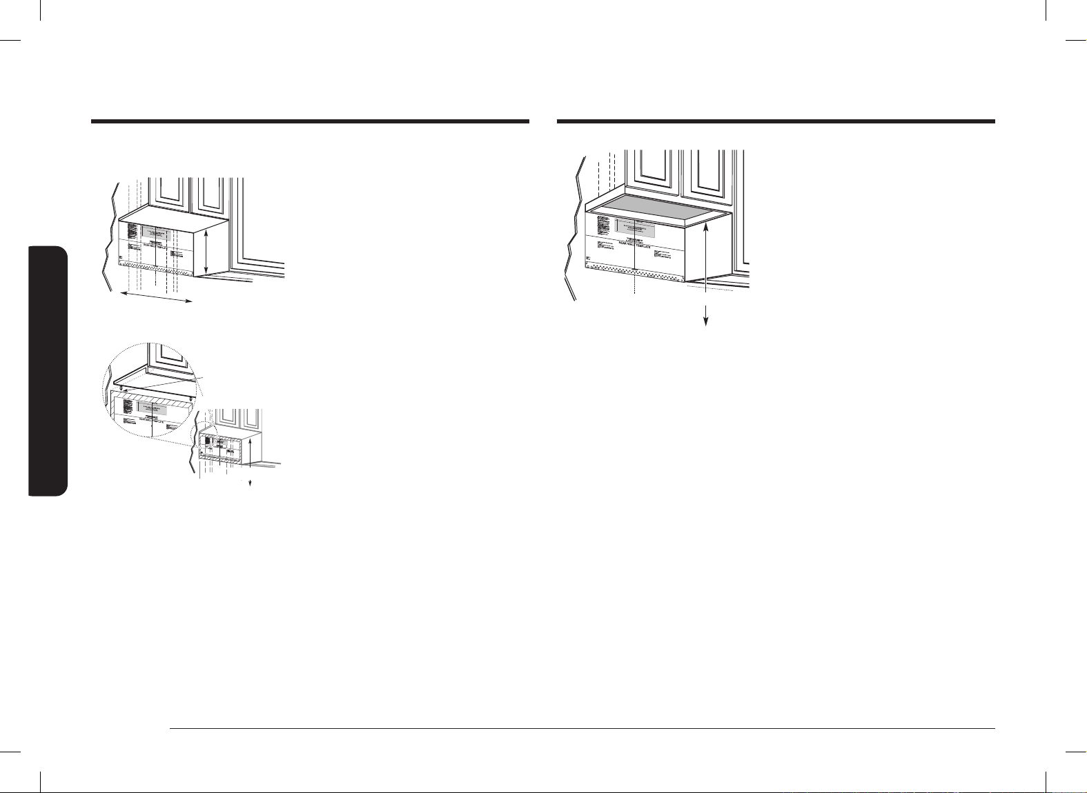
MOUNTING SPACE
24
1
/5˝
30˝
5˝
Bottom edge of the cabinet
needs to be 24
1
/5˝ or more
from the cooking surface.
Backsplash
12˝ max.
NOTE
• The space between the cabinets must be 30˝ wide and free of obstructions.
• This microwave oven is for installation over ranges up to 36˝ wide.
• If you are going to vent your microwave oven to the outside, see the Hood
Exhaust Section for exhaust duct preparation.
• If installing the microwave oven beneath smooth at cabinets, be careful to
follow the instructions on the top cabinet template for power cord clearance.
• Maximum cabinet depth above and beside the unit is 12˝.
• The dimensions provided are the minimum required for mounting the
microwave oven. Local codes and the practical use of the range will likely
require you to provide more than the 13.5˝ shown between the range and the
bottom of the microwave.
TOOLS YOU WILL NEED
#1 and #2 Phillips
screwdriver
Pencil Ruler or tape
measure and
straight edge
Carpenter square
(optional)
Tin snips (for cutting
damper, if required)
Scissors (to cut
template, if
necessary)
Electric drill with
3
/16˝,
1
/2˝ and
5
/8˝
drill bits
Filler blocks or
scrap wood pieces,
if needed for top
cabinet spacing
(used on recessed
bottom cabinet
installations only)
Gloves Saw (saber, hole or
keyhole)
Stud nder or
Hammer (optional)
Safety goggles
Level Duct and masking
tape
Install_ME11A7510DG_AC_DE68-04709B-00_EN+CFR.indb 7Install_ME11A7510DG_AC_DE68-04709B-00_EN+CFR.indb 7 2021-06-16 �� 11:00:492021-06-16 �� 11:00:49

8 English
General information
General information
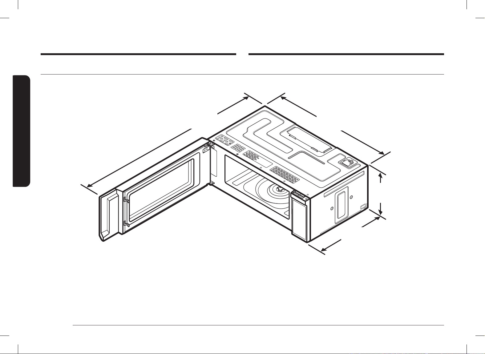
DIMENSION OF PRODUCT
46
11
/16˝
(1185.9mm)
With Plate mounting
29
7
/8˝
(758.8mm)
10
11
/16˝
(272.0mm)
19
3
/16˝
(486.7mm)
With Plate
mounting
Install_ME11A7510DG_AC_DE68-04709B-00_EN+CFR.indb 8Install_ME11A7510DG_AC_DE68-04709B-00_EN+CFR.indb 8 2021-06-16 �� 11:00:502021-06-16 �� 11:00:50

English 9
Step-by-step installation guide
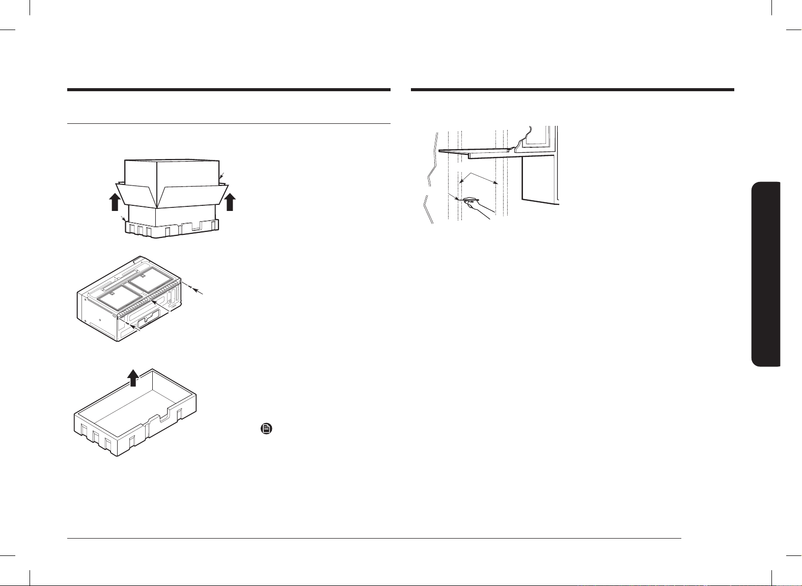
B. Finding the wall studs
Center
Wall Studs
1. Find the studs using one of the
following methods:
A. With a stud nder – a magnetic
device which locates nails.
OR
B. Use a hammer to tap lightly
across the mounting surface until
you hear a solid sound. This will
indicate a stud location.
2. After locating the stud(s), locate the
stud’s center by probing the wall
with a small nail to nd the edges of
the stud. Then, place a mark halfway
between the edges. The center of
any adjacent studs should be 16˝ or
24˝ from this mark.
3. Draw a line down the center of the
studs.
THE MICROWAVE MUST BE CONNECTED TO AT LEAST ONE WALL STUD.
Step-by-step installation guide
Step 1. Placement of the mounting plate
A. Removing the microwave oven from the carton/Removing the mounting plate
Carton
Styrofoam
Mounting Plate
Screws
Screws
1. Remove the installation
instructions, Exhaust
Adaptor, lters, glass tray,
and the small hardware
bag. Do not remove the
Styrofoam protecting the
front of the oven.
2. Fold back all 4 carton aps
fully against carton sides.
Then carefully roll the oven
and carton over onto the
top side. The oven should be
resting in the Styrofoam.
3. Pull the carton up and off
the oven.
4. Remove and properly
discard plastic bags.
5. Remove the 2 screws from
the mounting plate. This
plate will be used as the
rear wall template and for
mounting.
NOTE
Retain the two screws. You will
need to re-insert the screws in
their original locations after you
have removed the mounting
plate.
Install_ME11A7510DG_AC_DE68-04709B-00_EN+CFR.indb 9Install_ME11A7510DG_AC_DE68-04709B-00_EN+CFR.indb 9 2021-06-16 �� 11:00:502021-06-16 �� 11:00:50

10 English
Step-by-step installation guide
Step-by-step installation guide
C. Determining wall plate location under your cabinet
C
L
At least 30˝
Plate position – beneath a at bottom
cabinet.
Draw a vertical line on the wall at the
center of the 30˝ wide space. Tape the Rear
Wall Template onto the wall so that the top
of the template touches the bottom of the
cabinet and the centerline on the template
lines up with the line you drew on the wall.
`
i
Plate position – beneath recessed bottom
cabinet with front overhang
Draw a horizontal
line to mark how
far the inside of
the front overhang
descends below
the cabinet.
24
1
/5˝
Plate position – beneath a recessed bottom
cabinet with a front overhang.
Draw a vertical line on the wall at the
center of the 30˝ wide space. Draw a
second, horizontal line on the wall below
the cabinet to mark how far the inside of
the front overhang descends below the
cabinet. Tape the Rear Wall Template onto
the wall so that the top of the template
touches the bottom of the horizontal line
and the centerline on the template lines up
with the vertical line.
C
L
24
1
/5˝
Plate position – beneath a framed recessed
cabinet bottom.
Draw a vertical line on the wall at the
center of the 30˝ wide space. Tape the Rear
Wall Template onto the wall so that the top
of the template touches the bottom of the
cabinet frame and the centerline on the
template lines up with the line you drew
on the wall.
Your cabinets may have decorative trim that interferes with the microwave
installation. Remove the decorative trim to install the microwave properly and to
make it level.
THE MICROWAVE MUST BE LEVEL.
Use a level to make sure the cabinet bottom is level.
Install_ME11A7510DG_AC_DE68-04709B-00_EN+CFR.indb 10Install_ME11A7510DG_AC_DE68-04709B-00_EN+CFR.indb 10 2021-06-16 �� 11:00:502021-06-16 �� 11:00:50
English 11
Step-by-step installation guide
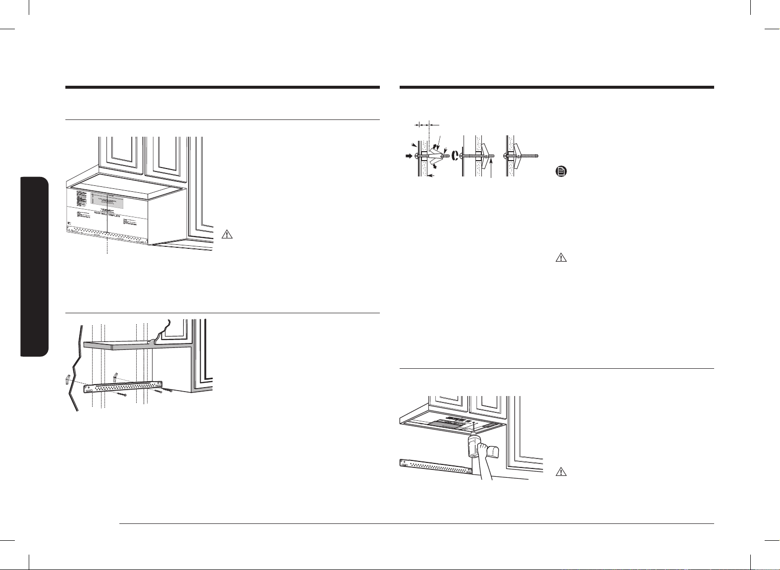
1. Draw a horizontal line on the wall at the bottom of the “Rear Wall Template”.
2. Drill
5
/8˝ holes for toggle bolts in 2 locations (Hole A, Hole B) as shown in the
illustration above. If the location of a hole lines up with a stud, drill a
3
/16˝ hole
for a wood screw. You cannot use a toggle bolt to attach the wall plate to a
stud.
NOTE
DO NOT MOUNT THE PLATE AT THIS TIME.
D. Aligning the wall plate
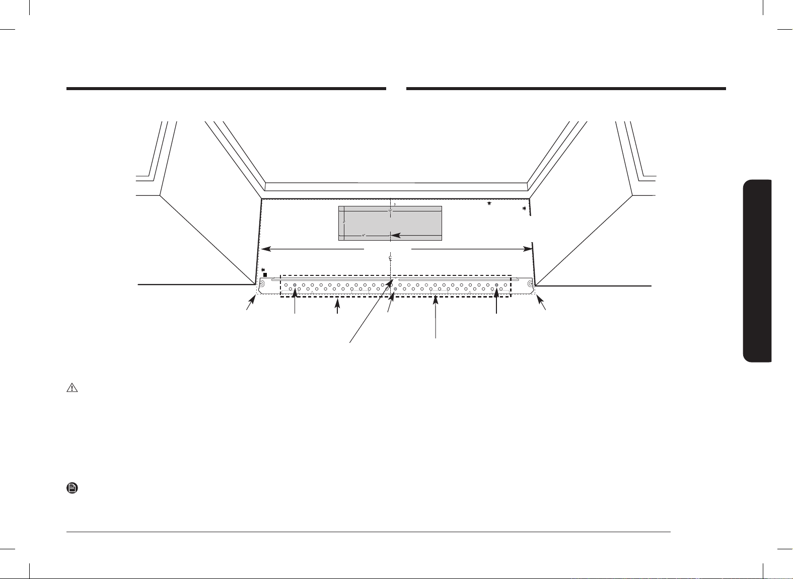
NOTE: IT IS VERY IMPORTANT TO
READ AND FOLLOW THE DIRECTIONS
IN THE INSTALLATION INSTRUCTIONS
BEFORE PROCEEDING WITH THIS
REAR WALL TEMPLATE.
This Rear Wall Template serves to position the bottom
mounting plate and to locate the horizontal exhaust outlet
1. Use a level to check that the template is positioned accurately.
2. Locate and mark at least one stud on the left or right side of the centerline.
NOTE:
It is important to use at least one wood screw mounted rmly in a stud to support
the weight of the microwave. Mark two additional, evenly spaced locations for
the supplied toggle bolts.
3. Drill holes in the marked locations. Where there is a stud, drill a 3/16” hole for wood screws,
for holes that do not line up with a stud, drill 5/8” holes for toggle bolts
NOTE:
DO NOT INSTALL THE MOUNTING PLATE AT THIS TIME.
4. Remove the template from the rear wall.
5. Review the Installation Instruction book for your installation situation.
Français au verso.
3/8
"
TO EDGE
F. CUT OUT FOR HORIZONTAL
OUTSIDE EXHAUSE
CUT HOLE THROUGH REAR WALL FOR EXHAUST ADAPTOR
REAR WALL TEMPLATE
CAUTION - IF EXHAUST ADAPTOR IS POSITIONED OUTSIDE
RECOMMENDED DIMENSION, GREASE-LADEN AIR WILL
DISCHARGE INTO HOUSE STRUCTURE.
Locate and mark holes to align with holes in the mounting plate.
IMPORTANT:
LOCATE AT LEAST ONE STUD ON EITHER SIDE OF THE CENTERLINE.
MARK THE LOCATION FOR 2 ADDITIONAL, EVENLY SPACED TOGGLE
BOLTS IN THE MOUNTING PLATE AREA.
IT IS RECOMMENDED TO INSTALL BOLTS IN A, B, AND C HOLES. THE LOCATION
MAY BE SUBJECT TO CHANGE ACCORDING TO CIRCUMSTANCES BUT IT IS
RECOMMENDABLE TO INSTALL THEM NEAR THE THREE HOLES MENTIONED.
Trim the rear wall template along the dotted line.
Trim the rear wall template along the dotted line.
Locate and mark holes to align with holes in the mounting plate.
IMPORTANT:
LOCATE AT LEAST ONE STUD ON EITHER SIDE OF THE CENTERLINE.
MARK THE LOCATION FOR 2 ADDITIONAL, EVENLY SPACED TOGGLE
BOLTS IN THE MOUNTING PLATE AREA.
IT IS RECOMMENDED TO INSTALL BOLTS IN A, B, AND C HOLES. THE LOCATION
MAY BE SUBJECT TO CHANGE ACCORDING TO CIRCUMSTANCES BUT IT IS
RECOMMENDABLE TO INSTALL THEM NEAR THE THREE HOLES MENTIONED.
Printed in Malaysia
DE68-04707B-00
30
"
MINIMUM WIDTH REQUIRED
Draw a horizontal line on the wall along the
bottom of the “Rear Wall Template”.
Draw a vertical line on the
wall to mark the center of
the cabinet above.
Horizontal Line
Area E
Centerline
notches
Hole A
Hole B
Hole C
Horizontal Line
CAUTION
Wear gloves to avoid cutting ngers on sharp edges.
3. Holes A and B are inside area E. If none of these holes line up with a stud,
nd a stud in area E that lines up with a hole circle in Area E, and then drill
a
3
/16˝ hole into it for a wood screw. You must have at least one wood screw
mounted rmly into a stud to support the weight of the microwave. Set the
mounting plate aside.
Install_ME11A7510DG_AC_DE68-04709B-00_EN+CFR.indb 11Install_ME11A7510DG_AC_DE68-04709B-00_EN+CFR.indb 11 2021-06-16 �� 11:00:512021-06-16 �� 11:00:51
12 English
Step-by-step installation guide
Step-by-step installation guide
Step 2. Ventilation types (choose A, B or C)
This microwave oven is compatible with the following three types of ventilation:
A. Outside top exhaust
(vertical duct)
B. Recirculating
(non-vented ductless)
Bracket
C. Outside back exhaust
(horizontal duct)
NOTE
This microwave is shipped assembled for Recirculating. An Exhaust Adaptor is
shipped assembled and attached to the ller-upper. Select the type of ventilation
required for your installation and proceed to that section.
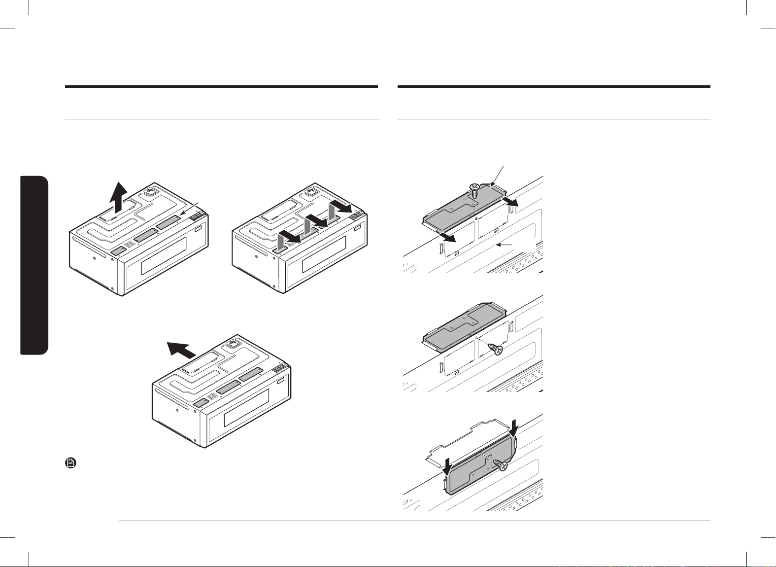
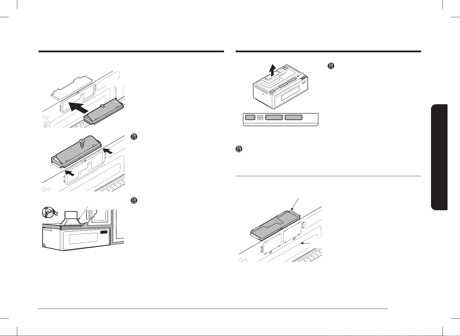
A. Outside top exhaust (vertical duct)
A1. ADAPTING THE COVER PANEL FOR THE EXHAUST ADAPTOR
Cover
Panel
Back
Panel
1. Remove 1 screw from Cover Panel
and take off Cover Panel.
2. Remove 1 screw from Back Panel.
3. Assemble the Cover Panel as sliding
from top to bottom and the screw
that was removed from Back Panel.
Install_ME11A7510DG_AC_DE68-04709B-00_EN+CFR.indb 12Install_ME11A7510DG_AC_DE68-04709B-00_EN+CFR.indb 12 2021-06-16 �� 11:00:512021-06-16 �� 11:00:51
English 13
Step-by-step installation guide
Bracket
The marked Brackets should not
have Vent holes.
NOTE
You must check bracket picture according
to ventilation type at page 12.
NOTE
Apply A1 and A2 equally.
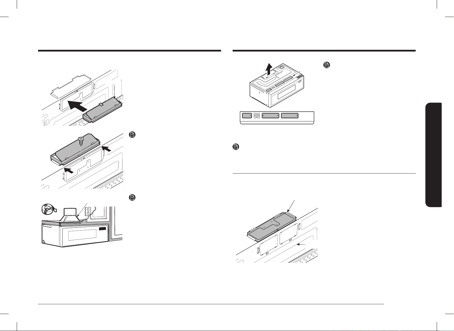
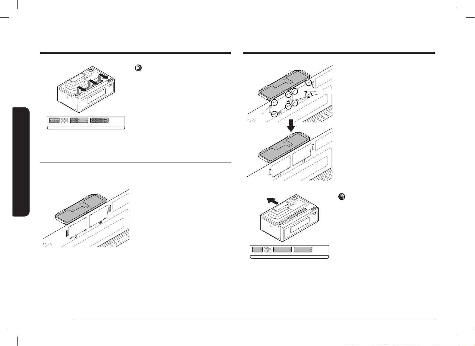
B. Recirculating (non-vented ductless)
B1. Adapting the COVER PANEL for recirculation
Cover
Panel
Back
Panel
1. Make sure the Cover Panel is
assembled properly. (Top assembly)
A2. INSTALLATION DAMPER
Damper
1. Remove the tape securing the
Damper.
2. Assemble the Damper as sliding from
back to front until stopped.
NOTE
Make sure Dampers swing freely.
House Duct
House Duct
NOTE
• You must attach the House Duct to
the Exhaust Adaptor after installation
is complete.
• You must seal Exhaust Duct joints
using Duct Tape.
Install_ME11A7510DG_AC_DE68-04709B-00_EN+CFR.indb 13Install_ME11A7510DG_AC_DE68-04709B-00_EN+CFR.indb 13 2021-06-16 �� 11:00:512021-06-16 �� 11:00:51

14 English
Step-by-step installation guide
Step-by-step installation guide
Plate
8EA
After removing Plates
2. Cut 8 area to remove plates using
nipper.
The marked Brackets should not
have Vent holes.
NOTE
You must check bracket picture according
to ventilation type at page 12.
The marked Brackets should have
Vent holes.
NOTE
• The Exhaust Adaptor with
the Damper is not needed for
recirculating type. You may want to
save them for possible future use.
• You must check bracket picture
according to ventilation type at page
12.
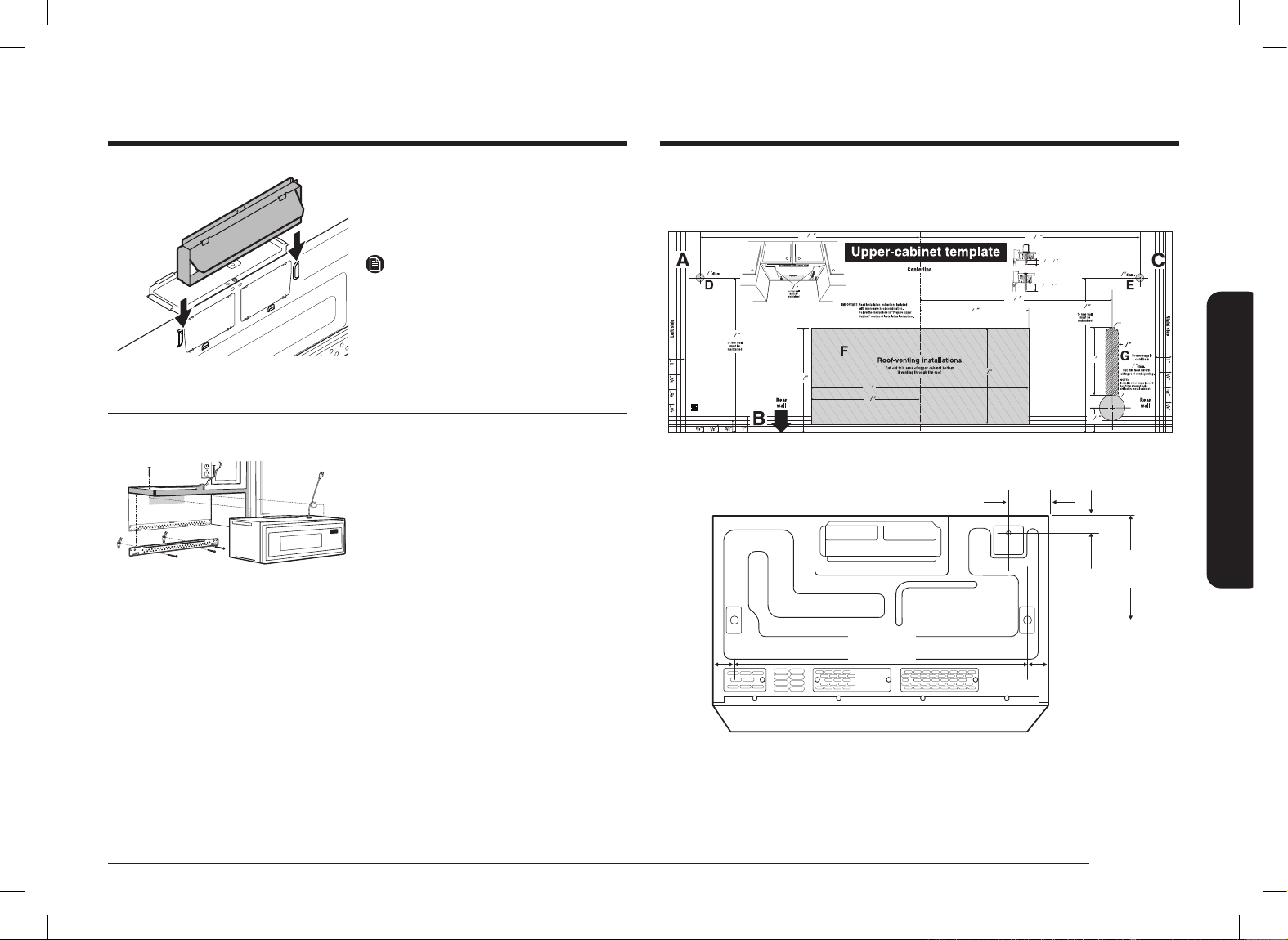
C. Outside back exhaust (horizontal duct)
C1. Adapting the COVER PANEL for outside back exhaust
1. Make sure the Cover Panel is
assembled properly. (Top assembly)
Install_ME11A7510DG_AC_DE68-04709B-00_EN+CFR.indb 14Install_ME11A7510DG_AC_DE68-04709B-00_EN+CFR.indb 14 2021-06-16 �� 11:00:512021-06-16 �� 11:00:51
English 15
Step-by-step installation guide
Dim. Comparison
13
9
1
4
1
2
1
2
5
3
4
6
1
2
6
1
4
13
3
32
(332.4mm)
9
1
4
(235mm)
13
3
32
(332.4mm)
9
1
4
(235mm)
1
1
2
1
15
32
(37.3mm)
3
4
4
3
4
4
6
31
64
(164.5mm)
CUT OUT SLOT
FOR SMOOTH
FLAT BOTTOM
CABINETS ONLY
POWER
CORD
CUT OUT SLOT
FOR SMOOTH
FLAT BOTTOM
CABINETS ONLY
Screw exposure length
(Cabinet bottom to End of bolt)
without the Supporter.
28
32
1
26
32
~
(46mm) (22mm)
Screw exposure length
(Cabinet bottom to End of bolt)
when using the Supporter.
28
32
1
30
32
~
(49mm) (22mm)
NOTE
After assembling the screws in the D and E holes,
check the dimensions.
11
7
16
(290.75mm)
6
31
64
(164.5mm)
DE68-04708A-00
3
1
/2˝
(88.7mm)
1
27
/32˝
(47mm)
9
1
/4˝
(235mm)
1
15
/32˝
(37.3mm)
26
3
/16˝
(664.8mm)
1
27
/32˝
(47mm)
3. Remove the tape securing the
Damper.
4. Assemble the Damper as sliding from
top to bottom until stopped.
NOTE
Make sure Dampers swing freely.
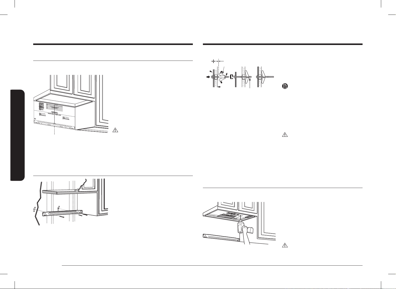
Step 3. Installation
INSTALLATION OVERVIEW
F. CUT OUT FOR HORIZONTAL
OUTSIDE EXHAUSE
REAR WALL TEMPLATE
A. Prepare the Rear Wall (for outside
back exhaust/horizontal duct only)
B. Attach the Mounting Plate to the
Wall
C. Prepare the Cabinet above
D. Mount the Microwave Oven
E. Connect the Ductwork (for outside
top exhaust/vertical duct only)
Install_ME11A7510DG_AC_DE68-04709B-00_EN+CFR.indb 15Install_ME11A7510DG_AC_DE68-04709B-00_EN+CFR.indb 15 2021-06-16 �� 11:00:522021-06-16 �� 11:00:52
16 English
Step-by-step installation guide
Step-by-step installation guide
Bolt End
Mounting
Plate
Toggle
Bolt
Wall
Toggle Wings
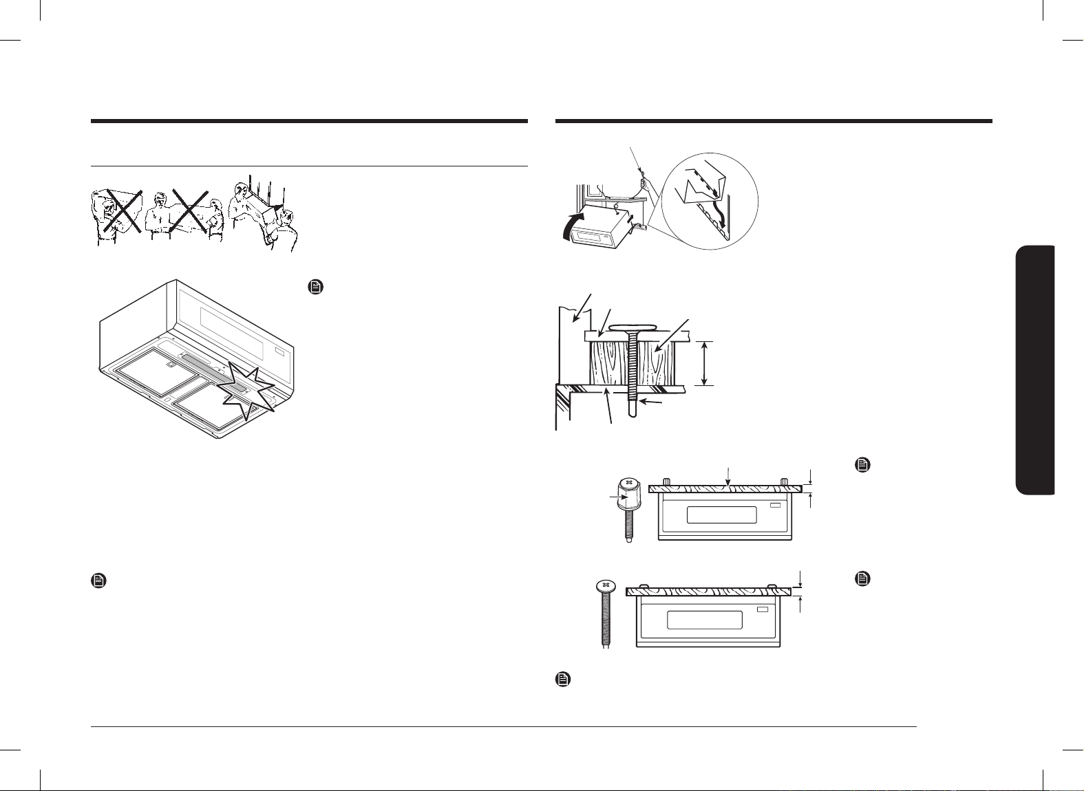
3. Place the mounting plate against
the wall, pinch the wings of each
toggle together, and then insert the
toggle wings of each toggle into and
through the holes in the wall.
NOTE
Before tightening the toggle bolts and
wood screw, make sure the bottom
of the Mounting plate runs along the
bottom Horizontal line of the “Rear wall
Template” and the Mounting plate is
properly centered under the cabinet.
CAUTION
Be careful to avoid pinching your ngers
between the back of the mounting plate
and the wall.
4. Tighten all bolts. Pull the plate away
from the wall to help tighten the
bolts. Tighten the screw.
C. Use the top cabinet template to prepare the cabinet above
You need to drill holes for the top support screws and a hole large enough for the
power cord to t through.
• Read the instructions on the TOP
CABINET TEMPLATE.
• Tape it underneath the top cabinet.
• Drill the holes, following the
instructions on the TOP CABINET
TEMPLATE.
CAUTION
Wear safety goggles when drilling holes
in the cabinet bottom.
A. Prepare the rear wall for outside back exhaust
You need to cut an opening in the rear wall for outside exhaust.
C
L
• Read the instructions for outside
back exhaust on the REAR WALL
TEMPLATE.
• Tape the REAR WALL TEMPLATE to
the rear wall.
• Cut the opening, following the
instructions on the REAR WALL
TEMPLATE.
CAUTION
Do not cut an opening in the rear wall
if you are installing the microwave with
vertical duct or non-vented ductless
ventilation.
B. Attach the mounting plate to the wall
Attach the plate to the wall using toggle
bolts. At least one wood screw must be
used to attach the plate to a wall stud.
1. Remove the toggle wings from the
bolts.
2. Insert the bolts into the mounting
plate through the holes designated
to go into drywall, and then reattach
the toggle wings so that ¾˝ of the
bolt protrudes beyond the wing.
Install_ME11A7510DG_AC_DE68-04709B-00_EN+CFR.indb 16Install_ME11A7510DG_AC_DE68-04709B-00_EN+CFR.indb 16 2021-06-16 �� 11:00:522021-06-16 �� 11:00:52
English 17
Step-by-step installation guide
Equivalent
to Depth
of Cabinet
Recess
Cabinet Bottom Shelf
Microwave Oven Top
Cabinet Front
Filler Block
Self-Aligning
Screw
1. Lift the microwave, tilt it forward,
and hook the slots at the back
bottom edge onto the four lower
tabs of the mounting plate.
2. Rotate the front of the oven up
against the cabinet bottom.
3. Insert a self-aligning screw
through the top center cabinet
hole. Temporarily secure the oven
by turning the screw at least two
full turns after the threads have
engaged. (It will be completely
tightened later.) Be sure to keep
the power cord tight. Be careful not
to pinch the cord, especially when
mounting ush to the bottom of
cabinet.
Thickness of cabinet
1
/16
~
15
/16 ˝
Supporter
NOTE
If Cabinet Thickness is
Under 1 ˝, Use Supporter.
1
~
2˝
NOTE
If Cabinet Thickness
is over 1 ˝, Remove
Supporter from the Self-
Aligning Screw.
NOTE
The self-aligning screw can be installed up to 1
15
/16 ˝ (49mm).
D. Mount the microwave oven
FOR EASIER INSTALLATION AND
PERSONAL SAFETY, WE RECOMMEND
THAT TWO PEOPLE INSTALL THIS
MICROWAVE OVEN.
IMPORTANT: Do not grip or use the
handle during installation.
NOTE
• If your cabinet is metal, use the
nylon grommet in the power cord
hole to prevent the cord from being
cut.
• Filler blocks are required when
mounting this unit under any cabinet
with a recessed bottom or front
overhang. (See page 10.)
IMPORTANT: The case damage that will
occur from over tightening
screws if you do not use
ller blocks is not covered
under warranty.
IMPORTANT: Be careful not to damage
the lower Lamp Glass during
handling.
NOTE
When mounting the microwave oven, thread the power cord through hole in the
bottom of the top cabinet. Keep it tight throughout Steps 1–3. Do not pinch the
cord or lift the oven by pulling cord.
Install_ME11A7510DG_AC_DE68-04709B-00_EN+CFR.indb 17Install_ME11A7510DG_AC_DE68-04709B-00_EN+CFR.indb 17 2021-06-16 �� 11:00:532021-06-16 �� 11:00:53
18 English
Step-by-step installation guide
Step-by-step installation guide
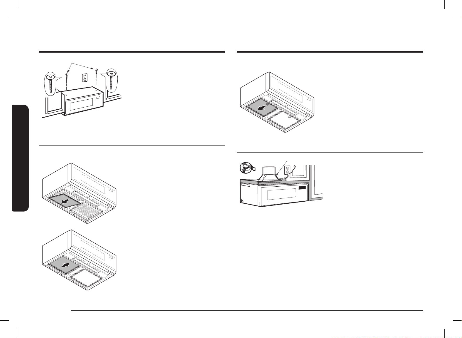
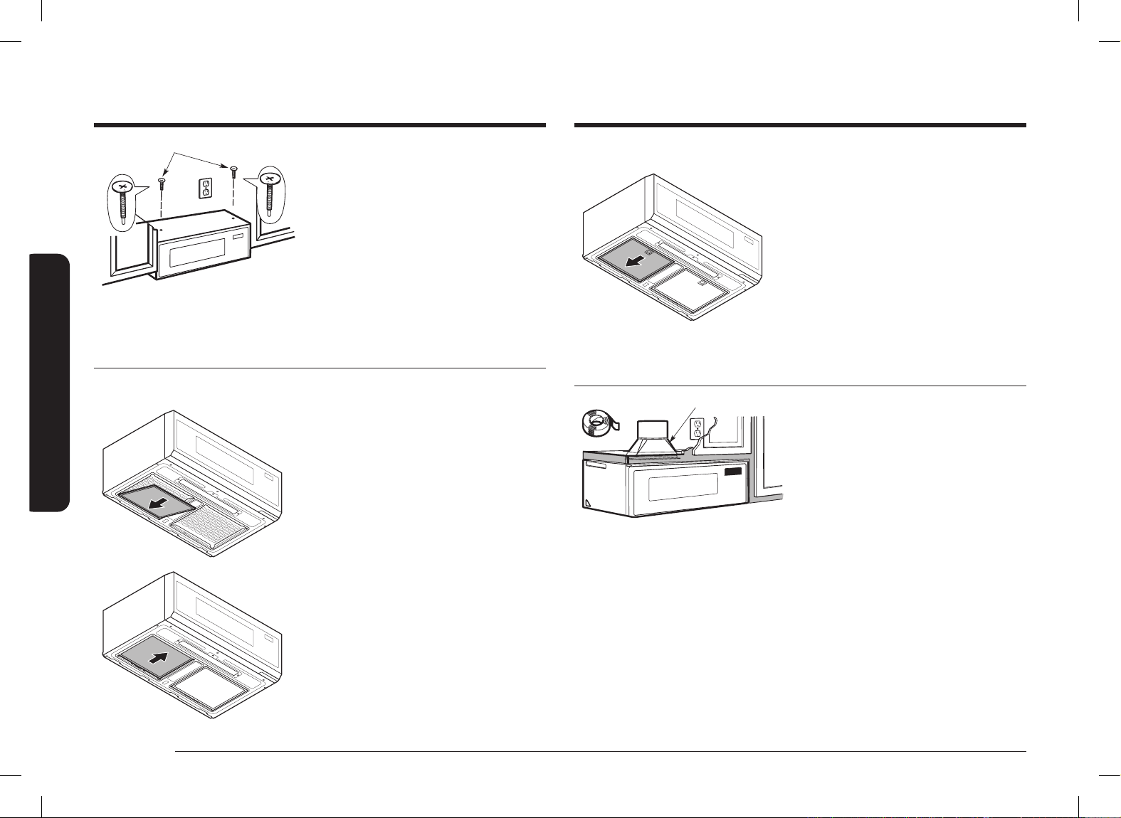
E2. Grease Filter assembly method
1. Push the Grease Filter backward and
insert the Grease Filter until atness
with bottom surface of products.
F. Connect the ductwork for outside top exhaust
House Duct
House Duct
1. Extend the House Duct down to
connect to the Exhaust Adaptor.
2. Seal the exhaust duct joints using
duct tape.
4. Attach the microwave oven to the
top cabinet.
5. Insert the 2 self-aligning screws
through the cabinet bottom shelf and
ller block into the outer top cabinet
of the unit. Continue to support the
unit until both screws are inserted
and engaged at least two full turns,
then fully tighten all screws until the
unit is secure.
E. Installing the charcoal lters and Grease Filters
E1. Charcoal Filter assembly method
1. Insert the Charcoal Filter from the
back.
2. Raise the front of the Charcoal Filter
until it is at with the bottom, and
then pull it forward to lock it in
place.
Install_ME11A7510DG_AC_DE68-04709B-00_EN+CFR.indb 18Install_ME11A7510DG_AC_DE68-04709B-00_EN+CFR.indb 18 2021-06-16 �� 11:00:532021-06-16 �� 11:00:53
English 19
Step-by-step installation guide
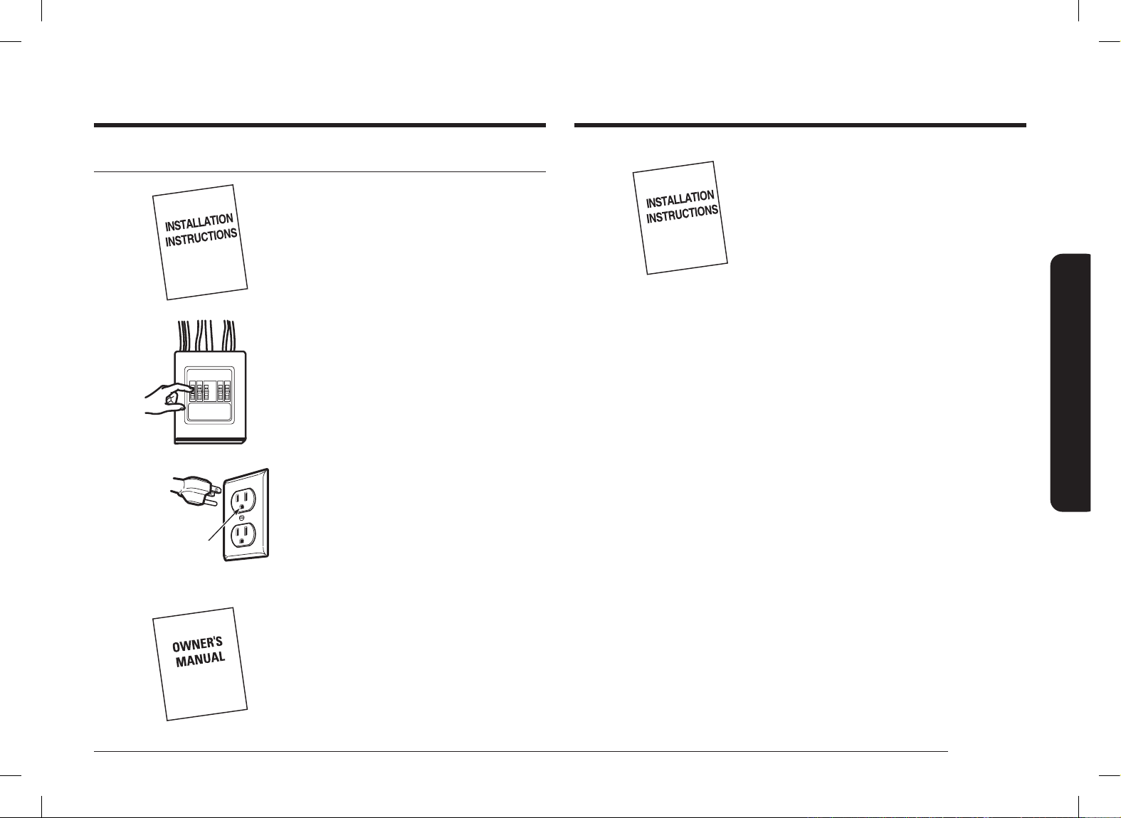
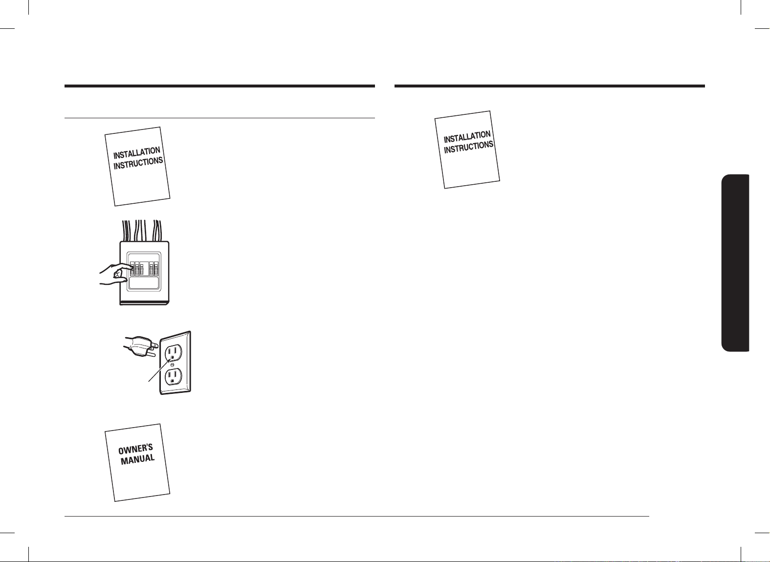
7. Keep installation instructions for the
local inspector’s use.
Step 4. Before you use your microwave
1. Make sure the microwave oven
has been installed according to
instructions.
2. Remove all packing material from the
microwave oven.
3. Install the turntable and ring in the
cavity.
4. Replace the house fuse or turn the
breaker back on.
Insure proper
ground exists
before use.
5. Plug the power cord into a dedicated
15 amp electrical outlet.
6. Read the Owner’s Manual.
Install_ME11A7510DG_AC_DE68-04709B-00_EN+CFR.indb 19Install_ME11A7510DG_AC_DE68-04709B-00_EN+CFR.indb 19 2021-06-16 �� 11:00:532021-06-16 �� 11:00:53
Please be advised that the Samsung warranty does NOT cover service calls to explain product operation, correct improper installation, or perform normal cleaning or
maintenance.
QUESTIONS OR COMMENTS?
COUNTRY CALL OR VISIT US ONLINE AT
U.S.A
Consumer Electronics
1-800-SAMSUNG (726-7864) www.samsung.com/us/support
CANADA 1-800-SAMSUNG (726-7864)
www.samsung.com/ca/support (English)
www.samsung.com/ca_fr/support (French)
DE68-04709B-00
Scan the QR code* or visit
www.samsung.com/spsn
to view our helpful
How-to Videos and Live Shows
* Requires reader to be installed on your
smartphone
Install_ME11A7510DG_AC_DE68-04709B-00_EN+CFR.indb 20Install_ME11A7510DG_AC_DE68-04709B-00_EN+CFR.indb 20 2021-06-16 �� 11:00:532021-06-16 �� 11:00:53

Four à micro-ondes
Manuel d'installation
ME11A7510** / ME11A7710**
Install_ME11A7510DG_AC_DE68-04709B-00_EN+CFR.indb 1Install_ME11A7510DG_AC_DE68-04709B-00_EN+CFR.indb 1 2021-06-16 �� 11:00:542021-06-16 �� 11:00:54
2 Français
AVANT DE COMMENCER
AVANT DE COMMENCER
Table des matières
AVANT DE COMMENCER 2
Informations générales 3
Consignes de sécurité importantes 3
Exigences électriques 3
Échappement de hotte 4
Dommages - Expédition/Installation 6
Pièces incluses avec le produit 6
Outils nécessaires 7
Espace de montage 7
Guide d'installation étape par étape 9
Étape 1 : Emplacement de la plaque de xation 9
Étape 2 : Types de ventilation (sélectionnez A, B ou C) 12
Étape 3 : Installation 15
Étape 4 : Avant d’utiliser votre four micro-ondes 19
AVANT DE COMMENCER
À PROPOS DE CE MANUEL
LISEZ ENTIÈREMENT ET ATTENTIVEMENT CES INSTRUCTIONS.
Important
• Conservez ces instructions d’installation an que la personne chargée du
contrôle local puisse s’y reporter.
• Conservez précieusement ce manuel en vue du passage éventuel d'un technicien
en cas de réparation.
Remarque importante destinée à l'installateur
Assurez-vous de laisser ces instructions à l'utilisateur.
Remarque importante destinée à l'utilisateur
Conservez ces instructions avec votre manuel d’utilisation pour référence future.
Niveau de compétences
L'installation de cet appareil nécessite des connaissances mécaniques et électriques
de base.
L'installateur est responsable de toute mauvaise installation
La défaillance du produit due à une mauvaise installation n’est pas
couverte par la garantie
Install_ME11A7510DG_AC_DE68-04709B-00_EN+CFR.indb 2Install_ME11A7510DG_AC_DE68-04709B-00_EN+CFR.indb 2 2021-06-16 �� 11:00:542021-06-16 �� 11:00:54

Français 3
Informations générales
Informations générales
CONSIGNES DE SÉCURITÉ IMPORTANTES
Cet appareil nécessite une prise tripolaire reliée à la terre. L’installateur doit
effectuer un contrôle de continuité de terre sur le boîtier de prise de courant avant
de commencer l’installation pour s’assurer que le boîtier de prise est correctement
mis à la terre. Si ce n'est pas le cas, ou si la prise ne répond pas aux exigences
indiquées en matière de raccordement électrique (dans la section EXIGENCES EN
MATIÈRE DE RACCORDEMENT ÉLECTRIQUE), faites appel à un électricien qualié
pour corriger les défaillances.
ATTENTION
Pour votre sécurité personnelle, retirez le fusible de la
maison ou ouvrez le disjoncteur avant de commencer
l’installation pour éviter des blessures graves ou
mortelles par électrocution.
ATTENTION
• pour votre sécurité, la surface de xation doit être capable de le poids du
meuble, en plus des 69 livres de l'appareil et des charges pouvant aller jusqu'à
50 livres, soit un poids total de 119 livres.
• Pour des raisons de sécurité personnelle, n’installez pas ce produit dans des
armoires congurées en îlot ou en péninsule. Le four à micro-ondes doit être
monté À LA FOIS sur une armoire supérieure ET sur un mur.
REMARQUE
Pour une installation plus facile et pour des raisons de sécurité personnelle, nous
recommandons que l’installation de ce produit se fasse à deux.
IMPORTANT – LISEZ ATTENTIVEMENT CE MANUEL. POUR VOTRE
SÉCURITÉ, CETAPPAREIL DOIT ÊTRE CORRECTEMENT MISÀ LA
TERRE AFIN D'ÉVITER TOUT RISQUED'ÉLECTROCUTION
Assurez-vous
que le four est
correctement
mis à la terre
avant de
l'utiliser.
Le cordon d'alimentation de cet appareil est équipé d'une
prise tripolaire (mise à la terre) correspondant à la prise
murale tripolaire standard (mise à la terre) an de réduire
le risque d'électrocution.
Faites vérier la prise murale et le circuit par un électricien qualié an de vous
assurer que la prise est correctement mise à la terre.
Si vous possédez une prise murale standard à deux broches, il est très important de
la faire remplacer par une prise murale à trois broches correctement mise à la terre,
installée par un électricien qualié.
NE COUPEZ, NE DÉFORMEZ NI NE RETIREZ JAMAIS LES BROCHES DE LA PRISE DU
CORDON D'ALIMENTATION. N'UTILISEZ PAS DE RALLONGE.
EXIGENCES ÉLECTRIQUES
La valeur nominale du produit est de 120 volts CA, 60 Hertz, 14,5 ampères et
1,7 kilowatt. Cet appareil doit être relié à un circuit d'alimentation doté de la tension
et de la fréquence appropriées. La taille des ls doit être conforme aux exigences
du Code électrique national ou du code local en vigueur pour le régime nominal en
kilowatts. Le cordon d’alimentation et la che doivent être reliés à une prise simple
séparée reliée à la terre à circuit de dérivation entre 15 et 20 A. La prise doit être
placée dans le meuble situé au dessus du four à micro-ondes. La prise et le circuit
d'alimentation doivent être installés par un électricien qualié et conformément au
Code électrique national ou au code local en vigueur.
Install_ME11A7510DG_AC_DE68-04709B-00_EN+CFR.indb 3Install_ME11A7510DG_AC_DE68-04709B-00_EN+CFR.indb 3 2021-06-16 �� 11:00:552021-06-16 �� 11:00:55
4 Français
Informations générales
Informations générales
SYSTÈME D'ÉVACUATION PAR L'ARRIÈRE (EXEMPLE UNIQUEMENT)
Le tableau suivant contient un type d'installation de conduits possible.
COMPOSANTS DE
L'ÉVACUATION
LONGUEUR
ÉQUIVALENTE
x
NOMBRE
UTILISÉ
=
LONGUEUR
ÉQUIVALENTE
Chaperon
mural
40 pi. x (1) = 40 pi.
3 pi. Conduit
droit
(3¼ x 10 po
rectangulaire)
3 pi. x (1) = 3 pi.
Coude de 90° 10 pi. x (2) = 20 pi.
Les longueurs équivalentes des composants du
système d'évacuation sont basées sur des essais
réels et reètent les exigences en matière de
performance de ventilation avec n'importe quel
type de hotte.
Longueur
totale
= 63 pi.
REMARQUE
Pour l'évacuation par l'arrière, veillez à aligner l'évacuation sur l'espace situé entre
les montants ou préparez le mur lors de sa construction en ménageant un espace
entre les montants du mur an de disposer l'évacuation.
ÉCHAPPEMENT DE HOTTE
REMARQUE
les deux prochaines pages ne vous concernent que si vous souhaitez utiliser un
système d'évacuation de l'air. Si vous souhaitez que la circulation de l'air se fasse en
circuit fermé, passez à la page 12.
SYSTÈME D'ÉVACUATION PAR LE HAUT (EXEMPLE UNIQUEMENT)
Le tableau suivant contient un type d'installation de conduits possible.
COMPOSANTS DE
L'ÉVACUATION
LONGUEUR
ÉQUIVALENTE
x
NOMBRE
UTILISÉ
=
LONGUEUR
ÉQUIVALENTE
Chaperon de
toit
24 pi. x (1) = 24 t.
12 pi. Conduit
droit
(6 po rond)
12 pi. x (1) = 12 pi.
Adaptateur
rectangulaire
circulaire*
5 pi. x (1) = 5 pi.
Les longueurs équivalentes des composants du
système d'évacuation sont basées sur des essais
réels et reètent les exigences en matière de
performance de ventilation avec n'importe quel
type de hotte.
Longueur
totale
= 41 pi.
IMPORTANT :
si un adaptateur rectangulaire-circulaire est utilisé, les coins inférieurs du registre
devront être coupés à l'aide de cisailles an de le xer et de permettre au registre
de bouger librement.
Install_ME11A7510DG_AC_DE68-04709B-00_EN+CFR.indb 4Install_ME11A7510DG_AC_DE68-04709B-00_EN+CFR.indb 4 2021-06-16 �� 11:00:552021-06-16 �� 11:00:55
Français 5
Informations générales
COMPOSANTS DE
L'ÉVACUATION
LONGUEUR
ÉQUIVALENTE
x
NOMBRE
UTILISÉ
=
LONGUEUR
ÉQUIVALENTE
Adaptateur
rectangulaire
circulaire*
5 pi. x ( ) = pi.
Chaperon
mural
40 pi. x ( ) = pi.
Coude de 90 ° 10 pi. x ( ) = pi.
Coude de 45 ° 5 pi. x ( ) = pi.
Coude de 90 ° 25 pi. x ( ) = pi.
Coude de 45 ° 5 pi. x ( ) = pi.
Chaperon de
toit
24 pi. x ( ) = pi.
Conduit droit
6 rond ou
3¼ x 10 po
rectangulaire
1 pi. x ( ) = pi.
Total des conduits = pi.
*IMPORTANT: si un adaptateur rectangulaire-circulaire est utilisé, les
coins inférieurs du registre devront être coupés à l'aide
de cisailles an de le xer et de permettre au registre
de bouger librement.
Les longueurs équivalentes des composants du système
d'évacuation sont basées sur des essais réels et reètent
les exigences en matière de performance de ventilation
avec n'importe quel type de hotte.
REMARQUE
Si vous devez installer des conduits, notez que la longueur totale des conduits
rectangulaires de 3¼ x 10po ou ronds de 6po de diamètre ne doit pas dépasser
140pi équivalents.
La ventilation extérieure nécessite un SYSTÈME D'ÉVACUATION DE LA HOTTE. Lisez
attentivement ce qui suit.
REMARQUE
Il est important que la ventilation soit installée en utilisant le chemin le plus
direct et avec le moins de coudes possible. Cela garantit une ventilation dégagée
de l’échappement et aide à prévenir les blocages. Assurez-vous également que
les registres oscillent librement et que rien ne bloque les conduits.
Raccord d’échappement :
L’évacuation de la hotte a été conçue pour s’accoupler avec un conduit rectangulaire
standard de 3¼ x 10 po.
Si un conduit rond est requis, un adaptateur de transition rectangulaire à rond doit
être utilisé. N’utilisez pas un conduit de moins de 6 po de diamètre.
Longueur maximale du conduit :
Pour une circulation d’air satisfaisante, la longueur totale du conduit rectangulaire de
3¼ x 10 po ou rond de 6 po de diamètre ne doit pas dépasser 140 pi équivalents.
Les coudes, transitions, chapeaux de mur et de toit, etc. présentent une résistance
supplémentaire au ux d’air et sont équivalents à une section de conduit droit qui
est plus longue que leur taille physique réelle. Lors du calcul de la longueur totale du
conduit, ajoutez les longueurs équivalentes de toutes les transitions et adaptateurs
plus la longueur de toutes les sections de conduit droites. Le tableau ci-dessous vous
montre comment calculer la longueur équivalente totale des conduits en utilisant la
longueur équivalente en pieds de certains conduits typiques.
Install_ME11A7510DG_AC_DE68-04709B-00_EN+CFR.indb 5Install_ME11A7510DG_AC_DE68-04709B-00_EN+CFR.indb 5 2021-06-16 �� 11:00:552021-06-16 �� 11:00:55
6 Français
Informations générales
Informations générales
PIÈCES SUPPLÉMENTAIRES
PIÈCE QUANTITÉ
TOP CABINET TEMPLATE
REAR WALL TEMPLATE
Gabarit du meuble haut 1
TOP CABINET TEMPLATE
REAR WALL TEMPLATE
Gabarit pour mur arrière 1
Instructions d’installation 1
Template
INSTALLATION
INSTRUCTIONS
Adaptateur du système
d'évacuation
1
Emballé séparément
Filtres à graisse
2
Emballé séparément
Filtres au charbon
2
Couvercle d’aération - Droit 2
Couvercle d’aération - Gauche 1
DOMMAGES EXPÉDITION/INSTALLATION
• Si l'appareil est endommagé lors du transport, retournez-le au magasin dans
lequel il a été acheté an qu'il soit réparé ou remplacé.
• Si l'appareil est endommagé par l'utilisateur, sa réparation ou son remplacement
lui incombe.
• Si l'appareil est endommagé par l'installateur (autre que l'utilisateur), un accord
devra être trouvé entre l'utilisateur et l'installateur en vue d'une réparation ou
d'un remplacement.
PIÈCES INCLUSES AVEC LE PRODUIT
MATÉRIEL
PIÈCE QUANTITÉ
Template
INSTALLATION
INSTRUCTIONS
Vis à bois 1
Template
INSTALLATION
INSTRUCTIONS
Boulons à ailettes
(et écrous à oreilles)
2
Autoalignement
Vis à métal|
Avec supporter
2
L'appareil est livré avec un sachet contenant le matériel d'installation. Vériez que
vous disposez de toutes ces pièces.
REMARQUE
Si l’épaisseur du meuble est supérieure à 1 po,
retirez le supporter.
Install_ME11A7510DG_AC_DE68-04709B-00_EN+CFR.indb 6Install_ME11A7510DG_AC_DE68-04709B-00_EN+CFR.indb 6 2021-06-16 �� 11:00:562021-06-16 �� 11:00:56
Français 7
Informations générales
ESPACE DE MONTAGE
10
11
/16 po
30 po
5 po
24
1
/5 po
Le bord inférieur de
l’armoire doit être à
24
1
/
5
po ou plus de la
surface de cuisson.
Dosseret
12 po max.
REMARQUE
• L’espace entre les armoires doit être de 30 po de large et libre d’obstructions.
• Ce four à micro-ondes est conçu pour une installation sur des cuisinières jusqu’à
36 po de large.
• Si vous souhaitez utiliser un système de ventilation pour le four micro-ondes,
reportez-vous à la partie Système d'évacuation de la hotte pour la préparation
du conduit d'évacuation.
• Lors de l'installation du four micro-ondes sous un meuble plat et lisse, respectez
les instructions gurant sur le gabarit du meuble haut pour la distance
d'isolement du cordon d'alimentation.
• La profondeur maximale du meuble au-dessus et à côté de l’unité est de 12 po.
• Les dimensions indiquées sont celles minimales nécessaires pour le montage
du four micro-ondes. Les codes locaux et l'utilisation pratique de la cuisinière
peuvent nécessiter un espace supérieur aux 13,5 po indiqués entre la cuisinière
et la partie inférieure du four micro-ondes.
OUTILS NÉCESSAIRES
Tournevis cruciforme
n°1 et n°2
Crayon Règle ou mètre à
ruban et règle plate
Équerre de
charpentier
(facultatif)
Cisailles (pour la
coupe du registre si
nécessaire)
Ciseaux (pour la
coupe du gabarit si
nécessaire)
Perceuse électrique
avec mèches de
3
/
16
po,
1
/
2
po et
5
/
8
po
Cales ou morceaux
de bois, pour
l'espacement du
meuble haut si
nécessaire (utilisé
pour l'installation
de meubles
bas encastrés
uniquement)
Gants Scie (scie sauteuse,
scie-cloche ou scie à
guichet)
Détecteur de
montant ou marteau
(facultatif)
Lunettes de
protection
Niveau Ruban adhésif en
toile et ruban-cache
5 po
Install_ME11A7510DG_AC_DE68-04709B-00_EN+CFR.indb 7Install_ME11A7510DG_AC_DE68-04709B-00_EN+CFR.indb 7 2021-06-16 �� 11:00:562021-06-16 �� 11:00:56
8 Français
Informations générales
Informations générales
DIMENSIONS DU PRODUIT
46
11
/
16
po
(1185,9 mm)
avec plaque de support
29
7
/
8
po
(758,8 mm)
10
11
/
16
po
(272,0 mm)
19
3
/
16
po
(486,7 mm)
avec plaque de
support
Install_ME11A7510DG_AC_DE68-04709B-00_EN+CFR.indb 8Install_ME11A7510DG_AC_DE68-04709B-00_EN+CFR.indb 8 2021-06-16 �� 11:00:572021-06-16 �� 11:00:57
Français 9
Guide d'installation étape par étape
B. Détection des montants
Centre
Montants
1. Recherchez les montants en utilisant
l'une des méthodes suivantes :
A. À l’aide d’un détecteur de clous
– un appareil magnétique qui
localise les clous.
OU
B. Utilisez un marteau pour taper
légèrement sur la surface de
montage jusqu’à ce que vous
entendiez un son solide. Cela
indique l'emplacement d'un
montant.
2. Après avoir localisé le ou les
montants, localisez le centre du
montant en sondant le mur avec un
petit clou pour trouver les bords du
montant. Puis tracez un repère au
centre entre des arêtes. Le centre des
montants adjacents doit être situé à
16 ou 24 po de ce repère.
3. Tracez un trait vertical à partir du
centre des montants.
LE FOUR MICRO-ONDES DOIT ÊTRE FIXÉ À AU MOINS UN DES MONTANTS.
Guide d'installation étape par étape
Étape 1 : Emplacement de la plaque de xation
A. Retrait du four micro-ondes du carton/retrait de la plaque de xation
Carton
Polystyrène
Plaque de xation
Vis
Vis
1. Retirez les consignes
d'installation, l'adaptateur
du système d'évacuation,
les ltres, le plateau en
verre et le sachet contenant
le matériel. Ne retirez pas
la mousse de polystyrène
protégeant l'avant du four.
2. Pliez les 4 rabats du carton
contre ses côtés. Retournez
avec précaution le four
et le carton. Le four doit
reposer sur la mousse de
polystyrène.
3. Tirez le carton vers le haut.
4. Retirez et jetez les sacs
en plastique de manière
appropriée.
5. Retirez les 2 vis de la plaque
de xation. Cette plaque
est utilisée comme gabarit
du mur du fond et pour le
montage.
REMARQUE
Conservez les deux vis. Vous
devrez réinsérer les vis dans
leurs emplacements d’origine
après avoir retiré la plaque de
montage.
Install_ME11A7510DG_AC_DE68-04709B-00_EN+CFR.indb 9Install_ME11A7510DG_AC_DE68-04709B-00_EN+CFR.indb 9 2021-06-16 �� 11:00:572021-06-16 �� 11:00:57
10 Français
Guide d'installation étape par étape
Guide d'installation étape par étapeGuide d'installation étape par étape
C. Détermination de l’emplacement de la plaque murale sous le meuble
C
L
Au moins 30 po
Position de la plaque – sous une armoire à
fond plat.
Tracez un trait vertical sur le mur du fond,
au centre de l’espace de 30 po de large.
Fixez le gabarit du fond au mur an que
la partie supérieure du gabarit touche la
partie inférieure du meuble et que le trait
central du gabarit soit aligné avec la ligne
que vous avez tracée sur le mur.
`
i
Plate position – beneath recessed bottom
cabinet with front overhang
Tracez une ligne
horizontale an
de marquer la
distance dont la
partie intérieure
du débord frontal
descend sous le
meuble.
24
1
/5 po
Position de la plaque - sous une armoire
inférieure encastrée avec un surplomb
avant.
Tracez un trait vertical sur le mur du fond,
au centre de l’espace de 30 po de large.
Tracez une deuxième ligne horizontale sur
le mur situé sous le meuble an de marquer
la distance dont la partie intérieure du
débord frontal descend sous le meuble.
Fixez le gabarit du fond au mur an que la
partie supérieure du gabarit touche le bas
de la ligne horizontale et que le trait central
du gabarit soit aligné avec la ligne verticale.
C
L
24
1
/5 po
Position de la plaque - sous un fond
d’armoire encastré encadré.
Tracez un trait vertical sur le mur du fond,
au centre de l’espace de 30 po de large.
Fixez le gabarit du fond au mur an que
la partie supérieure du gabarit touche la
partie inférieure du cadre du meuble et que
le trait central du gabarit soit aligné avec la
ligne que vous avez tracée sur le mur.
Si le meuble sur lequel vous souhaitez xer l’appareil comporte des ornements
décoratifs, ces derniers risquent de gêner l’installation. Retirez ces ornements pour
assurer une installation et une mise à niveau correctes du four.
IL EST TRÈS IMPORTANT QUE LE FOUR MICROONDES SOIT À NIVEAU.
Utilisez un niveau pour vous assurer que le plancher du meuble est bien à
horizontale.
Install_ME11A7510DG_AC_DE68-04709B-00_EN+CFR.indb 10Install_ME11A7510DG_AC_DE68-04709B-00_EN+CFR.indb 10 2021-06-16 �� 11:00:572021-06-16 �� 11:00:57

Français 11
Guide d'installation étape par étape
1. Tracez ensuite une ligne horizontale juste en dessous du gabarit du mur.
2. Percez des trous de
5
/8 po pour les boulons à ailettes à 2 emplacements (trou A,
trou B) comme indiqué sur l’illustration ci-dessus. Si l’emplacement d’un trou est
aligné sur un montant, percez un trou de
3
/16 po en vue de la pose d’une vis à
bois. Les boulons à ailettes ne peuvent être utilisés pour xer la plaque murale
à un montant.
REMARQUE
NE POSEZ PAS ENCORE LA PLAQUE À CETTE ÉTAPE DU MONTAGE.
D. Alignement de la plaque murale
F. DÉCOUPE D’ÉVACUATION
HORIZONTALE
DÉCOUPEZ UN TROU DANS LE MUR APPIÈRE POUR L’ADAPTATEUR D’ÉVACUATION
Ebarbez le modele de parol arriere en suivant les pointilles.
Localisez et marquez d’un repère l’emplacement des trous afin que
ceux-ci soient alignés sur les trous de la plaque de fixation.
IMPORTANT:
LOCALISEZ AU MOINS UN GOUJON DE CHAQUE COTE DE L’AXE MEDIAN.
MARQUEZ L’EMPLACEMENT DE DEUX BOULONS A AILETTES
SUPPLEMENTAIRES SITURS A EGALE DISTANCE DANS LA
ZONE DE LA PLAQUE DE FIXATION.
IL EST RECOMMANDÉ D’INSTALLER LES BOULONS DANS LES TROUS A, B ET C.
L’EMPLACEMENT PEUT ÊTRE MODIFIÉ EN FONCTION DES CIRCONSTANCES MAIS
IL EST RECOMMANDÉ DE LES INSTALLER À PROXIMITÉ DES TROIS TROUS MENTIONNÉS.
GABARIT POUR MUR ARRIÈRE
Localisez et marquez d’un repère l’emplacement des trous afin que
ceux-ci soient alignés sur les trous de la plaque de fixation.
IMPORTANT:
LOCALISEZ AU MOINS UN GOUJON DE CHAQUE COTE DE L’AXE MEDIAN.
MARQUEZ L’EMPLACEMENT DE DEUX BOULONS A AILETTES
SUPPLEMENTAIRES SITURS A EGALE DISTANCE DANS LA
ZONE DE LA PLAQUE DE FIXATION.
IL EST RECOMMANDÉ D’INSTALLER LES BOULONS DANS LES TROUS A, B ET C.
L’EMPLACEMENT PEUT ÊTRE MODIFIÉ EN FONCTION DES CIRCONSTANCES MAIS
IL EST RECOMMANDÉ DE LES INSTALLER À PROXIMITÉ DES TROIS TROUS MENTIONNÉS.
Ebarbez le modele de parol arriere en suivant les pointilles.
REMARQUE: IL EST TRÈS IMPORTANT DE
LIRE ET DE SUIVRE LES DIRECTIVES
D’INSTALLATION AVANT D’UTILISER CE
GABARIT POUR MUR ARRIÈRE.
Ce modèle de paroi arrière permet de placer la plaque
de fixation inférieure et de localiser la sortie d’air horizontale.
1. Utilisez un niveau pour vous assurer que le modèle est correctement positionné.
2. Localisez et marquez d’un repère au moins un goujon à droite ou à gauche de l’axe médian.
REMARQUE:
Utilisez au moins une vis à bois et
fixez-la solidement dans un goujon afin que le montage
ainsi formé supporte le poids du micro-ondes. Localisez
deux emplacements supplémentaires situés à égale
distance en vue de la pose des boulons à ailettes fournis
avec l’appareil.
3. Precez des trous aux emplacements signalés.
Arrivé au goujon, percez un trou de 3/16” en vue de la pose des vis à bois.
Pour les trous non alignés sur un goujon, percez-en d’autres de 5/8” en vue de
la pose des boulons à ailettes.
REMARQUE:
NE POSEZ PAS LA PLAQUE DE FIXATION A CETTE ETAPE DU MONTAGE.
4. Enlevez le gabarit du mur arrière.
5. Reportez-vous aux consignes d’installation afin de connaître vos conditions d’installation.
Turn over for English.
Imprimé en Malaisie
DE68-04707B-00
MISE EN GARDE - SI L’ADAPTATEUR D’ÉVACUATION EST PLACÉ À L’EXTÉEIRUR
DES DIMENSIONS RECOMMANDÉES, L’AIR CHARGÉ DE GRAISSE
SERA RELÂCHÉ DANS LA STRUCTURE DE LA MAISON
LARGEUR MINIMALE DE 30 PO REQUISE
Tracez ensuite un trait horizontal juste en
dessous du gabarit du mur.
Tracez un trait vertical sur le mur
du fond, au centre de l’espace de le
armoire situé au dessus.
Trait horizontal
Zone E
Encoches sur
le trait central
Trou A
Trou B
Trou C
Trait horizontal
ATTENTION
portez des gants car les bords de la plaque sont très tranchants.
3. Les trous A et B sont à l’intérieur de la zone E. Si aucun de ces trous ne s’aligne
avec un montant, trouvez un montant dans la zone E qui s’aligne avec un cercle
de trous dans la zone E, puis percez un trou de 3/16 po pour vis à bois. Vous
devez utiliser au moins une vis à bois et la xer solidement dans un montant
an que le montage ainsi formé supporte le poids du four à micro-ondes.
Mettez la plaque de montage de côté.
Install_ME11A7510DG_AC_DE68-04709B-00_EN+CFR.indb 11Install_ME11A7510DG_AC_DE68-04709B-00_EN+CFR.indb 11 2021-06-16 �� 11:00:582021-06-16 �� 11:00:58

12 Français
Guide d'installation étape par étape
Guide d'installation étape par étapeGuide d'installation étape par étape
Étape 2 : Types de ventilation (sélectionnez A, B ou C)
Ce four à micro-ondes est compatible avec les trois systèmes de ventilation suivants :
A. Système d'évacuation par le haut
(conduit vertical)
B. Circulation de l'air en circuit fermé
(sans conduit et sans évents)
Support
C. Système d'évacuation par l'arrière
(conduit horizontal)
REMARQUE
Ce micro-ondes est expédié assemblé pour la recirculation. Un adaptateur du
système d'évacuation est livré assemblé et xé à la cale supérieure. Sélectionnez
le système de ventilation adapté à votre installation et reportez-vous à la section
correspondante.
A. Système d'évacuation par le haut (conduit vertical)
A1. ADAPTATION DU PANNEAU DE PROTECTION POUR L’ADAPTATEUR
D’ÉCHAPPEMENT
Panneau de couverture
Panneau
arrière
1. Retirez 1 vis du panneau de
couverture et retirez le panneau de
couverture.
2. Retirez 1 vis du panneau arrière.
3. Assemblez le panneau de couverture
en le glissant de haut en bas et la vis
qui a été retirée du panneau arrière.
Install_ME11A7510DG_AC_DE68-04709B-00_EN+CFR.indb 12Install_ME11A7510DG_AC_DE68-04709B-00_EN+CFR.indb 12 2021-06-16 �� 11:00:582021-06-16 �� 11:00:58
Français 13
Guide d'installation étape par étape
Support
Les supports marqués ne doivent pas
avoir de trous d’aération.
REMARQUE
Vous devez vérier l’image du support en
fonction du type de ventilation à la page
12.
REMARQUE
Appliquer A1 et A2 de manière égale.
B. Circulation de l’air en circuit fermé (sans conduit et sans évents)
B1. Adaptation du PANNEAU DE COUVERTURE pour la recirculation
Panneau de couverture
Panneau
arrière
1. Assurez-vous que le panneau
de couverture est assemblé
correctement. (Assemblage supérieur)
A2. MONTAGE DU REGISTRE
Registre
1. Retirez le ruban xant le registre.
2. Assemblez le registre en le glissant de
l’arrière vers l’avant jusqu’à l’arrêt.
REMARQUE
Assurez-vous que les registres oscillent
librement.
House Duct
Conduit de maison
REMARQUE
• Vous devez xer le conduit de
l'habitation à l'adaptateur du système
d'évacuation après avoir terminé
l'installation.
• Vous devez sceller les joints du
conduit d’échappement à l’aide de
ruban adhésif.
Install_ME11A7510DG_AC_DE68-04709B-00_EN+CFR.indb 13Install_ME11A7510DG_AC_DE68-04709B-00_EN+CFR.indb 13 2021-06-16 �� 11:00:582021-06-16 �� 11:00:58
14 Français
Guide d'installation étape par étape
Guide d'installation étape par étape
Plaque
8EA
Après avoir retiré les plaques
2. Coupez 8 zones pour retirer les
plaquettes à l’aide d’une pince.
Les supports marqués ne doivent pas
avoir de trous d'aération.
REMARQUE
Vous devez vérier l'image du support en
fonction du type de ventilation à la page
12.
Les supports marqués doivent avoir
des trous d’aération.
REMARQUE
• L’adaptateur d’échappement avec le
registre n’est pas nécessaire pour
le type à recirculation. Vous pouvez
toutefois les conserver en vue d'une
utilisation ultérieure éventuelle.
• Vous devez vérier l'image du
support en fonction du type de
ventilation à la page 12.
C. Système d'évacuation par l'arrière (conduit horizontal)
C1. Adaptation du PANNEAU DE COUVERTURE pour échappement arrière extérieur
1. Assurez-vous que le panneau
de couverture est assemblé
correctement. (Assemblage supérieur)
Install_ME11A7510DG_AC_DE68-04709B-00_EN+CFR.indb 14Install_ME11A7510DG_AC_DE68-04709B-00_EN+CFR.indb 14 2021-06-16 �� 11:00:582021-06-16 �� 11:00:58

Français 15
Guide d'installation étape par étape
Dim. Comparaison
13
5
3
4
6
1
2
6
1
4
9
1
4
(235mm)
Côté gauche
Côté droit
Mur
arrière
Il faut maintenir
une distance de
jusqu'au mur arrière.
9
1
4
(235mm)
Il faut maintenir
une distance de
jusqu'au mur arrière.
Installations pour décharge à travers le toit
Découper cette partie du fond du placard supérieur
si la décharge se fait à travers le toit.
IMPORTANT : Lire les instructions d'installation fournies avec
l'ensemble four à micro-ondes/hotte. Suivre les
instructions dans la section "Préparation du
placard supérieur" des instructions d'installation.
Gabarit pour placard supérieur
Axe central
9
1
4
(235mm)
Il faut maintenir
une distance de
jusqu'au mur arrière.
13
3
32
(332.4mm)
13
3
32
(332.4mm)
1
1
2
REMARQUE :
Installer une bague pour
cordon d'alimentation,
autour du trou percé dans
un placard en métal.
Trou pour cordon
d'alimentation
1
15
32
(37.3mm)
Mur
arrière
1
2
1
2
3
4
4
FENTE DE DÉCOUPE
POUR LES CABINETS
À FOND PLAT LISSE
UNIQUEMENT
CORDON
D'ALIMENTATION
11
7
16
(290.75mm)
REMARQUE
Après avoir placé les vis dans les trous D et E,
vériez les dimensions.
6
31
64
(164.5mm)
Vissez la longueur d’exposition
(du fond du placard à l’extrémité du boulon)
sans l'option de Supporter.
28
32
1
26
32
~
(46mm) (22mm)
Vissez la longueur d’exposition
(du fond du placard à l’extrémité du boulon)
lorsque vous utilisez l’option Supporter.
28
32
1
30
32
~
(49mm) (22mm)
DE68-04708B-00
Découpez d’abord ce trou
avant de découper l’ouverture
de la ventilation du toit
3
1
/
2
po
(88,7 mm)
1
27
/
32
po
(47 mm)
9
1
/
4
po
(235 mm)
1
15
/
32
po
(37,3 mm)
26
3
/
16
po
(664,8 mm)
1
27
/
32
po
(47 mm)
3. Retirez le ruban xant le registre.
4. Assemblez le registre en glissant du
haut vers le bas jusqu’à l’arrêt.
REMARQUE
Assurez-vous que les registres oscillent
librement.
Étape 3 : Installation
PRÉSENTATION DE L'INSTALLATION
F. CUT OUT FOR HORIZONTAL
OUTSIDE EXHAUSE
REAR WALL TEMPLATE
A. Préparez le mur arrière (pour
l’évacuation arrière extérieure/
conduit horizontal uniquement)
B. Fixation de la plaque murale
C. Préparez l’armoire du dessus
D. Montage du four micro-ondes
E. Raccordez les conduits (pour
l’évacuation supérieure extérieure/
conduit vertical uniquement)
Install_ME11A7510DG_AC_DE68-04709B-00_EN+CFR.indb 15Install_ME11A7510DG_AC_DE68-04709B-00_EN+CFR.indb 15 2021-06-16 �� 11:00:592021-06-16 �� 11:00:59
16 Français
Guide d'installation étape par étape
Guide d'installation étape par étape
Extrémité du boulon
Plaque de
xation
Boulon à
ailettes
Mur
Ailettes
3. Placez la plaque de montage contre
le mur, pincez les ailes de chaque
bascule ensemble, puis insérez les
ailes à bascule de chaque bascule
dans et à travers les trous du mur.
REMARQUE
avant de serrer les boulons à ailettes et
la vis à bois, assurez-vous que la partie
inférieure de la plaque de xation est
alignée sur le trait horizontal inférieur
du gabarit du mur du fond ; assurez-vous
également que la plaque est correctement
centrée sous le meuble.
ATTENTION
veillez à ne pas vous pincer les doigts
entre l’arrière de la plaque et le mur.
4. Serrez tous les boulons. Retirez
la plaque du mur pour faciliter
l’opération. Serrez la vis.
C. Utilisez le gabarit de l’armoire supérieure pour préparer
l’armoire du dessus
Vous devez percer des trous pour les vis de xation supérieure et un trou de
diamètre sufsamment important pour y faire passer le cordon d’alimentation.
• Lisez les instructions gurant sur le
GABARIT DU MEUBLE HAUT.
• Collez-le sous le plancher du meuble
haut.
• Percez les trous en respectant les
instructions gurant sur le GABARIT
DU MEUBLE HAUT.
ATTENTION
portez des lunettes de sécurité pendant
cette dernière opération.
A. Préparez la paroi arrière pour l’échappement arrière extérieur
Vous devez pratiquer une ouverture dans le mur du fond pour installer le système
d'évacuation.
C
L
• Lisez les instructions relatives au
système d'évacuation par l'arrière
gurant sur le GABARIT DU MUR DU
FOND.
• Fixez le GABARIT DU MUR DU FOND
au mur arrière.
• Pratiquez l'ouverture en respectant
les instructions gurant sur le
GABARIT DU MUR DU FOND.
ATTENTION
Ne pratiquez pas une ouverture dans le
mur du fond si vous souhaitez installer
le four micro-ondes avec une ventilation
sans conduit et sans évents ou à conduit
vertical.
B. Fixation de la plaque murale
Fixez la plaque au mur à l'aide de boulons
à ailettes. Au moins une vis à bois est
nécessaire pour xer la plaque à un
goujon.
1. Retirez les ailettes des boulons.
2. Insérez les boulons dans la plaque
de xation via les trous pour cloison
sèche, puis remettez les ailettes
de telle sorte que ¾ po du boulon
dépasse l'ailette.
Install_ME11A7510DG_AC_DE68-04709B-00_EN+CFR.indb 16Install_ME11A7510DG_AC_DE68-04709B-00_EN+CFR.indb 16 2021-06-16 �� 11:00:592021-06-16 �� 11:00:59

Français 17
Guide d'installation étape par étape
Équivalent à la
profondeur de
l’évidement de
l’armoire
Étagère inférieure d’armoire
Haut du four micro-ondes
Avant du meuble
Bloc de remplissage
Vis
autocentreuse
1. Soulevez le microondes, inclinez-le
vers l'avant et faites correspondre les
encoches situées à l'arrière et en bas
avec les quatre pattes inférieures de
la plaque de xation.
2. Faites pivoter la partie frontale du
four vers le haut contre le dessous du
meuble.
3. Insérez une vis autocentreuse dans
le trou central du meuble haut. Fixez
temporairement le four en faisant
effectuer à la vis au moins deux tours
complets après l’engagement des
lets. (Elle sera complètement serrée
ultérieurement.) Assurez-vous de
conserver le cordon d’alimentation
correctement connecté. Attention à ne
pas coincer le cordon, en particulier
au moment où vous montez le four à
eur contre le plancher du meuble.
Épaisseur de l’armoire
1
/16
~
15
/16 po
Supporter
REMARQUE
Si l’épaisseur de l’armoire
est inférieure à 1 po,
utilisez un supporter.
1
~
2 po
REMARQUE
Si l’épaisseur du meuble
est supérieure à 1 po,
retirez le supporter de la
vis d’autoalignement.
REMARQUE
La vis autocentreuse peut être installée jusqu’à une profondeur de 1
15
/
16
po (49 mm).
D. Montage du four micro-ondes
POUR PLUS DE FACILITÉ ET DE SÉCURITÉ
LORS DE L’INSTALLATION DE L’APPAREIL,
DEUX PERSONNES SONT NÉCESSAIRES.
IMPORTANT: évitez de saisir ou
d’accrocher la poignée du
four pendant l’installation.
REMARQUE
• si votre meuble est en métal, placez
la rondelle en nylon dans le trou du
cordon d’alimentation an d’éviter de
couper ce dernier.
• des cales sont nécessaires pour le
montage de cette unité sous un
meuble encastré ou avec débord
frontal. (Voir page 10.)
IMPORTANT: les dommages causés à
l’habillage du meuble qui
pourraient survenir à cause
du serrage excessif des
vis provoqué par la non-
utilisation de cales n’est pas
couvert par la garantie.
IMPORTANT: Veillez à ne pas endommager
le verre de la lampe
inférieure pendant la
manipulation.
REMARQUE
lors du montage du four, faites passer le cordon d’alimentation dans le trou pratiqué
dans le plancher du meuble haut. Gardez-le bien serré tout au long des étapes 1 à 3.
Ne pincez pas le cordon et ne soulevez pas le four en tirant sur le cordon.
Install_ME11A7510DG_AC_DE68-04709B-00_EN+CFR.indb 17Install_ME11A7510DG_AC_DE68-04709B-00_EN+CFR.indb 17 2021-06-16 �� 11:01:002021-06-16 �� 11:01:00
18 Français
Guide d'installation étape par étape
Guide d'installation étape par étape
E2. Méthode d’assemblage du ltre à graisse
1. Poussez le ltre à graisse vers
l’arrière et insérez le ltre à graisse
jusqu’à ce qu’il soit plat avec la
surface inférieure des produits.
F. Connectez le réseau de conduits pour l’échappement supérieur
extérieur
House Duct
Conduit de maison
1. Tirez le conduit de la cuisine vers le
bas pour le relier à l’adaptateur du
système d’évacuation.
2. Scellez les joints du conduit du
système d’évacuation à l’aide d’un
ruban adhésif en toile.
4. Fixez le four micro-ondes sur le
meuble haut.
5. Insérez 2 vis autocentreuses à travers
le fond du meuble et des cales dans
les trous extérieurs du meuble haut
de l’unité. Continuez le soutien l’unité
jusqu’à ce que les deux vis soient
insérées et engagées d’au moins
deux tours complets, puis serrez
complètement toutes les vis jusqu’à ce
que l’unité soit sécurisée.
E. Installation des ltres à charbon et des ltres à graisse
E1. Méthode d’assemblage du ltre à charbon
1. Insérez le ltre à charbon par
l’arrière.
2. Soulevez l’avant du ltre à charbon
jusqu’à ce qu’il repose à plat sur le
fond, puis tirez-le vers l’avant pour
l’immobiliser.
Install_ME11A7510DG_AC_DE68-04709B-00_EN+CFR.indb 18Install_ME11A7510DG_AC_DE68-04709B-00_EN+CFR.indb 18 2021-06-16 �� 11:01:002021-06-16 �� 11:01:00
Français 19
Guide d'installation étape par étape
7. Conservez précieusement ces
instructions d'installation an que la
personne chargée du contrôle local
puisse s'y reporter.
Étape 4 : Avant d’utiliser votre four micro-ondes
1. Assurez-vous que le four micro-ondes
a été installé conformément aux
instructions.
2. Retirez tout élément d'emballage du
four micro-ondes.
3. Installez le plateau tournant et la bague
dans la cavité.
4. Remplacez le fusible ou remettez le
disjoncteur sous tension.
Assurez-vous
que le four est
correctement mis
à la terre avant de
l'utiliser.
5. Branchez le cordon d'alimentation sur
une prise dédiée de 15 A.
6. Lisez le manuel d'utilisation.
Install_ME11A7510DG_AC_DE68-04709B-00_EN+CFR.indb 19Install_ME11A7510DG_AC_DE68-04709B-00_EN+CFR.indb 19 2021-06-16 �� 11:01:002021-06-16 �� 11:01:00

Scannez le code QR* ou rendez-vous sur le site
www.samsung.com/spsn pour voir nos
vidéos et démonstrations en direct
d’utilisation.
* Requiert l’installation d’un lecteur sur votre smartphone
Veuillez noter que la garantie Samsung n'inclut pas les déplacements du service après-vente pour expliquer le fonctionnement de l'appareil, corriger une installation non correcte
ou exécuter des travaux de nettoyage ou d'entretien réguliers.
UNE QUESTION ? UN COMMENTAIRE ?
PAYS N° DE TÉLÉPHONE SITE INTERNET
U.S.A
Consumer Electronics
1-800-SAMSUNG (726-7864) www.samsung.com/us/support
CANADA 1-800-SAMSUNG (726-7864)
www.samsung.com/ca/support (English)
www.samsung.com/ca_fr/support (French)
DE68-04709B-00
Install_ME11A7510DG_AC_DE68-04709B-00_EN+CFR.indb 20Install_ME11A7510DG_AC_DE68-04709B-00_EN+CFR.indb 20 2021-06-16 �� 11:01:002021-06-16 �� 11:01:00