Loading ...
Loading ...
Loading ...
English 11
Step-by-step installation guide
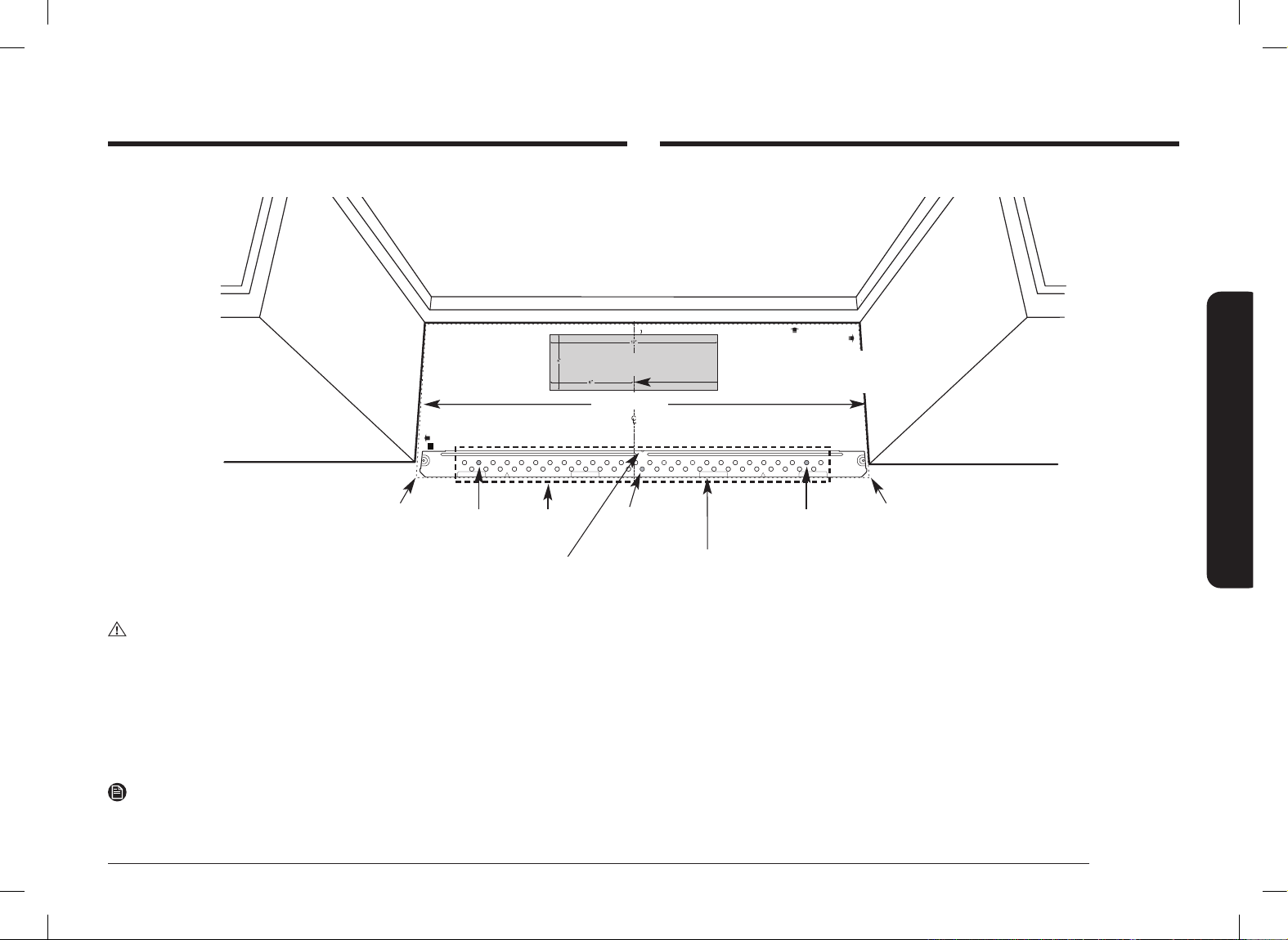
1. Draw a horizontal line on the wall at the bottom of the “Rear Wall Template”.
2. Drill
5
/8˝ holes for toggle bolts in 2 locations (Hole A, Hole B) as shown in the
illustration above. If the location of a hole lines up with a stud, drill a
3
/16˝ hole
for a wood screw. You cannot use a toggle bolt to attach the wall plate to a
stud.
NOTE
DO NOT MOUNT THE PLATE AT THIS TIME.
D. Aligning the wall plate
NOTE: IT IS VERY IMPORTANT TO
READ AND FOLLOW THE DIRECTIONS
IN THE INSTALLATION INSTRUCTIONS
BEFORE PROCEEDING WITH THIS
REAR WALL TEMPLATE.
This Rear Wall Template serves to position the bottom
mounting plate and to locate the horizontal exhaust outlet
1. Use a level to check that the template is positioned accurately.
2. Locate and mark at least one stud on the left or right side of the centerline.
NOTE:
It is important to use at least one wood screw mounted rmly in a stud to support
the weight of the microwave. Mark two additional, evenly spaced locations for
the supplied toggle bolts.
3. Drill holes in the marked locations. Where there is a stud, drill a 3/16” hole for wood screws,
for holes that do not line up with a stud, drill 5/8” holes for toggle bolts
NOTE:
DO NOT INSTALL THE MOUNTING PLATE AT THIS TIME.
4. Remove the template from the rear wall.
5. Review the Installation Instruction book for your installation situation.
Français au verso.
3/8
"
TO EDGE
F. CUT OUT FOR HORIZONTAL
OUTSIDE EXHAUSE
CUT HOLE THROUGH REAR WALL FOR EXHAUST ADAPTOR
REAR WALL TEMPLATE
CAUTION - IF EXHAUST ADAPTOR IS POSITIONED OUTSIDE
RECOMMENDED DIMENSION, GREASE-LADEN AIR WILL
DISCHARGE INTO HOUSE STRUCTURE.
Locate and mark holes to align with holes in the mounting plate.
IMPORTANT:
LOCATE AT LEAST ONE STUD ON EITHER SIDE OF THE CENTERLINE.
MARK THE LOCATION FOR 2 ADDITIONAL, EVENLY SPACED TOGGLE
BOLTS IN THE MOUNTING PLATE AREA.
IT IS RECOMMENDED TO INSTALL BOLTS IN A, B, AND C HOLES. THE LOCATION
MAY BE SUBJECT TO CHANGE ACCORDING TO CIRCUMSTANCES BUT IT IS
RECOMMENDABLE TO INSTALL THEM NEAR THE THREE HOLES MENTIONED.
Trim the rear wall template along the dotted line.
Trim the rear wall template along the dotted line.
Locate and mark holes to align with holes in the mounting plate.
IMPORTANT:
LOCATE AT LEAST ONE STUD ON EITHER SIDE OF THE CENTERLINE.
MARK THE LOCATION FOR 2 ADDITIONAL, EVENLY SPACED TOGGLE
BOLTS IN THE MOUNTING PLATE AREA.
IT IS RECOMMENDED TO INSTALL BOLTS IN A, B, AND C HOLES. THE LOCATION
MAY BE SUBJECT TO CHANGE ACCORDING TO CIRCUMSTANCES BUT IT IS
RECOMMENDABLE TO INSTALL THEM NEAR THE THREE HOLES MENTIONED.
Printed in Malaysia
DE68-04707B-00
30
"
MINIMUM WIDTH REQUIRED
Draw a horizontal line on the wall along the
bottom of the “Rear Wall Template”.
Draw a vertical line on the
wall to mark the center of
the cabinet above.
Horizontal Line
Area E
Centerline
notches
Hole A
Hole B
Hole C
Horizontal Line
CAUTION
Wear gloves to avoid cutting ngers on sharp edges.
3. Holes A and B are inside area E. If none of these holes line up with a stud,
nd a stud in area E that lines up with a hole circle in Area E, and then drill
a
3
/16˝ hole into it for a wood screw. You must have at least one wood screw
mounted rmly into a stud to support the weight of the microwave. Set the
mounting plate aside.
Install_ME11A7510DG_AC_DE68-04709B-00_EN+CFR.indb 11Install_ME11A7510DG_AC_DE68-04709B-00_EN+CFR.indb 11 2021-06-16 �� 11:00:512021-06-16 �� 11:00:51
Loading ...
Loading ...
Loading ...