
Loading ...
Loading ...
Loading ...
12 English
ShowMatch
TM
DeltaQ
TM
Array Rigging Frames - Installation Guide
Installation
pro.Bose.com
Connect Pull Back Bracket to Full-Range Module
Attach the ShowMatch Pull Back Bracket (SMPULL) to the bottom full-range array module to provide a third
structural attachment point when creating an array with a more extreme downard tilt.
The pull back bracket provides three rigging points along the rear to connect a pullback cable or the
Transition Bracket Accessory (SMSTK). For more information about the Transition Bar Accessory, see pro.
Bose.com.
When connecting a pullback cable, it is recommended to use either the center rigging point, both side rigging
points, or all three rigging points. The primary suspension points of the array frame should be as close as
possible to the center of gravity of the array to minimize the tension load in the pullback cable.
Use Bose Modeler software or the Bose Array Tool to determine if the pull back bracket is required and to
confirm that the pullback angle and working load is within acceptable safe limits. For more information on
Modeler and the Bose Array Tool, see pro.Bose.com.
Note: The Pull Back Bracket is not intended to provide primary structural support for the entire array!
To connect the pull back bracket to a full-range array module:
1. Assemble the array on the Array Frame or T-Bar Array Frame by following the instructions in this manual
and on pro.Bose.com.
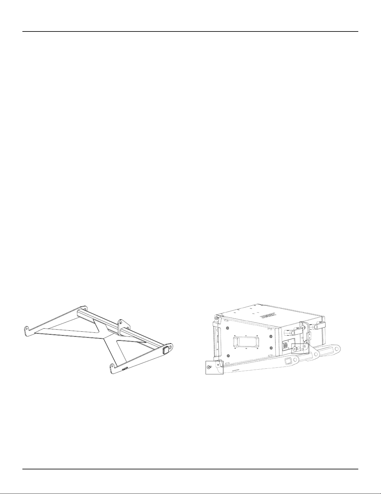
2. Position the pull back bracket with the connection tabs facing up (toward the array). See Fig. 5.
3. Align the three connection tabs on the pull back bracket with the three connection points on the bottom
full-range array module (two in front, one in the rear center).
4. Insert two front pins (one on each side), then insert one rear pin to secure pull back bracket to module.
See Fig. 6.
5. Attach pullback cable(s) to the bracket using the included shackles.
6. Connect field wiring, test loudspeaker operation, and then elevate assembly to final operating position.
7. Adjust length of pullback cable attached to the pullback bracket as required for desired array tilt angle.
Fig 5. Pullback bar positioned with connection tabs facing up Fig 6. Insert pins to attach pull back bracket to module
Loading ...
Loading ...
Loading ...