ShowMatch
TM
DeltaQ
TM
Array Rigging Frames
Installation and Safety Guidelines
Instrucciones de Instalacion y de Seguridad
Installation et Instructions de Sécurité
Installations- und Sicherheitshinweise
ShowMatch
TM
DeltaQ
TM
Array Rigging Frames - Important Safety Instructions
Important Safety Instructions
pro.Bose.com
2 English
Please read this installation guide carefully and save it for future reference.
This product is intended for installation by professional installers only! This document is intended to provide professional installers with basic installation
and safety guidelines for this product in typical fixed-installation or portable-system applications. Please read this document and all safety warnings before
attempting installation.
WARNINGS:
• All Bose
®
products must be installed in accordance with local, state, federal and industry regulations. It is the installer’s responsibility to ensure
installation of the loudspeakers and mounting system is performed in accordance with all applicable codes, including local building codes and
regulations. Consult the local authority having jurisdiction before installing this product.
• Unsafe mounting or overhead suspension of any heavy load can result in serious injury or death, and property damage. It is the responsibility
of the installer to evaluate the reliability of any mounting method used for their application. Only professional installers with the knowledge of
proper hardware and safe mounting techniques should attempt to install any loudspeaker overhead.
CAUTION:
• Installed loudspeaker arrays require regular inspection and routine maintenance to ensure proper function and
safe operation. Inspect mounting hardware and attachments for signs of corrosion, bending or any other condition that may decrease the
structural integrity. Immediately replace worn or damaged components.
• Do not make unauthorized alterations to this product; doing so may compromise safety, regulatory compliance, system performance, and may
void the warranty.
NOTE: Always use Bose Modeler
®
or Bose Array Tool software to confirm safe working load limits with exact array configurations, pitch angles, and connection
points.
Guidelines for Installation and Setup of ShowMatch Array Module Loudspeakers
The installation information contained in this document is only a general guideline and cannot, as such, represent all requirements and precautions.
Accordingly, anyone using this material assumes all liability and is expressly responsible for the safety of all loudspeaker array designs and mounting
configurations applied in practice.
• Prior to the installation or portable-system setup of any overhead loudspeaker, a licensed professional engineer must approve the location and method
of attachment to the building structure or support-truss structure and confirm they are consistent with all building codes and regulations. Ensure the
mounting surface and the method of attaching the loudspeaker system to the surface is capable of supporting the total weight of the system. A safety
factor of 10:1 is recommended.
• Obtain all mounting system components from reputable manufacturers. Select a mounting system appropriate for your loudspeaker system and its
intended application. We recommend Bose mounting accessories when available. A licensed professional engineer must review the design and fabrication
of any custom mounting hardware.
• Do not suspend loudspeaker using handles as attachment points. Handles are NOT designed for load bearing!
• Use a safety cable, separately attached to the cabinet, at a point not in common with the load bearing attachment points of the mounting system to the
loudspeaker. This is recommended even if not required by local regulation. Consult a licensed professional engineer or a rigging professional for proper
design and installation.
• Do not under any circumstances climb the array.
Instrucciones de Seguridad Importantes
Lea detenidamente esta guía de instalación y consérvela para consultarla en el futuro.
Este producto está diseñado para que solo instaladores profesionales realicen su instalación. Este documento está diseñado para proveer las pautas de
seguridad e instalación básicas a los instaladores profesionales de este producto en aplicaciones de sistema portátil e instalación fija comunes. Lea este
documento y todas las advertencias de seguridad antes de comenzar la instalación.
ADVERTENCIAS:
• Todos los productos Bose
®
deben instalarse según las reglamentaciones locales, estatales, federales y del sector. Es responsabilidad del
instalador garantizar que la instalación del sistema de soporte y los altavoces se realice conforme a los códigos aplicables, incluidos los códigos
y las reglamentaciones de construcción locales. Consulte a la autoridad local competente antes de instalar este producto.
• El montaje inseguro o la suspensión en alturas de cualquier carga pesada puede provocar lesiones graves o la muerte, además de daños a
la propiedad. Es responsabilidad del instalador evaluar la fiabilidad de cualquier método de montaje utilizado para su aplicación. Solo los
instaladores profesionales con el conocimiento de los componentes físicos adecuados y las técnicas de montaje seguro deberían intentar
instalar cualquier altavoz en altura.
PRECAUCIÓN:
• Se deben inspeccionar regularmente los arreglos instalados de altavoz, además de realizarles mantenimiento de rutina con el propósito de
garantizar su funcionamiento adecuado y
operación segura. Revise los accesorios y los componentes físicos para instalación, y busque signos de corrosión, torcimiento o cualquier otra
condición que pueda disminuir la integridad estructural. Sustituya inmediatamente los componentes desgastados o dañados.
• Solo realice alteraciones autorizadas a este producto. De lo contrario, podría comprometer la seguridad, el cumplimiento de las
reglamentaciones y el rendimiento del sistema; además, podría anular la garantía.
Nota: Utilice siempre el software Modeler® o “Bose Array Tool” para confirmar los límites de seguridad de carga de trabajo con cada configuración del arreglo,
ángulos de inclinación y los puntos de conexión.
Pautas de instalación y configuración de los altavoces de arreglo modular ShowMatch
La información de instalación incluida en este documento solo corresponde a pautas generales y, como tal, no puede representar todos los requisitos ni todas
las precauciones. Por lo tanto, todo aquel que utilice este material asume toda la responsabilidad y es expresamente responsable de todos los diseños de
arreglo y las configuraciones de montaje del altavoz realizadas en la práctica.
• Antes de la instalación o la configuración del sistema portátil de cualquier altavoz en altura, un ingeniero profesional licenciado debe aprobar la
ubicación y el método de fijación a la estructura del inmueble o a la estructura colgante, y confirmar que sean compatibles con todos los códigos y las
reglamentaciones de construcción. Asegúrese de que la superficie de montaje y el método de fijación a la superficie del sistema de altavoces pueda
soportar el peso total del sistema. Se recomienda un factor de seguridad de 10:1.
• Obtenga todos los componentes de montaje del sistema de fabricantes acreditados. Seleccione un sistema de montaje adecuado para su sistema de
altavoz y su aplicación prevista. Recomendamos que utilice accesorios de montaje de Bose si están disponibles. Un ingeniero profesional licenciado debe
revisar el diseño y la fabricación de todos los componentes físicos personalizados para la instalación.
• No utilice las asas como puntos de fijación para suspender el altavoz. Las asas NO están diseñadas para soportar la carga.
• Utilice un cable de seguridad, unido de forma independiente al gabinete, en un punto distinto del punto de fijación de la carga del sistema de montaje del
altavoz. Esto se recomienda incluso si la reglamentación local no lo requiere. Consulte a un ingeniero profesional licenciado o a profesionales de andamiaje
para realizar un diseño y una instalación adecuados.
• Bajo ninguna circunstancia trepe el arreglo.

Instructions Importantes Relatives à la Sécurité
Français 3
Instructions Importantes Relatives à la Sécurité - ShowMatch
TM
DeltaQ
TM
Array Rigging Frames
pro.Bose.com
Wichtige Sicherheitshinweise
Bitte lesen Sie diese Montageanleitung sorgfältig durch und bewahren Sie sie zum späteren Nachschlagen auf.
Dieses Produkt darf nur von fachkundigen Monteuren installiert werden! Dieses Dokument soll fachkundigen Monteuren grundlegende Installations- und
Sicherheitsrichtlinien für dieses Produkt in mobilen und festinstallierten Anwendungen bieten. Bitte lesen Sie dieses Dokument und alle Sicherheitshinweise vor
der Installation durch.
WARNUNG:
• Alle Produkte von Bose müssen gemäß lokalen und gesetzlichen Vorschriften sowie gemäß allen Branchenbestimmungen installiert werden. Der
Monteur ist dafür verantwortlich, sicherzustellen, dass die Installation der Lautsprecher und der Halterung gemäß allen geltenden Vorschriften
durchgeführt wird, einschließlich örtlicher Bauvorschriften und -bestimmungen. Wenden Sie sich vor der Installation dieses Produkts an die
zuständige abnehmende Behörde.
• Eine unsichere Befestigung schwerer Lasten oder deren Aufhängung über Kopf kann zu schweren oder tödlichen Verletzungen und
Sachschäden führen. Der Monteur ist dafür verantwortlich, die Zuverlässigkeit der für die Anwendung verwendeten Befestigungstechniken zu
prüfen. Nur fachkundige Monteure mit Wissen über sachgemäße Befestigungselemente und sichere Befestigungstechniken sollten Lautsprecher
über Kopf installieren.
VORSICHT:
• Installierte Lautsprecher erfordern regelmäßige Überprüfung und Routinewartung, um die ordnungsgemäße Funktion und den sicheren Betrieb
zu gewährleisten. Überprüfen Sie die Befestigungselemente und das Zubehör auf Anzeichen von Korrosion, Verbiegen oder andere Anzeichen,
die die mechanische Stabilität verringern können. Ersetzen Sie abgenutzte oder beschädigte Teile sofort.
• Keine nicht autorisierten Veränderungen am Produkt vornehmen. Diese können die Sicherheit, die Einhaltung von Richtlinien und die
Systemleistung beeinträchtigen. In diesem Fall kann die Garantie ungültig werden.
Anmerkung: Verwenden Sie immer die Bose Modeler
®
Software oder die “Bose Array Tool” Software, um die sicheren Lastbedingungen (Safe Working Load
Limit) für eine Array-Konfiguration mit gegebenen Neigungswinkeln und Verbindungspunkten zu ermitteln.
Richtlinien für die Montage und Inbetriebnahme von ShowMatch Array Modul Lautsprechern
Die in diesem Dokument enthaltenen Installationsinformationen sind nur eine allgemeine Richtlinie und können daher nicht alle Anforderungen und
Vorsichtsmaßnahmen darstellen. Demgemäß übernimmt jeder, der dieses Material verwendet, die gesamte Haftung und ist ausdrücklich verantwortlich für die
Sicherheit aller Lautsprecher-Array-Designs und deren Montagetechniken, die in der Praxis eingesetzt werden.
• Vor der Installation oder temporären Inbetriebnahme von Lautsprechern über Kopf muss ein zugelassener fachkundiger Techniker den Ort und die Art der
Befestigung an der Gebäude- bzw. Trägerstruktur prüfen und bestätigen, dass diese allen Bauvorschriften und Bestimmungen entspricht. Vergewissern
Sie sich, dass die Befestigungsfläche und die Art und Weise der Befestigung des Lautsprechersystems an der Fläche geeignet ist, das Gesamtgewicht des
Systems zu tragen. Es wird ein Sicherheitsfaktor von 10:1 empfohlen.
• Beschaen Sie sich alle Komponenten der Halterung von zertifizierten Herstellern. Wählen Sie eine Halterung, die für Ihr Lautsprechersystem und die
beabsichtigte Anwendung geeignet ist. Wir empfehlen Befestigungszubehör von Bose, sofern verfügbar. Ein zugelassener fachkundiger Techniker muss die
Auslegung und die Herstellung der benutzerspezifischen Befestigungselemente überprüfen.
• Hängen Sie die Lautsprecher nicht mithilfe von Grien als Befestigungspunkte auf. Grie sind NICHT als Montagepunkte vorgesehen.
• Bringen Sie ein zusätzliches Sicherungsseil an der Box an. Verwenden Sie hierzu nicht die tragenden Befestigungspunkte, die die Halterung mit dem
Lautsprecher verbinden. Wir empfehlen diese Sicherheitsmaßnahme auch dann, wenn diese von den örtlichen Behörden nicht vorgeschrieben ist. Wenden
Sie sich wegen der sachgemäßen Auslegung und Installation an einen zugelassenen fachkundigen Techniker oder ein Fachunternehmen.
• Besteigen Sie unter keinen Umständen das Array.
Consultez attentivement cette notice d’installation et conservez-la pour toute référence future.
L’installation de ce produit doit être eectuée par un technicien professionnel! Ce document à l’intention des installateurs professionnels contient les
directives de pose et de sécurité relatives à ce produit en installation fixe ou dans des applications portables. Veuillez lire ce document, ainsi que l’ensemble
des avertissements de sécurité avant de procéder à l’installation.
AVERTISSEMENTS:
• Tous les produits Bose
®
doivent être installés dans le respect des réglementations professionnelles, locales et nationales. L’installateur est
responsable du respect de tous les codes et règlements locaux et nationaux en vigueur applicables à l’installation et au montage des enceintes.
Consultez les autorités locales compétentes avant d’installer ce produit.
• Tout montage non sécurisé d’une lourde charge peut provoquer des dégâts matériels et des blessures graves, voire la mort. Il en va de
la responsabilité de l’installateur d’évaluer la fiabilité de la méthode de montage utilisée, en fonction de l’application. Seul un installateur
professionnel connaissant les accessoires et techniques de montage adaptés est qualifié pour installer des enceintes suspendues.
ATTENTION:
• Une fois installées, les systèmes d’enceintes doivent faire l’objet d’une inspection et d’un entretien préventif afin d’assurer
un fonctionnement en toute sécurité. Vérifiez que les composants et les points de fixation ne portent pas de traces de corrosion, de
déformations ou autre signe de détérioration de leur intégrité structurelle. Remplacez immédiatement tout composant usé ou endommagé.
• Toute modification non autorisée peut compromettre votre sécurité, le respect des réglementations et le bon fonctionnement de l’appareil, et
en invalidera la garantie.
Note: Toujours utiliser le logiciel Bose Modeler
®
ou «Bose Arras Tool» pour confirmer les limites sécuritaires d’accrochage ainsi que configurations, angles
d’orientation et points de connexion.
Instruction d’installation et de configuration du module d’enceintes ShowMatch
Les directives d’installation contenues dans le présent document ne représentent que des conseils généraux et, à ce titre, ne présentent pas tous les critères et
précautions de rigueur. En conséquence, toute personne utilisant ce document assume seule l’entière responsabilité de la sécurité d’installation de toutes les
enceintes et de la configuration pratique de leur montage.
• Avant l’installation d’un système portable ou d’une enceinte suspendue, il est nécessaire de faire approuver par un professionnel dûment autorisé
l’emplacement et la méthode de fixation à la structure du bâtiment et de lui faire confirmer que cette fixation est conforme au code du bâtiment et aux
réglementations. Il est important de s’assurer que la surface de montage et la méthode de fixation des enceintes à cette surface sont adaptées au poids
total du système. Par sécurité, il est recommandé de respecter un rapport de poids de 10:1.
• Tous les composants du système de montage doivent provenir d’un fabricant de bonne réputation. Le système de montage choisi doit être adapté aux
enceintes et à l’utilisation prévue. Il est recommandé d’utiliser les accessoires de montage Bose disponibles. Faire contrôler par un professionnel qualifié la
conception et la fabrication des accessoires de montage sur mesure.
• Ne pas utiliser les poignées de transport des enceintes comme points de suspension. Ces poignées ne sont pas conçues pour supporter une charge
permanente!
• Fixer un câble de sécurité, attaché séparément au coret de l’enceinte, en un point autre que les points de fixation du système de montage de l’enceinte.
Cette mesure est recommandée, même si elle n’est pas imposée par la réglementation locale. Pour la conception et la réalisation de l’installation, consulter
un professionnel agréé.
• Ne monter sur le système en aucune circonstance.

Contents
pro.Bose.com
4 English
ShowMatch
TM
DeltaQ
TM
Array Rigging Frames - Installation Guide
Introduction
Product Applications ...............................................................................................................................................................................5
Additional Product Information .......................................................................................................................................................... 5
Manufacturer Declaration ......................................................................................................................................................................5
Technical Information
Product Descriptions and Dimensions ............................................................................................................................................6
ShowMatch Array Frame (SMAF) ..............................................................................................................................................6
ShowMatch T-Bar Array Frame (SMAFT) ...............................................................................................................................7
ShowMatch Array Pullback Bracket (SMPULL) ....................................................................................................................8
Installation
Array Rigging ..............................................................................................................................................................................................9
Connect Array Frame or T-Bar Array Frame to Full-Range Module ...................................................................................9
Connect Array Frame to Subwoofer ................................................................................................................................................11
Connect Pull Back Bracket to Full-Range Module ......................................................................................................................12
Additional Resources
Contact Information.................................................................................................................................................................................13
Importer Information .......................................................................................................................................................................13
Limited Warranty ......................................................................................................................................................................................13
Introduction
English 5Installation Guide - ShowMatch
TM
DeltaQ
TM
Array Rigging Frames
pro.Bose.com
Product Applications
Bose® ShowMatch
TM
array frames and rigging accessories are designed for use with ShowMatch DeltaQ
TM
Array loudspeakers (SM5, SM10, and SM20) and ShowMatch DeltaQ Array subwoofers (SMS118).
Not for use with non-ShowMatch loudspeakers.
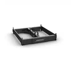
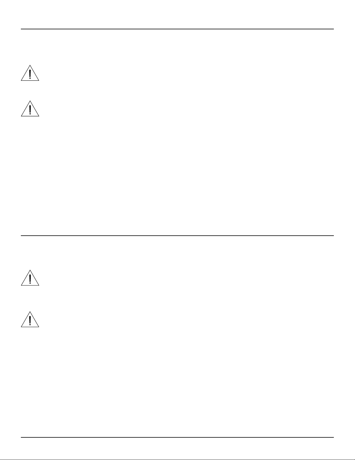
Array Frame
Use the ShowMatch Array Frame (SMAF) to create overhead
suspended arrays that contain subwoofer modules, or to create
ground stack arrays that use any combination of subwoofer modules,
mid/high modules, or both.
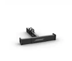
T-Bar Array Frame
Use the ShowMatch T-Bar Array Frame (SMAFT) to create overhead
suspended arrays that contain mid/high modules only.
Do not use the T-bar Array Frame with arrays that contain subwoofer
modules or to create ground stack arrays.
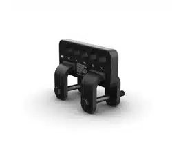
Array Pullback Bracket
Connect the ShowMatch Array Pullback Bracket (SMPULL) to the
bottom full-range array module to provide third-point suspension to
building structure. This allows more extreme downward angle of arrays
than possible from 2-point, gravity-hang suspension.
Additional Product Information
For more information and complete installation instructions for ShowMatch DeltaQ loudspeaker modules and
compatible accessories, refer to the installation guide available at pro.Bose.com. To request a printed copy,
use the phone numbers provided in the Contact Information section of this guide.
Manufacturer Declaration
We hereby declare that the ShowMatch DeltaQ Array loudspeakers and accessories have been designed and
built in compliance with BGV C1 standards and technical specifications. This declaration shall cease to be valid
if alterations are made to the equipment without our prior agreement.
Technical Information
pro.Bose.com
6 English ShowMatch
TM
DeltaQ
TM
Array Rigging Frames - Installation Guide
Product Descriptions and Dimensions
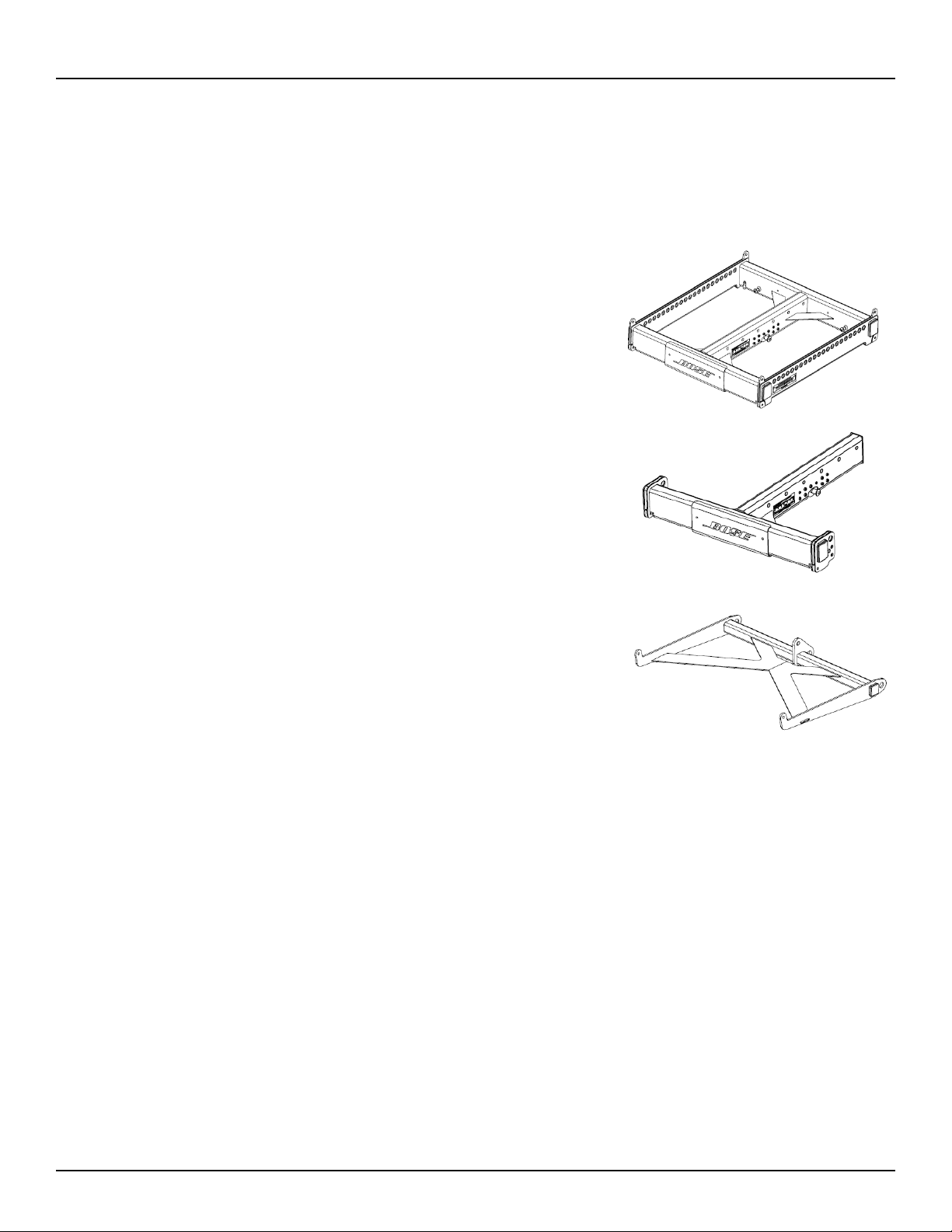
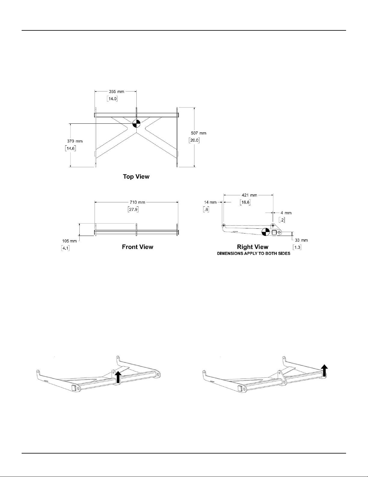
ShowMatch
TM
Array Frame (SMAF)
Product Weight: 83.0 lbs (37.6 kg)
Product weight includes one shackle adapter. Each shackle adapter is 1.5 lbs (0.7 kg).
ShowMatch Array Frame (SMAF)
Center Rail
WLL = 1800 lbs (815 kg)
ShowMatch Array Frame (SMAF)
Side Rail
WLL = 1400 lbs (630 kg)
Single Point, 10:1 Working Load Limit (in accordance with ANSI E1.8-2012)
Installation Guide - ShowMatch
TM
DeltaQ
TM
Array Rigging Frames English 7
Technical Information
pro.Bose.com
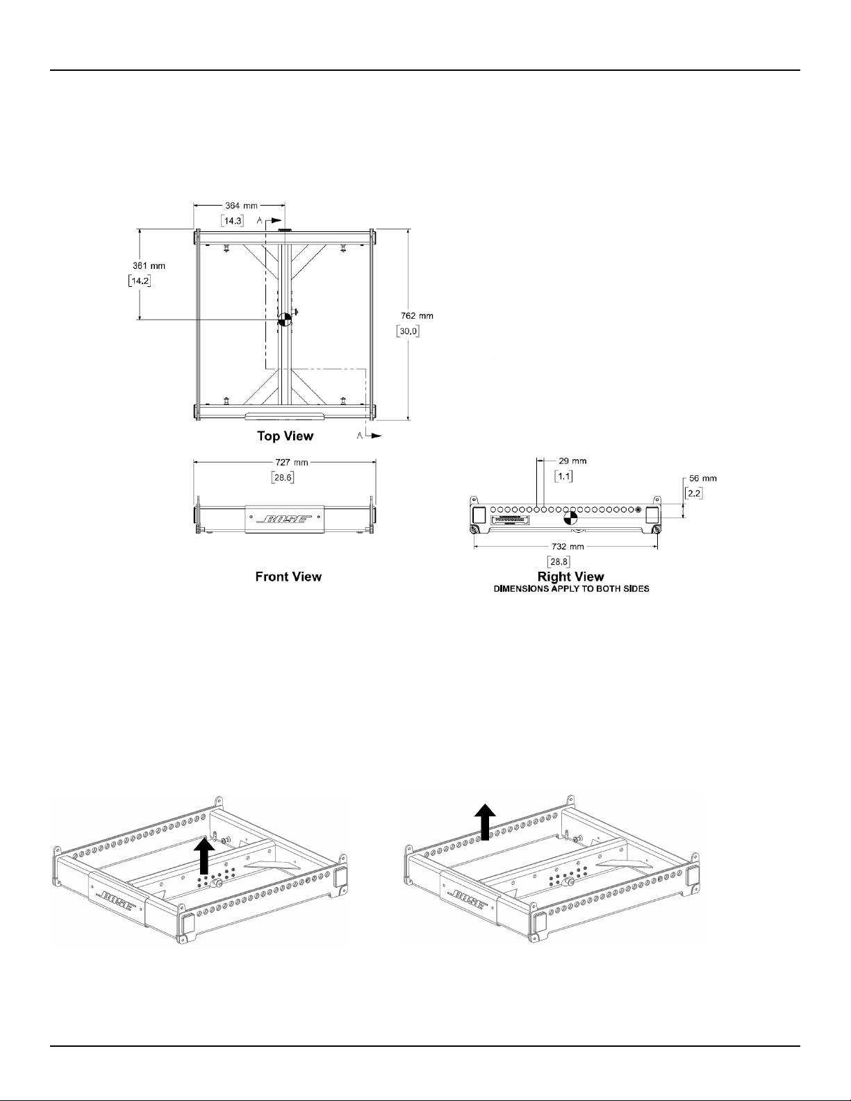
ShowMatch
TM
T-Bar Array Frame (SMAFT)
Product Weight: 40.5 lbs (18.4 kg)
Product weight includes one shackle adapter. Each shackle adapter is 1.5 lbs (0.7 kg).
ShowMatch T-Bar Array Frame (SMAFT)
Center Rail
WLL = 1400 lbs (630 kg)
Single Point, 10:1 Working Load Limit (in accordance with ANSI E1.8-2012)
Technical Information
pro.Bose.com
8 English ShowMatch
TM
DeltaQ
TM
Array Rigging Frames - Installation Guide
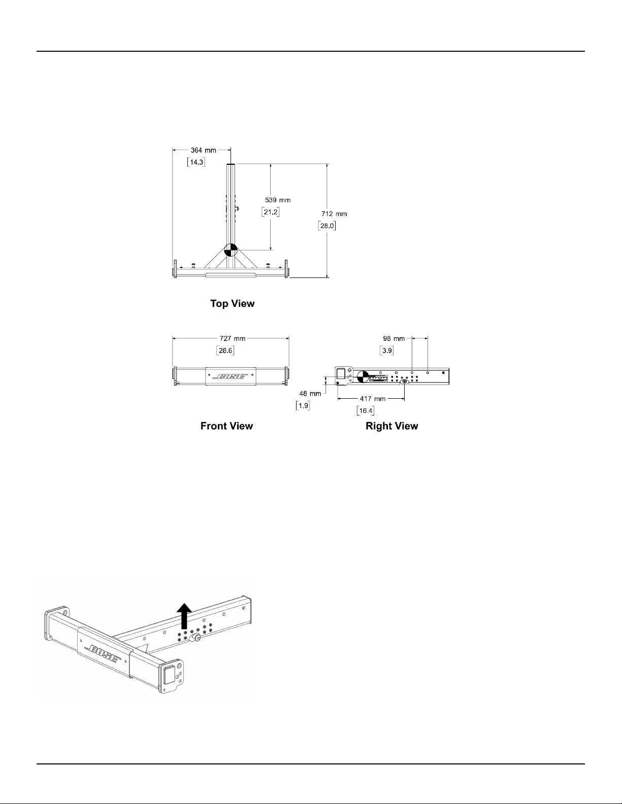
ShowMatch
TM
Array Pullback Bracket (SMPULL)
Product Weight: 15 lbs (18.4 kg)
ShowMatch Array Pullback Bracket
(SMPULL) Center Suspension Point
WLL = 700lbs (315 kg)
ShowMatch Array Pullback Bracket
(SMPULL) Side Suspension Point
WLL = 600 lbs (270 kg)
Single Point, 10:1 Working Load Limit (in accordance with ANSI E1.8-2012)

Installation Guide - ShowMatch
TM
DeltaQ
TM
Array Rigging Frames English 9
Installation
pro.Bose.com
Array Rigging
ShowMatch DeltaQ array loudspeakers are shipped with integrated link-bar rigging hardware. The rigging
system is designed to allow fast setup of typical concert-touring or fixed-installation arrays of up to 24 full-
range or 18 subwoofer modules while maintaining a 10:1 Safety Factor when used with Bose® ShowMatch
Array Frame Rigging Accessories.
Note: Always confirm safe working load limits with exact array configurations, pitch angles, and connection
points using either Bose Modeler® or Bose Array Tool software.
Note: Bose ShowMatch loudspeakers and rigging accessories are intended for installation by professional
installers only!
Note: All lifting operations require two individuals positioned on each side of the loudspeaker.
Refer to pro.Bose.com for additional product installation and setup information.
Connect Array Frame or T-Bar Array Frame to Full-Range Module
The ShowMatch Array Frame (SMAF) contains four connection points for subwoofer modules (all four
corners), and three connection points for full-range modules (two front corners and a center location). Each
side rail provides 21 rigging points, labeled according to the image printed on the frame. The center rail
provides seven rigging points, and is expandable to up to 45 points using the Multipoint Bracket Accessory
(SMAFMP). For more information about the Multipoint Bracket Accessory, see pro.Bose.com.
The ShowMatch T-Bar Array Frame (SMAFT) contains three rigging points for full-range array modules (two
front corners and rear center). The center rail provides seven rigging points, and is expandable to up to 45
points using the Multipoint Bracket Accessory. The T-Bar Array Frame is compatible with full-range modules
(SM5, SM10, and SM20) only. Do not use the T-Bar Array Frame with subwoofer modules (SMS118). To create
an array with subwoofer modules, use the ShowMatch Array Frame.
The Array Frame and the T-Bar Array Frame each include two (2) shackle adapters to attach the frame to
chains or standard shackles, and four (4) Quick Pins to connect an array module to the frame. To create
a narrower array, remove the side end caps and tethered quick pins that are factory-installed on each
loudspeaker module, and use the optional Short Quick Pin Accessory Kit (SMQPS). For more information
about the Short Quick Pin Accessory Kit, see pro.Bose.com.

10 English
ShowMatch
TM
DeltaQ
TM
Array Rigging Frames - Installation Guide
Installation
pro.Bose.com
To connect a ShowMatch Array Frame or T-Bar Array Frame to a full-range loudspeaker module:
1. Use Bose® Modeler® software or the Bose Array Tool to determine appropriate rigging points on array
frames for required aiming angles, and to confirm that array does not exceed load limits of frame. For
more information on Modeler and the Bose Array Tool, see pro.Bose.com.
2. Place array frame directly under chain motors.
3. Attach included frame shackle adapters to array frame at rigging points determined by software.
4. Lower chain motors and attach chains to shackle adapters installed on array frame.
5. Raise array frame to a height slightly greater than that of the first (top) module to be installed.
6. With one person per side, place first module directly under suspended array frame.
7. Raise the links on module: Remove the pins, slide the link switch from the STOW position to the LINK
position, and replace the pins. See Fig. 1.
8. Lower array frame onto first module.
9. Adjust module position to align pin holes of module and frame.
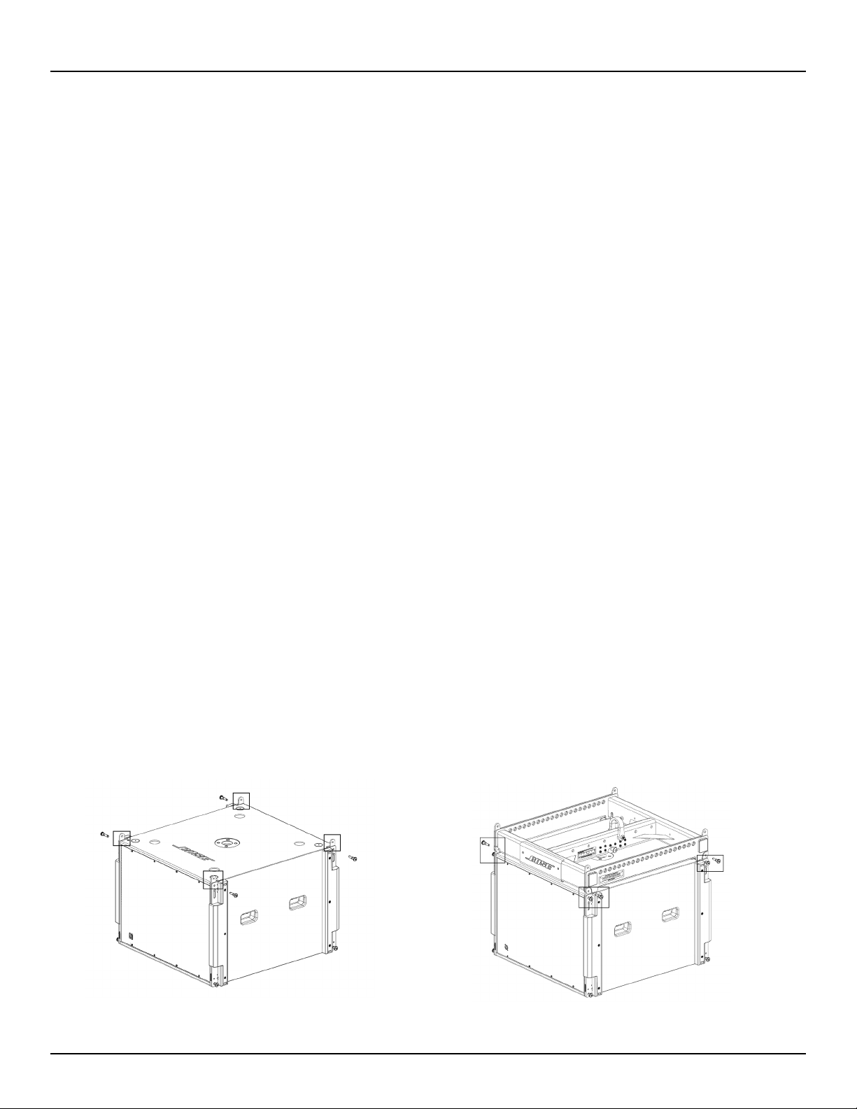
10. Insert two front pins (one on each side), then insert rear center pin to secure module to frame. See Fig. 2.
11. Raise array frame to a height slightly greater than that of the next module.
12. With one person per side, place next module directly under suspended array.
13. Lower array onto next module.
14. Align pin holes of second (bottom) module to pin holes of first (top) module.
15. Insert two front pins (one on each side), then insert rear center pin to secure .
16. Repeat steps to install additional modules in the array. Do not exceed load limits of frame.
17. Connect field wiring, test loudspeaker operation, and then elevate array assembly to final operating
position.
Fig. 1. Raise links on module Fig. 2. Insert pins to attach module to frame
Installation Guide - ShowMatch
TM
DeltaQ
TM
Array Rigging Frames English 11
Installation
pro.Bose.com
Connect Array Frame to Subwoofer
The ShowMatch
TM
Array Frame (SMAF) provides four connection points for SMS118 subwoofers (one in
each corner) and 21 rigging points on each side rail, labeled according to the image printed on the frame.
The center rail provides 7 rigging points, and is expandable to up to 45 points using the Multipoint Bracket
Accessory (SMAFMP).
Note: Subwoofers are compatible with the ShowMatch Array Frame only. Do not use a T-Bar Array Frame
with subwoofer modules.
When flying an array that contains both full-range and subwoofer modules, the subwoofer modules must be
in the top positions of the array.
To connect a ShowMatch Array Frame to a subwoofer:
1. Use Bose® Modeler® software or the Bose Array Tool to determine appropriate rigging points on array
frames for required aiming angles, and to confirm that array does not exceed load limits of frame. For
more information on Modeler and the Bose Array Tool, see pro.Bose.com.
2. Place array frame directly under chain motors.
3. Attach included shackle adapters to array frame at rigging points determined by software.
4. Lower chain motors and attach chains to shackle adapters installed on array frame.
5. Raise array frame to a height slightly greater than that of the subwoofer.
6. With one person per side, place subwoofer directly under suspended array frame.
7. Raise each of the four corner links on the subwoofer by removing the pin, sliding the link switch from the
STOW position to the LINK position, and replacing the pin. See Fig. 3.
8. Lower array frame onto subwoofer.
9. Adjust subwoofer position to align pin holes of module and frame.
10. Insert two front pins (one on each side), then insert two rear pins (one on each side) to secure subwoofer
to frame. See Fig. 4.
11. Raise array frame to a height slightly greater than that of the next module.
12. With one person per side, place next module directly under suspended array.
13. Lower array onto next module.
14. Align links of second (bottom) module to links of first (top) module.
15. Insert two front pins (one on each side), then insert rear center pin to secure bottom module.
16. Repeat steps to install additional modules in the array. Do not exceed load limits of frame.
17. Connect field wiring, test loudspeaker operation, and then elevate array assembly to final operating
position.
Fig. 3. Raise links on subwoofer
Fig. 4. Insert pins to attach subwoofer to frame
12 English
ShowMatch
TM
DeltaQ
TM
Array Rigging Frames - Installation Guide
Installation
pro.Bose.com
Connect Pull Back Bracket to Full-Range Module
Attach the ShowMatch Pull Back Bracket (SMPULL) to the bottom full-range array module to provide a third
structural attachment point when creating an array with a more extreme downard tilt.
The pull back bracket provides three rigging points along the rear to connect a pullback cable or the
Transition Bracket Accessory (SMSTK). For more information about the Transition Bar Accessory, see pro.
Bose.com.
When connecting a pullback cable, it is recommended to use either the center rigging point, both side rigging
points, or all three rigging points. The primary suspension points of the array frame should be as close as
possible to the center of gravity of the array to minimize the tension load in the pullback cable.
Use Bose Modeler software or the Bose Array Tool to determine if the pull back bracket is required and to
confirm that the pullback angle and working load is within acceptable safe limits. For more information on
Modeler and the Bose Array Tool, see pro.Bose.com.
Note: The Pull Back Bracket is not intended to provide primary structural support for the entire array!
To connect the pull back bracket to a full-range array module:
1. Assemble the array on the Array Frame or T-Bar Array Frame by following the instructions in this manual
and on pro.Bose.com.
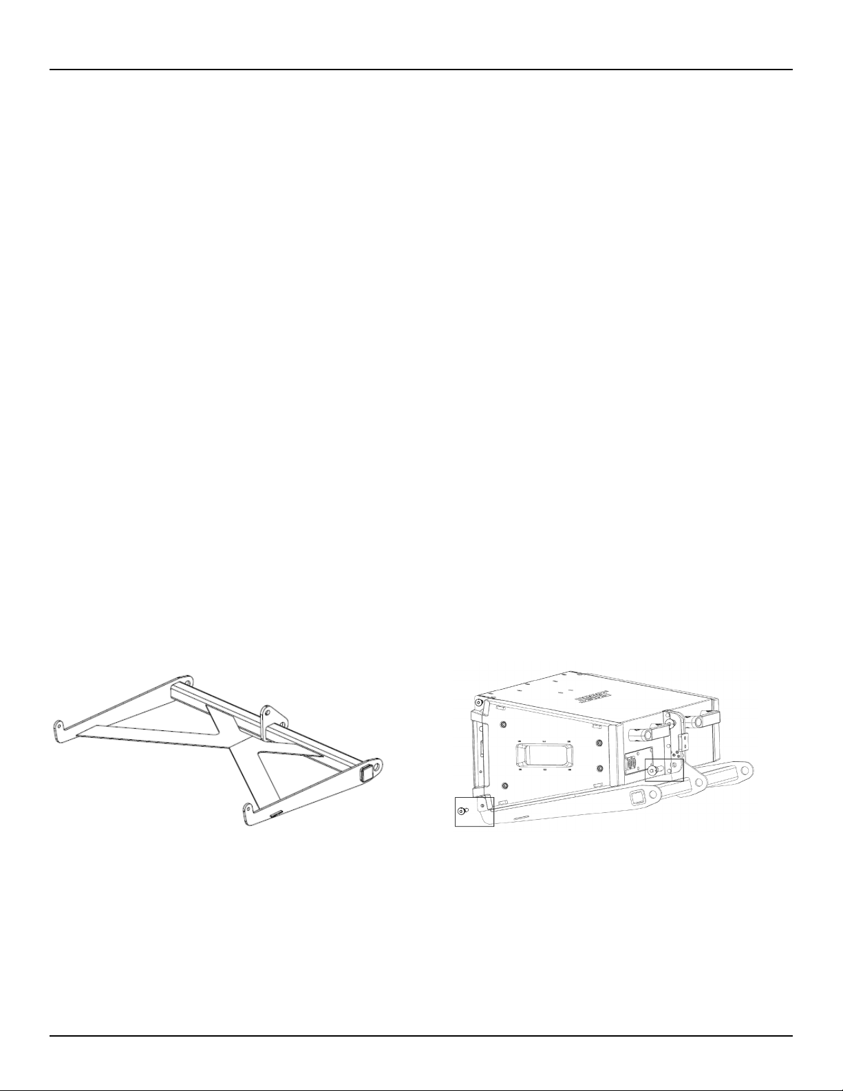
2. Position the pull back bracket with the connection tabs facing up (toward the array). See Fig. 5.
3. Align the three connection tabs on the pull back bracket with the three connection points on the bottom
full-range array module (two in front, one in the rear center).
4. Insert two front pins (one on each side), then insert one rear pin to secure pull back bracket to module.
See Fig. 6.
5. Attach pullback cable(s) to the bracket using the included shackles.
6. Connect field wiring, test loudspeaker operation, and then elevate assembly to final operating position.
7. Adjust length of pullback cable attached to the pullback bracket as required for desired array tilt angle.
Fig 5. Pullback bar positioned with connection tabs facing up Fig 6. Insert pins to attach pull back bracket to module

Installation Guide - ShowMatch
TM
DeltaQ
TM
Array Rigging Frames
English 13
Additional Information
pro.Bose.com
Visit us on the web at pro.Bose.com.
Americas
(USA, Canada, Mexico, Central America, South America)
Bose Corporation
The Mountain
Framingham, MA 01701 USA
Corporate Center: 508-879-7330
Americas Professional Systems,
Technical Support: 800-994-2673
Australia
Bose Pty Limited
Unit 3/2 Holker Street
Newington NSW Australia
61 2 8737 9999
Belgium
Bose N.V. / S.A
Limesweg 2, 03700
Tongeren, Belgium
012-390800
China
Bose Electronics (Shanghai) Co Ltd
25F, L’Avenue
99 Xianxia Road
Shanghai, P.R.C. 200051 China
86 21 6010 3800
France
Bose S.A.S
12 rue de Temara
78100 St. Germain en Laye, France
01-30-61-63-63
Germany
Bose GmbH
Max-Planck Strasse 36D 61381
Friedrichsdorf, Deutschland
06172-7104-0
Hong Kong
Bose Limited
Suites 2101-2105, Tower One, Times Square
1 Matheson Street, Causeway Bay, Hong Kong
852 2123 9000
India
Bose Corporation India Private Limited
Salcon Aurum, 3rd Floor
Plot No. 4, Jasola District Centre
New Delhi – 110025, India
91 11 43080200
Italy
Bose SpA
Centro Leoni A – Via G. Spadolini
5 20122 Milano, Italy
39-02-36704500
Japan
Bose Kabushiki Kaisha
Sumitomo Fudosan Shibuya Garden Tower 5F
16-17, Nanpeidai-cho
Shibuya-Ku, Tokyo, 150-0036, Japan
TEL 81-3-5489-0955
www.bose.co.jp
The Netherlands
Bose BV
Nijverheidstraat 8 1135 GE
Edam, Nederland
0299-390139
United Kingdom
Bose Ltd
1 Ambley Green, Gillingham Business Park
KENT ME8 0NJ
Gillingham, England
0870-741-4500
See website for other countries
Contact Information
Importer Information
European Union
Bose GP, Castleblayney Road, Carrickmacross, County Monaghan, Ireland
China
Bose Electronics (Shanghai) Company Limited, Part C, Plan 9, No. 353 North Riying Road, China (Shanghai)
Pilot Free Trade Zone
Taiwan
Bose Taiwan Branch, 9F-A1, No. 10, Section 3, Minsheng East Road, Taipei City 104, Taiwan
Tel: 886 2 2514 7977
Mexico
Bose de México, S. de R.L. de C.V., Paseo de las Palmas 405-204, Lomas de Chapultepec, 11000 México, D.F.
Tel: 001 800 900 2673
Limited Warranty
Your product is covered by a limited warranty, Visit pro.Bose.com for warranty details.
The warranty information provided with this product does not apply in Australian and New Zealand. See our
website at www.bose.com/au/warranty or www.bose.com/nz/warranty for details of the Australian and New
Zealand warranty.

14 English
ShowMatch
TM
DeltaQ
TM
Array Rigging Frames - Installation Guide
Additional Information
pro.Bose.com

Installation Guide - ShowMatch
TM
DeltaQ
TM
Array Rigging Frames
English 15
Additional Information
pro.Bose.com

©2016 Bose Corporation, The Mountain,
Framingham, MA 01701-9168 USA
AM772786 Rev. 00