
Loading ...
Loading ...
Loading ...
Installation Guide - ShowMatch
TM
DeltaQ
TM
Array Rigging Frames English 11
Installation
pro.Bose.com
Connect Array Frame to Subwoofer
The ShowMatch
TM
Array Frame (SMAF) provides four connection points for SMS118 subwoofers (one in
each corner) and 21 rigging points on each side rail, labeled according to the image printed on the frame.
The center rail provides 7 rigging points, and is expandable to up to 45 points using the Multipoint Bracket
Accessory (SMAFMP).
Note: Subwoofers are compatible with the ShowMatch Array Frame only. Do not use a T-Bar Array Frame
with subwoofer modules.
When flying an array that contains both full-range and subwoofer modules, the subwoofer modules must be
in the top positions of the array.
To connect a ShowMatch Array Frame to a subwoofer:
1. Use Bose® Modeler® software or the Bose Array Tool to determine appropriate rigging points on array
frames for required aiming angles, and to confirm that array does not exceed load limits of frame. For
more information on Modeler and the Bose Array Tool, see pro.Bose.com.
2. Place array frame directly under chain motors.
3. Attach included shackle adapters to array frame at rigging points determined by software.
4. Lower chain motors and attach chains to shackle adapters installed on array frame.
5. Raise array frame to a height slightly greater than that of the subwoofer.
6. With one person per side, place subwoofer directly under suspended array frame.
7. Raise each of the four corner links on the subwoofer by removing the pin, sliding the link switch from the
STOW position to the LINK position, and replacing the pin. See Fig. 3.
8. Lower array frame onto subwoofer.
9. Adjust subwoofer position to align pin holes of module and frame.
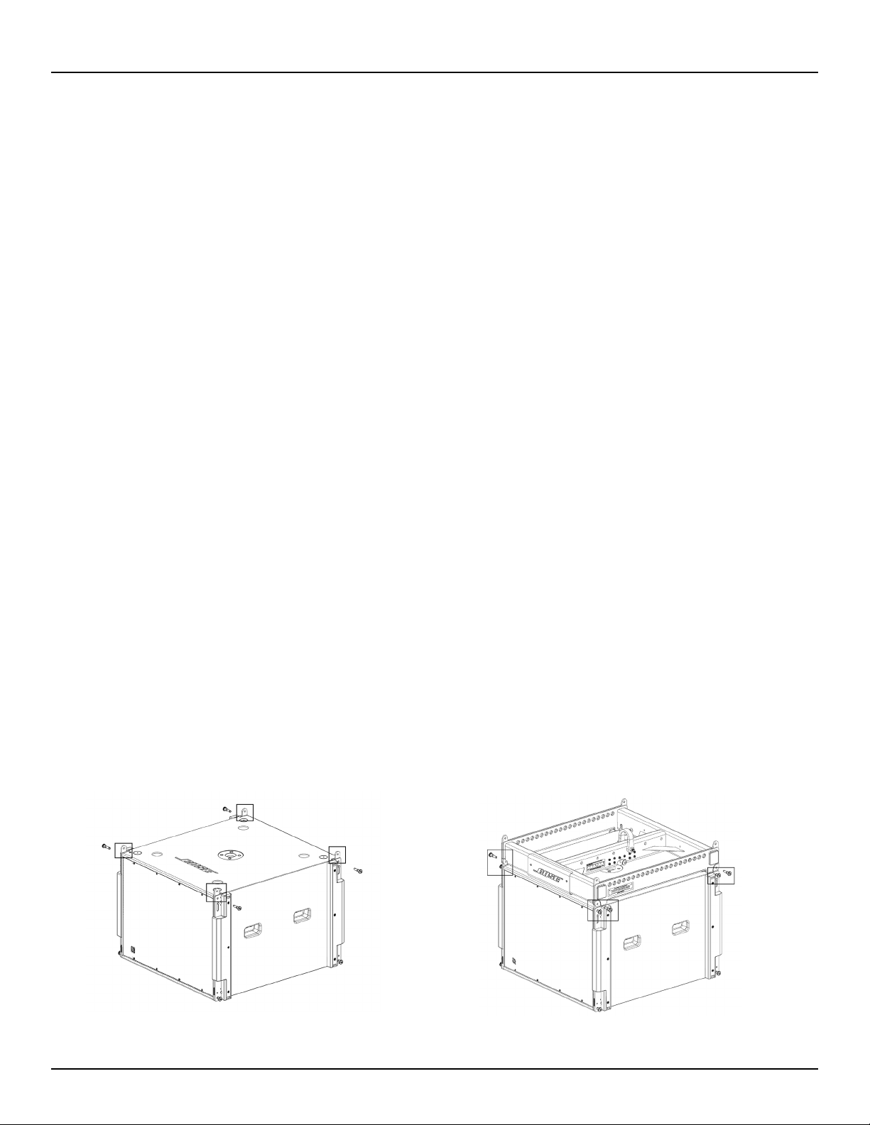
10. Insert two front pins (one on each side), then insert two rear pins (one on each side) to secure subwoofer
to frame. See Fig. 4.
11. Raise array frame to a height slightly greater than that of the next module.
12. With one person per side, place next module directly under suspended array.
13. Lower array onto next module.
14. Align links of second (bottom) module to links of first (top) module.
15. Insert two front pins (one on each side), then insert rear center pin to secure bottom module.
16. Repeat steps to install additional modules in the array. Do not exceed load limits of frame.
17. Connect field wiring, test loudspeaker operation, and then elevate array assembly to final operating
position.
Fig. 3. Raise links on subwoofer
Fig. 4. Insert pins to attach subwoofer to frame
Loading ...
Loading ...
Loading ...