
This thermostat requires 24 Volt AC Power or two (2) properly installed
“AA” Alkaline batteries for proper operation. When connecting 24 Volt
AC Power the batteries may be installed as a backup.
For use only as described in this manual. Any other use
will void warranty.
2020
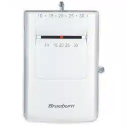
Single Stage Heat / Cool
Conventional and Heat Pump
1
Specifications
2
About Your Thermostat
3
Installation
4
System Testing
5
Setting User Options
6
Setting Your Program Schedule
7
Operating Your Thermostat
8
Additional Operation Features
9
Thermostat Maintenance
®
Warning
Turn off power to the heating or cooling
equipment before installation.
Attention
For installation by experienced service
technicians only.
2220
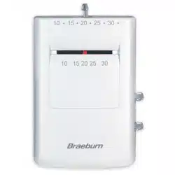
Up to 2 Heat / 2 Cool Conventional
Up to 2 Heat / 1 Cool Heat Pump
Read all instructions before proceeding.
This thermostat is compatible with:
•Singlestageheat/coolconventionalandheatpumpsystems
•Conventionalsystemsupto2heat/2cool(2220only)
•
Singlecompressorheatpumpsystemswithanauxiliaryheatstage(2220only)
•250–750millivoltheatonlysystems
Electrical and control specifications:
•ElectricalRating:24VoltAC
•1ampmaximumloadperterminal
•ACPower:18–30VoltsAC
•DCPower:3.0VoltDC(2“AA”AlkalineBatteriesIncluded)
•ControlRange:45°–90°F(7°–32°C)
•TemperatureAccuracy:+/-1°F(+/-.5°C)
Terminations
•2020–Rc,Rh,O,B,Y1,W1,G,C
•2220–Rc,Rh,O,B,Y1,Y2,E/W1,G,W2,C
1
Specifications
2020W-100-06
Model number is located on back of thermostat
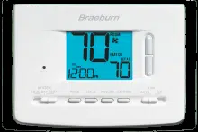
Programmable
Thermostats
Detailed
User Guide
1
6
Setting Your Program Schedule
7
Operating Your Thermostat
8
Additional Operation Features
9
Thermostat Maintenance
For installation by experienced service
technicians only.
2
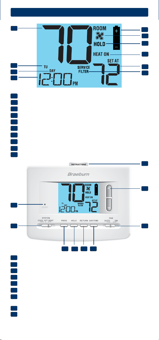
About Your Thermostat
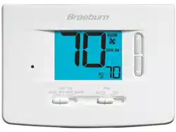
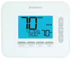
Room Temperature........... Displaysthecurrentroomtemperature
Day of Week......................Displaysthecurrentdayofweek
Program Event Indicator. . Indicatesthecurrentprogramevent
Time of Day....................... Displaysthecurrenttimeofday
Low Battery Indicator......
Indicateswhenbatteriesneedtobereplaced
Fan Indicator.................... Indicateswhenthesystemfanisrunning
Hold Mode Indicator.........DisplaysifinHOLDmode
System Status Indicator...Displaysinformationaboutsystemstatus
Set Temperature...............Displaysthecurrentsetpointtemperature
Service Filter Indicator.....Displaysservice/maintenancereminders
1
2
3
4
5
7
5
6
8
9
6
7
8
10
9
10
1
2
4
3
Reset Button..........
Resetsthermostatbacktofactorydefaults
System Switch.......
Selectssystempreference
PROG Button..........Selectsprogrammingmode
HOLD Button.......... Enters/ExitstheHOLDmode(programbypass)
RETURN Button......Returnstonormalfromprogramorsettingmodes
DAY/TIME Button...Usedtosetthetimeanddayofweek
Quick Reference
Instructions........... Storedinslotattopofthermostat
Arrow Buttons....... Usedtoincreaseordecreasesettings
Fan Switch.............Selectsthesystemfanmode
Battery Compartment.... Locatedinbackofthethermostat
11
12
17
13
14
15 16
18
19
11
12
13
14
15
16
17
18
19
2
Install your new Braeburn thermostat in 5 basic steps:
1 InstalltheSub-Base
2 ProvidePower
3 ConnectYourWires
4 SetInstallerSwitches
5 AttachThermostattoSub-Base
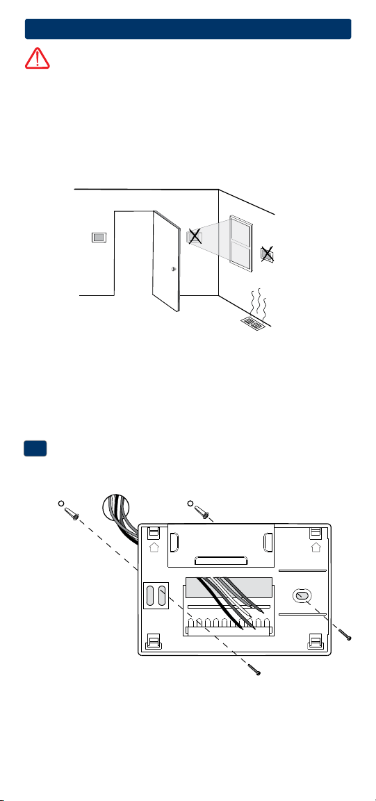
Install the Sub-Base:
•Removethesub-basefromthebodyofthethermostat.
•Mountthesub-baseasshownbelow:
1
NOTE: After sub-base installation, you may insert the quick reference card
into the slot on the top of the base.
3
Installation
Warning
Disconnect power before beginning installation.
Thermostat Location
Installthethermostatapproximately5feet(1.5m)abovetheoorinan
areathathasagoodamountofaircirculationandmaintainsanaverage
roomtemperature.
Avoidinstallationinlocationswherethethermostatcanbeaffectedby
drafts,deadairspots,hotorcoldairducts,sunlight,appliances,concealed
pipes,chimneysandoutsidewalls.
Drill 3/16” pilot holes in
your desired location.
Use supplied anchors for
drywall or plaster.
UP UP
3
Terminal Function Description
Rc Input 24VoltACCoolingTransformer
(DualTransformerSystemsOnly)
Rh Input PowerConnection(24VoltACHeating
TransformerorMillivoltPowerSource)
O Output ReversingValve(CoolActive)
B Output ReversingValve(HeatActive)
Y1 Output CompressorRelay
G Output FanControl
W1 Output ConventionalHeatRelay
C Input 24VoltACTransformerCommon
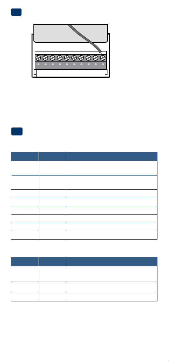
Connect Your Wires
3
Wiring Terminations
Terminal Function Description
W1/E Output (W1)1stStageConventionalHeat
(E)EmergencyHeatRelay
Y2 Output
2ndStageConventionalCoolingCompressor
W2 Output 2ndStageHeat/AuxiliaryHeat
Additional Terminations (2220 only)
Provide Power
•For 24 Volt AC power,youmustconnectthecommonsideofthetrans-
formertotheCterminalonthethermostatsub-base.
•For primary or back-up power,insertthe2supplied“AA”typealkaline
batteriesintothebatterycompartmentlocatedintherearhousingofthe
thermostat.MakesuretopositionthePositive(+)andNegative(-)sides
ofthebatteriescorrectlywiththe+/-symbolsinthebatterycompartment.
24VAC Power
Terminal (C)
2
C

4
1 HEAT / 1 COOL Single or Dual Transformer
Set Installer Switch to CONV
Rh
24VoltACPower(heatingtransformer)[note 2]
Rc
24VoltACPower(coolingtransformer)[note 2]
W1 HeatRelay(appearsasW1/Eon2220)
Y1 CompressorRelay
G FanRelay
C 24VoltACTransformerCommon[note 1, 3]
Typical Wiring Configurations
NOTE: The “Installer Switch” option will be configured in the next step.
Conventional Systems
24VAC Power
Terminal (C)
NOTES - Conventional Systems
[1]Ifbatteriesareinstalledthe24VoltACcommonconnectionisoptional
[2]Removefactoryinstalledjumperfordualtransformersystems
[3]Indualtransformersystems,transformercommonmustcomefrom
coolingtransformer
[4]Ifneededforsystem
Provide disconnect and overload protection as required.
2 HEAT / 2 COOL Single or Dual Transformer (2220 Only)
Set System Type to CONV
Rh
24VoltACPower(heatingtransformer)[note 2]
Rc
24VoltACPower(coolingtransformer)[note 2]
W1 HeatRelayStage1
W2 HeatRelayStage2
Y1 CompressorRelayStage1
Y2 CompressorRelayStage2 [note 4]
G FanRelay
C 24VoltACTransformerCommon[note 1, 3]
Heat Only or Millivolt
Set Installer Switch to CONV
Rh
PowerConnection
W HeatRelay(appearsasW1/Eon2220)
G FanRelay[note 4]
C 24VoltACTransformerCommon[note 1]

Factory Setting
Switch Default Options Comments
5
NOTES - Heat Pump Systems
[1]Ifbatteriesareinstalledthe24VoltACcommonconnectionisoptional.
[2]SelectOforcoolactiveor Bforheatactive.
[3]InstallaeldsuppliedjumperbetweentheW2 and Eterminalsif
thereisnoseparateemergencyheatrelayinstalled.
Provide disconnect and overload protection as required.
CONV/HP CONV
F/C F
HE/HG HG
Set Installer Switches
4
CONV Selectforconventionalsystems
HP Selectforheatpumpsystems
F Selectforfahrenheittemperaturescale
C Selectforcelsiustemperaturescale
HG Selectforgasheat
HE Selectforelectricheat
Typical Wiring Configurations
NOTE: The “Installer Switch” option will be configured in the next step.
Heat Pump Systems
1 HEAT / 1 COOL - No Auxiliary Heat
Set Installer Switch to HP
Rh 24VoltACPower
Rc ConnectedtoRhwithsuppliedJumperWire
O or B
ChangeoverValve [note 2]
Y1 CompressorRelay
G FanRelay
C 24VoltACTransformerCommon [note 1]
2 HEAT / 1 COOL - Including Auxiliary Heat (2220 only)
Set Installer Switch to HP
Rh 24VoltACPower
Rc ConnectedtoRhwithsuppliedJumperWire
O or B
ChangeoverValve[note 2]
Y1
CompressorRelay(1ststageheating/cooling)
W2 AuxiliaryHeatRelay(2ndstageheating)
[note 3]
E EmergencyHeatRelay[note 3]
G FanRelay
C 24VoltACTransformerCommon [note1]
TheInstallerswitchesarelocatedonthebackofthethermostatandmust
beproperlysetforthisthermostattooperateproperly.
6
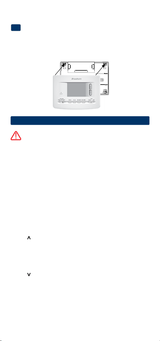
Attach Thermostat to Sub-Base
5
1.Lineupthethermostatbodywiththesub-base.
2.Carefullypushthethermostatbodyagainstthesub-baseuntilitsnaps
intoplace.
3.Insertquickreferencecardintoslotontopofthermostat.
4
System Testing
Warning
Read Before Testing
• Donotshort(orjumper)acrossterminalsonthegasvalveoratthe
heatingorcoolingsystemcontrolboardtotestthethermostatinstalla-
tion.Thiscoulddamagethethermostatandvoidthewarranty.
• DonotselecttheCOOLmodeofoperationiftheoutsidetemperature
isbelow50ºF(10ºC).Thiscouldpossiblydamagethecontrolledcool-
ingsystemandmaycausepersonalinjury.
• Thisthermostatincludesanautomaticcompressorprotectionfeatureto
avoidpotentialdamagetothecompressorfromshortcycling.When
testingthesystem,makesuretotakethisdelayintoaccount.
NOTE: The compressor delay can be bypassed by pressing the reset button
on the front of the thermostat. All user settings will be returned to factory
default.
1 MovetheSYSTEMswitchtoHEATmode.
2 Presstoraisethesettemperatureaminimumof3degreesabove
thecurrentroomtemperature.Thesystemshouldstartwithinafew
seconds.Withagasheatingsystem,thefanmaynotstartrightaway.
3 MovetheSYSTEMswitchtotheOFFmode.Allowtheheatingsystemto
fullyshutdown.
4 MovetheSYSTEMswitchtotheCOOLmode.
5 Presstolowerthesettemperatureaminimumof3degreesbelow
thecurrentroomtemperature.Thesystemshouldstartwithinafew
seconds(unlesscompressorshortcycleprotectionisactive–See
noteabove).
6 MovetheSYSTEMswitchtotheOFFmode.Allowthecoolingsystemto
fullyshutdown.
7 MovetheFANswitchtotheONmode.Thesystemfanshouldstart
withinafewseconds.
8
MovetheFANswitchtotheAUTOmode.Allowthesystemfantoturnoff.
NOTE: Installer switches are located on the back of the thermostat. The
reset button must be pressed after making any changes to these switches.
UP UP

7
User Factory Setting
No. Options Default Options Comments
1
Programming
PRO 7 PRO 7
Selectfor7DayProgrammingMode
Mode PRO 52 Selectfor5-2DayProgrammingMode
PRO NO SelectforNon-ProgrammableMode
2 1ststage
0.5
0.5, 1.0,
Selecta1ststagetemperature
differential
2.0 differentialof.5˚,1˚or2˚F(0.2˚,
0.5˚or1˚C)
3
2ndstage
2.0
1.0, 2.0,
Selecta2ndtemperature
differential
3.0, 4.0
, differentialof1˚,2˚,3˚,4˚,5˚or6˚F
(2220Only)
5.0, 6.0
(.5˚,1˚,1.5˚,2˚,2.5˚or3˚C)
LNG
Selectslong(permanent)holdmode
24HRS
Selects24hr.(temporary)holdmode
5
OFF
Disableslterservicemonitorfeature
30, 60, 90
, Selectsanumberofdaysbefore
120, 180, thethermostatwillashaService
365 Filterreminderinthedisplay.
6 OF REC Disablesadaptive(early)
recoverymode
ON REC Enablesadaptive(early)
recoverymode
Table of User Options
Detailed Explanation of User Options:
Programming Mode
(User Option 1)
Selectstheprogrammingmode(choosefrom7day,5-2Day(weekday/
weekend)programmingornon-programmable.
Temperature Differential
(User Option 2 and 3)
Thedifferentialsettingisthetemperaturecontrolrangethatyourthermostat
willprovide.Thesmallerthesetting,thetighteryourrangeoftemperature
controlandcomfortwillbe.The2ndstagedifferentialisonlyforsystems
withasecondstageofheating(auxiliaryheat).
5
Setting User Options
Advanced User Options
Useroptionsallowyoutocustomizesomeofyourthermostat’sfeatures.
Mostuserswillnotneedtomakeanychangestothesettingsinthissection.
To enter the User Options menu, hold down the RETURN button
for
approximately 3 seconds until the screen changes and displays the
first User Option.
PresstheorbuttontochangethesettingforthedisplayedUserOption.
Afteryouhavemadeyourdesiredsetting,pressRETURNtoadvancetothe
nextUserOption.
Thethermostatwillreturntonormalmodeafteryourlastuseroptionis
madeorafternokeyshavebeenpressedfor15seconds.
Extended
HoldPeriod*
Filter
Service
Monitor
LNG
Adaptive
Recovery
Mode(ARM
TM
)*
OF REC
OFF
4
8
6
Setting Your Program Schedule
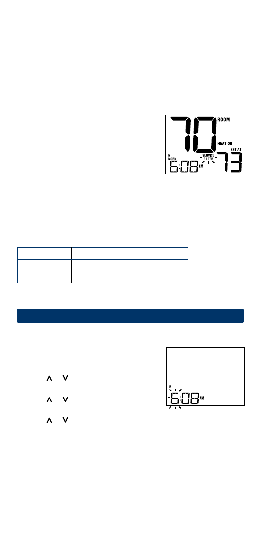
Setting the Time and Day
1.
Innormaloperatingmode,presstheDAY/TIME
button.Thedisplaywillswitchtotheday/time
settingmodeandthehourwillbeashing.
2. Pressortoadjustthehour.
PressDAY/TIME.
3. Pressortoadjusttheminute.Press
DAY/TIME.
4. Pressortoadjustthedayoftheweek.PressRETURNtoexit.
Extended Hold Period*
(User Option 4)
TheExtendedHoldPeriodletsyouselecttheperiodyourthermostatwill
holdthetemperaturewhentheHOLDmodeisactivated(See“Temperature
Adjustment”).WhenLNGisselectedthethermostatwillholdyour
temperatureindenitely.When24HRisselected,thethermostatwillhold
yourtemperaturefor24hoursandthenreturntothecurrentprogramat
thattime.
Service Filter Monitor
(User Option 5)
TheServiceFilterMonitorisauserselectable
servicemonitorthatwilldisplayareminderfor
arequiredairlterreplacementbyashingthe
SERVICEFILTERsegmentinthedisplay.Whenthe
selectedintervalhasbeenreached,andrequired
cleaningorreplacementhasbeenperformed,
touchtheRETURNbuttontoresetthetimerandresettheservicemonitor.
SelectOFForasetnumberofdaysbeforethereminderwillappear.
Adaptive Recovery Mode (early recovery)*
(User Option 6)
AdaptiveRecoveryModeisausersettingthatcontrolswhenthethermostat
willstarttorecoverfromsetback.
Tips Before Setting Your Program Schedule
• Makesureyourcurrenttimeanddayoftheweekaresetcorrectly.
• Whenprogramming,makesuretheAMandPMindicatorsarecorrect.
• YourNIGHTeventcannotexceed11:50p.m.
This thermostat has been configured with one of the following
programming options:
• 7dayprogrammingmodewith4eventsperday(default)
• 5-2(weekday/weekend)programmingmodewith4eventsperday.
• Non-Programmablemode
ARM
TM
Setting Result
OFF Startchangeatprogrammedtime
ON Finishchangeatprogrammedtime
*NotavailableifUserOption1issettonon-programmable
9
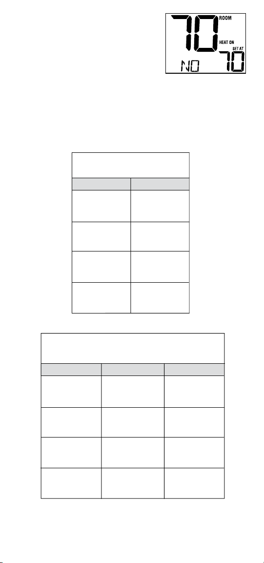
NOTE: If this thermostat was set in the
Installer Settings to be non-programmable, then
you cannot set a user program. If you press the
PROG or HOLD buttons, the word “NO” will
appear in the display, indicating there is no
program present. See section 5, “Setting User
Options” to change this setting.
Energy Saving Programs
Thisthermostatcomespre-programmedwithadefaultenergysaving
program.Thefollowingtablesoutlinethepre-programmedtimesandtem-
peraturesforheatingandcoolingineachofyour4dailyevents.Ifyouwish
tousethesesettingsthennofurtherprogrammingisnecessary:
MORN
DAY
EVE
NIGHT
Time: 6:00 pm
Heat: 70˚ F (21˚ C)
Cool: 78˚ F (26˚ C)
Time: 8:00 am
Heat: 62˚ F (17˚ C)
Cool: 85˚ F (29˚ C)
Time: 6:00 am
Heat: 70˚ F (21˚ C)
Cool: 78˚ F (26˚ C)
Time: 10:00 pm
Heat: 62˚ F (17˚ C)
Cool: 82˚ F (28˚ C)
4 Event
All Days
7 Day Programming
Factory Settings
Weekday Weekend
MORN
DAY
EVE
NIGHT
Time: 6:00 pm
Heat: 70˚ F (21˚ C)
Cool: 78˚ F (26˚ C)
Time: 8:00 am
Heat: 62˚ F (17˚ C)
Cool: 85˚ F (29˚ C)
Time: 6:00 am
Heat: 70˚ F (21˚ C)
Cool: 78˚ F (26˚ C)
Time: 10:00 pm
Heat: 62˚ F (17˚ C)
Cool: 82˚ F (28˚ C)
4 Event
Time: 6:00 pm
Heat: 70˚ F (21˚ C)
Cool: 78˚ F (26˚ C)
Time: 8:00 am
Heat: 62˚ F (17˚ C)
Cool: 85˚ F (29˚ C)
Time: 6:00 am
Heat: 70˚ F (21˚ C)
Cool: 78˚ F (26˚ C)
Time: 10:00 pm
Heat: 62˚ F (17˚ C)
Cool: 82˚ F (28˚ C)
5-2 Day Programming– Weekday/Weekend
Factory Settings
10
Programming a 7 Day Schedule
The7dayprogrammingmodegivesyoutheoptiontoprogramindividual
days(1dayatatime)ortouseSpeedSetandprogramtheentireweek(all
7days)witha4eventprogramschedule.
Setting All 7 Days at Once (SpeedSet
®
)
NOTE: Setting all 7 days at once will copy over any previously programmed
individual days.
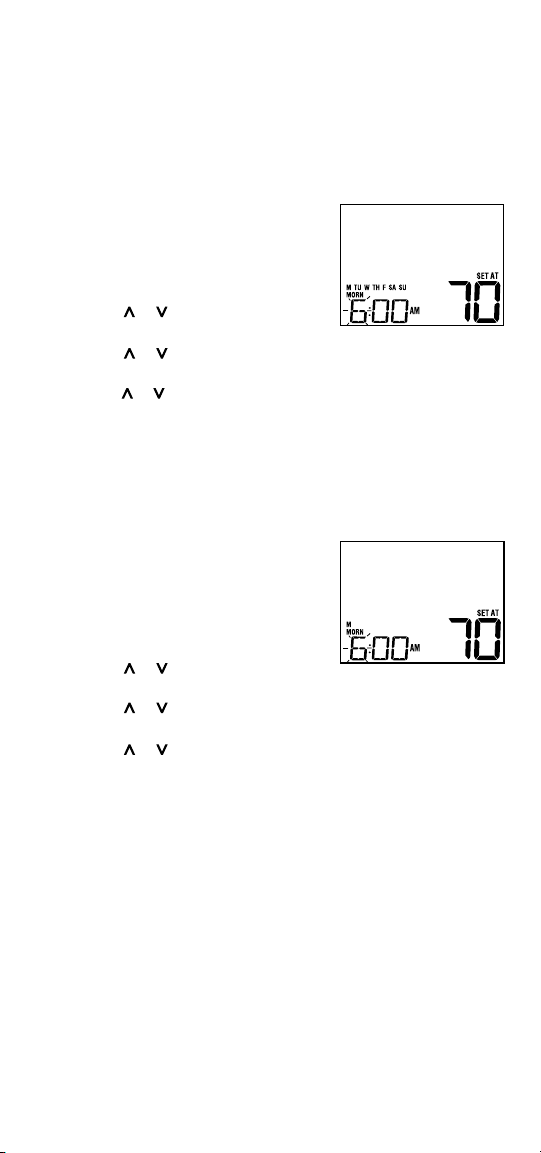
1. HoldthePROGbutton
for3seconds.The
displaywillswitchtoSpeedSetprogramming
mode.All7daysoftheweekwillappearand
thehourwillbeashing.
2. SelectHEATorCOOLwithSYSTEMswitch.
3. Presstheorbuttontoadjustthehour
fortheMORN(morning)event.PressPROG.
4. PresstheorbuttontoadjusttheminutefortheMORNevent.
PressPROG.
5.
Presstheorbuttontoadjustthetemperature
fortheMORNevent.
PressPROG.
6. Repeatsteps3-5fortheDAY,EVEandNIGHTevents.
7.
Ifneeded,repeatsteps2-6toprogramtheoppositemode(HEATorCOOL).
8. PressRETURNtoexit.
Setting Individual Days (7 Day Mode)
1. Pressthe PROGbutton.Thedisplaywill
switchtoprogrammingmode.M(Monday)
willbedisplayedandthehourwillbeashing.
2. SelectHEATorCOOLwithSYSTEMswitch.
3. PressDAY/TIMEtoselectthedayyou
wouldliketoprogram.
4. Presstheorbuttontoadjustthehour
fortheMORN(morning)event.PressPROG.
5. PresstheorbuttontoadjusttheminutefortheMORNevent.
PressPROG.
6. PresstheorbuttontoadjustthetemperaturefortheMORNevent.
PressPROG.
7. Repeatsteps4-6foryourDAY,EVEandNIGHTevents.
8.
Ifneeded,repeatsteps3-6toselectadifferentdaytoprogram.
9. Ifneeded,repeatsteps2-8toprogramtheoppositemode
(HEATorCOOL).
10.PressRETURN toexit.
11
Programming a 5-2 Day Schedule
The5-2dayprogrammingmodeallowsyoutoprogramMonday-Friday
withone4eventscheduleandthenallowsyoutochangeSaturdayand
Sundaywithadifferent4eventschedule.
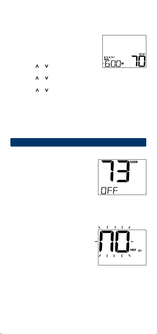
1.
PressthePROGbutton.Thedisplaywillswitch
toprogrammingmode.ThedaysM,TU,W,TH,
andFwillbedisplayedandthehourwillbe
ashing.
2. SelectHEATorCOOLwithSYSTEMswitch.
3. Presstheorbuttontoadjustthehour
fortheMORN(morning)event.Press PROG.
4. PresstheorbuttontoadjusttheminutefortheMORNevent.
PressPROG.
5. PresstheorbuttontoadjustthetemperaturefortheMORNevent.
PressPROG.
6. Repeatsteps3-5foryourDAY,EVEandNIGHTevents.
7. Repeatsteps3-6foryourSaturdayandSunday(S,SU)program.
8. Ifneeded,repeatsteps2-7toprogramtheoppositemode
(HEATorCOOL).
9. PressRETURNtoexit.
7
Operating Your Thermostat
Setting the System Control Mode
TheSystemControlhasseveralmodesof
operationthatcanbeselectedbymovingthe
SYSTEMswitchtotheappropriateposition.
COOL
Onlyyourcoolingsystemwilloperate
OFF Heatingandcoolingsystemsareoff
HEAT Onlyyourheatingsystemwilloperate
Additional Switch Position (Model 2220 Only):
EMER Operatesabackupheatsource(EmergencyHeat)forheatpump
systemsonly
NOTE: If your model 2220 was set for
a
conventional system (CONV) then you will not
have the EMER (emergency heat) option and
“NO EMER SET” will flash in the display if
EMER is selected with the system switch.

Status Indicators
Statusindicatorsappearinthedisplaytoletyouknowifyoursystemis
heating,coolingoroff.
HEAT ON Indicatesthatyourheatingsystem
isrunning.
COOL ON Indicatesthatyourcoolingsystem
isrunning.
SERVICE Indicatesthatauserservice
reminderwasselected(see“Service
FilterMonitor,page8).
Additional status indicators (Model 2220 Only):
AUX Indicatesthattheauxiliarystageofheatingisrunning
(multi-stagesystemsonly).
EMER Indicatesthattheemergencyheatingsystemisrunning(heat
pumpsystemsonly).
Program Event Indicators
ProgramEventIndicatorsappearinthedisplaytoletyouknowwhatpart
ofyourcurrentprogramisactive.The4differentprogrameventindicators
areMORN,DAY,EVEandNIGHT.
Whentheprogrameventindicatorisashing,yourprogramhasbeen
temporarilybypassedandwillresumeatthenextscheduledevent.
Note: You will not see a program event indicator while in HOLD Mode.
Resetting the Thermostat
Thisthermostatprovidesyouwitharesetbuttonthatwilleraseallofyour
usersettingsandprogramming.
Toresetthethermostat,useasmallobjectsuchasatoothpickorpaper-
clipandgentlypressthebuttonlocatedinsidethesmallholeonthefrontof
thethermostathousinglabeled“reset”.
Setting the Fan Control Mode
TheFanControlhas2modesofoperation–AUTOandON.Themodecan
beselectedbymovingtheFANswitchtotheappropriateposition.
AUTO Thesystemfanwillrunonlywhenyour
heatingorcoolingsystemisrunning
ON Thesystemfanstayson
Temperature Adjustment
Temporary Adjustment–Presstheorbuttontoadjustthecurrent
setpointtemperature.
Extended Adjustment–PresstheHOLDbuttonsothatHOLDappearsin
thedisplayscreen.Pressortoadjustthecurrentsettemperature
(See“ExtendedHoldPeriod”,page8).
12
8
Additional Operation Features
Compressor Protection
Thisthermostatincludesanautomaticcompressorprotectiondelaytohelp
avoidpotentialdamagetoyoursystemfromshortcycling.Thisfeature
activatesashortdelayafterturningoffthesystemcompressor.
9
Thermostat Maintenance
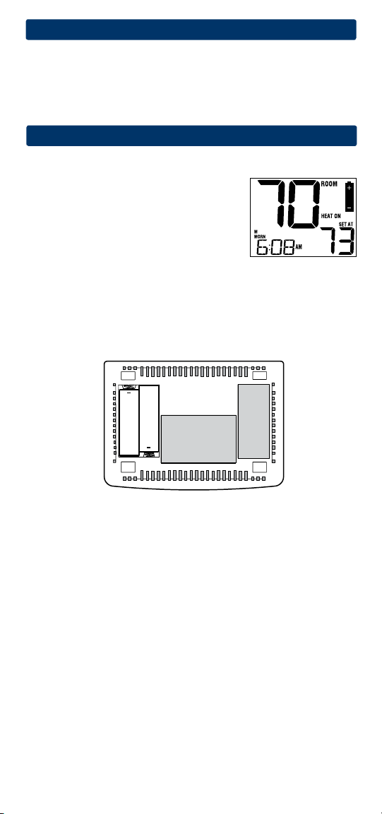
Changing the Batteries
Dependingonyourparticularinstallation,this
thermostatmaybeequippedwithtwo(2)“AA”
typealkalinebatteries.
If batteries are installed and they become low,
a low battery indicator will appear in the display.
You
shouldchangeyourbatteriesimmediately
whenyouseethelowbatterysignalbyfollowing
theseinstructions.
1.Removethermostatbodybygentlypullingitfrombase.
2.Removeoldbatteriesandreplacewithnewbatteries.
3.Makesuretocorrectlypositionthe(+)and(-)symbols.
4.Gentlypushthermostatbodybackontobase.
NOTE: We recommend replacing the thermostat batteries annually or if the
thermostat will be unattended for an extended period of time.
Thermostat Cleaning
Neversprayanyliquiddirectlyonthethermostat.Usingasoftdampcloth
wipetheouterbodyofthethermostat.Neveruseanyabrasivecleansersto
cleanyourthermostat.
+
+

Store this manual for future reference
.
Limited Warranty
Wheninstalledbyaprofessionalcontractor,thisproductisbackedbya5year
limitedwarranty.Limitationsapply.Forlimitations,termsandconditions,you
mayobtainafullcopyofthiswarranty:
·Visitusonline:www.braeburnonline.com/warranty
·Phoneus:866.268.5599
·Writeus:BraeburnSystemsLLC
2215CornellAvenue
Montgomery,IL60538
5
YEAR
WARRANT Y
LIMITED
BraeburnSystemsLLC
2215CornellAvenue•Montgomery,IL60538
TechnicalAssistance:www.braeburnonline.com
Callustoll-free:866-268-5599(U.S.)
630-844-1968(OutsidetheU.S.)
©2014BraeburnSystemsLLC•AllRightsReserved•MadeinChina.
2020W-100-06