Loading ...
Loading ...
Loading ...
Installing the water heater.
12
!
WARNING:
Never use an open
flame to test for gas
leaks, as bodily
injury, property
damage or death
could result.
Leak Testing
The water heater and its gas connections must
be leak tested at normal operating pressures
before it is placed in operation.
Turn on the manual gas shut-off valve
near the water heater.
Use a soapy water solution to test for
leaks at all connections and fittings.
Bubbles indicate a gas leak that must be
corrected.
The factory connections to the gas control
(thermostat) should also be leak tested after the
water heater is placed in operation.
Pressure Testing the Gas Supply System
The water heater and its manual gas shut-
off valve must be disconnected from the gas
supply piping system during any high pressure
testing of that system at pressures in excess of
1/2 psi (14” w.c.).
The water heater must be isolated from the gas
piping system by closing the manual gas shut-
off valve during any pressure testing of the gas
supply piping at pressures equal to or less than
1/2 psi (14” w.c).
High Altitude
Ratings of gas appliances are based
on sea level operation and need not be
changed for installations at elevations up to
7,700 feet.
For installations above 7,700 feet, Please
contact your local distributor or place of
purchase for a high altitude model.
WARNING: Failure to install a water heater
suitable for the altitude at the location it is
intended to serve, can result in improper
operation of the appliance resulting in property
damage and/or, producing carbon monoxide
gas, which could result in personal injury, or
death.
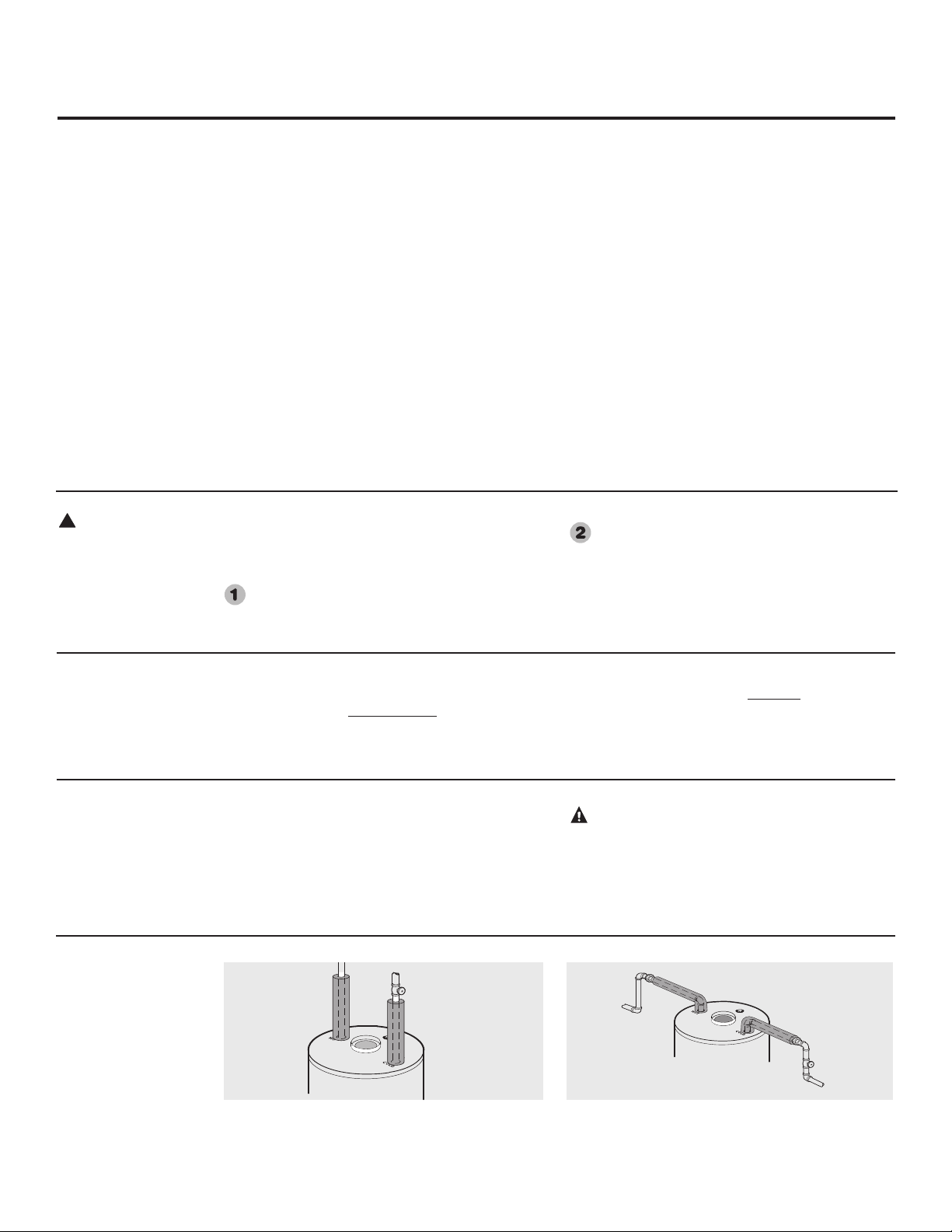
For increased energy efficiency, some water
heaters have been supplied with two 24”
sections of pipe insulation.
Please install the insulation, according to
the illustrations above, that best meets your
requirements.
Typical vertical piping arrangement
Typical horizontal piping arrangement
Hot and Cold Pipe Insulation Installation
Gas Supply
Check the markings on the water heater’s rating plate to
be certain the type of gas being furnished corresponds to
that for which the water heater is built. The water heater
can be converted from natural gas to LP or vice versa.
See the Conversion Instructions section of this manual.
The branch gas supply line to the water heater should be
clean 1/2” black steel pipe or other approved gas piping
material.
A ground joint union or ANSI design certified semi-rigid
or flexible gas appliance connector should be installed
in the gas line close to the water heater. The HUD code
should be followed for installation and location of a
manual shutoff valve. If lever type gas shut-offs are used,
they shall be T-Handle type.
Compound used on the threaded joints of the gas piping
must be of the type resistant to the action of LP gas. Use
compound sparingly on male threads only.
Where a sediment trap is not incorporated as part of the
appliance, a sediment trap shall be installed downstream
of the equipment shutoff valve as close to the inlet of
the appliance as practical at the time of the appliance
installation. The sediment trap shall be either a tee fitting
with a capped nipple in the bottom outlet or other device
recognized as an effective sediment trap. Do not use
excessive force (over 31.5 ft lbs.) in tightening the pipe
joint at the thermostat inlet, particularly if teflon pipe
compound is used, as the valve body may be damaged.
The inlet gas pressure to the water heater must not
exceed 14” w.c. for natural or LP gas. For purposes of
input adjustment, the minimum inlet gas pressure (with
main burner on) is shown on the water heater rating plate.
If high or low gas pressures are present, contact your gas
supplier for correction.
If flexible connectors are used, the maximum length shall
not exceed 36” (91 cm).
Loading ...
Loading ...
Loading ...